EP1571364A1 - Disk brake for a vehicle - Google Patents
Disk brake for a vehicle Download PDFInfo
- Publication number
- EP1571364A1 EP1571364A1 EP05250599A EP05250599A EP1571364A1 EP 1571364 A1 EP1571364 A1 EP 1571364A1 EP 05250599 A EP05250599 A EP 05250599A EP 05250599 A EP05250599 A EP 05250599A EP 1571364 A1 EP1571364 A1 EP 1571364A1
- Authority
- EP
- European Patent Office
- Prior art keywords
- shim
- pressuring
- brake
- disk rotor
- respect
- Prior art date
- Legal status (The legal status is an assumption and is not a legal conclusion. Google has not performed a legal analysis and makes no representation as to the accuracy of the status listed.)
- Granted
Links
- 239000002184 metal Substances 0.000 description 39
- 229910052751 metal Inorganic materials 0.000 description 39
- 150000002739 metals Chemical class 0.000 description 9
- 230000000052 comparative effect Effects 0.000 description 3
- 239000012530 fluid Substances 0.000 description 3
- 239000002783 friction material Substances 0.000 description 2
- 230000036544 posture Effects 0.000 description 2
- 230000012447 hatching Effects 0.000 description 1
- 238000000034 method Methods 0.000 description 1
- 238000012986 modification Methods 0.000 description 1
- 230000004048 modification Effects 0.000 description 1
- 230000002093 peripheral effect Effects 0.000 description 1
- 230000000452 restraining effect Effects 0.000 description 1
- 230000000717 retained effect Effects 0.000 description 1
- 230000006641 stabilisation Effects 0.000 description 1
- 238000011105 stabilization Methods 0.000 description 1
Images


Classifications
-
- F—MECHANICAL ENGINEERING; LIGHTING; HEATING; WEAPONS; BLASTING
- F16—ENGINEERING ELEMENTS AND UNITS; GENERAL MEASURES FOR PRODUCING AND MAINTAINING EFFECTIVE FUNCTIONING OF MACHINES OR INSTALLATIONS; THERMAL INSULATION IN GENERAL
- F16D—COUPLINGS FOR TRANSMITTING ROTATION; CLUTCHES; BRAKES
- F16D65/00—Parts or details
- F16D65/02—Braking members; Mounting thereof
- F16D65/04—Bands, shoes or pads; Pivots or supporting members therefor
- F16D65/092—Bands, shoes or pads; Pivots or supporting members therefor for axially-engaging brakes, e.g. disc brakes
- F16D65/095—Pivots or supporting members therefor
- F16D65/097—Resilient means interposed between pads and supporting members or other brake parts
- F16D65/0971—Resilient means interposed between pads and supporting members or other brake parts transmitting brake actuation force, e.g. elements interposed between brake piston and pad
-
- F—MECHANICAL ENGINEERING; LIGHTING; HEATING; WEAPONS; BLASTING
- F16—ENGINEERING ELEMENTS AND UNITS; GENERAL MEASURES FOR PRODUCING AND MAINTAINING EFFECTIVE FUNCTIONING OF MACHINES OR INSTALLATIONS; THERMAL INSULATION IN GENERAL
- F16D—COUPLINGS FOR TRANSMITTING ROTATION; CLUTCHES; BRAKES
- F16D55/00—Brakes with substantially-radial braking surfaces pressed together in axial direction, e.g. disc brakes
- F16D55/02—Brakes with substantially-radial braking surfaces pressed together in axial direction, e.g. disc brakes with axially-movable discs or pads pressed against axially-located rotating members
- F16D55/22—Brakes with substantially-radial braking surfaces pressed together in axial direction, e.g. disc brakes with axially-movable discs or pads pressed against axially-located rotating members by clamping an axially-located rotating disc between movable braking members, e.g. movable brake discs or brake pads
- F16D55/224—Brakes with substantially-radial braking surfaces pressed together in axial direction, e.g. disc brakes with axially-movable discs or pads pressed against axially-located rotating members by clamping an axially-located rotating disc between movable braking members, e.g. movable brake discs or brake pads with a common actuating member for the braking members
-
- F—MECHANICAL ENGINEERING; LIGHTING; HEATING; WEAPONS; BLASTING
- F16—ENGINEERING ELEMENTS AND UNITS; GENERAL MEASURES FOR PRODUCING AND MAINTAINING EFFECTIVE FUNCTIONING OF MACHINES OR INSTALLATIONS; THERMAL INSULATION IN GENERAL
- F16D—COUPLINGS FOR TRANSMITTING ROTATION; CLUTCHES; BRAKES
- F16D65/00—Parts or details
- F16D65/0006—Noise or vibration control
Definitions
- the present invention relates to a disk brake that has a pressuring element provided for pressing a brake pad against a disk rotor via a shim so as to generate a braking force.
- a disk brake In the state of art, a disk brake is well-known that has a shim (shim plate) for anti-brake shudder provided between a back metal of a brake pad and a pressuring element (a piston or a pawl portion of a cylinder) for pressing the brake pad against a disk rotor.
- JP2003-329067 A discloses this type of a disk brake, in which on the shim are formed a plural of projections (dimples) so as to establish contact between the pressuring element and the projections of the shim under a low pressuring force at a low braking force.
- JP4-138137 A discloses a technique for reducing brake shudder by providing a shim on a back metal such that the shim can move with respect to the back metal and thus permitting movement of the shim with respect to the back metal during a braking operation.
- stoppers for limiting the range of the movement of the shim in order to prevent unlimited movement of the shim with respect to the back metal.
- stoppers for limiting the range of the movement of the shim in order to prevent unlimited movement of the shim with respect to the back metal.
- wall portions for limiting the movement of the hooks beyond a predetermined amount.
- a disk brake has a pressuring element provided for pressing a brake pad against a disk rotor via a shim during a braking operation, comprising: a stopper portion that acts on the shim for stopping a movement of the shim with respect to the brake pad, wherein a point of action of the stopper portion on the shim is provided at the downstream side in a rotating direction of the disk rotor with respect to a point of action of the pressuring element on the shim.
- each stopper portion being provided according to a different direction of the disk rotor, and points of action of the stopper portions on the shim are provided symmetrically in a rotating direction of the disk rotor with respect to a point of action of the pressuring element on the shim.
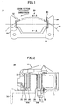
- Fig. 1 is a plan view of a disk brake 10 according to an embodiment of the present invention
- Fig. 2 is a cross-sectional view A-A in Fig. 1.
- a cylinder body (caliper) is not shown for illustrating the inside of disk brake 10.
- the disk brake 10 has a mounting bracket 20 (hereafter referred to as simply “mounting 20") that is mounted to a vehicle body.
- mounting 20 On the mounting 20 is supported brake pads 50 (an inner pad 50a and an outer pad 50b) via pad clips 40.
- the inner pad 50a and the outer pad 50b are arranged such that they sandwich a disk rotor 14, which rotates together with a wheel, from inboard and outboard sides, respectively, of the vehicle.
- the brake pads 50 are provided with friction materials 56 that are pressed on sliding surfaces of the disk rotor 14, and on the back sides of the friction materials 56 (the back side is determined assuming that the side opposed to the disk rotor 14 is the front side) are provided back metals (back plates) 54, as shown in Fig. 2.
- the back metals 54 of the brake pads 50 are provided with convex portions 52 on both ends in a rotating direction of the disk rotor 14, as shown in Fig. 1.
- the convex portions 52 of the back metals 54 are supported via pad clips 40 in concave portions (channels) 22 formed in the mounting 20.
- the pad clips 40 may support the convex portions 52 of the back metals 54 such that the convex portions 52 are floated in the concave portions 22 of the mounting 20.
- the convex portions 52 of the back metals 54 are supported such that they can move in an inner radial direction of the disk rotor 14.
- the disk brake 10 has a cylinder body 30 (hereafter referred to as simply "cylinder 30"), as shown in Fig. 2.
- the cylinder 30 is attached to the mounting 20 via a slide pin or the like (not shown).
- the cylinder 30 is supported on the mounting 20 via a slide pin with bushings that crosses the disk rotor 14 in the direction between inboard and outboard sides of the vehicle.
- the cylinder 30 has a piston 34 and a pawl portion 32 arranged such that they sandwich the inner pad 50a and the outer pad 50b from inboard and outboard sides, respectively, of the vehicle.
- the cylinder 30 is connected in fluid communication with a brake master cylinder (not shown) via pressured fluid channels.
- the disk brake 10 may be arranged in any angular position in a circumferential direction of the wheel.
- shims 70 On the back sides of the back metals 54 of the brake pads 50 are provided shims 70 described later, as shown in Fig. 2.
- the piston 34 or the pawl portion 32 is abutted and pressed on the back side of shim 70.
- the inner pad 50a and the outer pad 50b are subjected to pressuring forces from the piston 34 or the pawl portion 32 toward the disk rotor 14 via the respective shims 70.
- Fig. 3 is a plan view of a shim 70 on a brake pad according to the embodiment.
- Fig. 4 is a cross-sectional view B-B in Fig. 3. It is noted that explanation is made below for only the arrangement on the side related to the inner pad 50a, since there is substantially no difference with respect to the arrangement on the side related to the outer pad 50b.
- the shim 70 is arranged on the back surface of the back metal 54 of the brake pads 50 such that the shim 70 covers substantially all the area of the back metal 54 except the peripheral area thereof, as shown in Fig. 3.
- hook (nail) portions 72 On the perimeter of the shim 70 are formed hook (nail) portions 72.
- the hook portions 72 are supported such that they can move with respect to the back metal 54 in a plane that is parallel with a basic plane of the back metal 54, in particular, in the direction that substantially corresponds to the rotating direction of the disk rotor 14 (a lateral direction in Fig. 3).
- the hook portions 72 of the shim 70 are hooked to concave portions (channel portions) 55 that are formed on the perimeter of the back metal 54, and movably retained in the concave portions 55, as shown in Fig. 4.
- the hook portions 72 are located on the outside of a contact portion 54b that contacts the piston 34 (i.e. a pressuring portion 54b of the piston 34), and two hook portions 72 are provided symmetrically in the rotating direction of the disk rotor 14 with respect the pressuring portion 54b.
- the hook portions 72 are not necessarily formed symmetrically with respect the pressuring portion 54b, and more than three hook portions 72 may be provided.
- the hook portions 72 are located on the outside of a contact portion with the pawl portion 32 (i.e. a pressuring portion of the pawl portion 32), and two hook portions 72 are provided symmetrically in the rotating direction of the disk rotor 14 with respect the pressuring portion of the pawl portion 32. It is noted that, in the following description, "a pressuring portion of a pawl portion 32" in the arrangement on the side related to the outer pad 50b corresponds to "a pressuring portion 54b of a piston 34", as previously described.
- the condition is established in which the back metals 54 of the brake pads 50 are pressed on the disk rotor 14 and the shim 70 is pressed on the piston 34.
- the back metals 54 of the brake pads 50 can move with respect to the piston 34 as a result of the movement with respect to the shim 70.
- a point of action on the shim 70 of the rotation force of the disk rotor 14 applied via the hook portion 72 is provided at a downstream side (outlet side of the disk rotor 14) in a rotating direction of the disk rotor 14 with respect to a point of action on the shim 70 of the pressuring force applied by the pressuring portion 54b of the piston 34.
- the locations of the hook portions 72 within the concave portions 55 of the back metal 54 are biased to the side of the pressuring portion 54b of the piston 34, that is to say, to the center of the back metal 54.
- distances "a" between the hook portions 72 and the inner side walls (center side walls) of the concave portions 55 are set smaller than distances "b" between the hook portions 72 and the outer side walls of the concave portions 55.
- the pressuring force from the piston 34 will act on the shim 70 in a heterogeneous pattern (the same goes for the case of rotating in the clockwise direction).
- the piston 34 presses the shim 70 in the lifted state, and the postures of the brake pads become unstable, which enhances brake shudder.
- gaps ⁇ between the side edges of the back metal 54 and the side edges of the shim 70 are set such that the side portions of the shim 70 cannot extend off the back metal 54 by considering the movable range of the shim 70 with respect to the back metal 54, as shown in Fig. 3.
- the gap ⁇ is set sufficiently bigger than the movable amount "a" of the hook portion 72 in the concave portion 55 (the distance "a” between the hook portions 72 and the center side wall of the concave portion 55).
- the present invention is not limited to this structure.
- the present invention covers any structures as long as the stopping force is applied to the hook portion 72 of the shim 70 at the outside of the pressuring portion 54b of the piston 34 and in an outward direction with respect to the pressuring portion 54b.
- the structure in which the outer side walls of the concave portions 55 are omitted is also possible.
- the stoppers between the shim 70 and the back metal 54 are implemented by the hook portions 72 of the shim 70 and the concave portions 55 of the back metal 54
- the present invention is not limited to this structure.
- a structure in which projected portions formed on the shim 70 are inserted or fitted in through holes or concave portions formed in the back metal 54, and a structure in which projected portions formed on the back metal 54 are inserted or fitted in through holes or concave portions formed in the shim 70 are also possible.
- the separate shim (referred to as "an inner shim") may be attached to the back metal 54 such that it cannot move substantially, and thus the inner shim may have a function of easing the slide (movement) of the outer shim 70.
- the same structure as the aforementioned back metal 54 may be provide to the inner shim.
- stopper portions for stopping the movement of the shim 70 may be set between the inner shim and the outer shim 70, wherein the stopper portions may apply the stopping force to the outer shim 70 at the outside of the pressuring portion 54b of the piston 34 and in an outward direction (in the rotating direction of the disk rotor 14) with respect to the pressuring portion 54b.
- the stopper portions between the back metal 54 and the shim 70 are set at the upper side of the shim 70, that is to say, at the outer side in the radius direction, however, it is also possible to set the stopper portions at the lower side of the shim 70.
- this arrangement in a case where the width of the pressuring portion 54b by the pawl portion 32 is smaller in the lower side of the shim 70 than that in the upper side of the shim 70, it becomes easier to set the stopper portions on the shim 70 at the outside of the pressuring portion 54b of the pawl portion 32 of the cylinder 30.
Landscapes
- Engineering & Computer Science (AREA)
- General Engineering & Computer Science (AREA)
- Mechanical Engineering (AREA)
- Braking Arrangements (AREA)
Abstract
Description
- The present invention relates to a disk brake that has a pressuring element provided for pressing a brake pad against a disk rotor via a shim so as to generate a braking force.
- In the state of art, a disk brake is well-known that has a shim (shim plate) for anti-brake shudder provided between a back metal of a brake pad and a pressuring element (a piston or a pawl portion of a cylinder) for pressing the brake pad against a disk rotor. JP2003-329067 A discloses this type of a disk brake, in which on the shim are formed a plural of projections (dimples) so as to establish contact between the pressuring element and the projections of the shim under a low pressuring force at a low braking force. JP4-138137 A discloses a technique for reducing brake shudder by providing a shim on a back metal such that the shim can move with respect to the back metal and thus permitting movement of the shim with respect to the back metal during a braking operation.
- In general, on such type of a disk brake are provided stoppers for limiting the range of the movement of the shim in order to prevent unlimited movement of the shim with respect to the back metal. For example, in a structure in which the shim has hooks hooked at the perimeter of the back metal, on the perimeter of the back metal are formed wall portions for limiting the movement of the hooks beyond a predetermined amount. With such a structure, forces are applied to the shim by the pressuring element and the wall portion during a braking operation; however, depending on a positional relationship between points of action of these forces, non-uniformity in the distribution of pressuring forces on the shim applied by the pressuring element may occur, causing a bottleneck in reducing brake shudder.
- It is an object of the present invention to provide a disk brake in which brake shudder is efficiently reduced.
- In order to achieve the above-mentioned object, according to one aspect of the present invention a disk brake is provided that has a pressuring element provided for pressing a brake pad against a disk rotor via a shim during a braking operation, comprising: a stopper portion that acts on the shim for stopping a movement of the shim with respect to the brake pad, wherein a point of action of the stopper portion on the shim is provided at the downstream side in a rotating direction of the disk rotor with respect to a point of action of the pressuring element on the shim.
- In this aspect of the invention, it is advantageous if two stopper portions are provided, each stopper portion being provided according to a different direction of the disk rotor, and points of action of the stopper portions on the shim are provided symmetrically in a rotating direction of the disk rotor with respect to a point of action of the pressuring element on the shim.
- Other objects, features and advantages of the present invention will become more apparent from the following detailed description when read in conjunction with the accompanying drawings.
-
- Fig. 1 is a plan view of a disk brake according to an embodiment of the present invention.
- Fig. 2 is a cross-sectional view A-A in Fig. 1.
- Fig. 3 is a plan view of a
shim 70 on a brake pad according to the embodiment. - Fig. 4 is a cross-sectional view B-B in Fig. 3.
- Fig. 5A is an illustration of a status of the
shim 70 in its moved position according to the embodiment of the present invention and Fig. 5B is an illustration of a status of theshim 70 in its moved position according to the comparative example. - Fig. 6A is an illustration of a status of the
shim 70 under the application of a force according to the embodiment of the present invention and Fig. 6B is an illustration of a status of theshim 70 under the application of a force according to the comparative example. -
- Hereafter, the preferred embodiments according to the present invention are explained with reference to the drawings.
- Fig. 1 is a plan view of a
disk brake 10 according to an embodiment of the present invention, and Fig. 2 is a cross-sectional view A-A in Fig. 1. In Fig. 2, a cylinder body (caliper) is not shown for illustrating the inside ofdisk brake 10. - The
disk brake 10 according to this embodiment has a mounting bracket 20 (hereafter referred to as simply "mounting 20") that is mounted to a vehicle body. On themounting 20 is supported brake pads 50 (aninner pad 50a and anouter pad 50b) viapad clips 40. Theinner pad 50a and theouter pad 50b are arranged such that they sandwich adisk rotor 14, which rotates together with a wheel, from inboard and outboard sides, respectively, of the vehicle. - The
brake pads 50 are provided withfriction materials 56 that are pressed on sliding surfaces of thedisk rotor 14, and on the back sides of the friction materials 56 (the back side is determined assuming that the side opposed to thedisk rotor 14 is the front side) are provided back metals (back plates) 54, as shown in Fig. 2. Theback metals 54 of thebrake pads 50 are provided withconvex portions 52 on both ends in a rotating direction of thedisk rotor 14, as shown in Fig. 1. Theconvex portions 52 of theback metals 54 are supported viapad clips 40 in concave portions (channels) 22 formed in themounting 20. It is noted that thepad clips 40 may support theconvex portions 52 of theback metals 54 such that theconvex portions 52 are floated in theconcave portions 22 of themounting 20. In the embodiment illustrated in Fig .1, theconvex portions 52 of theback metals 54 are supported such that they can move in an inner radial direction of thedisk rotor 14. - The
disk brake 10 has a cylinder body 30 (hereafter referred to as simply "cylinder 30"), as shown in Fig. 2. Thecylinder 30 is attached to themounting 20 via a slide pin or the like (not shown). Specifically, thecylinder 30 is supported on themounting 20 via a slide pin with bushings that crosses thedisk rotor 14 in the direction between inboard and outboard sides of the vehicle. Thecylinder 30 has apiston 34 and apawl portion 32 arranged such that they sandwich theinner pad 50a and theouter pad 50b from inboard and outboard sides, respectively, of the vehicle. Typically, thecylinder 30 is connected in fluid communication with a brake master cylinder (not shown) via pressured fluid channels. When the high pressure fluid is supplied to thecylinder 30, thepiston 34 moves toward thepawl portion 32. In this way, theinner pad 50a and theouter pad 50b are pressed toward each other by thepiston 34 and thepawl portion 32 so that theinner pad 50a and theouter pad 50b pinch both sliding surfaces of thedisk rotor 14, generating a braking force. It is noted that thedisk brake 10 may be arranged in any angular position in a circumferential direction of the wheel. - On the back sides of the
back metals 54 of thebrake pads 50 are providedshims 70 described later, as shown in Fig. 2. Thepiston 34 or thepawl portion 32 is abutted and pressed on the back side ofshim 70. Thus, theinner pad 50a and theouter pad 50b are subjected to pressuring forces from thepiston 34 or thepawl portion 32 toward thedisk rotor 14 via therespective shims 70. - Fig. 3 is a plan view of a
shim 70 on a brake pad according to the embodiment. Fig. 4 is a cross-sectional view B-B in Fig. 3. It is noted that explanation is made below for only the arrangement on the side related to theinner pad 50a, since there is substantially no difference with respect to the arrangement on the side related to theouter pad 50b. - The
shim 70 is arranged on the back surface of theback metal 54 of thebrake pads 50 such that theshim 70 covers substantially all the area of theback metal 54 except the peripheral area thereof, as shown in Fig. 3. On the perimeter of theshim 70 are formed hook (nail)portions 72. Thehook portions 72 are supported such that they can move with respect to theback metal 54 in a plane that is parallel with a basic plane of theback metal 54, in particular, in the direction that substantially corresponds to the rotating direction of the disk rotor 14 (a lateral direction in Fig. 3). Specifically, thehook portions 72 of theshim 70 are hooked to concave portions (channel portions) 55 that are formed on the perimeter of theback metal 54, and movably retained in theconcave portions 55, as shown in Fig. 4. In the embodiment illustrated in Fig. 3, thehook portions 72 are located on the outside of acontact portion 54b that contacts the piston 34 (i.e. a pressuringportion 54b of the piston 34), and twohook portions 72 are provided symmetrically in the rotating direction of thedisk rotor 14 with respect the pressuringportion 54b. However, thehook portions 72 are not necessarily formed symmetrically with respect the pressuringportion 54b, and more than threehook portions 72 may be provided. - Similarly, the
hook portions 72 are located on the outside of a contact portion with the pawl portion 32 (i.e. a pressuring portion of the pawl portion 32), and twohook portions 72 are provided symmetrically in the rotating direction of thedisk rotor 14 with respect the pressuring portion of thepawl portion 32. It is noted that, in the following description, "a pressuring portion of apawl portion 32" in the arrangement on the side related to theouter pad 50b corresponds to "a pressuringportion 54b of apiston 34", as previously described. - In this embodiment, during the braking operation, the condition is established in which the
back metals 54 of thebrake pads 50 are pressed on thedisk rotor 14 and theshim 70 is pressed on thepiston 34. Thus, theback metals 54 of thebrake pads 50 can move with respect to thepiston 34 as a result of the movement with respect to theshim 70. With such an arrangement, in the conditions wherein themounting 20 or thecylinder 30 is subjected to deformation, as in the condition during a braking operation with high pressuring force, theback metals 54 of thebrake pads 50 can move with respect to theshim 70 and thus follow the deformation of themounting 20. This leads to improved stabilization in a posture of thebrake pads 50 even in such conditions. In this way, brake shudder that tends to occur during the braking operation is efficiently reduced. - However, as the
shim 70 moves with respect to theback metal 54 as mentioned above, theshim 70 is finally stopped when thehook portion 72 is abutted against a side wall of theconcave portion 55, restraining the movement ofshim 70 with respect to theback metal 54. When a further load urges theshim 70 in this restraint condition of the movement to move further, forces from the pressuringportion 54b of thepiston 34 and from thehook portion 72 that has been stuck by the side wall of theconcave portion 55 act on theshim 70. At this time, depending on a positional relationship between points of action of these forces, an undesired deformation, such as a lifting deformation, may occur in some cases. In such cases, non-uniformity in a distribution of the pressuring force applied by the pressuringportion 54b of thepiston 34 on theshim 70 occurs, causing brake shudder. - Regarding this problem, according to the present invention, a point of action on the
shim 70 of the rotation force of thedisk rotor 14 applied via thehook portion 72 is provided at a downstream side (outlet side of the disk rotor 14) in a rotating direction of thedisk rotor 14 with respect to a point of action on theshim 70 of the pressuring force applied by the pressuringportion 54b of thepiston 34. With this arrangement, since the rotation force of thedisk rotor 14 applied to theshim 70 via thehook portion 72 acts in a tensile direction in a plane with a fulcrum at the pressuringportion 54b of thepiston 34, undesired deformations such as a lifting deformation don't occur around the pressuringportion 54b of thepiston 34. Therefore, with this arrangement, a distribution of the pressuring force (a pressure pattern on the shim 70) from thepiston 34 doesn't become heterogeneous, enabling to efficiently reduce brake shudder. - Specifically, referring to Fig. 3, at the nominal location of the
shim 70 with respect to theback metal 54, the locations of thehook portions 72 within theconcave portions 55 of theback metal 54 are biased to the side of the pressuringportion 54b of thepiston 34, that is to say, to the center of theback metal 54. In other words, when theshim 70 is in the nominal location, distances "a" between thehook portions 72 and the inner side walls (center side walls) of theconcave portions 55 are set smaller than distances "b" between thehook portions 72 and the outer side walls of theconcave portions 55. - Thus, in this embodiment, as shown in Fig. 5A, at the braking in which the
disk rotor 14 rotates in a counterclockwise direction, theshim 70 moves in a right direction with respect to the back metal 54 (i.e. in an opposite direction with respect to the rotating direction of the disk rotor 14), and finally thehook portion 72 located in the left side in the drawing will abut against the center side wall of theconcave portions 55 located in the left side in the drawing. Similarly, at the braking in which thedisk rotor 14 rotates in a clockwise direction, thehook portion 72 located in the right side will abut against the center side wall of theconcave portions 55 located in the right side. In the former case, as shown in Fig. 6A corresponding to the X-X cross-sectional view of Fig. 5A, theshim 70 restrained at the pressuringportion 54b of thepiston 34 is subjected to the tensile force (the same goes for the latter case). Thus, it can be seen that undesired deformations of theshim 70 at the pressuringportion 54b of thepiston 34 such as a lifting deformation don't occur, resulting in efficient brake shudder reduction. - To the contrary, with the arrangement in which the aforementioned distances "a" are set bigger than the distance "b" as opposed to this embodiment, as shown in Fig. 5B, at the braking in which the
disk rotor 14 rotates in a counterclockwise direction, thehook portion 72 located in the right side in the drawing will abut against the outer side wall of theconcave portions 55 located in the right side in the drawing. In this case, as shown in Fig. 6B corresponding to the Y-Y cross-sectional view of Fig. 5B, theshim 70 at the pressuringportion 54b of thepiston 34 deforms in a lifting direction (as shown by dashed line in the drawing) due to the compressive force generated between thehook portion 72 and the pressuringportion 54b. As a result of this, the pressuring force from thepiston 34 will act on theshim 70 in a heterogeneous pattern (the same goes for the case of rotating in the clockwise direction). In other words, in this comparative example, thepiston 34 presses theshim 70 in the lifted state, and the postures of the brake pads become unstable, which enhances brake shudder. - As mentioned above, according to the present invention, by appropriately setting points of action of these two forces acting on the
shim 70, that is to say, the rotating force of thedisk rotor 14 input via thehook portion 72, and the pressuring force input via the pressuringportion 54b, it becomes possible to prevent undesired deformations from occurring around the pressuringportion 54b and thus reduce brake shudder efficiently. - It is noted that gaps Δ between the side edges of the
back metal 54 and the side edges of theshim 70 are set such that the side portions of theshim 70 cannot extend off theback metal 54 by considering the movable range of theshim 70 with respect to theback metal 54, as shown in Fig. 3. In other words, the gap Δ is set sufficiently bigger than the movable amount "a" of thehook portion 72 in the concave portion 55 (the distance "a" between thehook portions 72 and the center side wall of the concave portion 55). - The present invention is disclosed with reference to the preferred embodiment. However, it should be understood that the present invention is not limited to the above-described embodiment, and variations and modifications may be made without departing from the scope of the present invention.
- For example, although in the above-mentioned embodiment at the rim of the
back metal 54 formed theconcave portions 55, the present invention is not limited to this structure. The present invention covers any structures as long as the stopping force is applied to thehook portion 72 of theshim 70 at the outside of the pressuringportion 54b of thepiston 34 and in an outward direction with respect to the pressuringportion 54b. For example, the structure in which the outer side walls of theconcave portions 55 are omitted (hatching areas T in the drawing are omitted) is also possible. - Further, although in the above-mentioned embodiment the stoppers between the
shim 70 and theback metal 54 are implemented by thehook portions 72 of theshim 70 and theconcave portions 55 of theback metal 54, the present invention is not limited to this structure. A structure in which projected portions formed on theshim 70 are inserted or fitted in through holes or concave portions formed in theback metal 54, and a structure in which projected portions formed on theback metal 54 are inserted or fitted in through holes or concave portions formed in theshim 70 are also possible. In these cases, it is possible to limit the movable range of the projected portion within the through hole, for example, by appropriately setting the size of the through hole, and it is also possible to efficiently reduce the lifting deformation of theshim 70 which is a leading cause of brake shudder, by setting the stopper location for limiting the movement of the projected portion at the downstream side in the rotating direction of thedisk rotor 14 with respect to the contact portion of theshim 70 with thepiston 34 or the like, as is the case with the aforementioned embodiment. - Further, it is possible to provide a separate shim between the
shim 70 and theback metal 54 in the above-mentioned embodiment. In this case, the separate shim (referred to as "an inner shim") may be attached to theback metal 54 such that it cannot move substantially, and thus the inner shim may have a function of easing the slide (movement) of theouter shim 70. In such an arrangement, the same structure as theaforementioned back metal 54 may be provide to the inner shim. In other words, stopper portions for stopping the movement of theshim 70 may be set between the inner shim and theouter shim 70, wherein the stopper portions may apply the stopping force to theouter shim 70 at the outside of the pressuringportion 54b of thepiston 34 and in an outward direction (in the rotating direction of the disk rotor 14) with respect to the pressuringportion 54b. - Further, the stopper portions between the
back metal 54 and theshim 70 are set at the upper side of theshim 70, that is to say, at the outer side in the radius direction, however, it is also possible to set the stopper portions at the lower side of theshim 70. In this arrangement; in a case where the width of the pressuringportion 54b by thepawl portion 32 is smaller in the lower side of theshim 70 than that in the upper side of theshim 70, it becomes easier to set the stopper portions on theshim 70 at the outside of the pressuringportion 54b of thepawl portion 32 of thecylinder 30.
Claims (2)
- A disk brake that has a pressuring element provided for pressing a brake pad against a disk rotor via a shim during a braking operation, comprising:wherein a point of action of the stopper portion on the shim is provided at the downstream side in a rotating direction of the disk rotor with respect to a point of action of the pressuring element on the shim.a stopper portion that acts on the shim for stopping a movement of the shim with respect to the brake pad;
- The disk brake as claimed in claim 1
wherein two stopper portions are provided, each stopper portion being provided according to different direction of the disk rotor, and
points of action of the stopper portions on the shim are provided symmetrically in a rotating direction of the disk rotor with respect to a point of action of the pressuring element on the shim.
Applications Claiming Priority (2)
| Application Number | Priority Date | Filing Date | Title |
|---|---|---|---|
| JP2004062341A JP4277711B2 (en) | 2004-03-05 | 2004-03-05 | Disc brake |
| JP2004062341 | 2004-03-05 |
Publications (2)
| Publication Number | Publication Date |
|---|---|
| EP1571364A1 true EP1571364A1 (en) | 2005-09-07 |
| EP1571364B1 EP1571364B1 (en) | 2007-12-05 |
Family
ID=34747696
Family Applications (1)
| Application Number | Title | Priority Date | Filing Date |
|---|---|---|---|
| EP05250599A Ceased EP1571364B1 (en) | 2004-03-05 | 2005-02-03 | Disk brake for a vehicle |
Country Status (5)
| Country | Link |
|---|---|
| US (1) | US7237659B2 (en) |
| EP (1) | EP1571364B1 (en) |
| JP (1) | JP4277711B2 (en) |
| CN (1) | CN100342149C (en) |
| DE (1) | DE602005003600T2 (en) |
Cited By (3)
| Publication number | Priority date | Publication date | Assignee | Title |
|---|---|---|---|---|
| FR2907180A1 (en) * | 2006-10-17 | 2008-04-18 | Bosch Gmbh Robert | Disc brake for motor vehicle, has brake pad and longitudinal bore whose contacts guide displacement of decoupling plate relative to pad support, where plate is returned towards central rest position with respect to support, by springs |
| US8925690B2 (en) | 2010-05-20 | 2015-01-06 | Advics Co., Ltd | Disc brake apparatus |
| EP3033538B1 (en) | 2013-08-16 | 2018-10-31 | KNORR-BREMSE Systeme für Nutzfahrzeuge GmbH | Lining retaining spring for a brake lining and brake lining retainer for a disc brake on a motor vehicle |
Families Citing this family (12)
| Publication number | Priority date | Publication date | Assignee | Title |
|---|---|---|---|---|
| JP2008144889A (en) * | 2006-12-12 | 2008-06-26 | Advics:Kk | Disk brake |
| JP4803019B2 (en) | 2006-12-20 | 2011-10-26 | トヨタ自動車株式会社 | Disc brake device |
| US7726450B2 (en) * | 2007-02-12 | 2010-06-01 | Anstro Manufacturing, Inc. | Shim and a subassembly including a shim and backing plate |
| CA2645460C (en) * | 2008-11-28 | 2015-12-29 | Ray Arbesman | Piston-side brake shim |
| JP5178596B2 (en) * | 2009-03-23 | 2013-04-10 | 曙ブレーキ工業株式会社 | Disc brake |
| JP5806872B2 (en) * | 2011-07-28 | 2015-11-10 | 日立オートモティブシステムズ株式会社 | Disc brake |
| JP5855397B2 (en) * | 2011-09-13 | 2016-02-09 | 曙ブレーキ工業株式会社 | Disc brake pad assembly |
| US8888080B1 (en) * | 2011-11-03 | 2014-11-18 | Thomas C. Deane | Animal carrier gate anti-rattle device |
| US10125832B2 (en) | 2015-11-12 | 2018-11-13 | Knorr-Bremse Systeme Fuer Nutzfahrzeuge Gmbh | Disc brake and brake pad set |
| EP3423731B2 (en) * | 2016-03-03 | 2025-10-15 | Bendix Commercial Vehicle Systems LLC | Disc brake |
| GB201607866D0 (en) | 2016-05-05 | 2016-06-22 | Trw Ltd | Hydraulic disc brake assembly and pad assembly for same |
| JP6762900B2 (en) * | 2017-03-28 | 2020-09-30 | 曙ブレーキ工業株式会社 | Laminated shims for disc brakes |
Citations (4)
| Publication number | Priority date | Publication date | Assignee | Title |
|---|---|---|---|---|
| US5975252A (en) * | 1997-05-16 | 1999-11-02 | Tokico, Ltd. | Disk brake |
| US6105736A (en) * | 1998-02-04 | 2000-08-22 | U-Sun Gasket Corporation | Disc brake and anti-squeal shim therefor |
| US6206147B1 (en) * | 1996-10-07 | 2001-03-27 | Akebono Brake Industry Co., Ltd. | Disc brake |
| JP2003329067A (en) * | 2002-05-16 | 2003-11-19 | Advics:Kk | Disc brake |
Family Cites Families (9)
| Publication number | Priority date | Publication date | Assignee | Title |
|---|---|---|---|---|
| JP2561569Y2 (en) | 1991-06-17 | 1998-01-28 | 日清紡績株式会社 | Shim assembly for disc brake |
| USD336882S (en) * | 1991-11-25 | 1993-06-29 | International Brake Industries, Inc. | Disc brake shim |
| USD354265S (en) * | 1991-11-25 | 1995-01-10 | International Brake Industries, Inc. | Disc brake shim |
| USD338648S (en) * | 1991-11-27 | 1993-08-24 | International Brake Industries, Inc. | Disc brake shim |
| USD346998S (en) * | 1993-05-12 | 1994-05-17 | International Brake Industries, Inc. | Disc brake shim |
| JPH10184744A (en) * | 1996-12-27 | 1998-07-14 | Sumitomo Electric Ind Ltd | Disc brake |
| JP3940432B2 (en) * | 1998-07-21 | 2007-07-04 | ユーサンガスケット株式会社 | Shim and disc brake for disc brake noise prevention |
| JP2004257431A (en) * | 2003-02-24 | 2004-09-16 | Advics:Kk | Disc brake |
| JP4715124B2 (en) * | 2004-08-06 | 2011-07-06 | 株式会社アドヴィックス | Laminated shim for disc brake and pad unit having the laminated shim |
-
2004
- 2004-03-05 JP JP2004062341A patent/JP4277711B2/en not_active Expired - Fee Related
-
2005
- 2005-01-31 US US11/046,229 patent/US7237659B2/en not_active Expired - Lifetime
- 2005-02-03 DE DE602005003600T patent/DE602005003600T2/en not_active Expired - Lifetime
- 2005-02-03 EP EP05250599A patent/EP1571364B1/en not_active Ceased
- 2005-03-02 CN CNB2005100514203A patent/CN100342149C/en not_active Expired - Fee Related
Patent Citations (4)
| Publication number | Priority date | Publication date | Assignee | Title |
|---|---|---|---|---|
| US6206147B1 (en) * | 1996-10-07 | 2001-03-27 | Akebono Brake Industry Co., Ltd. | Disc brake |
| US5975252A (en) * | 1997-05-16 | 1999-11-02 | Tokico, Ltd. | Disk brake |
| US6105736A (en) * | 1998-02-04 | 2000-08-22 | U-Sun Gasket Corporation | Disc brake and anti-squeal shim therefor |
| JP2003329067A (en) * | 2002-05-16 | 2003-11-19 | Advics:Kk | Disc brake |
Non-Patent Citations (1)
| Title |
|---|
| PATENT ABSTRACTS OF JAPAN vol. 2003, no. 12 5 December 2003 (2003-12-05) * |
Cited By (4)
| Publication number | Priority date | Publication date | Assignee | Title |
|---|---|---|---|---|
| FR2907180A1 (en) * | 2006-10-17 | 2008-04-18 | Bosch Gmbh Robert | Disc brake for motor vehicle, has brake pad and longitudinal bore whose contacts guide displacement of decoupling plate relative to pad support, where plate is returned towards central rest position with respect to support, by springs |
| EP1914437A1 (en) * | 2006-10-17 | 2008-04-23 | Robert Bosch GmbH | Disc brake having a self centering shim |
| US8925690B2 (en) | 2010-05-20 | 2015-01-06 | Advics Co., Ltd | Disc brake apparatus |
| EP3033538B1 (en) | 2013-08-16 | 2018-10-31 | KNORR-BREMSE Systeme für Nutzfahrzeuge GmbH | Lining retaining spring for a brake lining and brake lining retainer for a disc brake on a motor vehicle |
Also Published As
| Publication number | Publication date |
|---|---|
| US20050194223A1 (en) | 2005-09-08 |
| DE602005003600T2 (en) | 2008-11-13 |
| JP4277711B2 (en) | 2009-06-10 |
| CN100342149C (en) | 2007-10-10 |
| EP1571364B1 (en) | 2007-12-05 |
| JP2005249114A (en) | 2005-09-15 |
| US7237659B2 (en) | 2007-07-03 |
| CN1664398A (en) | 2005-09-07 |
| DE602005003600D1 (en) | 2008-01-17 |
Similar Documents
| Publication | Publication Date | Title |
|---|---|---|
| US7237659B2 (en) | Disk brake for a vehicle | |
| US20080099174A1 (en) | Brake caliper | |
| JP7118144B2 (en) | disc brake | |
| US4289216A (en) | Disc brake | |
| JP2013190093A (en) | Disk brake | |
| EP0560146A2 (en) | Disc brake assembly | |
| JPH07305734A (en) | Disc brake | |
| US20220042562A1 (en) | Disc brake pad | |
| US20250102030A1 (en) | Brake piston and brake system including the same | |
| CN110686026A (en) | Disc brake | |
| CN121358969A (en) | Pneumatic disc brake tappet and brake block backplate with interface features | |
| WO2008079087A1 (en) | Method and device for disc brakes and vehicle | |
| JPH0932870A (en) | Disc brake device | |
| JP2006336784A (en) | Vehicle disc brake | |
| JPH03103630A (en) | Spot type disk brake | |
| JP3843379B2 (en) | Disc brake and disc brake pad | |
| US20240092334A1 (en) | Method of setting contact position between operating cam and roller for air brake, and operating cam for air brake | |
| JP2024147007A (en) | Caliper body for disc brake and floating type disc brake device | |
| JP4263146B2 (en) | Vehicle disc brake | |
| KR100826816B1 (en) | Caliper Assembly for Disc Brake | |
| JP6113494B2 (en) | Vehicle disc brake | |
| JPH0348422Y2 (en) | ||
| JP2014126066A (en) | Disk brake for vehicle | |
| CN121358971A (en) | Pneumatic disc brake tappet for reducing brake pad wear | |
| JP2984891B2 (en) | Disc brake |
Legal Events
| Date | Code | Title | Description |
|---|---|---|---|
| PUAI | Public reference made under article 153(3) epc to a published international application that has entered the european phase |
Free format text: ORIGINAL CODE: 0009012 |
|
| 17P | Request for examination filed |
Effective date: 20050217 |
|
| AK | Designated contracting states |
Kind code of ref document: A1 Designated state(s): AT BE BG CH CY CZ DE DK EE ES FI FR GB GR HU IE IS IT LI LT LU MC NL PL PT RO SE SI SK TR |
|
| AX | Request for extension of the european patent |
Extension state: AL BA HR LV MK YU |
|
| AKX | Designation fees paid |
Designated state(s): DE FR GB |
|
| 17Q | First examination report despatched |
Effective date: 20051222 |
|
| GRAP | Despatch of communication of intention to grant a patent |
Free format text: ORIGINAL CODE: EPIDOSNIGR1 |
|
| GRAS | Grant fee paid |
Free format text: ORIGINAL CODE: EPIDOSNIGR3 |
|
| GRAA | (expected) grant |
Free format text: ORIGINAL CODE: 0009210 |
|
| AK | Designated contracting states |
Kind code of ref document: B1 Designated state(s): DE FR GB |
|
| REG | Reference to a national code |
Ref country code: GB Ref legal event code: FG4D |
|
| REF | Corresponds to: |
Ref document number: 602005003600 Country of ref document: DE Date of ref document: 20080117 Kind code of ref document: P |
|
| ET | Fr: translation filed | ||
| PLBE | No opposition filed within time limit |
Free format text: ORIGINAL CODE: 0009261 |
|
| STAA | Information on the status of an ep patent application or granted ep patent |
Free format text: STATUS: NO OPPOSITION FILED WITHIN TIME LIMIT |
|
| 26N | No opposition filed |
Effective date: 20080908 |
|
| REG | Reference to a national code |
Ref country code: GB Ref legal event code: 746 Effective date: 20121112 |
|
| REG | Reference to a national code |
Ref country code: DE Ref legal event code: R084 Ref document number: 602005003600 Country of ref document: DE Effective date: 20121115 |
|
| REG | Reference to a national code |
Ref country code: FR Ref legal event code: PLFP Year of fee payment: 12 |
|
| REG | Reference to a national code |
Ref country code: FR Ref legal event code: PLFP Year of fee payment: 13 |
|
| REG | Reference to a national code |
Ref country code: FR Ref legal event code: PLFP Year of fee payment: 14 |
|
| PGFP | Annual fee paid to national office [announced via postgrant information from national office to epo] |
Ref country code: DE Payment date: 20190122 Year of fee payment: 15 Ref country code: FR Payment date: 20190111 Year of fee payment: 15 Ref country code: GB Payment date: 20190130 Year of fee payment: 15 |
|
| REG | Reference to a national code |
Ref country code: DE Ref legal event code: R119 Ref document number: 602005003600 Country of ref document: DE |
|
| GBPC | Gb: european patent ceased through non-payment of renewal fee |
Effective date: 20200203 |
|
| PG25 | Lapsed in a contracting state [announced via postgrant information from national office to epo] |
Ref country code: FR Free format text: LAPSE BECAUSE OF NON-PAYMENT OF DUE FEES Effective date: 20200229 Ref country code: DE Free format text: LAPSE BECAUSE OF NON-PAYMENT OF DUE FEES Effective date: 20200901 Ref country code: GB Free format text: LAPSE BECAUSE OF NON-PAYMENT OF DUE FEES Effective date: 20200203 |