EP1571355A2 - Rocking fulcrum member - Google Patents
Rocking fulcrum member Download PDFInfo
- Publication number
- EP1571355A2 EP1571355A2 EP05004489A EP05004489A EP1571355A2 EP 1571355 A2 EP1571355 A2 EP 1571355A2 EP 05004489 A EP05004489 A EP 05004489A EP 05004489 A EP05004489 A EP 05004489A EP 1571355 A2 EP1571355 A2 EP 1571355A2
- Authority
- EP
- European Patent Office
- Prior art keywords
- plate portion
- elastic plate
- extension
- elastic
- bent
- Prior art date
- Legal status (The legal status is an assumption and is not a legal conclusion. Google has not performed a legal analysis and makes no representation as to the accuracy of the status listed.)
- Withdrawn
Links
Images



Classifications
-
- F—MECHANICAL ENGINEERING; LIGHTING; HEATING; WEAPONS; BLASTING
- F16—ENGINEERING ELEMENTS AND UNITS; GENERAL MEASURES FOR PRODUCING AND MAINTAINING EFFECTIVE FUNCTIONING OF MACHINES OR INSTALLATIONS; THERMAL INSULATION IN GENERAL
- F16C—SHAFTS; FLEXIBLE SHAFTS; ELEMENTS OR CRANKSHAFT MECHANISMS; ROTARY BODIES OTHER THAN GEARING ELEMENTS; BEARINGS
- F16C11/00—Pivots; Pivotal connections
- F16C11/04—Pivotal connections
- F16C11/12—Pivotal connections incorporating flexible connections, e.g. leaf springs
-
- Y—GENERAL TAGGING OF NEW TECHNOLOGICAL DEVELOPMENTS; GENERAL TAGGING OF CROSS-SECTIONAL TECHNOLOGIES SPANNING OVER SEVERAL SECTIONS OF THE IPC; TECHNICAL SUBJECTS COVERED BY FORMER USPC CROSS-REFERENCE ART COLLECTIONS [XRACs] AND DIGESTS
- Y10—TECHNICAL SUBJECTS COVERED BY FORMER USPC
- Y10T—TECHNICAL SUBJECTS COVERED BY FORMER US CLASSIFICATION
- Y10T24/00—Buckles, buttons, clasps, etc.
- Y10T24/44—Clasp, clip, support-clamp, or required component thereof
- Y10T24/44641—Clasp, clip, support-clamp, or required component thereof having gripping member formed from, biased by, or mounted on resilient member
- Y10T24/44769—Opposed engaging faces on gripping member formed from single piece of resilient material
- Y10T24/44923—Clasp, clip, or support-clamp cut or shaped from a single sheet of resilient, uniformly thick, planar material
-
- Y—GENERAL TAGGING OF NEW TECHNOLOGICAL DEVELOPMENTS; GENERAL TAGGING OF CROSS-SECTIONAL TECHNOLOGIES SPANNING OVER SEVERAL SECTIONS OF THE IPC; TECHNICAL SUBJECTS COVERED BY FORMER USPC CROSS-REFERENCE ART COLLECTIONS [XRACs] AND DIGESTS
- Y10—TECHNICAL SUBJECTS COVERED BY FORMER USPC
- Y10T—TECHNICAL SUBJECTS COVERED BY FORMER US CLASSIFICATION
- Y10T403/00—Joints and connections
- Y10T403/59—Manually releaseable latch type
- Y10T403/599—Spring biased manipulator
Definitions
- the present invention relates to a rocking fulcrum member and, more particularly, to a crisscross-spring-type rocking fulcrum member used in a lever-type detector or the like.
- a finger arm having a contactor attached to its tip is supported on a rocking fulcrum so as to be able to seesaw.
- the detector detects the amount of movement of the finger arm when the contactor is in contact with a work.
- rocking fulcrum members used in such detectors are an elastic fulcrum such as shown in Fig. 7C, an L-shaped spring fulcrum such as shown in Fig. 7B, a bearing (not shown) and crisscross spring fulcrums such as shown in Fig. 7A.
- Elastic fulcrums are capable of operating with accuracy but can be used only in a case where the measurement range is narrow because they have only restricted swing angles.
- L-shaped spring fulcrums are low-priced and are being widely used but have a drawback in that the fulcrum center is shifted with a swinging movement and cannot be suitably used as a precise fulcrum member.
- Bearing fulcrums can have any swing angle but need periodical replacement because their accuracy is reduced due to wear.
- Crisscross spring fulcrums include those formed by disposing two plate springs so that the plate springs cross each other as shown on the left-hand side of Fig. 7A, and those integrally formed by being cut by wire cutting as shown on the right-hand side of Fig. 7A.
- the latter have sufficient rigidity and high accuracy during repeated use and can therefore be suitably used as a precise fulcrum.
- a crisscross spring fulcrum such as shown on the left-hand side of Fig. 7A is fixed by screwing opposite ends of the two plate springs to members or by welding the opposite ends to the members.
- a method of die-casting a crisscross spring base member and embedding the opposite ends of the two plate springs in the crisscross spring base member at the time of casting is also used (see, for example, WO 98/20297 pamphlet).
- the crisscross spring fulcrum integrally formed by cutting using wire cutting electrodischarge machining also has a problem that a considerably long time is required for fabricating and the manufacturing cost is high and another problem that the characteristic of the spring degrades with time due to microcracks caused by machining.
- an object of the present invention is to provide a rocking fulcrum member having a crisscross spring fulcrum, capable of being manufactured at a low cost with reduced variations in the spring characteristic, and capable of being easily assembled.
- a rocking fulcrum member comprising: a first elastic plate portion; and a second elastic plate portion placed on planes intersecting each other to form a crisscross spring, characterized in that each of the first elastic plate portion and the second elastic plate portion has extensions from its one end and the other end in its longitudinal direction; the extension from the one end of the first elastic plate portion is bent at an acute angle from the first elastic plate portion, while the extension from the other end of the first elastic plate portion is bent at an obtuse angle from the first elastic plate portion; the extension from the one end of the second elastic plate portion is bent at an obtuse angle from the second elastic plate portion, while the extension from the other end of the second elastic plate portion is bent at an acute angle from the second elastic plate portion; the extension from the one end of the first elastic plate portion and the extension from the one end of the second elastic plate portion are formed as one continuous member on one plane; the extension from the other end of the first elastic plate portion and the extension from the one end of the second elastic plate portion are formed as one continuous member on
- a width of the first elastic plate portion and a width of the second elastic plate portion should be equal to each other.
- a rocking fulcrum member comprising: a first elastic plate portion, a second elastic plate portion and a third elastic plate portion, the first elastic plate portion and the third elastic plate portion being placed parallel to each other on one plane, the second elastic plate portion being placed between the first elastic plate portion and the third elastic plate portion, the first elastic plate portion, the third elastic plate portion and the second elastic plate portion being placed on planes intersecting each other to form a crisscross spring, characterized in that each of the first elastic plate portion, the second elastic plate portion and the third elastic plate portion has extensions from its one end and the other end in its longitudinal direction; the extension from the one end of the first elastic plate portion is bent at an acute angle from the first elastic plate portion, while the extension from the other end of the first elastic plate portion is bent at an obtuse angle from the first elastic plate portion; the extension from the one end of the second elastic plate portion is bent at an obtuse angle from the second elastic plate
- sum of a width of the first elastic plate portion and a width of the third elastic plate portion should be equal to a width of the second elastic plate portion.
- an attachment hole for attachment of a member should be formed in each of the continuous member on one plane in which the extension from the one end of each elastic plate portion is formed and the continuous member on one plane in which the extension from the other end of each elastic plate portion is formed.
- the crisscross fulcrum is formed as a continuous member by fabricating one elastic member in the form of a plate. Therefore, the rocking fulcrum member can be obtained as a precise fulcrum member at a low cost with reduced variations in the spring characteristic and can be easily assembled.
- a heat treatment should be performed on the crisscross spring formed by fabricating the one elastic member in the form of a plate.
- the crisscross fulcrum in the rocking fulcrum member of the present invention is formed as a continuous member by fabricating one elastic member in the form of a plate and, therefore, the rocking fulcrum member can be obtained as a precise fulcrum member at a low cost with reduced variations in the spring characteristic and can be easily assembled.
- Fig. 1 is a perspective view of an embodiment of a rocking fulcrum member in accordance with the present invention
- Fig. 2 is a side view of the embodiment.
- the rocking fulcrum member 10 has a first elastic plate portion 10A and a second elastic plate portion 10B.
- the surfaces of the first elastic plate portion 10A and the second elastic plate portion 10B cross each other at right angles to form a crisscross spring 11.
- An extension 10C from one end of the first elastic plate portion 10A is bent at 45° from the first elastic plate portion 10A, while an extension 10D from the other end of the first elastic plate portion 10A is bent at 135° from the first elastic plate portion 10A.
- An extension 10E from one end of the second elastic plate portion 10B is bent at 135° from the second elastic plate portion 10B, while an extension 10F from the other end of the second elastic plate portion 10B is bent at 45° from the second elastic plate portion 10B.
- the extension 10C from one end of the first elastic plate portion and the extension 10E from one end of the second elastic plate portion are formed integrally with each other to form one L-shaped flat plate, and the extension 10D from the other end of the first elastic plate portion and the extension 10F from the other end of the second elastic plate portion are also formed integrally with each other to form one L-shaped flat plate.
- Three attachment holes 10G for attachment of a member are formed in each L-shaped flat plate.
- the L-shaped flat plate portions are parallel to each other in a no-load condition.
- rocking on the crisscross fulcrum formed by the first elastic plate portion 10A and the second elastic plate portion 10B is caused.
- the rocking fulcrum member 10 is integrally formed into a state shown in Figs. 1 and 2 from one elastic plate member 50 shown in Fig. 3.
- a large-size elastic plate member is first punched with a punching press to form the elastic plate member 50, six attachment holes 10G and a central slit 50A, and the elastic plate member 50 is thereafter press-formed so as to be bent through predetermined angles at positions indicated by dotted lines in Fig. 3.
- a heat treatment is performed on the formed member to improve the spring characteristic.
- the width L1 of the first elastic plate portion and the width L2 of the second elastic plate portion are equal to each other and the precise crisscross spring fulcrum is formed in a torsion-free condition.
- FIG. 4 is a perspective view showing an example of a modification of the embodiment of the rocking fulcrum member in accordance with the present invention.
- a rocking fulcrum member 20 has a first elastic plate portion 20A, a second elastic plate portion 20B and a third elastic plate portion 20H.
- the first elastic plate portion 20A and the third elastic plate portion 20H are placed parallel to each other with a certain spacing provided therebetween.
- the second elastic plate portion 20B is placed between the first elastic plate portion 20A and the third elastic plate portion 20H.
- the surfaces of the first elastic plate portion 20A, the third elastic plate portion 20H and the second elastic plate portion 20B cross each other at right angles to form a crisscross spring 21.
- An extension 20C from one end of the first elastic plate portion 20A is bent at 45° from the first elastic plate portion 20A, while an extension 20D from the other end of the first elastic plate portion 20A is bent at 135° from the first elastic plate portion 20A.
- An extension 20E from one end of the second elastic plate portion 20B is bent at 135° from the second elastic plate portion 20B, while an extension 20F from the other end of the second elastic plate portion 20B is bent at 45° from the second elastic plate portion 20B.
- an extension 20J from one end of the third elastic plate portion 20H is bent at 45° from the third elastic plate portion 20H, while an extension 20K (shown in Fig. 5 referred to below) from the other end of the third elastic plate portion 20H is bent at 135° from the third elastic plate portion 20H.
- the extension 20C from one end of the first elastic plate portion, the extension 20E from one end of the second elastic plate portion and the extension 20J from one end of the third elastic plate portion are formed integrally with each other to form one generally concave flat plate, and the extension 20D from the other end of the first elastic plate portion, the extension 20F from the other end of the second elastic plate portion and the extension 20K from the third elastic plate portion are also formed integrally with each other to form one generally convex flat plate.
- Four attachment holes 20G for attachment of a member in the concave flat plate, and three attachment holes 20G for attachment of a member in the convex flat plate are formed.
- the generally concave flat plate portions and the generally convex flat plate portions are parallel to each other in a no-load condition, as are the corresponding portions of the above-described rocking fulcrum member 10.
- the rocking fulcrum member 20 is integrally formed into a state shown in Fig. 4 from one elastic plate member 60 shown in Fig. 5, as is the above-described rocking fulcrum member 10.
- a large-size elastic plate member is first punched with a punching press to form the elastic plate member 60, seven attachment holes 20G and two central slits 60A, and the elastic plate member 60 is thereafter press-formed so as to be bent through predetermined angles at positions indicated by dotted lines in Fig. 5.
- a heat treatment is performed on the formed member to improve the spring characteristic.
- the width L3 of the first elastic plate portion and the width L5 of the third elastic plate portion are equal to each other and the sum of the width L3 of the first elastic plate portion and the width L5 of the third elastic plate portion is equal to the width L4 of the second elastic plate portion.
- the precise crisscross fulcrum is formed in a torsion-free condition.
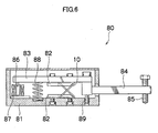
- Fig. 6 shows an example of an application of the rocking fulcrum member 10 in accordance with the present invention to a rocking fulcrum for a measuring head 80.
- the measuring head 80 one of the L-shaped flat plate portions of the rocking fulcrum member 10 is screwed to a measuring head body 81 by using the three attachment holes 10G and an attachment plate 82 having three threaded holes, as shown in Fig. 6.
- An arm member 83 is screwed to the other L-shaped flat plate portion of the rocking fulcrum member 10 by using another attachment plate 82.
- a finger 84 is attached to a fore end of the arm member 83.
- a contactor 85 is attached to a tip of the finger 84.
- a core 86 of a differential transformer is attached to a rear end of the arm member 83.
- a coil 87 of the differential transformer is attached to the measuring head body 81.
- a compression coil spring 88 is provided between the measuring head body 81 and the arm member 83 to apply a measuring pressure to the contactor 85.
- a stopper screw provided in the measuring head body 81 is used to set a rocking lower end of the arm member 83.
- the arm member 83 seesaws on the crisscross spring fulcrum formed by the rocking fulcrum member 10. The amount of movement of the contactor 85 when the contactor 85 is in contact with a work is detected with the differential transformer, thus making an accurate measurement.
- the rocking fulcrum member 10 is a press-formed crisscross spring fulcrum member integrally formed as described above. Therefore, the rocking fulcrum member 10 can be manufactured at a low cost and easily mounted, are free from variations in crisscross spring fulcrum characteristic due to variations in the mounted state and can be suitably used as a precise rocking fulcrum.
- the crisscross spring in which the surfaces of the first elastic plate spring portion 10A and the second elastic plate spring portion 10B cross each other at right angles is formed.
- the crisscross spring in which the surfaces of the first elastic plate spring portion 20A, the third elastic plate spring portion 20H and the second elastic plate spring portion 20B cross each other at right angles is formed.
- the crossing angle between these portions in the arrangement of the present invention may be different from 90°.
Landscapes
- Engineering & Computer Science (AREA)
- General Engineering & Computer Science (AREA)
- Mechanical Engineering (AREA)
- Springs (AREA)
- A Measuring Device Byusing Mechanical Method (AREA)
- Sewing Machines And Sewing (AREA)
- Treatment Of Fiber Materials (AREA)
Abstract
Description
Claims (6)
- A rocking fulcrum member (10), comprising:a first elastic plate portion (10A); anda second elastic plate portion (10B) placed on planes intersecting each other to form a crisscross spring (11), characterized in thateach of the first elastic plate portion (10A) and the second elastic plate portion (10B) has extensions (10C, 10E, 10D, 10F) from its one end and the other end in its longitudinal direction;the extension (10C) from the one end of the first elastic plate portion (10A) is bent at an acute angle from the first elastic plate portion (10A), while the extension (10D) from the other end of the first elastic plate portion (10A) is bent at an obtuse angle from the first elastic plate portion (10A);the extension (10E) from the one end of the second elastic plate portion (10B) is bent at an obtuse angle from the second elastic plate portion (10B), while the extension (10F) from the other end of the second elastic plate portion (10B) is bent at an acute angle from the second elastic plate portion (10B);the extension (10C) from the one end of the first elastic plate portion (10A) and the extension (10E) from the one end of the second elastic plate portion (10B) are formed as one continuous member on one plane;the extension (10D) from the other end of the first elastic plate portion (10A) and the extension (10F) from the other end of the second elastic plate portion (10B) are formed as one continuous member on one plane; andthe first elastic plate portion (10A), the extension (10C) from the one end of the first elastic plate portion (10A), the extension (10D) from the other end of the first elastic plate portion (10A), the second elastic plate portion (10B), the extension (10E) from the one end of the second elastic plate portion (10B) and the extension (10F) from the other end of the second elastic plate portion (10B) are a continuous member formed by fabricating one elastic member (50) in the form of a plate.
- The rocking fulcrum member (10) according to claim 1, wherein a width (L1) of the first elastic plate portion (10A) and a width (L2) of the second elastic plate portion (10B) are equal to each other.
- A rocking fulcrum member (20), comprising: a first elastic plate portion (20A), a second elastic plate portion (20B), and a third elastic plate portion (20H), the first elastic plate portion (20A) and the third elastic plate portion (20H) being placed parallel to each other on one plane, the second elastic plate portion (20B) being placed between the first elastic plate portion (20A) and the third elastic plate portion (20H), the first elastic plate portion (20A), the third elastic plate portion (20H) and the second elastic plate portion (20B) being placed on planes intersecting each other to form a crisscross spring (21), characterized in that:each of the first elastic plate portion (20A), the second elastic plate portion (20B) and the third elastic plate portion (20H) has extensions (20C, 20E, 20J, 20D, 20F, 20K) from its one end and the other end in its longitudinal direction;the extension (20C) from the one end of the first elastic plate portion (20A) is bent at an acute angle from the first elastic plate portion (20A), while the extension (20D) from the other end of the first elastic plate portion (20A) is bent at an obtuse angle from the first elastic plate portion (20A);the extension (20E) from the one end of the second elastic plate portion (20B) is bent at an obtuse angle from the second elastic plate portion (20B), while the extension (20F) from the other end of the second elastic plate portion (20B) is bent at an acute angle from the second elastic plate portion (20B);the extension (20J) from the one end of the third elastic plate portion (20H) is bent at an acute angle from the third elastic plate portion (20H), while the extension (20K) from the other end of the third elastic plate portion (20H) is bent at an obtuse angle from the third elastic plate portion (20H);the extension (20C) from the one end of the first elastic plate portion (20A), the extension (20E) from the one end of the second elastic plate portion (20B) and the extension (20J) from the one end of the third elastic plate portion (20H) are formed as one continuous member on one plane;the extension (20D) from the other end of the first elastic plate portion (20A), the extension (20F) from the other end of the second elastic plate portion (20B) and the extension (20K) from the other end of the third elastic plate portion (20H) are formed as one continuous member on one plane; andthe first elastic plate portion (20A), the extension (20C) from the one end of the first elastic plate portion (20A), the extension (20D) from the other end of the first elastic plate portion (20A), the second elastic plate portion (20B), the extension (20E) from the one end of the second elastic plate portion (20B), the extension (20F) from the other end of the second elastic plate portion (20B), the third elastic plate portion (20H), the extension (20J) from the one end of the third elastic plate portion (20H) and the extension (20K) from the other end of the third elastic plate portion (20H) are a continuous member formed by fabricating one elastic member (60) in the form of a plate.
- The rocking fulcrum member (20) according to claim 3, wherein sum of a width (L3) of the first elastic plate portion (20A) and a width (L5) of the third elastic plate portion (20H) is equal to a width (L4) of a second elastic plate portion.
- The rocking fulcrum member (10, 20) according to any one of claims 1 to 4, wherein an attachment hole (10G, 20G) for attachment of a member is formed in each of the continuous member on one plane in which the extension from the one end of each elastic plate portion is formed and the continuous member on one plane in which the extension from the other end of each elastic plate portion is formed.
- The rocking fulcrum member (10, 20) according to any one of claims 1 to 5, wherein a heat treatment is performed on the crisscross spring (11, 21) formed by fabricating the one elastic member (50, 60) in the form of a plate.
Applications Claiming Priority (2)
| Application Number | Priority Date | Filing Date | Title |
|---|---|---|---|
| JP2004058989A JP4207808B2 (en) | 2004-03-03 | 2004-03-03 | Swing fulcrum member |
| JP2004058989 | 2004-03-03 |
Publications (2)
| Publication Number | Publication Date |
|---|---|
| EP1571355A2 true EP1571355A2 (en) | 2005-09-07 |
| EP1571355A3 EP1571355A3 (en) | 2010-07-07 |
Family
ID=34747643
Family Applications (1)
| Application Number | Title | Priority Date | Filing Date |
|---|---|---|---|
| EP05004489A Withdrawn EP1571355A3 (en) | 2004-03-03 | 2005-03-01 | Rocking fulcrum member |
Country Status (3)
| Country | Link |
|---|---|
| US (1) | US7370841B2 (en) |
| EP (1) | EP1571355A3 (en) |
| JP (1) | JP4207808B2 (en) |
Families Citing this family (4)
| Publication number | Priority date | Publication date | Assignee | Title |
|---|---|---|---|---|
| JP4299826B2 (en) * | 2005-11-30 | 2009-07-22 | 株式会社住田光学ガラス | White light emitting device using fluorescent fiber |
| DE102006040213C5 (en) * | 2006-01-19 | 2019-08-01 | Bcs Automotive Interface Solutions Gmbh | Retaining clip for a rain sensor |
| DE102006023714B4 (en) | 2006-05-19 | 2008-04-17 | Dräger Safety AG & Co. KGaA | Apparatus and method for selectively determining the amount of oil mist |
| JP2024067654A (en) * | 2022-11-07 | 2024-05-17 | 株式会社東京精密 | Measuring head and swing support member used therein |
Family Cites Families (7)
| Publication number | Priority date | Publication date | Assignee | Title |
|---|---|---|---|---|
| US3807029A (en) * | 1972-09-05 | 1974-04-30 | Bendix Corp | Method of making a flexural pivot |
| US4402118A (en) * | 1981-09-28 | 1983-09-06 | Usm Corporation | Clip for securing a panel to a support |
| US5526553A (en) * | 1994-10-24 | 1996-06-18 | Unisys Corporation | Snap-lock spring clip attachment system |
| US5709574A (en) * | 1996-08-30 | 1998-01-20 | Autosplice Systems Inc. | Surface-mountable socket connector |
| IT1286749B1 (en) | 1996-11-07 | 1998-07-17 | Marposs Spa | HEAD FOR THE CONTROL OF LINEAR DIMENSIONS OF MECHANICAL PIECES |
| US6051781A (en) * | 1997-09-24 | 2000-04-18 | Autosplice, Inc. | Surface mount electromagnetic frequency interference shield clip |
| USD516904S1 (en) * | 2003-12-29 | 2006-03-14 | Kendrick Kathleen S | Clip |
-
2004
- 2004-03-03 JP JP2004058989A patent/JP4207808B2/en not_active Expired - Fee Related
-
2005
- 2005-03-01 EP EP05004489A patent/EP1571355A3/en not_active Withdrawn
- 2005-03-02 US US11/068,918 patent/US7370841B2/en not_active Expired - Fee Related
Also Published As
| Publication number | Publication date |
|---|---|
| JP2005249038A (en) | 2005-09-15 |
| US7370841B2 (en) | 2008-05-13 |
| EP1571355A3 (en) | 2010-07-07 |
| JP4207808B2 (en) | 2009-01-14 |
| US20050194504A1 (en) | 2005-09-08 |
Similar Documents
| Publication | Publication Date | Title |
|---|---|---|
| EP1402563B1 (en) | Interposer assembly and method | |
| JP5180445B2 (en) | Test socket | |
| KR101948401B1 (en) | Probe pin | |
| JP4109673B2 (en) | Contact probe with an opening away from the center position drilled through the back | |
| EP1571355A2 (en) | Rocking fulcrum member | |
| US10724593B2 (en) | Torsion spring | |
| JPH02500786A (en) | electromagnetic relay | |
| US4539545A (en) | Thermal switch | |
| EP1777423B1 (en) | Pivot joint | |
| US4051453A (en) | Variable resistance control with low noise contactor | |
| JP6633203B2 (en) | Variable resistor | |
| JP3203580U (en) | Optical element holding mechanism | |
| JPH11162545A (en) | Connector for electric connection | |
| CN213581052U (en) | Crimping mechanism and testing arrangement | |
| JP2004061194A (en) | Contact probe device | |
| US3957334A (en) | Printed circuit board array for card reader | |
| US4365123A (en) | Snap switch as well as a method for its manufacture | |
| KR102431300B1 (en) | Connection Pin For High Current Carrying | |
| CN114296513B (en) | Touch panel mechanism for electronic products and assembly method thereof | |
| JP3539860B2 (en) | Mounting structure of watch contact plate | |
| JPH076576Y2 (en) | Push switch | |
| JP4908048B2 (en) | Relay contact arrangement | |
| US20020000906A1 (en) | Resistor array board | |
| JPH0789462B2 (en) | Lag switch | |
| JP2010176953A (en) | Relay connector |
Legal Events
| Date | Code | Title | Description |
|---|---|---|---|
| PUAI | Public reference made under article 153(3) epc to a published international application that has entered the european phase |
Free format text: ORIGINAL CODE: 0009012 |
|
| AK | Designated contracting states |
Kind code of ref document: A2 Designated state(s): AT BE BG CH CY CZ DE DK EE ES FI FR GB GR HU IE IS IT LI LT LU MC NL PL PT RO SE SI SK TR |
|
| AX | Request for extension of the european patent |
Extension state: AL BA HR LV MK YU |
|
| PUAL | Search report despatched |
Free format text: ORIGINAL CODE: 0009013 |
|
| AK | Designated contracting states |
Kind code of ref document: A3 Designated state(s): AT BE BG CH CY CZ DE DK EE ES FI FR GB GR HU IE IS IT LI LT LU MC NL PL PT RO SE SI SK TR |
|
| AX | Request for extension of the european patent |
Extension state: AL BA HR LV MK YU |
|
| STAA | Information on the status of an ep patent application or granted ep patent |
Free format text: STATUS: THE APPLICATION IS DEEMED TO BE WITHDRAWN |
|
| AKY | No designation fees paid | ||
| 18D | Application deemed to be withdrawn |
Effective date: 20101001 |
|
| REG | Reference to a national code |
Ref country code: DE Ref legal event code: R108 Effective date: 20110301 Ref country code: DE Ref legal event code: 8566 |