EP1571323A2 - Cylinder head with improved heat transfer and valve seat cooling - Google Patents
Cylinder head with improved heat transfer and valve seat cooling Download PDFInfo
- Publication number
- EP1571323A2 EP1571323A2 EP05003542A EP05003542A EP1571323A2 EP 1571323 A2 EP1571323 A2 EP 1571323A2 EP 05003542 A EP05003542 A EP 05003542A EP 05003542 A EP05003542 A EP 05003542A EP 1571323 A2 EP1571323 A2 EP 1571323A2
- Authority
- EP
- European Patent Office
- Prior art keywords
- wall
- fire
- exhaust port
- chamber
- coolant
- Prior art date
- Legal status (The legal status is an assumption and is not a legal conclusion. Google has not performed a legal analysis and makes no representation as to the accuracy of the status listed.)
- Withdrawn
Links
Images



Classifications
-
- F—MECHANICAL ENGINEERING; LIGHTING; HEATING; WEAPONS; BLASTING
- F02—COMBUSTION ENGINES; HOT-GAS OR COMBUSTION-PRODUCT ENGINE PLANTS
- F02F—CYLINDERS, PISTONS OR CASINGS, FOR COMBUSTION ENGINES; ARRANGEMENTS OF SEALINGS IN COMBUSTION ENGINES
- F02F1/00—Cylinders; Cylinder heads
- F02F1/24—Cylinder heads
- F02F1/26—Cylinder heads having cooling means
- F02F1/36—Cylinder heads having cooling means for liquid cooling
- F02F1/38—Cylinder heads having cooling means for liquid cooling the cylinder heads being of overhead valve type
-
- F—MECHANICAL ENGINEERING; LIGHTING; HEATING; WEAPONS; BLASTING
- F01—MACHINES OR ENGINES IN GENERAL; ENGINE PLANTS IN GENERAL; STEAM ENGINES
- F01P—COOLING OF MACHINES OR ENGINES IN GENERAL; COOLING OF INTERNAL-COMBUSTION ENGINES
- F01P3/00—Liquid cooling
- F01P3/02—Arrangements for cooling cylinders or cylinder heads
-
- F—MECHANICAL ENGINEERING; LIGHTING; HEATING; WEAPONS; BLASTING
- F02—COMBUSTION ENGINES; HOT-GAS OR COMBUSTION-PRODUCT ENGINE PLANTS
- F02F—CYLINDERS, PISTONS OR CASINGS, FOR COMBUSTION ENGINES; ARRANGEMENTS OF SEALINGS IN COMBUSTION ENGINES
- F02F1/00—Cylinders; Cylinder heads
- F02F1/24—Cylinder heads
- F02F1/26—Cylinder heads having cooling means
- F02F1/36—Cylinder heads having cooling means for liquid cooling
- F02F1/40—Cylinder heads having cooling means for liquid cooling cylinder heads with means for directing, guiding, or distributing liquid stream
-
- F—MECHANICAL ENGINEERING; LIGHTING; HEATING; WEAPONS; BLASTING
- F01—MACHINES OR ENGINES IN GENERAL; ENGINE PLANTS IN GENERAL; STEAM ENGINES
- F01P—COOLING OF MACHINES OR ENGINES IN GENERAL; COOLING OF INTERNAL-COMBUSTION ENGINES
- F01P3/00—Liquid cooling
- F01P3/02—Arrangements for cooling cylinders or cylinder heads
- F01P2003/024—Cooling cylinder heads
-
- F—MECHANICAL ENGINEERING; LIGHTING; HEATING; WEAPONS; BLASTING
- F01—MACHINES OR ENGINES IN GENERAL; ENGINE PLANTS IN GENERAL; STEAM ENGINES
- F01P—COOLING OF MACHINES OR ENGINES IN GENERAL; COOLING OF INTERNAL-COMBUSTION ENGINES
- F01P3/00—Liquid cooling
Definitions
- the present invention relates to internal combustion diesel engines, and more particularly to a cylinder head improved over that disclosed in U.S. Patent 4,860,700, wherein a plurality of consequential modifications provide improved heat transfer and valve seat cooling with respect to circulating coolant of a coolant system of the engine.
- Numeral 10 generally indicates a cylinder head of the general type shown in U.S. Patent 3,377,996 Kotlin et al, but having significant differences in the cooling water jacket structure as will be subsequently more fully described.
- the cylinder head embodiment disclosed when assembled with the usual valve mechanism, not shown, is primarily intended for use in a uniflow scavenged two-cycle engine of the fuel injection compression ignition type and is adapted to be secured in end sealing engagement to the upper end of a jacketed liquid cooled cylinder liner and to be mounted therewith in a cylinder mounting bore of an engine frame member wherein the cylinder head 10 cooperates with a piston reciprocably mounted in the liner to define an expansible combustion chamber therebetween.
- the cylinder head 10 comprises a lower combustion chamber defining fire-face wall 12 engageable outwardly with the upper end of the associated jacketed liner.
- An upper head wall 14 extends in spaced parallel relation to the fire-face wall 12 and is connected thereto by a peripheral boundary sidewall 16.
- a flange 18 is coextensive with and extends upwardly and outwardly of the upper head wall 14 and the sidewall 16 to provide an annular shoulder 20. In mounting the cylinder assembly, this flange defined shoulder of the cylinder head is engageable with a mating shoulder provided therefor in the engine frame.
- the sidewall 16 and flange 18 are structurally reinforced by a plurality of spaced vertically extending stud bosses 22, 23, 24, 25, 26, 27, 28 and 29.
- the stud bosses 22-29 define a plurality of stud holes 30 which are adapted to receive therethrough studs for securing the cylinder head to the jacketed cylinder liner.
- the upper head wall and fire-face wall are interconnected centrally of the cylinder head by a sleeve defining wall portion 32.
- the sleeve defining wall portion 32 provides a central opening 33 extending through the cylinder head which is of stepped and tapered diameters and is adapted to mount a suitable fuel injection device.
- valve seat defining exhaust ports 34 extend through the fire-face 12 of the head in equispaced relation about the sleeve defining wall portion 32.
- the exhaust ports 34 communicate upwardly through short branch passages 35, 36, 37 and 38 with a common exhaust passage or chamber 39.
- the branch passages are defined by exhaust port wall portions 41, 42, 43 and 44 which extend upwardly between the fire-face wall 12 and a horizontal chamber wall 45.
- the chamber wall 45 extends inwardly from the sidewall 16 in spaced parallel relation above the fire-face wall 12, wherein an inner chamber wall surface 45a thereof faces an inner fire-face wall surface 12a of the fire-face wall, and terminates inwardly at its intersection with the sleeve defining wall portion 32.
- the exhaust passage 39 is defined between the chamber wall 45 and an upper passage wall 47.
- the upper passage wall 47 is structurally connected to the upper head wall 14 by four tubular or cylindrical wall portions 48 which extend therebetween in axial alignment with the several valve seating ports 34 and define bores 49 adapted to receive suitable valve guide bushings.
- the exhaust passage 39 extends arcuately of the head, partially embracing the sleeve defining wall portion in spaced relation thereto and intersecting the several valve controllable branch passages 35-38, and communicates laterally outwardly with an exhaust outlet port 50 opening through the sidewall 16 of the head.
- the outlet port 50 is connectable to an exhaust manifold through a suitable branch passage which may be provided in the engine frame.
- the outlet port is vertically intersected by two struts 51 and 52. These struts are co-extensive with stud bosses 22 and 29 respectively and each has a passage 54 extending therethrough.
- the passages 54 permit the circulation of a coolant (i.e., cooling fluid) through the gas exposed struts 51 and 52.
- the chamber and exhaust passage defining walls cooperate with the outer walls of the cylinder head to define a coolant-receiving compartment.
- This compartment is divided by the horizontal chamber wall 45 into a lower jacket chamber 55 and an upper jacket chamber 56.
- the lower jacket chamber 55 is divided by the partition walls 46 into four sections 58, 59, 60 and 61 which are alternately outlet and inlet sections that are interconnected by restricted passages 62 formed between the exhaust port wall portions 41, 42, 43 and 44 and the sleeve defining wall portion 32.
- the upper and lower jacket chambers are interconnected through various openings in chamber wall 45 adjacent the inner periphery of sidewall 16.
- the primary connection is through a pair of relatively large passages 64 extending from the outlet sections 58 and 60 of the lower chamber upwardly past the upper exhaust passage wall 47 to the upper chamber.
- the chambers are also connected through four small openings or coolant by-pass ports 65 connecting with inlet section 59 and passages 54 in struts 51 and 52 which connect with inlet section 61 of the lower chamber.
- the coolant is forced or drawn upwardly into the cylinder head through twelve inlet ports extending through and spaced around the fire-face wall 12 adjacent sidewall 16. Eight of these are relatively large coolant inlet ports 66 which open into inlet sections 59 and 61 of the lower chamber while four are relatively small coolant inlet ports 68 opening into outlet sections 58 and 60 of the lower chamber.
- the coolant inlet ports 66 and 68 mate with corresponding coolant ports provided in the jacketed cylinder liner structure which is connected in a conventional manner to the discharge of a coolant circulation pump.
- the upper flange portion 18 has an outlet passage 69 opening inwardly on the upper chamber 56 and outwardly on a machined face 70 thereof. This outlet passage is connectable through a suitable fitting through coolant outlet manifold to the inlet of the coolant circulation pump in a conventional manner so that forced circulation of coolant through the cylinder head is provided.
- a plurality of cooling spines 71 are disposed on the inner fire-face wall surface 12a thereof, which are distributed among the four sections of the lower chamber over surface area located between the exhaust branch passages 35-38 (or the exhaust port wall portions 41-44) and extending radially outwardly therefrom.
- Additional web members are provided in the lower chamber for supporting the chamber wall 45 including a pair of radially directed members 72 disposed in sections 58 and 60 and a radially directed rib 74 in section 61 which intersects wall 16 and includes an opening 75 for permitting the equalization of coolant flow.
- a radial member 76 extending from a diagonal boss 78 which is located in section 59 and encloses a cylinder test passage 79.
- the outer ends of the partition walls 46 connect with adjacent ones of the stud bosses 22-29, specifically numbers 23, 24, 27 and 28, in a manner such that they also lie tangent to these stud bosses on their sides facing toward the inlet sections 59, 61 of the lower jacket chamber.
- the velocity of the coolant is accelerated due to the constricted passages between the exhaust port wall portions 41-44 as well as between the sleeve defining wall portion 32 and the various branch passage walls; the cooling spines 71, located between the branch passage walls, further accelerate the flow and increase turbulence to obtain a high degree of scrubbing action and very efficient cooling; and the small inlet openings 68, provided in sections 58 and 60, pass a very small percentage of coolant flow into the head and serve to prevent the existence of hot spots in the connected cylinder liner.
- coolant by-pass ports 64 Upon passing upwardly through coolant by-pass ports 64 into the upper chamber, the coolant sweeps over the exhaust passage defining wall 47 and around the outer peripheries of the sleeve defining wall portion 32 and valve guide wall portions 48 before leaving the upper chamber through outlet passage 69.
- a restricted flow of coolant is also permitted to pass directly from chamber 59 through the coolant by-pass ports 65 in partition wall 45 and into the upper jacket chamber.
- the coolant by-pass ports 65 allow removal of coolant from the adjacent portions of the cylinder head when the engine cooling system is drained.
- a small flow of coolant is permitted to pass from section 61 of the lower jacket chamber through restrictive openings 80 in passages 54 to cool the struts 51 and 52 as well as prevent stagnation in the upper chamber.
- the modified tangential positioning of the partition walls 46 avoids the creation of stagnant pockets of coolant, particularly on the outlet section sides of the partition walls between the exhaust port wall portions 41-44 and the outer peripheral sidewall 16, wherein the coolant flow entering the outlet sections from the passages 62 is encouraged to flow directly along the surfaces of the partition walls 46, cooling the metal surfaces by its scrubbing action and avoiding hot spots which might be caused by stagnation if the coolant was directed past recesses or pockets in the jacket construction.
- the present invention is a cylinder head improved over the cylinder head disclosed in U.S. Patent 4,860,700, wherein the improvement relates to a plurality of consequential structural modifications which provide improved heat transfer and valve seat cooling.
- the improved cylinder head according to the present invention is a cylinder head having structural aspects as described in U.S. Patent 4,860,700 and as recounted hereinabove, wherein structural modification of consequential nature have been made thereto in order to provide improved heat transfer to the coolant and improved, uniform valve seat cooling.
- structural modification of consequential nature have been made thereto in order to provide improved heat transfer to the coolant and improved, uniform valve seat cooling.
- the first consequential structural modification is intended to eliminate stagnant coolant at the partition walls and to provide coolant flow all around the valve seats so as to provide more uniform valve seat cooling.
- the first consequential structural modification involves a coolant by-pass opening formed in each of the partition walls adjacent the exhaust port wall portions, wherein now the coolant by-pass openings separate the partition walls from the exhaust port wall portions.
- the second consequential structural modification is intended to address the inability of the densely arranged spines on the inner side of the fire-face wall to effectively transfer heat to the coolant.
- the second consequential structural modification involves eliminating or loosely arranging the spines, or otherwise providing undulations on the inner side of the fire-face wall so that heat transfer to the coolant is improved.
- the third consequential structural modification is intended to address the inadequacy of the coolant flow at the inner side of the fire-face wall.
- the third consequential structural modification involves locating the inner chamber wall surface closer to the inner fire-face surface so that coolant flows in better relation to the inner fire-face wall surface so as to improve extraction heat therefrom.
- the fourth consequential structural modification is intended to address an excessive amount of coolant bypassing to the upper jacket chamber from the lower jacket chamber, with consequent lowering of coolant flow in the lower jacket chamber through the coolant by-pass ports.
- the fourth consequential structural modification involves reducing the diameter of the coolant by-pass ports to an acceptably minimum so that coolant flow in the lower jacket is improved.
- the fifth consequential structural modification is intended to address structural stiffness in the area of the radial rib.
- the fifth consequential structural modification involves the radial rib being extended or completed, wherein the opening therein as recounted hereinabove is eliminated, so that structural stiffness is improved which, in turn, provides an improvement of gasket reliability at the cylinder head to cylinder liner interface.
- Figure 1 is a top elevational view of a prior art cylinder head according to U.S. Patent 4,860,700.
- Figures 2 and 3 are vertical sectional views taken substantially in the planes of the lines indicated at 2-2 and 3-3 respectively of Figure 1.
- Figure 4 is a vertical sectional view taken substantially in the plane indicated by the line 4-4 of Figure 2.
- Figures 5, 6, and 7 are horizontal sectional views taken substantially in the planes indicated by the lines 5-5, 6-6 and 7-7 respectively of Figure 2.
- Figure 8 is a sectional view taken along line 8-8 of Figure 5.
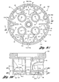
- Figure 9A is a first cross-sectional view of a cylinder head according to a first preferred embodiment of the present invention.
- Figure 9B is a second cross-sectional view of a cylinder head according to the present invention.
- Figure 10 is a cross-sectional view, taken along line 10-10 of Figure 9A, wherein the sectional view of Figure 9A is taken along line 9A-9A of Figure 10, and wherein the sectional view of Figure 9B is taken along line 9B-9B of Figure 10.
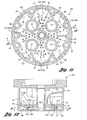
- Figure 11 is a cross-sectional view of a cylinder head according to a second preferred embodiment of the present invention.
- Figure 12 is a cross-sectional view taken along line 12-12 of Figure 11, and wherein the sectional view of Figure 11 was taken along line 11-11 of Figure 12.
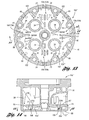
- Figure 13 is a cross-sectional view of a cylinder head according to a third preferred embodiment of the present invention.
- Figure 14 is a cross-sectional view, taken along line 14-14 of Figure 13, and wherein the sectional view of Figure 13 was taken along line 13-13 of Figure 14.
- Figures 1 through 8 depict a prior art cylinder head according to the disclosure in U.S. Patent 4,860,700
- Figures 9 through 14 depict an improved cylinder head according to the present invention, wherein the cylinder head of the present invention involves five consequential modifications of the cylinder head of U.S. Patent 4,860,700
- the disclosure recounted respecting Figures 1 through 8 is, for the sake of brevity, incorporated hereinbelow, with like numbers representing like parts, the exceptions thereto relating to the aforesaid five consequential structural modification being as noted by the same numbers with primes or by new numbers.
- FIG. 1 a first preferred embodiment of an improved cylinder head 100 is depicted, wherein the five consequential structural modifications, a first consequential modification 102, a second consequential modification 104, a third consequential modification 106, a fourth consequential modification 108, and a fifth consequential modification 110, are shown, and wherein a first aspect 104a of the second consequential modification 104 is depicted.
- the first consequential structural modification 102 of the improved cylinder head 100 involves a coolant by-pass opening 112 formed in each of the partition walls 46' adjacent the exhaust port wall portions 41, 42, 43, 44 whereat is situated the valve seats.
- the coolant by-pass openings 112 are located at the exhaust port wall portions 41-44 and serve to separate the partition walls 46' from the exhaust port wall portions 41-44 so that coolant is able to flow freely all around the exhaust port wall portions.
- the coolant by-pass openings 112 eliminate any possibility for stagnant coolant at the partition walls and provide coolant flow all around the exhaust port wall portions (valve seats) to provide uniform valve seat cooling.
- the first consequential modification 102 may be effected any of several ways, including: when casting, including the by-pass opening in the partition walls 46'; drilling a small hole on each of the uninterrupted partition walls 46; using a fusible steel passage in the castings on each partition wall location; or any other technique to allow coolant to flow through the partition walls and thereby flow all around the exhaust port wall portions (valve seats).
- a pair of obstructions 114 may be added on either side of the coolant by-pass openings 112 so as to optimize coolant flow through the coolant by-pass openings.
- the second consequential structural modification 104 of the improved cylinder head 100 involves, according to a first aspect 104a thereof, eliminating the spines (see 71 in Figure 8) so that heat transfer to the coolant is improved with respect to the inner side 12a' of the fire-face wall 12'.
- CFD computational fluid dynamic
- the third consequential structural modification 106 of the improved cylinder head 100 involves locating the inner partition wall surface 45a' closer to the inner fire-face wall surface 12a' so that coolant flows in better relation to the inner fire-face wall surface to improve extraction of heat therefrom.
- the fourth consequential structural modification 108 of the improved cylinder head 100 involves reducing the diameter of the coolant by-pass ports 65' to an acceptable minimum so that coolant flow in the lower jacket chamber 55 is improved.
- reducing the diameter of the coolant by-pass ports in the present invention a problem was remedied with respect to the cylinder head of U.S. Patent 4,860,700 (see comparison between coolant by-pass ports 65, 65' respectively of Figures 8 and 9), wherein an excessive amount of coolant bypassing to the upper jacket chamber from the lower jacket chamber with consequent lowering of coolant flow in the lower jacket chamber.
- the coolant by-pass ports are twenty-five percent to seventy-five percent the diameter of the by-pass ports disclosed in U.S. Patent 4,860,700; that is, the coolant by-pass ports 65' of the present invention have a cross-section of substantially between 0.1875 inches and 0.0625 inches, as compared to a cross-section of about 0.25 inches for the coolant by-pass ports 65 of U.S. Patent 4,860,700.
- the fifth consequential structural modification 110 of the improved cylinder head 100 involves the radial rib 74' being extended (or completed), wherein the opening 75 of Figure 5 is eliminated (see comparison between Figures 5 and 9).
- the radial rib 74' complete structural stiffness is improved which, in turn, provides an improvement of gasket reliability at the cylinder head to cylinder liner interface. Additionally, coolant flow is improved in the region of the completed radial rib 74'.
- FIG. 11 a second embodiment of the improved cylinder head 100' according to the present invention is shown, wherein the aforedescribed first, third, fourth and fifth consequential modifications 102, 106, 108, 110 remain as depicted and hereinabove described, but wherein a second aspect 104b of the second consequential modification 104 is depicted.
- the spines 71 are provided on the inner fire-face wall surface 12a", but in a much looser (or more widely spaced) arrangement than the densely packed arrangement shown in Figures 5 and 8.
- coolant is able to circulate therethrough, with little or no flow over, so that heat transfer from the fire-face wall to the coolant is improved over that attainable in the disclosure of U.S. Patent 4,860,700.
- the density of packing of the spines 71 is preferred to be between zero and fifty percent of the density of packing disclosed in U.S.
- Patent 4,860,700 that is, in the present invention the density of the spines 71 is less than substantially five spines per square inch, wherein by way of comparison, the density of the spines for the cylinder head of U.S. Patent 4,860,700 is about 9.8 spines per square inch.
- FIG. 13 a third embodiment of the improved cylinder head 100" according to the present invention is shown, wherein the aforedescribed first, third, fourth and fifth consequential modifications 102, 106, 108, 110 remain as depicted and hereinabove described, but wherein a third aspect 104c of the second consequential modification 104 is depicted.
- undulations 71' are provided on the inner fire-face wall surface 12a"'.
- the undulations may be, for example waves (as shown) or may be dimples.
- the undulations 71' increase the surface area in contact with the coolant and thereby provide improved heat transfer from the fire-face wall to the coolant over that attainable in the disclosure of U.S. Patent 4,860,700.
Landscapes
- Engineering & Computer Science (AREA)
- Chemical & Material Sciences (AREA)
- Combustion & Propulsion (AREA)
- Mechanical Engineering (AREA)
- General Engineering & Computer Science (AREA)
- Cylinder Crankcases Of Internal Combustion Engines (AREA)
Abstract
Description
Claims (19)
- In a diesel engine cylinder head comprising:wherein an improvement thereto comprises:a sidewall;a coolant jacket within said sidewall;a fire-face wall having an inner fire-face wall surface, said fire-face wall having a periphery connected to said sidewall;a chamber wall extending generally parallel to said fire-face wall in substantially spaced relation thereto, said spacing being substantially 0.89 inches, said chamber wall having an inner chamber wall surface facing said inner fire-face wall surface, said fire-face wall and said chamber wall collectively dividing said coolant jacket into a lower jacket chamber and an upper jacket chamber;a plurality of exhaust port wall portions extending through said coolant receiving jacket and embracing a portion of said fire-face wall, each exhaust port wall portion of said plurality of exhaust port wall portions defining a respective valve controllable exhaust port opening through said fire-face wall;a plurality of stud bosses located adjacent said sidewall and in spaced relation with respect to said plurality of exhaust port wall portions;a plurality of partition walls in said lower jacket chamber, one partition wall for each exhaust port wall portion, wherein each partition wall extends outwardly in substantially tangent relation from its respective exhaust port wall portion and connects with a respective stud boss;a plurality of coolant inlet ports formed in said fire-face wall and opening into said lower jacket chamber adjacent a periphery thereof;a plurality of coolant by-pass ports formed in said chamber wall fluidically connecting said lower jacket chamber to said upper jacket, said by-pass ports having a cross-section of substantially 0.25 inches;a plurality of densely packed spines located at said inner fire-face wall surface substantially adjacent said plurality of exhaust port wall portions, wherein the spines have a density of substantially 9.8 spines per square inch; anda radial rib connected with said fire-face wall and said sidewall, said rib having a rib opening formed therein;a coolant by-pass opening formed in each partition wall adjacent its respective exhaust port wall portion;a spine density of substantially less than five spines per square inch;spacing said inner chamber wall surface with respect to said inner fire-face wall surface substantially between 0.75 inches and 0.25 inches;said by-pass ports having a cross-section of substantially between 0.1875 inches and 0.0625 inches; andsaid radial rib extending complete and free of said rib opening.
- The cylinder head of claim 1, further comprising a plurality of obstructions respectively adjacent each said by-pass opening of each said partition wall.
- The cylinder head of Claim 1, wherein said inner fire-face wall surface is free of said spines.
- The cylinder head of claim 3, further comprising a plurality of obstructions respectively adjacent each said by-pass opening of each said partition wall.
- The cylinder head of Claim 3, further comprising a plurality of undulations located at said inner fire-face wall surface substantially adjacent said plurality of exhaust port wall portions.
- The cylinder head of claim 5, further comprising a plurality of obstructions respectively adjacent each said by-pass opening of each said partition wall.
- In a diesel engine cylinder head comprising:a sidewall;a coolant jacket within said sidewall;a fire-face wall having an inner fire-face wall surface, said fire-face wall having a periphery connected to said sidewall;a chamber wall extending generally parallel to said fire-face wall in substantially spaced relation thereto, said spacing being substantially 0.89 inches, said chamber wall having an inner chamber wall surface facing said inner fire-face wall surface, said fire-face wall and said chamber wall collectively dividing said coolant jacket into a lower jacket chamber and an upper jacket chamber;a plurality of exhaust port wall portions extending through said coolant receiving jacket and embracing a portion of said fire-face wall, each exhaust port wall portion of said plurality of exhaust port wall portions defining a respective valve controllable exhaust port opening through said fire-face wall;a plurality of stud bosses located adjacent said sidewall and in spaced relation with respect to said plurality of exhaust port wall portions;a plurality of partition walls in said lower jacket chamber, one partition wall for each exhaust port wall portion, wherein each partition wall extends outwardly in substantially tangent relation from its respective exhaust port wall portion and connects with a respective stud boss;a plurality of coolant inlet ports formed in said fire-face wall and opening into said lower jacket chamber adjacent a periphery thereof;a plurality of coolant by-pass ports formed in said chamber wall fluidically connecting said lower jacket chamber to said upper jacket, said by-pass ports having a cross-section of substantially 0.25 inches;a plurality of densely packed spines located at said inner fire-face wall surface substantially adjacent said plurality of exhaust port wall portions,
wherein the spines have a density of substantially 9.8 spines per square inch; anda radial rib connected with said fire-face wall and said sidewall, said rib having a rib opening formed therein;
wherein an improvement thereto comprises:a by-pass opening formed in each partition wall adjacent its respective exhaust port wall portion. - The cylinder head of claim 7, further comprising a plurality of obstructions respectively adjacent each said by-pass opening of each said partition wall.
- The cylinder head of Claim 7, wherein said improvement further comprises at least one of:a spine density of substantially less than 5 spines per square inch;spacing said inner chamber wall surface with respect to said inner fire-face wall surface substantially between 0.75 inches and 0.25 inches;said coolant by-pass ports having a cross-section of substantially between 0.1875 inches and 0.0625 inches; andsaid radial rib extending complete and free of said rib opening.
- In a diesel engine cylinder head comprising:a sidewall;a coolant jacket within said sidewall;a fire-face wall having an inner fire-face wall surface, said fire-face wall having a periphery connected to said sidewall;a chamber wall extending generally parallel to said fire-face wall in substantially spaced relation thereto, said spacing being substantially 0.89 inches, said chamber wall having an inner chamber wall surface facing said inner fire-face wall surface, said fire-face wall and said chamber wall collectively dividing said coolant jacket into a lower jacket chamber and an upper jacket chamber;a plurality of exhaust port wall portions extending through said coolant receiving jacket and embracing a portion of said fire-face wall, each exhaust port wall portion of said plurality of exhaust port wall portions defining a respective valve controllable exhaust port opening through said fire-face wall;a plurality of stud bosses located adjacent said sidewall and in spaced relation with respect to said plurality of exhaust port wall portions;a plurality of partition walls in said lower jacket chamber, one partition wall for each exhaust port wall portion, wherein each partition wall extends outwardly in substantially tangent relation from its respective exhaust port wall portion and connects with a respective stud boss;a plurality of coolant inlet ports formed in said fire-face wall and opening into said lower jacket chamber adjacent a periphery thereof;a plurality of coolant by-pass ports formed in said chamber wall fluidically connecting said lower jacket chamber to said upper jacket, said by-pass ports having a cross-section of substantially 0.25 inches;a plurality of densely packed spines located at said inner fire-face wall surface substantially adjacent said plurality of exhaust port wall portions, wherein the spines have a density of substantially 9.8 spines per square inch; anda radial rib connected with said fire-face wall and said sidewall, said rib having a rib opening formed therein;
wherein an improvement thereto comprises:a spine density of less than substantially 5 spines per square inch. - The cylinder head of Claim 10, wherein said inner fire-face wall surface is free of said spines.
- The cylinder head of Claim 11, further comprising a plurality of undulations located at said inner fire-face wall surface substantially adjacent said plurality of exhaust port wall portions.
- The cylinder head of Claim 10, wherein said improvement further comprises at least one of:a by-pass opening formed in each partition wall adjacent its respective exhaust port wall portion;spacing said inner chamber wall surface with respect to said inner fire-face wall surface substantially between 0.75 inches and 0.25 inches;said coolant by-pass ports having a cross-section of substantially between 0.1875 inches and 0.0625 inches; andsaid radial rib extending complete and free of said rib opening.
- In a diesel engine cylinder head comprising:wherein an improvement thereto comprises:a sidewall;a coolant jacket within said sidewall;a fire-face wall having an inner fire-face wall surface, said fire-face wall having a periphery connected to said sidewall;a chamber wall extending generally parallel to said fire-face wall in substantially spaced relation thereto, said spacing being substantially 0.89 inches, said chamber wall having an inner chamber wall surface facing said inner fire-face wall surface, said fire-face wall and said chamber wall collectively dividing said coolant jacket into a lower jacket chamber and an upper jacket chamber;a plurality of exhaust port wall portions extending through said coolant receiving jacket and embracing a portion of said fire-face wall, each exhaust port wall portion of said plurality of exhaust port wall portions defining a respective valve controllable exhaust port opening through said fire-face wall;a plurality of stud bosses located adjacent said sidewall and in spaced relation with respect to said plurality of exhaust port wall portions;a plurality of partition walls in said lower jacket chamber, one partition wall for each exhaust port wall portion, wherein each partition wall extends outwardly in substantially tangent relation from its respective exhaust port wall portion and connects with a respective stud boss;a plurality of coolant inlet ports formed in said fire-face wall and opening into said lower jacket chamber adjacent a periphery thereof;a plurality of coolant by-pass ports formed in said chamber wall fluidically connecting said lower jacket chamber to said upper jacket, said by-pass ports having a cross-section of substantially 0.25 inches;a plurality of densely packed spines located at said inner fire-face wall surface substantially adjacent said plurality of exhaust port wall portions, wherein the spines have a density of substantially 9.8 spines per square inch; anda radial rib connected with said fire-face wall and said sidewall, said rib having a rib opening formed therein;spacing said inner chamber wall surface with respect to said inner fire-face wall surface substantially between 0.75 inches and 0.0625 inches.
- The cylinder head of Claim 14, wherein said improvement further comprises at least one of:a by-pass opening formed in each partition wall adjacent its respective exhaust port wall portion;a spine density of less than substantially 5 spines per square inch;said coolant by-pass ports having a cross-section of substantially between 0.1875 inches and 0.0625 inches; andsaid radial rib extending complete and free of said rib opening.
- In a diesel engine cylinder head comprising:wherein an improvement thereto comprises:a sidewall;a coolant jacket within said sidewall;a fire-face wall having an inner fire-face wall surface, said fire-face wall having a periphery connected to said sidewall;a chamber wall extending generally parallel to said fire-face wall in substantially spaced relation thereto, said spacing being substantially 0.89 inches, said chamber wall having an inner chamber wall surface facing said inner fire-face wall surface, said fire-face wall and said chamber wall collectively dividing said coolant jacket into a lower jacket chamber and an upper jacket chamber;a plurality of exhaust port wall portions extending through said coolant receiving jacket and embracing a portion of said fire-face wall, each exhaust port wall portion of said plurality of exhaust port wall portions defining a respective valve controllable exhaust port opening through said fire-face wall;a plurality of stud bosses located adjacent said sidewall and in spaced relation with respect to said plurality of exhaust port wall portions;a plurality of partition walls in said lower jacket chamber, one partition wall for each exhaust port wall portion, wherein each partition wall extends outwardly in substantially tangent relation from its respective exhaust port wall portion and connects with a respective stud boss;a plurality of coolant inlet ports formed in said fire-face wall and opening into said lower jacket chamber adjacent a periphery thereof;a plurality of coolant by-pass ports formed in said chamber wall fluidically connecting said lower jacket chamber to said upper jacket, said by-pass ports having a cross-section of substantially 0.25 inches;a plurality of densely packed spines located at said inner fire-face wall surface substantially adjacent said plurality of exhaust port wall portions, wherein the spines have a density of substantially 9.8 spines per square inch; anda radial rib connected with said fire-face wall and said sidewall, said rib having a rib opening formed therein;said coolant by-pass ports having a cross-section of substantially between 0.1875 inches and 0.0625 inches.
- The cylinder head of Claim 16, wherein said improvement further comprises at least one of:a by-pass opening formed in each partition wall adjacent its respective exhaust port wall portion;a spine density of substantially less than 5 spines per square inch;spacing said inner chamber wall surface with respect to said inner fire-face wall surface substantially between 0.75 inches and 0.25 inches; andsaid radial rib extending complete and free of said rib opening.
- In a diesel engine cylinder head comprising:wherein an improvement thereto comprises:a sidewall;a coolant jacket within said sidewall;a fire-face wall having an inner fire-face wall surface, said fire-face wall having a periphery connected to said sidewall;a chamber wall extending generally parallel to said fire-face wall in substantially spaced relation thereto, said spacing being substantially 0.89 inches, said chamber wall having an inner chamber wall surface facing said inner fire-face wall surface, said fire-face wall and said chamber wall collectively dividing said coolant jacket into a lower jacket chamber and an upper jacket chamber;a plurality of exhaust port wall portions extending through said coolant receiving jacket and embracing a portion of said fire-face wall, each exhaust port wall portion of said plurality of exhaust port wall portions defining a respective valve controllable exhaust port opening through said fire-face wall;a plurality of stud bosses located adjacent said sidewall and in spaced relation with respect to said plurality of exhaust port wall portions;a plurality of partition walls in said lower jacket chamber, one partition wall for each exhaust port wall portion, wherein each partition wall extends outwardly in substantially tangent relation from its respective exhaust port wall portion and connects with a respective stud boss;a plurality of coolant inlet ports formed in said fire-face wall and opening into said lower jacket chamber adjacent a periphery thereof;a plurality of coolant by-pass ports formed in said chamber wall fluidically connecting said lower jacket chamber to said upper jacket, said by-pass ports having a cross-section of substantially 0.25 inches;a plurality of densely packed spines located at said inner fire-face wall surface substantially adjacent said plurality of exhaust port wall portions, wherein the spines have a density of substantially 9.8 spines per square inch; anda radial rib connected with said fire-face wall and said sidewall, said rib having a rib opening formed therein;said radial rib extending complete and free of said rib opening.
- The cylinder head of Claim 18, wherein said improvement further comprises at least one of:a by-pass opening formed in each partition wall adjacent its respective exhaust port wall portion;a spine density of less than substantially 5 spines per square inch;spacing said inner chamber wall surface with respect to said inner fire-face wall surface substantially between 0.74 inches and 0.25 inches; andsaid coolant by-pass ports having a cross-section of substantially between 0.1875 inches and 0.0625 inches.
Applications Claiming Priority (4)
| Application Number | Priority Date | Filing Date | Title |
|---|---|---|---|
| US55011404P | 2004-03-04 | 2004-03-04 | |
| US550114P | 2004-03-04 | ||
| US11/041,663 US7086357B2 (en) | 2004-03-04 | 2005-01-24 | Cylinder head with improved heat transfer and valve seat cooling |
| US41663 | 2005-01-24 |
Publications (2)
| Publication Number | Publication Date |
|---|---|
| EP1571323A2 true EP1571323A2 (en) | 2005-09-07 |
| EP1571323A3 EP1571323A3 (en) | 2010-03-24 |
Family
ID=34752606
Family Applications (1)
| Application Number | Title | Priority Date | Filing Date |
|---|---|---|---|
| EP05003542A Withdrawn EP1571323A3 (en) | 2004-03-04 | 2005-02-18 | Cylinder head with improved heat transfer and valve seat cooling |
Country Status (4)
| Country | Link |
|---|---|
| US (1) | US7086357B2 (en) |
| EP (1) | EP1571323A3 (en) |
| CA (1) | CA2497227C (en) |
| MX (1) | MXPA05002187A (en) |
Cited By (4)
| Publication number | Priority date | Publication date | Assignee | Title |
|---|---|---|---|---|
| AT514087B1 (en) * | 2013-07-04 | 2014-10-15 | Avl List Gmbh | Cylinder head for an internal combustion engine |
| CN105392973A (en) * | 2013-05-08 | 2016-03-09 | Avl里斯脱有限公司 | Cylinder head for an internal combustion engine |
| CN107250518A (en) * | 2015-02-17 | 2017-10-13 | 三菱重工业株式会社 | Cylinder head and engine |
| DE102006026130B4 (en) | 2006-06-03 | 2022-09-08 | Mercedes-Benz Group AG | Cylinder head for a liquid-cooled internal combustion engine and method for operating an internal combustion engine |
Families Citing this family (11)
| Publication number | Priority date | Publication date | Assignee | Title |
|---|---|---|---|---|
| US8051810B2 (en) * | 2008-04-21 | 2011-11-08 | Hyundai Motor Company | Coolant passage within a cylinder head of an internal combustion engine |
| US8944018B2 (en) | 2010-07-14 | 2015-02-03 | Ford Global Technologies, Llc | Cooling strategy for engine head with integrated exhaust manifold |
| US8839759B2 (en) | 2010-08-16 | 2014-09-23 | Ford Global Technologies, Llc | Integrated exhaust manifold |
| US8584628B2 (en) | 2010-07-14 | 2013-11-19 | Ford Global Technologies, Llc | Engine with cylinder head cooling |
| US8100117B2 (en) * | 2010-08-16 | 2012-01-24 | Ford Global Technologies, Llc | Method and system for controlling engine exhaust |
| US8134469B2 (en) | 2010-10-27 | 2012-03-13 | Ford Global Technologies, Llc | Wireless fuel level sensor for a vehicle fuel tank |
| US9133800B2 (en) | 2011-08-30 | 2015-09-15 | Electro-Motive Diesel, Inc. | Fuel quill passageway assembly for engine |
| GB2511136B (en) * | 2013-02-26 | 2019-12-04 | Mclaren Automotive Ltd | Engine cooling |
| KR101905947B1 (en) * | 2016-03-16 | 2018-10-10 | 현대자동차주식회사 | A structure of water-jacket of cylinder head and a method for operating the same |
| JP6973093B2 (en) * | 2018-01-10 | 2021-11-24 | トヨタ自動車株式会社 | Internal combustion engine |
| AT522271B1 (en) * | 2019-03-20 | 2021-02-15 | Avl List Gmbh | COMBUSTION ENGINE WITH AT LEAST ONE CYLINDER |
Family Cites Families (9)
| Publication number | Priority date | Publication date | Assignee | Title |
|---|---|---|---|---|
| US1526744A (en) * | 1922-04-04 | 1925-02-17 | Maschf Augsburg Nuernberg Ag | Cylinder cover for internal-combustion engines |
| US2739579A (en) * | 1951-02-02 | 1956-03-27 | Studebaker Packard Corp | Internal combustion engine cylinder assemblies |
| US3081755A (en) * | 1960-11-29 | 1963-03-19 | Gen Motors Corp | Cylinder head for internal combustion engine |
| US3377996A (en) * | 1965-12-10 | 1968-04-16 | Gen Motors Corp | Cylinder head for internal combustion engine |
| DE1258654B (en) * | 1965-12-10 | 1968-01-11 | Maybach Mercedes Benz Motorenb | Fluid-cooled cylinder head for internal combustion engines |
| US3830209A (en) * | 1973-03-05 | 1974-08-20 | Robert Jones | Cylinder head and method of reconstructing same |
| JPS61268849A (en) * | 1985-05-24 | 1986-11-28 | Toyota Motor Corp | Construction of cooling water passage in cylinder head of internal-combustion engine |
| US4860700A (en) * | 1988-10-20 | 1989-08-29 | General Motors Corporation | Tangent flow cylinder head |
| US6817322B2 (en) * | 2002-09-03 | 2004-11-16 | Caterpillar Inc. | Cylinder head |
-
2005
- 2005-01-24 US US11/041,663 patent/US7086357B2/en not_active Expired - Lifetime
- 2005-02-16 CA CA002497227A patent/CA2497227C/en not_active Expired - Fee Related
- 2005-02-18 EP EP05003542A patent/EP1571323A3/en not_active Withdrawn
- 2005-02-24 MX MXPA05002187A patent/MXPA05002187A/en active IP Right Grant
Cited By (11)
| Publication number | Priority date | Publication date | Assignee | Title |
|---|---|---|---|---|
| DE102006026130B4 (en) | 2006-06-03 | 2022-09-08 | Mercedes-Benz Group AG | Cylinder head for a liquid-cooled internal combustion engine and method for operating an internal combustion engine |
| CN105392973A (en) * | 2013-05-08 | 2016-03-09 | Avl里斯脱有限公司 | Cylinder head for an internal combustion engine |
| CN105392973B (en) * | 2013-05-08 | 2018-10-09 | Avl里斯脱有限公司 | Cylinder cap for internal combustion engine |
| AT514087B1 (en) * | 2013-07-04 | 2014-10-15 | Avl List Gmbh | Cylinder head for an internal combustion engine |
| AT514087A4 (en) * | 2013-07-04 | 2014-10-15 | Avl List Gmbh | Cylinder head for an internal combustion engine |
| WO2015000616A1 (en) * | 2013-07-04 | 2015-01-08 | Avl List Gmbh | Cylinder head for an internal combustion engine |
| CN105339639A (en) * | 2013-07-04 | 2016-02-17 | Avl里斯脱有限公司 | Cylinder head for internal combustion engine |
| CN107250518A (en) * | 2015-02-17 | 2017-10-13 | 三菱重工业株式会社 | Cylinder head and engine |
| EP3260693A4 (en) * | 2015-02-17 | 2018-10-17 | Mitsubishi Heavy Industries Engine & Turbocharger, Ltd. | Cylinder head and engine |
| CN107250518B (en) * | 2015-02-17 | 2019-08-09 | 三菱重工发动机和增压器株式会社 | Cylinder head and engine |
| US10519895B2 (en) | 2015-02-17 | 2019-12-31 | Mitsubishi Heavy Industries Engine & Turbocharger, Ltd. | Cylinder head and engine |
Also Published As
| Publication number | Publication date |
|---|---|
| EP1571323A3 (en) | 2010-03-24 |
| MXPA05002187A (en) | 2005-09-08 |
| US7086357B2 (en) | 2006-08-08 |
| CA2497227C (en) | 2008-10-07 |
| CA2497227A1 (en) | 2005-09-04 |
| US20050193966A1 (en) | 2005-09-08 |
Similar Documents
| Publication | Publication Date | Title |
|---|---|---|
| US7086357B2 (en) | Cylinder head with improved heat transfer and valve seat cooling | |
| US5086733A (en) | Cooling system for multi-cylinder engine | |
| US6279516B1 (en) | Cylinder head with two-plane water jacket | |
| JPS60190646A (en) | Cooling device for engine cylinder block | |
| US20100132639A1 (en) | Liquid-cooled internal combustion | |
| US20050087154A1 (en) | Cylinder head with integrated exhaust manifold | |
| JPH07259555A (en) | Cooling system of internal combustion engine | |
| US4860700A (en) | Tangent flow cylinder head | |
| JP3503200B2 (en) | Cylinder block for multi-cylinder internal combustion engine | |
| US8944018B2 (en) | Cooling strategy for engine head with integrated exhaust manifold | |
| JP5711715B2 (en) | Cylinder head coolant passage structure | |
| JPH0517373Y2 (en) | ||
| JP2016094871A (en) | Cylinder block | |
| CN219733519U (en) | Cylinder head assembly, engine and vehicle | |
| JP2936888B2 (en) | Cylinder block of internal combustion engine | |
| JP4239405B2 (en) | Internal combustion engine cooling system and cylinder block | |
| JP3885260B2 (en) | Engine cooling system | |
| WO1995021323A1 (en) | Two-stroke engine cooling system | |
| US12140067B2 (en) | Cylinder head water jacket design | |
| JP2532554Y2 (en) | Engine block for multi-cylinder engine | |
| JP2599622B2 (en) | Cylinder head cooling structure for multi-cylinder engine | |
| JP2849962B2 (en) | Cylinder liner cooling structure | |
| JPH0128290Y2 (en) | ||
| JPH0566219U (en) | Cooling device for cylinder block in engine | |
| JP3885259B2 (en) | Engine cooling system |
Legal Events
| Date | Code | Title | Description |
|---|---|---|---|
| PUAI | Public reference made under article 153(3) epc to a published international application that has entered the european phase |
Free format text: ORIGINAL CODE: 0009012 |
|
| AK | Designated contracting states |
Kind code of ref document: A2 Designated state(s): AT BE BG CH CY CZ DE DK EE ES FI FR GB GR HU IE IS IT LI LT LU MC NL PL PT RO SE SI SK TR |
|
| AX | Request for extension of the european patent |
Extension state: AL BA HR LV MK YU |
|
| PUAL | Search report despatched |
Free format text: ORIGINAL CODE: 0009013 |
|
| AK | Designated contracting states |
Kind code of ref document: A3 Designated state(s): AT BE BG CH CY CZ DE DK EE ES FI FR GB GR HU IE IS IT LI LT LU MC NL PL PT RO SE SI SK TR |
|
| AX | Request for extension of the european patent |
Extension state: AL BA HR LV MK YU |
|
| 17P | Request for examination filed |
Effective date: 20100915 |
|
| AKX | Designation fees paid |
Designated state(s): DE FR GB |
|
| 17Q | First examination report despatched |
Effective date: 20101105 |
|
| RAP1 | Party data changed (applicant data changed or rights of an application transferred) |
Owner name: GM GLOBAL TECHNOLOGY OPERATIONS, INC. |
|
| RAP1 | Party data changed (applicant data changed or rights of an application transferred) |
Owner name: GM GLOBAL TECHNOLOGY OPERATIONS, INC. |
|
| RAP1 | Party data changed (applicant data changed or rights of an application transferred) |
Owner name: ELECTRO-MOTIVE DIESEL, INC. |
|
| STAA | Information on the status of an ep patent application or granted ep patent |
Free format text: STATUS: THE APPLICATION IS DEEMED TO BE WITHDRAWN |
|
| 18D | Application deemed to be withdrawn |
Effective date: 20140829 |