EP1571310A2 - Device for controlling choke valve of carburetor - Google Patents
Device for controlling choke valve of carburetor Download PDFInfo
- Publication number
- EP1571310A2 EP1571310A2 EP05251273A EP05251273A EP1571310A2 EP 1571310 A2 EP1571310 A2 EP 1571310A2 EP 05251273 A EP05251273 A EP 05251273A EP 05251273 A EP05251273 A EP 05251273A EP 1571310 A2 EP1571310 A2 EP 1571310A2
- Authority
- EP
- European Patent Office
- Prior art keywords
- choke
- lever
- engine
- temperature
- choke valve
- Prior art date
- Legal status (The legal status is an assumption and is not a legal conclusion. Google has not performed a legal analysis and makes no representation as to the accuracy of the status listed.)
- Granted
Links
- 229910001285 shape-memory alloy Inorganic materials 0.000 claims abstract description 9
- 230000007246 mechanism Effects 0.000 claims description 8
- 239000000446 fuel Substances 0.000 abstract description 25
- 238000010586 diagram Methods 0.000 description 11
- 239000000203 mixture Substances 0.000 description 10
- 210000000078 claw Anatomy 0.000 description 9
- 230000006870 function Effects 0.000 description 9
- 239000007858 starting material Substances 0.000 description 7
- 238000001816 cooling Methods 0.000 description 6
- 230000002093 peripheral effect Effects 0.000 description 6
- 230000006872 improvement Effects 0.000 description 4
- 238000010276 construction Methods 0.000 description 3
- 230000006641 stabilisation Effects 0.000 description 3
- 238000011105 stabilization Methods 0.000 description 3
- 230000006866 deterioration Effects 0.000 description 2
- 230000010349 pulsation Effects 0.000 description 2
- 230000009467 reduction Effects 0.000 description 2
- 238000011144 upstream manufacturing Methods 0.000 description 2
- 208000019901 Anxiety disease Diseases 0.000 description 1
- 244000025254 Cannabis sativa Species 0.000 description 1
- 206010037660 Pyrexia Diseases 0.000 description 1
- 241001520823 Zoysia Species 0.000 description 1
- 230000036506 anxiety Effects 0.000 description 1
- 238000005452 bending Methods 0.000 description 1
- 230000008859 change Effects 0.000 description 1
- 230000008602 contraction Effects 0.000 description 1
- 208000037265 diseases, disorders, signs and symptoms Diseases 0.000 description 1
- 208000035475 disorder Diseases 0.000 description 1
- 239000011521 glass Substances 0.000 description 1
- 238000004519 manufacturing process Methods 0.000 description 1
- 230000007704 transition Effects 0.000 description 1
Images








Classifications
-
- F—MECHANICAL ENGINEERING; LIGHTING; HEATING; WEAPONS; BLASTING
- F02—COMBUSTION ENGINES; HOT-GAS OR COMBUSTION-PRODUCT ENGINE PLANTS
- F02M—SUPPLYING COMBUSTION ENGINES IN GENERAL WITH COMBUSTIBLE MIXTURES OR CONSTITUENTS THEREOF
- F02M1/00—Carburettors with means for facilitating engine's starting or its idling below operational temperatures
- F02M1/08—Carburettors with means for facilitating engine's starting or its idling below operational temperatures the means to facilitate starting or idling becoming operative or inoperative automatically
- F02M1/10—Carburettors with means for facilitating engine's starting or its idling below operational temperatures the means to facilitate starting or idling becoming operative or inoperative automatically dependent on engine temperature, e.g. having thermostat
-
- F—MECHANICAL ENGINEERING; LIGHTING; HEATING; WEAPONS; BLASTING
- F02—COMBUSTION ENGINES; HOT-GAS OR COMBUSTION-PRODUCT ENGINE PLANTS
- F02M—SUPPLYING COMBUSTION ENGINES IN GENERAL WITH COMBUSTIBLE MIXTURES OR CONSTITUENTS THEREOF
- F02M1/00—Carburettors with means for facilitating engine's starting or its idling below operational temperatures
- F02M1/08—Carburettors with means for facilitating engine's starting or its idling below operational temperatures the means to facilitate starting or idling becoming operative or inoperative automatically
-
- F—MECHANICAL ENGINEERING; LIGHTING; HEATING; WEAPONS; BLASTING
- F02—COMBUSTION ENGINES; HOT-GAS OR COMBUSTION-PRODUCT ENGINE PLANTS
- F02D—CONTROLLING COMBUSTION ENGINES
- F02D9/00—Controlling engines by throttling air or fuel-and-air induction conduits or exhaust conduits
- F02D9/02—Controlling engines by throttling air or fuel-and-air induction conduits or exhaust conduits concerning induction conduits
- F02D2009/0201—Arrangements; Control features; Details thereof
- F02D2009/0203—Mechanical governor
-
- F—MECHANICAL ENGINEERING; LIGHTING; HEATING; WEAPONS; BLASTING
- F02—COMBUSTION ENGINES; HOT-GAS OR COMBUSTION-PRODUCT ENGINE PLANTS
- F02D—CONTROLLING COMBUSTION ENGINES
- F02D9/00—Controlling engines by throttling air or fuel-and-air induction conduits or exhaust conduits
- F02D9/02—Controlling engines by throttling air or fuel-and-air induction conduits or exhaust conduits concerning induction conduits
- F02D2009/0201—Arrangements; Control features; Details thereof
- F02D2009/0205—Arrangements; Control features; Details thereof working on the throttle valve and another valve, e.g. choke
Definitions
- the present invention relates to an improvement in a device for controlling a choke valve of a carburetor in such a manner that a choke lever connected to the choke valve is turned to a closing position corresponding to the completely closed position of the choke valve at a start of the engine, and is automatically turned to a direction for opening the choke valve after the start of the engine.
- Japanese Utility Model Laid-Open No. 63-24354 discloses a general carburetor in which a damper and a choke spring which urges a choke lever in an opening direction are connected to the choke lever, the damper automatically opens gradually, after the start of an engine, in cooperation with the choke spring, the choke lever which has been held in the closing position immediately before the start of the engine.
- the choke lever is controlled so as to gradually open the choke valve in cooperation with the choke spring and the damper, and the opening speed of the choke valve is constant. Therefore, the opening of the choke valve cannot be always controlled according to changes in engine temperature, so that it is difficult to achieve both stabilization of engine warm-up operation and improvement of the fuel consumption rate.
- the present invention has been achieved in view of the above-mentioned circumstances, and has an object to provide a simply structured carburetor choke valve control device which is arranged to control the opening of the choke valve according to changes in engine temperature in a rational way, to thereby stabilze warm-up operation and improve the fuel consumption rate.
- a device for controlling a choke valve of a carburetor annexed to an engine comprising: choke closed state hold means for holding, in a closing position corresponding to the completely closed position of the choke valve, a choke lever connected to the choke valve and urged by a spring in a direction for opening the choke valve, when the choke lever is turned to the closing position, the choke closed state hold means releasing the choke lever from the held state by a throttle operation thereafter performed on the carburetor; a control lever which turns between a low-temperature position and a high-temperature position while being axially supported on a fixed structural member, and which at its low-temperature position limits the position of the choke lever released from the choke closed state hold means to an intermediate position corresponding to a half opened position of the choke valve and at its high-temperature position limits the position of the choke lever to an opening position corresponding to a full open position of the choke; a first control spring
- the choke lever is immediately held in the intermediate position corresponding to the half opened state of the choke valve by the control lever in the low-temperature position.
- the choke valve can be controlled to be set in the half opened state suitable for warm-up operation immediately after the start of the engine, thereby avoiding a deterioration of the fuel consumption rate due to a delay in opening the choke valve.
- the control spring made of a shape memory alloy is immediately caused to exert its intrinsic spring function, and the choke lever is held in the opening position by using the control lever turned to the high-temperature position. Therefore, the opening of the choke valve can be controlled in a rational way according to changes in engine temperature. Thus, both stabilization of engine warm-up operation and improvement of the fuel consumption rate can be achieved.
- the choke valve control device has a comparatively simple structure and thus can be provided at a low cost.
- the choke closed state hold means includes a lock arm provided continuously with a throttle lever connected to a throttle valve of the carburetor and a locked arm provided continuously with the choke lever, when the choke lever is turned to the closing position in a state where the throttle lever is in the opening position corresponding to the full open position of the throttle valve, the lock arm preventing the locked arm from turning back; a governor spring which urges the throttle lever in a direction for opening the throttle valve and a governor which produces an output for urging the throttle lever in a direction for closing the throttle valve according to an increase in the rotational speed of the engine are connected to the throttle lever; and the lock arm releases the locked arm by turning of the throttle lever in the direction for closing the throttle lever by the output from the governor.
- the governor when the engine is started, the governor is operated to release the choke lever from the state of holding in the closing position by utilizing automatic turning of the throttle lever from the opening position to the closing position, thus automatically releasing the choke lever. Therefore, the shift of the choke lever to the intermediate position can be swiftly achieved, to thereby appropriately start the warm-up operation.
- the device further comprises: a braking mechanism for stopping the rotation of an output shaft of the engine; brake release means manually operated so as to release the braking mechanism from the operating state; a choke spring which urges the choke valve in the direction for opening the valve, and which is connected to the choke valve; automatic choke valve opening means for automatically opening, in cooperation with the choke spring, after a start of the engine, the choke valve held in the closed position immediately before the start of the engine, the automatic choke valve opening means being also connected to the choke valve; and automatic choke valve closing means for turning the choke valve to the closed position in interlock with the operation of the brake release means, the automatic choke valve closing means being provided between the choke valve and the brake release means.
- the choke valve can be closed in interlock with the operation of the brake release means. Therefore, it is not necessary for an operator to touch the choke lever when starting the engine, thereby preventing erroneous start of the engine by the operator forgetting closing the choke valve.
- the automatic choke closing means includes a first control lever which is axially supported on a fixed structural member of the engine, and which turns to a first position and a second position by being interlocked with nonoperative and operative states of the brake release means, and a second control lever which is axially supported on the fixed structural member, and which, when the first control lever turns to the second position, is thereby driven to turn the choke lever connected to the choke valve to the position for closing the choke valve and is thereafter released from the first control lever, the device further comprising a return spring which urges the second control lever in a direction for opening the choke valve, and which is connected to the second control lever, and lost motion means for leaving the choke lever in the closing position when the second control lever is returned by the return spring, the lost motion means being provided between the second control lever and the choke lever.
- the first control lever turns the choke lever to the choke valve closing position through the second control lever with the operation of the brake release means, and thereafter releases the second control lever.
- the released second control lever leaves the choke lever in the choke valve closing position. Therefore, upon starting the engine, a fuel-rich air-fuel mixture can be obtained in the carburetor to improve the startability.
- the device further comprises: a first control lever which is axially supported on a fixed structural member, and which is manually turned between a first position and a second position; a second control lever which is axially supported on the fixed structural member, and which, when the first control lever turns to the second position, is thereby driven to turn the choke lever connected to the choke valve to the closing position corresponding to the completely closed position of the choke valve and is thereafter released from the first control lever; choke closed state hold means for holding the choke lever in the closing position when the choke lever is turned to the closing position, the choke closed state hold means releasing the choke lever from the held state after the start of the engine; a third control lever which turns between a low-temperature position and a high-temperature position while being axially supported on the fixed structural member, and which at its low-temperature position limits the position of the choke lever released from the choke closed state hold means to an intermediate position corresponding to a half opened position of the choke valve and at its high-temperatur
- the second control lever provided continuously with the choke lever is held in the intermediate position corresponding to the half opened state of the choke valve by the control lever in the low-temperature position, immediately after the choke valve has been closed through the choke lever by turning the first control lever from the first position to the second position to start the engine.
- the choke valve can be immediately controlled to be maintained in the half opened state suitable for warm-up operation. Therefore, suitable warm-up operation can be performed by avoiding any excessive increase in the concentration of fuel in the air-fuel mixture due to a delay in opening the choke valve.
- the control spring made of a shape memory alloy exerts its intrinsic spring function to turn the third control lever to the high-temperature position, thereby holding the choke lever in the opening position through the second control lever.
- the third control lever is maintained in the high-temperature position regardless of the operative and nonoperative states of the engine as long as the engine is maintained in a high-temperature condition. Therefore, even in the case where the operation of the engine in a high temperature condition is temporarily stopped and then restarted, the choke valve can be maintained in the open state independently of turning of the first control lever, thus preventing an excessive increase in the concentration of fuel in the air-fuel mixture to ensure an excellent hot startability.
- the choke valve is automatically controlled mechanically by means of the first to third control levers, the first and second control springs, and other members. Therefore, the control device has a comparatively simple structure and thus can be provided at a low cost, and the control of the choke valve can be stabilized without being influenced by pulsation of the negative engine suction pressure.
- the choke closed state hold means is released from the operating state by a throttle operation performed on the carburetor after the start of the engine.
- the choke lever is released from the holding state in the closing position by utilizing the throttle operation performed after the start of the engine, and the release can be automatically performed with ease.
- the shift of the choke lever to the intermediate position can be swiftly achieved to appropriately start warm-up operation.
- the fixed structural member corresponds to a supporting plate 25 in embodiments of the present invention described below, the control lever to a third control lever 53, and the governor to a centrifugal governor 45.
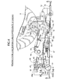
- a walking-type lawn mower 1 which is a power working machine, has a housing 3 supported by front wheels 2f and rear wheels 2r.
- a vertical engine 4 having a crankshaft 5 is mounted on an upper surface of the housing 3, with its crankshaft 5 vertically positioned.
- Rotary mowing blades 7 are provided in the housing 3 by being attached to the lower end of the crankshaft 5.
- a grass bag 8 is attached to an operating handle 6 connected to a rear end portion of the housing 3. Lawn grass clipped by the mowing blades 7 is collected in the glass bag 8.
- a flywheel 9 which functions as a cooling fan is fixed to the upper end of the crankshaft 5 of the engine 4; and an engine cover 10 which, along with the flywheel 9, covers an upper surface of the engine 4, and is fixed on the engine 4.
- a recoil-type starter 11 capable of driving the crankshaft 5 through the flywheel 9, and a starter cover 12 covering the starter 11 are mounted.
- a large number of cooling air intake openings 13 are provided in the starter cover 12 to draw cooling air into the engine cover 10 through the cooling air intake openings 13 during rotation of the flywheel 9, i.e., the cooling fan. Cooling air is led to each portion of the engine 4 by the engine cover 4.
- Reference symbol 11 a in FIG. 2 denotes a rope pulling grip of the starter 11.
- a brake shoe 16 which cooperates with a cylindrical peripheral surface of the flywheel 9 is mounted by means of a pivot 17 on a bracket 14 fixed on the engine 4 below the flywheel 9.
- the pivot 17 is placed at an inner position relative to the outer peripheral surface of the flywheel 9.
- the brake shoe 16 has an arm 16a extending between the bracket 14 and the flywheel 9 to an outer position relative to the peripheral surface of the flywheel 9, and a pressure contact portion 16b bent from the outer end of the arm 16a and facing the peripheral surface of the flywheel 9.
- a lining 18 is bonded to the pressure contact portion 16b.
- the brake shoe 16 can swingably move about the pivot 17 between a braking position A (see FIGS. 4 and 5) at which the lining 18 on the pressure contact portion 16b is pressed against the peripheral surface of the flywheel 9, and a brake release position B (see FIG. 6) at which the lining 18 is apart from the peripheral surface of the flywheel 9.
- a brake spring 19 which urges the brake shoe 16 toward the braking position A is connected to the front end of the pressure contact portion 16b of the brake shoe 16.
- the brake shoe 16, the flywheel 9 and the brake spring 19 constitute a braking mechanism 15 stopping the rotation of the crankshaft 5.
- An operating arm 16c is formed integrally with the brake shoe 16.
- An operating wire 21 operated by being pulled by a brake release lever 20 (see FIG. 1) axially supported on the operating handle 6 is connected to the operating arm 16c at the extreme end thereof.
- the brake shoe 16 can be turned to the brake release position B by means of the operating arm 16c.
- an engine kill switch 22 is provided on an upper surface of the bracket 14.
- the engine kill switch 22 makes an engine ignition circuit (not shown) nonoperative in interlock with a turn of the brake shoe 16 to the braking position A to stop the operation of the engine 4.
- a carburetor 23 is mounted on the engine 4 on the left or right side of the engine 4, while an exhaust muffler 26 is mounted on the engine 4 on the right or left side.
- An air cleaner 24 is connected to an upstream end of the carburetor 23.
- the carburetor 23 includes a carburetor body 30 having an intake path 30a, a butterfly-type choke valve 31 for opening and closing an upstream portion of the intake path 30a, and a butterfly-type throttle valve 32 for opening and closing the intake path 30a on the downstream side.
- Valve shafts 31a and 32a of the choke valve 31 and the throttle valve 32 are rotatably supported on the carburetor body 30 while being vertically positioned, as is the crankshaft 5 of the engine 4.
- the valve shaft 31a of the choke valve 31 is offset from a center line of the intake path 30a on one side thereof, and is tilted from the center line of the intake path 30a so that, in its completely closed state, its larger-radius portion is placed downstream relative to its smaller-radius portion in the intake path 30a.
- a choke lever 33 is attached to an outer end portion of the valve shaft 31a projecting outside the carburetor body 30.
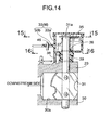
- the choke lever 33 has a hub 33a which is a bottomed cylindrical member rotatably fitted around the valve shaft 31a, and a lever arm 33b formed integrally with the hub 33a so as to project from one side surface of the hub 33a.
- a pair of stopper projections 34 and 34' are formed inside the hub 33a in a state of being spaced apart from each other through a certain distance along the circumferential direction of the hub 33a.
- a relief lever 35 turnable only between the stopper projections 34 and 34' is fixed to the valve shaft 31a, and a relief spring 36 which urges the relief lever 35 so that the relief lever 34 is brought into contact with the stopper 34 positioned on the closing side of the choke valve 31 is provided between the hub 33a and the relief lever 35.
- a pair of stopper walls 37 and 37' are formed on an outer circumferential surface of a lower part of the hub 33a in a state of being spaced apart from each other through a certain distance along the circumferential direction of the hub 33a.
- a stopper pin 38 is formed on an outer surface of the carburetor body 30 so as to project therefrom to be placed between the stopper walls 37 and 37'.
- the closing position C of the choke lever 33 at which the choke valve 31 is completely closed is determined by the contact of one stopper wall 37 with the stopper pin 38, and the opening position O of the choke lever 33 at which the choke valve 31 is fully opened is determined by the contact of the other stopper wall 37' with the stopper pin 38.
- the negative suction pressure of the engine exceeds a certain value when the degree of opening of the choke valve 31 is zero or small, the difference between the moment of rotation due to the negative suction pressure acting on the larger-radius portion of the choke valve 31 and the moment of rotation due to the negative function pressure acting on the smaller-radius portion of the choke valve 31 prevails the moment of rotation caused by the relief spring 36, to thereby increase the degree of opening of the choke valve 31.
- the increase in the degree of opening is limited by the contact of the relief lever 35 with the other stopper projection 34'.
- a throttle lever 40 is fixed to an outer end portion of the valve shaft 32a of the throttle valve 32 projecting outside the carburetor body 30, and a long arm portion 42a of a governor lever 42 fixed to an outer end portion of a rotary support shaft supported on the engine 4 is connected to the throttle lever 40 by a link 43.
- a governor spring 44 which urges the governor lever 42 in the throttle valve 32 opening direction by a certain load is also connected to the governor lever 42.
- an output shaft 45a of a known centrifugal governor 45 driven by the crankshaft 5 of the engine 4 is linked to a short arm portion 42b of the governor lever 42.
- the output from the centrifugal governor 45 which increases with the increase in the rotational speed of the engine 4 acts on the short arm portion 42b in the throttle valve 32 closing direction through the output shaft 45a.
- the throttle lever 40 is held at the throttle valve 32 closing position C by the set load of the governor spring 44.
- the degree of opening of the throttle valve 32 is automatically controlled by balancing between the moment of the governor lever 42 due to the output from the centrifugal governor 45 and the moment of the governor lever 42 due to the load of the governor spring 44.
- a choke valve control device 27 which automatically opens and closes the choke valve 31, will now be described.
- a supporting plate 25 combined with the bracket 14 and extending vertically is interposed between the carburetor 23 and the air cleaner 24.
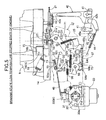
- first to third control levers 51 to 53 are rotatably mounted by first to third pivots 54 to 56.
- the second control lever 52 is placed between the first control lever 51 and the carburetor 23, and the third control lever 53 is placed immediately below the second control lever 52.
- the first control lever 51 has an end extending toward the second control lever 52, and a claw portion 51a which is formed on its base portion and which disengages from a front edge of the release arm 16c when the brake shoe 16 is in the braking position A.
- a first return spring 57 which urges the claw portion 51a in the direction for engagement with the release arm 16c is connected to the first control lever 51.
- the first control lever 51 turns between a first position D at which the claw portion 51 a contacts the front end of the release arm 16c at the braking position A, and a second position E at which the release arm 16c presses the claw portion 51 a after being turned to the brake release position B.
- the second control lever 52 has upper and lower arm portions 52a and 52b extending upward and downward, respectively, from the second pivot 55, and an elastic arm portion 52c extending toward the first control lever 51 and having flexibility.
- a circular-arc elongated hole 59 concentric with the second pivot 55 is provided in the upper arm portion 52a.
- One end of a link 46 having the other end slidably fitted in the elongated hole 59 is connected to an end portion of the lever arm 33b of the choke lever 33.
- the elastic arm portion 52c is pushed by the first control lever 51 when the first control lever 51 turns from the first position D to the second position E. By this pushing, the second control lever 52 turns the choke lever 33 to the closing position C through the link 46.
- a contact wall 60 is formed on the lower arm portion 52b of the second control lever 52 to rise along the axial direction of the second pivot 55.
- a second return spring 58 which urges the second control lever 52 in such a direction that the contact wall 60 is brought into contact with an upper arm portion 53a of the third control lever 53 described below, is stretched between a second control spring 67 and the supporting plate 25.
- the throttle lever 40 has a lock arm 49 having elasticity for bending in the axial direction of the valve shaft 32a.
- a locked arm 50 provided in correspondence with the lock arm 49 is integrally formed on the choke lever 33.
- the locked arm 50 is held by the lock arm 49 when the choke lever 33 is turned to the closing position C in the state where the throttle valve 32 is fully opened. That is, as shown in FIGS. 17A to 17C, the lock arm 49 enters the turning path for the locked arm 50 when the throttle lever 40 is in the full-open position.
- a sloping surface 61 is formed in the lock arm 49 at one side in the turning direction so that the sloping surface 61 is pressed and lifted by the locked arm 50 when the locked arm 50 turns the choke lever 33 to the closing position C.
- a contact surface 62 which receives the locked arm 50 to hold the choke lever 33 in the closing position C immediately after the locked arm 50 has passed below the lock arm 49 is formed at the other side.
- the third control lever 53 has upper and lower arm portions 53a and 53b extending upward and downward, respectively, from the third pivot 56. An extreme end of the upper arm portion 53a is brought into contact with the contact wall 60 of the lower arm portion 52b of the second control lever 52 from the carburetor 23 side.
- the position of the third control lever 53 when the lower arm portion 53b is brought into contact with the first stopper wall 64a on the carburetor 23 side will be referred to as a low-temperature position L
- the position of the third control lever 53 when the lower arm portion 53b is brought into contact with the second stopper wall 64b opposite from the carburetor 23 will be referred to as a high-temperature position H.
- a spring engagement member 65 juxtaposed with the third control lever 53 on the side opposite from the carburetor 23 is fixed on the supporting plate 25.
- the spring engagement member 65 also has upper and lower arm portions 65a and 65b corresponding to the upper and lower arm portions 53a and 53b of the third control lever 53.
- Opposite ends of a first control spring 66 formed of a tensile coil spring are connected to the upper arm portions 52a and 65a, while opposite ends of the second control spring 67 formed of a tensile coil spring are connected to the lower arm portions 52b and 65b.
- the set load of the first control spring 66 is set higher than that of the second return spring 58.
- the second control spring 67 is made of a shape memory alloy.
- the second control spring 67 loses its spring function at a temperature lower than a shape restoration temperature corresponding to the ambient temperature at the end of warm-up operation of the engine 4, but exerts a set load (tensile force) higher than that of the first control spring 66 at a temperature equal to or higher than the shape restoration temperature.
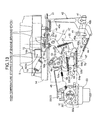
- the brake release lever 20, the operating wire 21 and the release arm 16c constitute brake release means 70 for releasing the brake shoe 16 from the state of braking the flywheel 9;
- the first and second control levers 51 and 52 and the link 46 constitute automatic choke closing means 71 for turning the choke lever 33 to the closing position C in interlock with the operation of the brake release means 70;
- the lock arm 49 and the locked arm 50 constitute choke valve closed state hold means 72 for holding the choke lever 33 in the closing position C;
- the link 46 and the elongated hole 59 constitute lost motion means 73 for allowing a return of the second control lever 52 caused by the second return spring after the choke lever 33 has been held in the closing position C;
- the second return spring 58, the third control lever 53, the first stopper wall 64a and the first control spring 66 constitute warm-up control means 74 for holding the choke lever 33 in a state of half opening the choke valve 31;
- the third control lever 53, the second stopper wall 64b and the second control spring 67 constitute automatic choke opening means 75 for turning the
- the first control lever 51 is held in the first position D, with the claw portion 51a maintained in engagement with the front edge of the release arm 16c by the urging force of the first return spring 57.
- the second control lever 52 has the contact wall 60 of the lower arm portion 52b brought into contact with the extreme end of the upper arm portion 53a of the third control lever 53 by the urging force of the second return spring 58.
- the ambient temperature is lower than the shape restoration temperature of the second control spring 67, so that the second control spring 67 loses the spring function.
- the third control lever 53 is held in the low-temperature position L, with its lower arm portion 53b maintained in contact with the first stopper wall 64a by the urging force of the first control spring 66, and with its upper arm portion 53a receiving the lower arm portion 52b of the second control lever 52 at the position remotest from the carburetor 23.
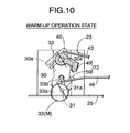
- the choke lever 33 is urged by the urging force of the choke spring 39 to turn in the choke valve 31 opening direction, but the choke valve 31 is held in a half opened state by the contact of the link 46 with one inner end wall of the elongated hole 59 of the upper arm portion 52a of the second control lever 52.
- the operating wire 21 is first pulled by gripping the brake release lever 20 together with the operating handle 6 to operate the release arm 16c.
- the brake shoe 16 is thereby turned to the brake release position B to release the force for braking the flywheel 9.
- the crankshaft 5 is thereby made free.
- engine kill switch 22 is made nonoperative by the brake shoe 16 (the ignition circuit is made operative).
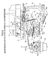
- the release arm 16c of the brake shoe 16 simultaneously turns clockwise the claw portion 51a, i.e., the first control lever 51, as shown in FIG. 6.
- the first control lever 51 thereby turns counterclockwise the elastic arm portion 52c, i.e., the second control lever 52.
- the second control lever 52 presses the link 46 to turn the choke lever 33 to the closing position C, as shown in FIG. 7.
- the locked arm 50 formed integrally with the choke lever 33 slides on the sloping surface 61 of the lock arm 49 of the throttle lever 40 and wedges away the lock arm 49 to cause the same to temporarily bend upward (see FIG. 17B), to pass below the lock arm 49.
- the lock arm 49 returns to the original state and the contact surface 62 is brought into contact with the locked arm 50 (see FIG. 17C), thereby holding the choke lever 33 in the closing position C.
- the first control lever 51 passes the elastic arm portion 52c of the second control lever 52 by causing the elastic arm portion 52c to bend, i.e., releasing the elastic arm portion 52c, to reach the second position E.
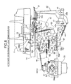
- the second control lever 52 thus released from the first control lever 51 is returned to the original position by the urging force of the second return spring 58 (see FIG. 8).
- the elongated hole 59 of the second control lever 52 moves relative to the link 46 connected to the choke lever 33. Therefore, the second control lever 52 can return to the original position without interference with the link 46, while leaving the choke lever 33 in the closing position C.
- the choke lever 33 can be automatically held in the closing position C by being interlocked with the operation of the brake release lever 20. Therefore, it is not necessary for the operator to touch the choke lever 33 when starting the engine 4, and the operator is free from anxiety about forgetting closing the choke valve 31.
- the recoil starter 11 is operated to crank the engine 4.
- the choke valve 31 is already in the completely closed state in the intake path 30a of the carburetor 23, and a fuel-rich air- fuel mixture suitable for a cold start is therefore generated.
- the engine 4 into which this air-fuel mixture is drawn can start rapidly.
- the centrifugal governor 45 produces the output corresponding to the rotational speed of the crankshaft 5 when the engine 4 is started, and the governor lever 42 turns to a position at which the moment of the governor lever 42 due to this output and the moment of the governor lever 42 due to the load of the governor spring 44 balance with each other, thereby automatically closing the throttle valve 32.
- the locked arm 50 of the choke lever 33 is thereby released from the state of being locked by the lock arm 49 of the throttle lever 40.
- the choke lever 33 is turned by the urging force of the choke spring 39 so as to open the choke valve 31.
- the rightward movement of the link 46 with this turning as viewed in FIG.
- crankshaft 5 drives and rotates the mowing blades 7 and the operator can perform a mowing operation by forcing forward the power lawn mower 1 while gripping the operating handle 6 and the brake release lever 20.
- the ambient temperature also increases to heat the second control spring 67 at a temperature equal to or higher than the shape restoration temperature.
- the second control spring 67 then performs its proper spring function to generate a set load (tensile force) higher than that of the first control spring 66 and thereby turns counterclockwise the third control lever 53 to the high-temperature position H at which the lower arm portion 53b is brought into contact with the second stopper wall 64b against the set load of the first control spring 66, as shown in FIG. 11.
- the upper arm portion 53a of the third control lever 53 is thereby moved back from the contact wall 60 of the lower arm portion 52b of the second control lever 52.
- the second control lever 52 is then turned by the urging force of the second return spring 58 so as to follow the backward movement of the upper arm portion 53a to free the end of the link 46 in the elongated hole 59. Consequently, the choke lever 33 is turned to the opening position O by the urging force of the choke spring 39, thus automatically setting the choke valve 31 in the full open state to adjust the concentration of fuel in the air-fuel mixture generated in the carburetor 23 to the normal value. Since the shape restoration of the second control spring 67 is effected comparatively gradually with the increase in the engine ambient temperature, the transition of the choke valve 31 to the full open state is also effected gradually. Therefore, the concentration of fuel in the air -fuel mixture changes gradually. Thus, occurrence of an engine operation disorder due to an abrupt change in the concentration of fuel in the air-fuel mixture can be prevented.
- the second control spring 67 made of a shape memory alloy is made to perform its proper spring function at the end of warm -up operation of the engine 4, to perform control for automatically setting the choke valve 31 in the full open state by using the third control lever 53 turned to the high -temperature position H.
- the opening of the choke valve 31 is controlled in a rational way according to the increase in engine temperature, thus satisfying both stabilization of engine warm-up operation and improvement of the fuel consumption rate.
- This choke valve control device 27 is mechanically constituted by the first to third control levers, the first and second control springs 66 and 67, and other parts, and is comparatively simple in construction. Therefore this choke valve control device 27 can be provided at a reduced cost. Moreover, the control of the choke valve can be stabilized without being influenced by pulsation of the negative suction pressure in the engine.
- the brake shoe 16 When the operator looses his/her hold on the brake release lever 20 continuously pulled by the operator, the brake shoe 16 operates the engine kill switch 22 while being returned to the braking position A in which it is pressed against the flywheel 9 by the urging force of the brake spring 19. The engine 4 is thereby held immediately in the operation stopped state. At this time, the release arm 16c of the brake shoe 16 releases the claw portion 51a of the first control lever 51, and the second control lever 52 turns the claw portion 51a to the original position in which the claw portion 51a is engaged with the front end of the release arm 16c of the brake shoe 16 by the urging force of the first return spring 57.
- the second control lever 52 is held by the third control lever 53 in the high-temperature position H, and has the elastic arm portion 52c positioned out of the turning path for the first control lever 51, it can return to the original position without contacting the elastic arm portion 52c.
- the second control lever 52 is positioned by the third control lever 53 in the high-temperature position H to maintain the choke lever 33 in the released position, i.e., the open position O. Therefore, in this state, if the recoil starter 11 is operated to crank the engine 4, a comparatively lean air-fuel mixture suitable for a hot start is generated in the intake path 30a of the carburetor 23, thus appropriately performing a hot start of the engine 4.
- the spring 67 looses the spring function and, therefore, the third control lever 53 enters the state under the control with the first control spring 66 to be turned to the low-temperature position L. Then, with this turning, the upper arm portion 53 a of the third control lever 53 returns the second control lever 52 to the original position against the urging force of the second return spring 58. With this operation, the choke lever 33 can return to the original position corresponding to the half opened state of the choke valve 31 as shown in FIGS. 4 and 5.
- FIGS. 18A to 18C A second embodiment of the present invention shown in FIGS. 18A to 18C will be described.
- the second embodiment uses, in the choke valve closed state hold means 72, expansion/contraction of the relief spring 36 (see FIG. 14) in the hub 33a of the choke lever 33 for the vertical movement of the locked arm 50. That is, while each of the lock arm 49 and the locked arm 50 is given rigidity, a sloping surface 61 having a gradient reverse to that in the first embodiment is formed as one side surface of the locked arm 50 formed integrally with the hub 33a. In other respects, the construction is the same as that of the first embodiment. Since the other components are the same as those in the first embodiment, portions corresponding to those in the first embodiment are indicated by the same reference numerals in FIGS. 18A to 18C.
- each choke valve closed state hold means 72 has the lock arm 49 provided continuously with the throttle lever 40 and the locked arm 50 provided continuously with the choke lever 33, the lock arm 49 and the locked arm 50 elastically surmounting each other when the choke lever 33 is turned to the closing position C in the state where the throttle lever 40 is in the opening position corresponding to the full open position of the throttle valve 32, so that the lock arm 49 prevents the locked arm 50 from turning back.
- the choke valve closed state hold means 72 is simple in construction and can contribute to a reduction in the manufacturing cost of the choke valve control device 27.
Landscapes
- Engineering & Computer Science (AREA)
- Chemical & Material Sciences (AREA)
- Combustion & Propulsion (AREA)
- Mechanical Engineering (AREA)
- General Engineering & Computer Science (AREA)
- Means For Warming Up And Starting Carburetors (AREA)
- Control Of Throttle Valves Provided In The Intake System Or In The Exhaust System (AREA)
Abstract
Description
Claims (6)
- A device for controlling a choke valve of a carburetor annexed to an engine, comprising:choke closed state hold means for holding a choke lever in a closing position corresponding to the completely closed position of the choke valve, the choke lever being connected to the choke valve and when turned to the closing position being urged by a spring in a direction for opening the choke valve, the choke closed state hold means releasing the choke lever from the held state by a throttle operation thereafter performed on the carburetor;a control lever which turns between a low-temperature position and a high-temperature position while being axially supported on a fixed structural member, and which at its low-temperature position limits the position of the choke lever released from the choke closed state hold means to an intermediate position corresponding to a half opened position of the choke valve and at its high-temperature position limits the position of the choke lever to an opening position corresponding to a full open position of the choke;a first control spring which urges the control lever toward the low-temperature position; anda second control spring which is made of a shape memory alloy, and which under the influence of the engine temperature enters a shape restored state when the engine temperature reaches a predetermined high temperature to exert a spring force for turning the control lever to the high-temperature position against the urging force of the first control spring.
- The device according to claim 1, wherein the choke closed state hold means includes a lock arm provided continuously with a throttle lever connected to a throttle valve of the carburetor and a locked arm provided continuously with the choke lever, when the choke lever is turned to the closing position in a state where the throttle lever is in the opening position corresponding to the full open position of the throttle valve, the lock arm preventing the locked arm from turning back; a governor spring which urges the throttle lever in a direction for opening the throttle valve and a governor which produces an output for urging the throttle lever in a direction for closing the throttle valve according to an increase in the rotational speed of the engine are connected to the throttle lever; and the lock arm releases the locked arm by turning of the throttle lever in the direction for closing the throttle lever by the output from the governor.
- The device according to claim 1 or 2, further comprising:a braking mechanism for stopping the rotation of an output shaft of the engine;brake release means manually operated so as to release the braking mechanism from the operating state;a choke spring which urges the choke valve in the direction for opening the valve, and which is connected to the choke valve;automatic choke valve opening means for automatically opening, in cooperation with the choke spring, after a start of the engine, the choke valve held in the closed position immediately before the start of the engine, the automatic choke valve opening means being also connected to the choke valve; andautomatic choke valve closing means for turning the choke valve to the closed position in interlock with the operation of the brake release means, the automatic choke valve closing means being provided between the choke valve and the brake release means.
- The device according to claim 3, wherein the automatic choke closing means includes a first control lever which is axially supported on a fixed structural member of the engine, and which turns to a first position and a second position by being interlocked with nonoperative and operative states of the brake release means, and a second control lever which is axially supported on the fixed structural member, and which, when the first control lever turns to the second position, is thereby driven to turn the choke lever connected to the choke valve to the position for closing the choke valve and is thereafter released from the first control lever, the device further comprising a return spring which urges the second control lever in a direction for opening the choke valve, and which is connected to the second control lever, and lost motion means for leaving the choke lever in the closing position when the second control lever is returned by the return spring, the lost motion means being provided between the second control lever and the choke lever.
- The device according to claim 1, further comprising:a first control lever which is axially supported on a fixed structural member, and which is manually turned between a first position and a second position;a second control lever which is axially supported on the fixed structural member, and which, when the first control lever turns to the second position, is thereby driven to turn the choke lever connected to the choke valve to the closing position corresponding to the completely closed position of the choke valve and is thereafter released from the first control lever;choke closed state hold means for holding the choke lever in the closing position when the choke lever is turned to the closing position, the choke closed state hold means releasing the choke lever from the held state after the start of the engine;a third control lever which turns between a low-temperature position and a high-temperature position while being axially supported on the fixed structural member, and which at its low-temperature position limits the position of the choke lever released from the choke closed state hold means to an intermediate position corresponding to a half opened position of the choke valve and at its high-temperature position limits the position of the choke lever to an opening position corresponding to a full open position of the choke valve;a first control spring which urges the control lever toward the low-temperature position; anda second control spring which is made of a shape memory alloy, and which under the influence of the engine temperature enters a shape restored state when the engine temperature reaches a predetermined high temperature to exert a spring force for turning the control lever to the high-temperature position against the urging force of the first control spring.
- The device according to claim 5, wherein the choke closed state hold means is released from the operating state by a throttle operation performed on the carburetor after the start of the engine.
Applications Claiming Priority (12)
| Application Number | Priority Date | Filing Date | Title |
|---|---|---|---|
| JP2004058759 | 2004-03-03 | ||
| JP2004058759 | 2004-03-03 | ||
| JP2004058761 | 2004-03-03 | ||
| JP2004058761 | 2004-03-03 | ||
| JP2004058760 | 2004-03-03 | ||
| JP2004058760 | 2004-03-03 | ||
| JP2004116910A JP4129244B2 (en) | 2004-03-03 | 2004-04-12 | Vaporizer choke valve control device |
| JP2004116911A JP4129245B2 (en) | 2004-03-03 | 2004-04-12 | Vaporizer choke valve control device |
| JP2004116910 | 2004-04-12 | ||
| JP2004116911 | 2004-04-12 | ||
| JP2004116909 | 2004-04-12 | ||
| JP2004116909A JP4129243B2 (en) | 2004-03-03 | 2004-04-12 | Choke valve control device for carburetor in power working machine |
Publications (3)
| Publication Number | Publication Date |
|---|---|
| EP1571310A2 true EP1571310A2 (en) | 2005-09-07 |
| EP1571310A3 EP1571310A3 (en) | 2008-11-19 |
| EP1571310B1 EP1571310B1 (en) | 2011-09-28 |
Family
ID=34754008
Family Applications (1)
| Application Number | Title | Priority Date | Filing Date |
|---|---|---|---|
| EP05251273A Expired - Lifetime EP1571310B1 (en) | 2004-03-03 | 2005-03-03 | Device for controlling choke valve of carburetor |
Country Status (7)
| Country | Link |
|---|---|
| US (1) | US7118097B2 (en) |
| EP (1) | EP1571310B1 (en) |
| KR (1) | KR100683015B1 (en) |
| CN (1) | CN100360777C (en) |
| AU (1) | AU2005200859B2 (en) |
| CA (1) | CA2499156C (en) |
| TW (1) | TWI268309B (en) |
Cited By (1)
| Publication number | Priority date | Publication date | Assignee | Title |
|---|---|---|---|---|
| EP2679358A3 (en) * | 2012-06-28 | 2014-12-17 | Andreas Stihl AG & Co. KG | Power tool having a braking system |
Families Citing this family (25)
| Publication number | Priority date | Publication date | Assignee | Title |
|---|---|---|---|---|
| TWI268309B (en) * | 2004-03-03 | 2006-12-11 | Honda Motor Co Ltd | Device for controlling choke valve of carburetor |
| TWI297372B (en) * | 2004-03-03 | 2008-06-01 | Honda Motor Co Ltd | Device for controlling choke valve of carburetor |
| ES2307095T3 (en) * | 2004-08-18 | 2008-11-16 | Honda Motor Co., Ltd. | CARBURETOR ELECTRONIC CONTROL SYSTEM. |
| JP4464849B2 (en) * | 2005-03-07 | 2010-05-19 | 本田技研工業株式会社 | Ventilator throttle valve control device |
| JP4523543B2 (en) * | 2005-12-14 | 2010-08-11 | 本田技研工業株式会社 | Engine carburetor automatic control device |
| US8341958B2 (en) * | 2006-07-25 | 2013-01-01 | Brown James Holbrook | Shape memory alloy actuated device |
| JP4732378B2 (en) * | 2007-02-12 | 2011-07-27 | 本田技研工業株式会社 | Engine control device |
| US8434444B2 (en) * | 2008-05-27 | 2013-05-07 | Briggs & Stratton Corporation | Engine with an automatic choke and method of operating an automatic choke for an engine |
| CN101713352B (en) * | 2008-09-30 | 2016-02-17 | 布里格斯斯特拉顿公司 | Engine vaporizer and automatic choke assembly |
| US8459137B1 (en) * | 2010-04-07 | 2013-06-11 | Hydro-Gear Limited Partnership | Control assembly for drive system |
| CN101922381B (en) * | 2010-07-23 | 2012-07-04 | 陈俭敏 | Carburetor and choke valve control mechanism thereof |
| DE102010048773A1 (en) * | 2010-10-16 | 2012-04-19 | Andreas Stihl Ag & Co. Kg | carburettor |
| JP5846852B2 (en) * | 2011-10-26 | 2016-01-20 | 株式会社ミクニ | Vaporizer choke mechanism |
| DE102012012827A1 (en) | 2012-06-28 | 2014-01-02 | Andreas Stihl Ag & Co. Kg | Start safety circuit in a working device with an internal combustion engine |
| DE102012012798B4 (en) | 2012-06-28 | 2014-11-13 | Andreas Stihl Ag & Co. Kg | Working device with a braking device |
| DE102012012801A1 (en) | 2012-06-28 | 2014-01-02 | Andreas Stihl Ag & Co. Kg | implement |
| US9261030B2 (en) | 2013-05-20 | 2016-02-16 | Kohler Co. | Automatic fuel shutoff |
| US9464588B2 (en) | 2013-08-15 | 2016-10-11 | Kohler Co. | Systems and methods for electronically controlling fuel-to-air ratio for an internal combustion engine |
| JP6260140B2 (en) * | 2013-08-19 | 2018-01-17 | 日立工機株式会社 | Engine working machine |
| US9074535B1 (en) | 2013-12-19 | 2015-07-07 | Kohler Co. | Integrated engine control apparatus and method of operating same |
| US10054081B2 (en) | 2014-10-17 | 2018-08-21 | Kohler Co. | Automatic starting system |
| US11111861B2 (en) * | 2017-03-03 | 2021-09-07 | Briggs & Stratton, Llc | Engine speed control system |
| SE541417C2 (en) * | 2017-06-12 | 2019-09-24 | Husqvarna Ab | A carburetor assembly start setting detection arrangement |
| CN108313308A (en) * | 2018-03-14 | 2018-07-24 | 长沙市云智航科技有限公司 | A kind of rotor for manned more rotor flying vehicles |
| JP7487091B2 (en) * | 2020-12-21 | 2024-05-20 | 株式会社Willbe | Hunting detection device and hunting detection method |
Citations (5)
| Publication number | Priority date | Publication date | Assignee | Title |
|---|---|---|---|---|
| US3886917A (en) | 1972-07-13 | 1975-06-03 | Toyota Motor Co Ltd | Carburetor with automatic choke |
| DE2928092A1 (en) | 1979-07-12 | 1981-01-22 | Pierburg Gmbh & Co Kg | CARBURETOR WITH COLD START |
| JPS6324354U (en) | 1986-08-01 | 1988-02-17 | ||
| US5069180A (en) | 1990-10-19 | 1991-12-03 | Onan Corporation | Automatic choke apparatus and method |
| EP1323916A2 (en) | 2001-12-27 | 2003-07-02 | Honda Giken Kogyo Kabushiki Kaisha | Control system for choke valve of carburetor |
Family Cites Families (23)
| Publication number | Priority date | Publication date | Assignee | Title |
|---|---|---|---|---|
| US2410758A (en) * | 1941-07-20 | 1946-11-05 | Bendix Aviat Corp | Carburetor |
| US2998233A (en) * | 1959-11-18 | 1961-08-29 | Holley Carburetor Co | Automatic choke |
| US3284061A (en) * | 1964-03-02 | 1966-11-08 | Acf Ind Inc | Carburetor |
| US3321193A (en) * | 1964-03-26 | 1967-05-23 | Acf Ind Inc | Carburetor |
| US3789814A (en) * | 1972-09-14 | 1974-02-05 | Gen Motors Corp | Ambient temperature regulated choke |
| JPS517338A (en) * | 1974-07-05 | 1976-01-21 | Honda Motor Co Ltd | Kikakino chookubenseigyosochi |
| US3935290A (en) | 1974-08-05 | 1976-01-27 | Ford Motor Company | Carburetor cold engine fuel enrichment system |
| JPS5620723A (en) * | 1979-07-30 | 1981-02-26 | Kubota Ltd | Mechanical governor for gasoline engine |
| US4297980A (en) * | 1980-04-10 | 1981-11-03 | Ford Motor Company | Motor vehicle carburetor choke mechanism |
| US4331615A (en) * | 1980-11-06 | 1982-05-25 | Texas Instruments Incorporated | Fuel supply system with automatic choke |
| US4463723A (en) * | 1982-04-01 | 1984-08-07 | Acf Industries, Incorporated | Apparatus for controllably opening a carburetor choke valve |
| US4465640A (en) * | 1982-06-09 | 1984-08-14 | Colt Industries Operating Corp | Adjustable choke linkage means |
| JPS6030459A (en) * | 1983-07-30 | 1985-02-16 | Fuji Heavy Ind Ltd | Choke valve system for carburetor |
| JPS6324354A (en) | 1986-03-10 | 1988-02-01 | Nippon Denki Off Syst Kk | Document preparing device |
| JPS62267549A (en) | 1986-05-15 | 1987-11-20 | Mitsubishi Heavy Ind Ltd | Auto choke device for internal combustion engine |
| JPH06147012A (en) * | 1991-04-08 | 1994-05-27 | Mikuni Corp | Vaporizer |
| SE510116C2 (en) * | 1995-06-09 | 1999-04-19 | Electrolux Ab | Compensating damper |
| US5660765A (en) * | 1996-06-26 | 1997-08-26 | Kohler Co. | Thermostatic element for controlling a solenoid operated carburetor choke |
| JP2001065407A (en) | 1999-08-30 | 2001-03-16 | Kyoritsu Seisakusho:Kk | Engine auto choke device |
| US6990969B2 (en) * | 2003-07-30 | 2006-01-31 | Briggs And Stratton Corporation | Automatic choke for an engine |
| TWI268309B (en) * | 2004-03-03 | 2006-12-11 | Honda Motor Co Ltd | Device for controlling choke valve of carburetor |
| TWI297372B (en) * | 2004-03-03 | 2008-06-01 | Honda Motor Co Ltd | Device for controlling choke valve of carburetor |
| JP4129243B2 (en) | 2004-03-03 | 2008-08-06 | 本田技研工業株式会社 | Choke valve control device for carburetor in power working machine |
-
2005
- 2005-02-22 TW TW094105245A patent/TWI268309B/en not_active IP Right Cessation
- 2005-02-25 AU AU2005200859A patent/AU2005200859B2/en not_active Ceased
- 2005-03-02 CA CA002499156A patent/CA2499156C/en not_active Expired - Fee Related
- 2005-03-02 US US11/069,065 patent/US7118097B2/en not_active Expired - Lifetime
- 2005-03-03 KR KR1020050017652A patent/KR100683015B1/en not_active Expired - Fee Related
- 2005-03-03 CN CNB2005100512960A patent/CN100360777C/en not_active Expired - Fee Related
- 2005-03-03 EP EP05251273A patent/EP1571310B1/en not_active Expired - Lifetime
Patent Citations (5)
| Publication number | Priority date | Publication date | Assignee | Title |
|---|---|---|---|---|
| US3886917A (en) | 1972-07-13 | 1975-06-03 | Toyota Motor Co Ltd | Carburetor with automatic choke |
| DE2928092A1 (en) | 1979-07-12 | 1981-01-22 | Pierburg Gmbh & Co Kg | CARBURETOR WITH COLD START |
| JPS6324354U (en) | 1986-08-01 | 1988-02-17 | ||
| US5069180A (en) | 1990-10-19 | 1991-12-03 | Onan Corporation | Automatic choke apparatus and method |
| EP1323916A2 (en) | 2001-12-27 | 2003-07-02 | Honda Giken Kogyo Kabushiki Kaisha | Control system for choke valve of carburetor |
Cited By (2)
| Publication number | Priority date | Publication date | Assignee | Title |
|---|---|---|---|---|
| EP2679358A3 (en) * | 2012-06-28 | 2014-12-17 | Andreas Stihl AG & Co. KG | Power tool having a braking system |
| RU2629107C2 (en) * | 2012-06-28 | 2017-08-24 | Андреас Штиль АГ унд Ко. КГ | Operating tool with braking unit |
Also Published As
| Publication number | Publication date |
|---|---|
| KR100683015B1 (en) | 2007-02-15 |
| KR20060043373A (en) | 2006-05-15 |
| AU2005200859B2 (en) | 2008-01-10 |
| CA2499156A1 (en) | 2005-09-03 |
| CN1683773A (en) | 2005-10-19 |
| CN100360777C (en) | 2008-01-09 |
| US7118097B2 (en) | 2006-10-10 |
| US20050194700A1 (en) | 2005-09-08 |
| EP1571310B1 (en) | 2011-09-28 |
| TWI268309B (en) | 2006-12-11 |
| CA2499156C (en) | 2008-05-20 |
| EP1571310A3 (en) | 2008-11-19 |
| TW200533832A (en) | 2005-10-16 |
| AU2005200859A1 (en) | 2005-09-22 |
Similar Documents
| Publication | Publication Date | Title |
|---|---|---|
| CA2499156C (en) | Device for controlling choke valve of carburetor | |
| CA2499157C (en) | Device for controlling choke valve of carburetor | |
| JP4177004B2 (en) | Carburetor throttle and choke control mechanism | |
| GB2168434A (en) | Automatic choke control for starting an i c engine | |
| EP1630400A2 (en) | Automatic choke for an engine | |
| JP4129243B2 (en) | Choke valve control device for carburetor in power working machine | |
| JP4129245B2 (en) | Vaporizer choke valve control device | |
| EP1640592B1 (en) | Combustion engine pull-cord start system | |
| US4114584A (en) | Carburetor choke positive closure mechanism | |
| US3965224A (en) | Carburetor choke valve positioner | |
| JP4243213B2 (en) | Vaporizer choke valve control device | |
| JP4129244B2 (en) | Vaporizer choke valve control device | |
| US4196156A (en) | Carburetor with limited interconnected choke valve and fast idle cam | |
| US4129623A (en) | Carburetor with fast idle cam automatic release | |
| US3862278A (en) | Control mechanism for carburetor automatic choke | |
| CN2908824Y (en) | Carburetor choke control | |
| JP3828803B2 (en) | Choke valve control device for carburetor in power working machine | |
| JP3901516B2 (en) | Vaporizer choke valve control device | |
| CA1126112A (en) | Two stage choke valve pulldown and fast idle cam pulloff device | |
| CA1137841A (en) | Carburetor | |
| ES2370318T3 (en) | DEVICE FOR CONTROLLING A CARBURETOR CHANNEL VALVE. |
Legal Events
| Date | Code | Title | Description |
|---|---|---|---|
| PUAI | Public reference made under article 153(3) epc to a published international application that has entered the european phase |
Free format text: ORIGINAL CODE: 0009012 |
|
| AK | Designated contracting states |
Kind code of ref document: A2 Designated state(s): AT BE BG CH CY CZ DE DK EE ES FI FR GB GR HU IE IS IT LI LT LU MC NL PL PT RO SE SI SK TR |
|
| AX | Request for extension of the european patent |
Extension state: AL BA HR LV MK YU |
|
| PUAL | Search report despatched |
Free format text: ORIGINAL CODE: 0009013 |
|
| AK | Designated contracting states |
Kind code of ref document: A3 Designated state(s): AT BE BG CH CY CZ DE DK EE ES FI FR GB GR HU IE IS IT LI LT LU MC NL PL PT RO SE SI SK TR |
|
| AX | Request for extension of the european patent |
Extension state: AL BA HR LV MK YU |
|
| RIC1 | Information provided on ipc code assigned before grant |
Ipc: F02M 1/10 20060101AFI20081010BHEP |
|
| 17P | Request for examination filed |
Effective date: 20081120 |
|
| 17Q | First examination report despatched |
Effective date: 20090126 |
|
| AKX | Designation fees paid |
Designated state(s): BE DE ES FR GB IT |
|
| GRAP | Despatch of communication of intention to grant a patent |
Free format text: ORIGINAL CODE: EPIDOSNIGR1 |
|
| GRAS | Grant fee paid |
Free format text: ORIGINAL CODE: EPIDOSNIGR3 |
|
| GRAA | (expected) grant |
Free format text: ORIGINAL CODE: 0009210 |
|
| RIN1 | Information on inventor provided before grant (corrected) |
Inventor name: ARAI, TETSUYA Inventor name: SATO, TAKANORI Inventor name: MORIYAMA, HIROSHI Inventor name: SUZUKI, TAKASHI |
|
| AK | Designated contracting states |
Kind code of ref document: B1 Designated state(s): BE DE ES FR GB IT |
|
| REG | Reference to a national code |
Ref country code: GB Ref legal event code: FG4D |
|
| REG | Reference to a national code |
Ref country code: DE Ref legal event code: R096 Ref document number: 602005030205 Country of ref document: DE Effective date: 20111201 |
|
| REG | Reference to a national code |
Ref country code: ES Ref legal event code: FG2A Ref document number: 2370253 Country of ref document: ES Kind code of ref document: T3 Effective date: 20111214 |
|
| PLBE | No opposition filed within time limit |
Free format text: ORIGINAL CODE: 0009261 |
|
| STAA | Information on the status of an ep patent application or granted ep patent |
Free format text: STATUS: NO OPPOSITION FILED WITHIN TIME LIMIT |
|
| 26N | No opposition filed |
Effective date: 20120629 |
|
| REG | Reference to a national code |
Ref country code: DE Ref legal event code: R097 Ref document number: 602005030205 Country of ref document: DE Effective date: 20120629 |
|
| PGFP | Annual fee paid to national office [announced via postgrant information from national office to epo] |
Ref country code: IT Payment date: 20140313 Year of fee payment: 10 Ref country code: ES Payment date: 20140211 Year of fee payment: 10 |
|
| PGFP | Annual fee paid to national office [announced via postgrant information from national office to epo] |
Ref country code: BE Payment date: 20140312 Year of fee payment: 10 |
|
| PG25 | Lapsed in a contracting state [announced via postgrant information from national office to epo] |
Ref country code: IT Free format text: LAPSE BECAUSE OF NON-PAYMENT OF DUE FEES Effective date: 20150303 |
|
| REG | Reference to a national code |
Ref country code: FR Ref legal event code: PLFP Year of fee payment: 12 |
|
| PGFP | Annual fee paid to national office [announced via postgrant information from national office to epo] |
Ref country code: DE Payment date: 20160223 Year of fee payment: 12 |
|
| REG | Reference to a national code |
Ref country code: ES Ref legal event code: FD2A Effective date: 20160527 |
|
| PGFP | Annual fee paid to national office [announced via postgrant information from national office to epo] |
Ref country code: GB Payment date: 20160302 Year of fee payment: 12 Ref country code: FR Payment date: 20160208 Year of fee payment: 12 |
|
| PG25 | Lapsed in a contracting state [announced via postgrant information from national office to epo] |
Ref country code: ES Free format text: LAPSE BECAUSE OF NON-PAYMENT OF DUE FEES Effective date: 20150304 |
|
| PG25 | Lapsed in a contracting state [announced via postgrant information from national office to epo] |
Ref country code: BE Free format text: LAPSE BECAUSE OF NON-PAYMENT OF DUE FEES Effective date: 20150331 |
|
| REG | Reference to a national code |
Ref country code: DE Ref legal event code: R119 Ref document number: 602005030205 Country of ref document: DE |
|
| GBPC | Gb: european patent ceased through non-payment of renewal fee |
Effective date: 20170303 |
|
| REG | Reference to a national code |
Ref country code: FR Ref legal event code: ST Effective date: 20171130 |
|
| PG25 | Lapsed in a contracting state [announced via postgrant information from national office to epo] |
Ref country code: DE Free format text: LAPSE BECAUSE OF NON-PAYMENT OF DUE FEES Effective date: 20171003 Ref country code: FR Free format text: LAPSE BECAUSE OF NON-PAYMENT OF DUE FEES Effective date: 20170331 |
|
| PG25 | Lapsed in a contracting state [announced via postgrant information from national office to epo] |
Ref country code: GB Free format text: LAPSE BECAUSE OF NON-PAYMENT OF DUE FEES Effective date: 20170303 |