EP1571059A1 - Dispositif de centrage axial pour un servomoteur pneumatique d'assistance auf freinage comprennant une bille - Google Patents
Dispositif de centrage axial pour un servomoteur pneumatique d'assistance auf freinage comprennant une bille Download PDFInfo
- Publication number
- EP1571059A1 EP1571059A1 EP05003849A EP05003849A EP1571059A1 EP 1571059 A1 EP1571059 A1 EP 1571059A1 EP 05003849 A EP05003849 A EP 05003849A EP 05003849 A EP05003849 A EP 05003849A EP 1571059 A1 EP1571059 A1 EP 1571059A1
- Authority
- EP
- European Patent Office
- Prior art keywords
- axial
- push rod
- centering device
- piston
- axial direction
- Prior art date
- Legal status (The legal status is an assumption and is not a legal conclusion. Google has not performed a legal analysis and makes no representation as to the accuracy of the status listed.)
- Granted
Links
- 230000001050 lubricating effect Effects 0.000 claims abstract description 5
- 230000000694 effects Effects 0.000 claims description 9
- 239000000463 material Substances 0.000 claims description 6
- 238000006073 displacement reaction Methods 0.000 claims description 5
- 238000006243 chemical reaction Methods 0.000 description 5
- 230000005540 biological transmission Effects 0.000 description 4
- 239000000523 sample Substances 0.000 description 3
- 230000006866 deterioration Effects 0.000 description 2
- 235000021183 entrée Nutrition 0.000 description 2
- 239000000314 lubricant Substances 0.000 description 2
- 239000012528 membrane Substances 0.000 description 2
- 240000007049 Juglans regia Species 0.000 description 1
- 235000009496 Juglans regia Nutrition 0.000 description 1
- 230000008878 coupling Effects 0.000 description 1
- 238000010168 coupling process Methods 0.000 description 1
- 238000005859 coupling reaction Methods 0.000 description 1
- 238000002788 crimping Methods 0.000 description 1
- 238000005516 engineering process Methods 0.000 description 1
- 230000002427 irreversible effect Effects 0.000 description 1
- 238000004519 manufacturing process Methods 0.000 description 1
- 235000020234 walnut Nutrition 0.000 description 1
Images


Classifications
-
- B—PERFORMING OPERATIONS; TRANSPORTING
- B60—VEHICLES IN GENERAL
- B60T—VEHICLE BRAKE CONTROL SYSTEMS OR PARTS THEREOF; BRAKE CONTROL SYSTEMS OR PARTS THEREOF, IN GENERAL; ARRANGEMENT OF BRAKING ELEMENTS ON VEHICLES IN GENERAL; PORTABLE DEVICES FOR PREVENTING UNWANTED MOVEMENT OF VEHICLES; VEHICLE MODIFICATIONS TO FACILITATE COOLING OF BRAKES
- B60T13/00—Transmitting braking action from initiating means to ultimate brake actuator with power assistance or drive; Brake systems incorporating such transmitting means, e.g. air-pressure brake systems
- B60T13/10—Transmitting braking action from initiating means to ultimate brake actuator with power assistance or drive; Brake systems incorporating such transmitting means, e.g. air-pressure brake systems with fluid assistance, drive, or release
- B60T13/24—Transmitting braking action from initiating means to ultimate brake actuator with power assistance or drive; Brake systems incorporating such transmitting means, e.g. air-pressure brake systems with fluid assistance, drive, or release the fluid being gaseous
- B60T13/46—Vacuum systems
- B60T13/52—Vacuum systems indirect, i.e. vacuum booster units
-
- B—PERFORMING OPERATIONS; TRANSPORTING
- B60—VEHICLES IN GENERAL
- B60T—VEHICLE BRAKE CONTROL SYSTEMS OR PARTS THEREOF; BRAKE CONTROL SYSTEMS OR PARTS THEREOF, IN GENERAL; ARRANGEMENT OF BRAKING ELEMENTS ON VEHICLES IN GENERAL; PORTABLE DEVICES FOR PREVENTING UNWANTED MOVEMENT OF VEHICLES; VEHICLE MODIFICATIONS TO FACILITATE COOLING OF BRAKES
- B60T11/00—Transmitting braking action from initiating means to ultimate brake actuator without power assistance or drive or where such assistance or drive is irrelevant
- B60T11/10—Transmitting braking action from initiating means to ultimate brake actuator without power assistance or drive or where such assistance or drive is irrelevant transmitting by fluid means, e.g. hydraulic
- B60T11/16—Master control, e.g. master cylinders
- B60T11/18—Connection thereof to initiating means
Definitions
- the invention relates to a centering device axial force applicable in particular to the transmission effort provided by a servomotor braking at the master cylinder of the braking circuit.
- the invention provides a solution for to get rid of both the fact that the axes of the stem of thrust and the piston of the master cylinder are not collinear and that they are not rigorously parallel.
- an element of rounded shape located between said hydraulic piston and the push rod. At least one of said end before the push rod or the said end rear of the hydraulic piston have a surface plane perpendicular to the first axial direction or to the second axial direction and who is in contact with the rounded element.
- the rounded element is advantageously spherical shape.
- the said rounded shaped element is the front end of the push rod, or said shaped element rounded is the rear end of the hydraulic piston.
- said round shaped element is trapped in the end back of the hydraulic piston or is attached to the end before the push rod.
- the rear end of the piston hydraulic system has a centering device according to the second axial direction and in which is placed the rounded element.
- the end front of the push rod comprises a device for centering disposed in the first axial direction and in which is placed the rounded element.
- this centering device of the rounded element has a bowl made at the rear end of the hydraulic piston or the front end of the push rod.
- This bowl can have a general conical, spherical or paraboloid.
- the rounded element and the planar end of the push rod or hydraulic piston are made of hardness materials comparable
- the rounded element is embedded in a lubricating product or coated with a product lubricant.
- a servomotor 1 (located on the right in FIG. 1) includes a rigid envelope 3 separated into two chambers 3a and 3b, in a sealed manner, by a membrane 4 secured to of a pneumatic piston 5 movable within the envelope 3.
- the front chamber 3a is closed on the part left tightly by the master cylinder 2.
- This room 3a is permanently connected to a source of vacuum (not shown) by a coupling 6.
- the pressure in the rear chamber 3b is controlled by a valve 7, controlled by a rod of control 8, which is connected to the brake pedal.
- Actuation of the control rod 8 towards the left has the effect, at first, of moving the valve 7 so that it isolates from each other the rooms 3a and 3b then, in a second time, move this flapper so that it opens the room back 3b at atmospheric pressure.
- the invention relates to basically the stress transmission chain that constitute together, in Figure 1, the stem of 8, the plunger 10, the piston 5, the disc of reaction 11, the cup 12, the push rod 13 and the hydraulic piston 14.
- Figure 1 represents a first example of realization of the system of the invention.
- the piston 5 supports on the reaction disk 11 by a ring surface 5a which surrounds the probe 10.
- the cup 12 is essentially cylindrical in shape and has a bottom flat 12a, perpendicular to the longitudinal axis YY 'of the control rod, and on the entire inner side of which builds the reaction disk 11.
- push rod 13 has a first end 13b, secured to the flat bottom 12a of the cup 12, and holding means are provided on the master cylinder 2 to ensure that this push rod 13 remains substantially collinear with the control rod 8.
- the rod of thrust 13 acts through a rounded element on the piston 14 of the master cylinder.
- this element is represented under the shape of a spherical element 20.
- the piston or a intermediate piece 14 secured to the piston has, at its end 14b which is turned towards the push rod 13, a bowl whose axis is located along the axis XX 'of the piston.
- the spherical element 20 is placed in this bowl and the push rod comes to pressure by its flat end 13a against this spherical element.
- the end 14b is extended by a hollow cylindrical part 18 making it possible to place more easily the spherical element 20 against the bowl 21.
- This piece 18 can form a single piece with the piece 14.
- Figure 2a shows an enlarged view of a exemplary embodiment of this transmission device effort.
- the intermediate piece 14 is mounted, for example screwed on the end 15b of the piston rod 15 which extends to the left (in the figure) towards the piston of the master cylinder not shown.
- Exhibit 14 is, by example, cylindrical and its axis is collinear with that of the piston rod 15. It should be noted that the piece 14 can be the piston of the master cylinder itself.
- the end 14b of the intermediate part 14 has the bowl 21 having a symmetry of revolution around the XX 'axis.
- this bowl 21 has a rounded hollow shape whose opening is sufficient in relation to the diameter of the element spherical 20, and the hollow is enough for the spherical element is positioned naturally according to the axis XX 'when the push rod 13 exerts a force FS from left to right.
- the push rod 13 is positioned on the 2a along an axis YY 'parallel to the axis XX' but offset with respect to this axis XX '.
- the end face 13a of the push rod 13 is flat and perpendicular to the YY axis.
- the spherical element is made of material of great Hardness, greater than the hardness of the piston rod. he is, for example, a ball, as found in commerce, whose surface has been hardened.
- the push rod 13 is made of hardness material comparable to that of the spherical element in such a way that the surface 13b of the push rod 13 is not marked by the shape of the spherical element under the effect forces transmitted by the push rod.
- the spherical element 20 and the 13a surface of the push rod 13 have good surface qualities so that the surface 13a can easily slide on the spherical element.
- Figure 2b shows a variant of embodiment of Figure 2a.
- the bowl 21 has a conical shape whose axis of revolution is located along the axis XX '.
- the angle at the top of the cone is sufficiently open (large enough) for the spherical element is naturally placed along the axis XX 'when one exercises a force such as FS with the push rod 13.
- the bowl could have any other shape, without departing from the scope of the invention, provided that allow the spherical element to be placed along the axis XX '.
- the bowl has a shape such that it allows the spherical element to be able to rotate freely on itself under the effect of a friction of the face 13a when the push rod 13, offset by relative to the axis XX 'presses on the spherical element.
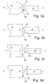
- the piston of the master cylinder (or a piece intermediate integral with the master cylinder) 14 possesses an end 14b having a rounded shape. This end 14b then serves as a rounded element 20.
- the end 13a of the push rod 13 is a surface plane perpendicular to the axis YY 'of the push rod.
- the rounded surface 20 is in contact with the end 13a of the push rod 13 and can slide on this one which makes it possible to retransmit the efforts from the push rod to the piston of the master cylinder without risk of deterioration of the latter or of the booster even if the axes XX 'and YY' are not collinear.
- Figure 3b shows a variant in which end 13a of the push rod is rounded shape and therefore serves as a rounded element 20.
- the end 14b of the piece 14 is a surface plane perpendicular to the axis XX '.
- the rounded element 20 is in contact with the flat surface 14b and can slide on this one.
- an element of rounded shape 20 (spherical for example) is imprisoned in the end 14b of the piece 14.
- the piece 14 (piston for example) is advantageously molded and is example in plastic material.
- the surface 13a of the stem thrust 13 is flat and perpendicular to the axis YY '.
- FIG. 3d provides that the rounded element is fixed (by example by crimping) at the end 13a of the stem of 13.
- the end 14b of the piece 14 is a flat surface perpendicular to the axis XX '.
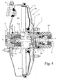
- Figure 4 shows a variant of realization in which the push rod is secured by its end 13b, a cup 12 which is mounted on the piston 5 so as to center the rod of thrust along the axis YY '. This cup is fitted to force or screwed on the piston 5. The position of the rod of thrust is thus determined by the mounting of the cup 12 on the piston.
- the other end 13a of the push rod 13 is free. It goes through a protection plate of entry 17.
Landscapes
- Engineering & Computer Science (AREA)
- Transportation (AREA)
- Mechanical Engineering (AREA)
- Braking Systems And Boosters (AREA)
- Actuator (AREA)
- Pivots And Pivotal Connections (AREA)
- Arrangement Or Mounting Of Control Devices For Change-Speed Gearing (AREA)
- Braking Arrangements (AREA)
Abstract
Description
- une tige de commande susceptible, à partir d'une position de repos, de subir un déplacement suivant une direction axiale sous l'effet d'un effort d'entrée, cette tige étant terminée par un palpeur ;
- un piston pneumatique mobile suivant cette direction axiale, depuis une position de repos, sous l'effet d'une différence de pression commandée par le déplacement axial de la tige de commande, ce piston pneumatique présentant une surface annulaire axiale qui entoure le palpeur ;
- un disque de réaction logé dans une coupelle à fond plat et présentant une face libre sur laquelle la surface annulaire axiale dudit piston pneumatique et le plongeur sont susceptibles d'appliquer des efforts de sortie ;
- une tige de poussée sensiblement axiale dont une première extrémité reçoit ces efforts de sortie et dont une autre extrémité les retransmet à un piston hydraulique du maítre-cylindre ; et
- des moyens de maintien pour assurer que la tige de poussée conserve une direction sensiblement axiale.
- une tige de commande susceptible, à partir d'une position de repos, de subir un déplacement suivant une première direction axiale sous l'effet d'un effort d'entrée, cette tige étant terminée par un palpeur;
- un piston pneumatique mobile suivant cette première direction axiale, depuis une position de repos, sous l'effet d'une différence de pression commandée par le déplacement axial de la tige de commande;
- une tige de poussée orientée sensiblement selon la première direction axiale, une première extrémité de cette tige de poussée recevant les efforts de sortie du piston du servomoteur) et dont une deuxième extrémité retransmet ces efforts contre une extrémité d'un piston hydraulique du maítre-cylindre, le piston hydraulique étant orienté selon une deuxième direction axiale colinéaire ou non avec la première direction axiale.
- la figure 1, une vue en coupe partielle d'un dispositif conforme à l'invention,
- les figures 2a et 2b, des vues agrandies de formes de réalisation du dispositif de centrage axiale d'effort selon l'invention,
- les figures 3a à 3d, des variantes de réalisation du dispositif de l'invention,
- la figure 4, une variante de réalisation du dispositif selon l'invention.
Claims (10)
- Dispositif de centrage axial d'effort pour un ensemble composé d'un servomoteur pneumatique d'assistance au freinage (1) et d'un maítre-cylindre (2), comprenant :caractérisé en ce qu'il comporte un élément de forme arrondie (20) situé entre ledit piston hydraulique (14) et la tige de poussée (13), l'une au moins de ladite extrémité avant (13a) de la tige de poussée ou de ladite extrémité arrière (14b) du piston hydraulique (14) présentant une surface plane perpendiculaire à la première direction axiale (YY') ou à la deuxième direction axiale (XX') respectivement et étant en contact avec l'élément de forme arrondie.une tige de commande (8) susceptible, à partir d'une position de repos, de subir un déplacement suivant une première direction axiale (YY') sous l'effet d'un effort d'entrée, cette tige étant terminée par un palpeur (10) ;un piston pneumatique (5) mobile suivant cette direction axiale (YY'), depuis une position de repos, sous l'effet d'une différence de pression commandée par le déplacement axial de la tige de commande;une tige de poussée (13) orientée sensiblement selon la première direction axiale (YY'), une extrémité arrière (13b) de cette tige de poussée recevant les efforts de sortie du piston (5) du servomoteur (1) et dont une extrémité avant (13a) retransmet ces efforts contre une extrémité arrière (14b) d'un piston hydraulique (14) du maítre-cylindre (2), le piston hydraulique (14) étant orienté selon une deuxième direction axiale (XX') colinéaire ou non avec la première direction axiale;
- Dispositif de centrage axial d'effort selon la revendication 1, caractérisé en ce que ledit élément de forme arrondie (20) est de forme sphérique.
- Dispositif de centrage axial d'effort selon la revendication 1, caractérisé en ce que le dit élément de forme arrondie (20) est l'extrémité avant (13a) de la tige de poussée (13), ou bien ledit élément de forme arrondie est l'extrémité arrière (14b) du piston hydraulique (14).
- Dispositif de centrage axial d'effort selon la revendication 2, caractérisé en ce que ledit élément de forme arrondie (20) est emprisonné dans l'extrémité arrière (14b) du piston hydraulique (14) ou est fixé à l'extrémité avant (13a) de la tige de poussée (13).
- Dispositif de centrage axial d'effort selon la revendication 2, caractérisé en ce que l'extrémité arrière (14b) du piston hydraulique (14) comporte un dispositif de centrage (21) disposé selon la deuxième direction axiale (YY') et dans lequel est placé l'élément de forme arrondie (20).
- Dispositif de centrage axial d'effort selon la revendication 2, caractérisé en ce que l'extrémité avant (13a) de la tige de poussée(13) comporte un dispositif de centrage (21) disposé selon la première direction axiale (XX') et dans lequel est placé l'élément de forme arrondie(20).
- Dispositif de centrage axial d'effort selon l'une des revendications 5 ou 6, caractérisé en ce que le dispositif de centrage de l'élément de forme arrondie (20) comporte une cuvette (21) réalisée à l'extrémité arrière (14b) du piston hydraulique (14) ou à l'extrémité avant (13a) de la tige de poussée (13).
- Dispositif de centrage axial d'effort selon la revendication 7, caractérisé en ce que la cuvette (21) a une forme générale conique, sphérique ou paraboloïde.
- Dispositif de centrage axial d'effort selon l'une des revendications précédentes, caractérisé en ce que l'élément de forme arrondie (20) et l'extrémité de forme plane de la tige de poussée ou du piston hydraulique (13) sont en matériaux de duretés comparables.
- Dispositif de centrage axial d'effort selon l'une quelconque des revendications précédentes, caractérisé en ce que l'élément de forme arrondie (20) sont noyés dans un produit lubrifiant ou enduits d'un produit lubrifiant.
Priority Applications (1)
| Application Number | Priority Date | Filing Date | Title |
|---|---|---|---|
| PL05003849T PL1571059T3 (pl) | 2004-03-02 | 2005-02-23 | Urządzenie do osiowego środkowania w siłowniku pneumatycznym wspomagającym hamowanie zawierające element kulisty |
Applications Claiming Priority (2)
| Application Number | Priority Date | Filing Date | Title |
|---|---|---|---|
| FR0402233A FR2867136B1 (fr) | 2004-03-02 | 2004-03-02 | Transmission d'effort par bille |
| FR0402233 | 2004-03-02 |
Publications (2)
| Publication Number | Publication Date |
|---|---|
| EP1571059A1 true EP1571059A1 (fr) | 2005-09-07 |
| EP1571059B1 EP1571059B1 (fr) | 2006-11-02 |
Family
ID=34746489
Family Applications (1)
| Application Number | Title | Priority Date | Filing Date |
|---|---|---|---|
| EP05003849A Expired - Lifetime EP1571059B1 (fr) | 2004-03-02 | 2005-02-23 | Dispositif de centrage axial pour un servomoteur pneumatique d'assistance auf freinage comprennant une bille |
Country Status (7)
| Country | Link |
|---|---|
| EP (1) | EP1571059B1 (fr) |
| AT (1) | ATE344170T1 (fr) |
| DE (1) | DE602005000214T2 (fr) |
| ES (1) | ES2271919T3 (fr) |
| FR (1) | FR2867136B1 (fr) |
| PL (1) | PL1571059T3 (fr) |
| PT (1) | PT1571059E (fr) |
Cited By (1)
| Publication number | Priority date | Publication date | Assignee | Title |
|---|---|---|---|---|
| FR2900620A1 (fr) * | 2006-05-03 | 2007-11-09 | Peugeot Citroen Automobiles Sa | Servomoteur d'assistance au freinage pour un vehicule automobile |
Families Citing this family (1)
| Publication number | Priority date | Publication date | Assignee | Title |
|---|---|---|---|---|
| KR102635780B1 (ko) * | 2018-09-27 | 2024-02-08 | 현대모비스 주식회사 | 브레이크 부스터 |
Citations (3)
| Publication number | Priority date | Publication date | Assignee | Title |
|---|---|---|---|---|
| US2975775A (en) * | 1956-06-13 | 1961-03-21 | Ford Motor Co | Ball tipped push rod |
| US3983703A (en) * | 1975-10-03 | 1976-10-05 | General Motors Corporation | Master cylinder push rod retention |
| US5761983A (en) * | 1995-08-25 | 1998-06-09 | Jidosha Kiki Co., Ltd. | Output shaft of booster |
-
2004
- 2004-03-02 FR FR0402233A patent/FR2867136B1/fr not_active Expired - Fee Related
-
2005
- 2005-02-23 ES ES05003849T patent/ES2271919T3/es not_active Expired - Lifetime
- 2005-02-23 DE DE602005000214T patent/DE602005000214T2/de not_active Expired - Lifetime
- 2005-02-23 PL PL05003849T patent/PL1571059T3/pl unknown
- 2005-02-23 EP EP05003849A patent/EP1571059B1/fr not_active Expired - Lifetime
- 2005-02-23 PT PT05003849T patent/PT1571059E/pt unknown
- 2005-02-23 AT AT05003849T patent/ATE344170T1/de not_active IP Right Cessation
Patent Citations (3)
| Publication number | Priority date | Publication date | Assignee | Title |
|---|---|---|---|---|
| US2975775A (en) * | 1956-06-13 | 1961-03-21 | Ford Motor Co | Ball tipped push rod |
| US3983703A (en) * | 1975-10-03 | 1976-10-05 | General Motors Corporation | Master cylinder push rod retention |
| US5761983A (en) * | 1995-08-25 | 1998-06-09 | Jidosha Kiki Co., Ltd. | Output shaft of booster |
Cited By (1)
| Publication number | Priority date | Publication date | Assignee | Title |
|---|---|---|---|---|
| FR2900620A1 (fr) * | 2006-05-03 | 2007-11-09 | Peugeot Citroen Automobiles Sa | Servomoteur d'assistance au freinage pour un vehicule automobile |
Also Published As
| Publication number | Publication date |
|---|---|
| FR2867136B1 (fr) | 2006-05-12 |
| PL1571059T3 (pl) | 2007-03-30 |
| DE602005000214T2 (de) | 2007-05-31 |
| EP1571059B1 (fr) | 2006-11-02 |
| PT1571059E (pt) | 2007-01-31 |
| FR2867136A1 (fr) | 2005-09-09 |
| ES2271919T3 (es) | 2007-04-16 |
| ATE344170T1 (de) | 2006-11-15 |
| DE602005000214D1 (de) | 2006-12-14 |
Similar Documents
| Publication | Publication Date | Title |
|---|---|---|
| FR2670733A1 (fr) | Mecanisme de transmission d'une force de reaction pour servo-frein. | |
| FR2480692A1 (fr) | Dispositif de commande pour le mecanisme a soupape d'un servofrein | |
| FR2557527A1 (fr) | Servofrein | |
| EP0352392B1 (fr) | Procédé de réglage de la course morte d'un servomoteur d'assistance au freinage | |
| EP1208025B1 (fr) | Servomoteur pneumatique a auto-assistance selective et controlee en effort | |
| EP0767747B1 (fr) | Ensemble d'un servomoteur pneumatique d'assistance au freinage et d'un maitre-cylindre | |
| EP1571059B1 (fr) | Dispositif de centrage axial pour un servomoteur pneumatique d'assistance auf freinage comprennant une bille | |
| EP1565367B1 (fr) | Procede de reglage d un dispositif de freinage | |
| EP0475794B1 (fr) | Procédé de réglage de la valeur du saut d'un servomoteur pneumatique d'assistance au freinage et servomoteuer pour la mise en oeuvre de ce procédé | |
| EP0462849B1 (fr) | Servomoteur d'assistance à dépression | |
| EP0514224B1 (fr) | Servomoteur pneumatique | |
| EP0047702B1 (fr) | Distributeur pour système de freinage de véhicule, notamment pour véhicule à usage agricole | |
| EP0308310B1 (fr) | Servomoteur d'assistance au freinage | |
| EP1225112B1 (fr) | Amplificateur de force de freinage à double rapport d'amplification pour véhicules automobiles | |
| FR2693420A1 (fr) | Dispositif de transmission d'effort à appui plan. | |
| FR2687972A1 (fr) | Dispositif de servo-assistance pneumatique au freinage a joint de clapet unique et deformable, et servo-frein equipe d'un tel dispositif. | |
| FR2780015A1 (fr) | Servofrein pour vehicule | |
| EP1522478B1 (fr) | Servomoteur d'assistance pneumatique au freinage à course morte réduite et système de freinage comportant un tel servomoteur | |
| EP2058196B1 (fr) | Palpeur pour servomoteur d'assistance au freinage | |
| EP1361126B1 (fr) | Servomoteur d'assistance pneumatique au freinage comportant un dispositif d'assistance au freinage d'urgence à niveau de bruit de fonctionnement réduit | |
| EP1564098A1 (fr) | Système de commande de freinage comportant un maítre-cylindre et un amplificateur de force a différentiel de pression | |
| EP1578653A1 (fr) | Servomoteur d assistance au freinage, son procede de fabrica tion et dispositif | |
| FR2864504A1 (fr) | Servomoteur de freinage a saut reglable et procede de reglage dudit servomoteur. | |
| FR2660274A1 (fr) | Procede de reglage de la valeur du saut d'un servomoteur d'assistance au freinage. | |
| EP1420990A1 (fr) | Servomoteur a soupapes |
Legal Events
| Date | Code | Title | Description |
|---|---|---|---|
| PUAI | Public reference made under article 153(3) epc to a published international application that has entered the european phase |
Free format text: ORIGINAL CODE: 0009012 |
|
| AK | Designated contracting states |
Kind code of ref document: A1 Designated state(s): AT BE BG CH CY CZ DE DK EE ES FI FR GB GR HU IE IS IT LI LT LU MC NL PL PT RO SE SI SK TR |
|
| AX | Request for extension of the european patent |
Extension state: AL BA HR LV MK YU |
|
| 17P | Request for examination filed |
Effective date: 20060307 |
|
| AKX | Designation fees paid |
Designated state(s): AT BE BG CH CY CZ DE DK EE ES FI FR GB GR HU IE IS IT LI LT LU MC NL PL PT RO SE SI SK TR |
|
| GRAP | Despatch of communication of intention to grant a patent |
Free format text: ORIGINAL CODE: EPIDOSNIGR1 |
|
| GRAS | Grant fee paid |
Free format text: ORIGINAL CODE: EPIDOSNIGR3 |
|
| GRAA | (expected) grant |
Free format text: ORIGINAL CODE: 0009210 |
|
| AK | Designated contracting states |
Kind code of ref document: B1 Designated state(s): AT BE BG CH CY CZ DE DK EE ES FI FR GB GR HU IE IS IT LI LT LU MC NL PL PT RO SE SI SK TR |
|
| PG25 | Lapsed in a contracting state [announced via postgrant information from national office to epo] |
Ref country code: IE Free format text: LAPSE BECAUSE OF FAILURE TO SUBMIT A TRANSLATION OF THE DESCRIPTION OR TO PAY THE FEE WITHIN THE PRESCRIBED TIME-LIMIT Effective date: 20061102 Ref country code: RO Free format text: LAPSE BECAUSE OF FAILURE TO SUBMIT A TRANSLATION OF THE DESCRIPTION OR TO PAY THE FEE WITHIN THE PRESCRIBED TIME-LIMIT Effective date: 20061102 Ref country code: LT Free format text: LAPSE BECAUSE OF FAILURE TO SUBMIT A TRANSLATION OF THE DESCRIPTION OR TO PAY THE FEE WITHIN THE PRESCRIBED TIME-LIMIT Effective date: 20061102 Ref country code: CZ Free format text: LAPSE BECAUSE OF FAILURE TO SUBMIT A TRANSLATION OF THE DESCRIPTION OR TO PAY THE FEE WITHIN THE PRESCRIBED TIME-LIMIT Effective date: 20061102 Ref country code: FI Free format text: LAPSE BECAUSE OF FAILURE TO SUBMIT A TRANSLATION OF THE DESCRIPTION OR TO PAY THE FEE WITHIN THE PRESCRIBED TIME-LIMIT Effective date: 20061102 Ref country code: SI Free format text: LAPSE BECAUSE OF FAILURE TO SUBMIT A TRANSLATION OF THE DESCRIPTION OR TO PAY THE FEE WITHIN THE PRESCRIBED TIME-LIMIT Effective date: 20061102 Ref country code: AT Free format text: LAPSE BECAUSE OF FAILURE TO SUBMIT A TRANSLATION OF THE DESCRIPTION OR TO PAY THE FEE WITHIN THE PRESCRIBED TIME-LIMIT Effective date: 20061102 Ref country code: SK Free format text: LAPSE BECAUSE OF FAILURE TO SUBMIT A TRANSLATION OF THE DESCRIPTION OR TO PAY THE FEE WITHIN THE PRESCRIBED TIME-LIMIT Effective date: 20061102 |
|
| REG | Reference to a national code |
Ref country code: GB Ref legal event code: FG4D Free format text: NOT ENGLISH |
|
| REG | Reference to a national code |
Ref country code: IE Ref legal event code: FG4D Free format text: LANGUAGE OF EP DOCUMENT: FRENCH |
|
| REG | Reference to a national code |
Ref country code: CH Ref legal event code: EP |
|
| REF | Corresponds to: |
Ref document number: 602005000214 Country of ref document: DE Date of ref document: 20061214 Kind code of ref document: P |
|
| GBT | Gb: translation of ep patent filed (gb section 77(6)(a)/1977) |
Effective date: 20061129 |
|
| REG | Reference to a national code |
Ref country code: PT Ref legal event code: SC4A Free format text: AVAILABILITY OF NATIONAL TRANSLATION Effective date: 20061213 |
|
| PG25 | Lapsed in a contracting state [announced via postgrant information from national office to epo] |
Ref country code: DK Free format text: LAPSE BECAUSE OF FAILURE TO SUBMIT A TRANSLATION OF THE DESCRIPTION OR TO PAY THE FEE WITHIN THE PRESCRIBED TIME-LIMIT Effective date: 20070202 Ref country code: BG Free format text: LAPSE BECAUSE OF FAILURE TO SUBMIT A TRANSLATION OF THE DESCRIPTION OR TO PAY THE FEE WITHIN THE PRESCRIBED TIME-LIMIT Effective date: 20070202 Ref country code: SE Free format text: LAPSE BECAUSE OF FAILURE TO SUBMIT A TRANSLATION OF THE DESCRIPTION OR TO PAY THE FEE WITHIN THE PRESCRIBED TIME-LIMIT Effective date: 20070202 |
|
| PG25 | Lapsed in a contracting state [announced via postgrant information from national office to epo] |
Ref country code: MC Free format text: LAPSE BECAUSE OF NON-PAYMENT OF DUE FEES Effective date: 20070228 |
|
| PG25 | Lapsed in a contracting state [announced via postgrant information from national office to epo] |
Ref country code: IS Free format text: LAPSE BECAUSE OF FAILURE TO SUBMIT A TRANSLATION OF THE DESCRIPTION OR TO PAY THE FEE WITHIN THE PRESCRIBED TIME-LIMIT Effective date: 20070302 |
|
| REG | Reference to a national code |
Ref country code: PL Ref legal event code: T3 |
|
| REG | Reference to a national code |
Ref country code: ES Ref legal event code: FG2A Ref document number: 2271919 Country of ref document: ES Kind code of ref document: T3 |
|
| REG | Reference to a national code |
Ref country code: IE Ref legal event code: FD4D |
|
| PLBE | No opposition filed within time limit |
Free format text: ORIGINAL CODE: 0009261 |
|
| STAA | Information on the status of an ep patent application or granted ep patent |
Free format text: STATUS: NO OPPOSITION FILED WITHIN TIME LIMIT |
|
| 26N | No opposition filed |
Effective date: 20070803 |
|
| BERE | Be: lapsed |
Owner name: ROBERT BOSCH G.M.B.H. Effective date: 20070228 |
|
| PG25 | Lapsed in a contracting state [announced via postgrant information from national office to epo] |
Ref country code: BE Free format text: LAPSE BECAUSE OF NON-PAYMENT OF DUE FEES Effective date: 20070228 |
|
| PG25 | Lapsed in a contracting state [announced via postgrant information from national office to epo] |
Ref country code: GR Free format text: LAPSE BECAUSE OF FAILURE TO SUBMIT A TRANSLATION OF THE DESCRIPTION OR TO PAY THE FEE WITHIN THE PRESCRIBED TIME-LIMIT Effective date: 20070203 |
|
| PG25 | Lapsed in a contracting state [announced via postgrant information from national office to epo] |
Ref country code: EE Free format text: LAPSE BECAUSE OF FAILURE TO SUBMIT A TRANSLATION OF THE DESCRIPTION OR TO PAY THE FEE WITHIN THE PRESCRIBED TIME-LIMIT Effective date: 20061102 |
|
| PG25 | Lapsed in a contracting state [announced via postgrant information from national office to epo] |
Ref country code: LU Free format text: LAPSE BECAUSE OF NON-PAYMENT OF DUE FEES Effective date: 20070223 Ref country code: CY Free format text: LAPSE BECAUSE OF FAILURE TO SUBMIT A TRANSLATION OF THE DESCRIPTION OR TO PAY THE FEE WITHIN THE PRESCRIBED TIME-LIMIT Effective date: 20061102 |
|
| PG25 | Lapsed in a contracting state [announced via postgrant information from national office to epo] |
Ref country code: HU Free format text: LAPSE BECAUSE OF FAILURE TO SUBMIT A TRANSLATION OF THE DESCRIPTION OR TO PAY THE FEE WITHIN THE PRESCRIBED TIME-LIMIT Effective date: 20070503 |
|
| REG | Reference to a national code |
Ref country code: CH Ref legal event code: PL |
|
| PG25 | Lapsed in a contracting state [announced via postgrant information from national office to epo] |
Ref country code: LI Free format text: LAPSE BECAUSE OF NON-PAYMENT OF DUE FEES Effective date: 20090228 Ref country code: CH Free format text: LAPSE BECAUSE OF NON-PAYMENT OF DUE FEES Effective date: 20090228 |
|
| PGFP | Annual fee paid to national office [announced via postgrant information from national office to epo] |
Ref country code: FR Payment date: 20140218 Year of fee payment: 10 |
|
| PGFP | Annual fee paid to national office [announced via postgrant information from national office to epo] |
Ref country code: NL Payment date: 20150223 Year of fee payment: 11 |
|
| PGFP | Annual fee paid to national office [announced via postgrant information from national office to epo] |
Ref country code: IT Payment date: 20150223 Year of fee payment: 11 Ref country code: PT Payment date: 20150212 Year of fee payment: 11 |
|
| PGFP | Annual fee paid to national office [announced via postgrant information from national office to epo] |
Ref country code: TR Payment date: 20150212 Year of fee payment: 11 |
|
| REG | Reference to a national code |
Ref country code: FR Ref legal event code: ST Effective date: 20151030 |
|
| PG25 | Lapsed in a contracting state [announced via postgrant information from national office to epo] |
Ref country code: FR Free format text: LAPSE BECAUSE OF NON-PAYMENT OF DUE FEES Effective date: 20150302 |
|
| PGFP | Annual fee paid to national office [announced via postgrant information from national office to epo] |
Ref country code: ES Payment date: 20160223 Year of fee payment: 12 |
|
| PGFP | Annual fee paid to national office [announced via postgrant information from national office to epo] |
Ref country code: PL Payment date: 20160215 Year of fee payment: 12 Ref country code: GB Payment date: 20160222 Year of fee payment: 12 |
|
| PGFP | Annual fee paid to national office [announced via postgrant information from national office to epo] |
Ref country code: DE Payment date: 20160426 Year of fee payment: 12 |
|
| REG | Reference to a national code |
Ref country code: NL Ref legal event code: MM Effective date: 20160301 |
|
| PG25 | Lapsed in a contracting state [announced via postgrant information from national office to epo] |
Ref country code: PT Free format text: LAPSE BECAUSE OF NON-PAYMENT OF DUE FEES Effective date: 20160823 |
|
| PG25 | Lapsed in a contracting state [announced via postgrant information from national office to epo] |
Ref country code: IT Free format text: LAPSE BECAUSE OF NON-PAYMENT OF DUE FEES Effective date: 20160223 |
|
| PG25 | Lapsed in a contracting state [announced via postgrant information from national office to epo] |
Ref country code: NL Free format text: LAPSE BECAUSE OF NON-PAYMENT OF DUE FEES Effective date: 20160301 |
|
| REG | Reference to a national code |
Ref country code: DE Ref legal event code: R119 Ref document number: 602005000214 Country of ref document: DE |
|
| GBPC | Gb: european patent ceased through non-payment of renewal fee |
Effective date: 20170223 |
|
| PG25 | Lapsed in a contracting state [announced via postgrant information from national office to epo] |
Ref country code: DE Free format text: LAPSE BECAUSE OF NON-PAYMENT OF DUE FEES Effective date: 20170901 |
|
| PG25 | Lapsed in a contracting state [announced via postgrant information from national office to epo] |
Ref country code: GB Free format text: LAPSE BECAUSE OF NON-PAYMENT OF DUE FEES Effective date: 20170223 |
|
| REG | Reference to a national code |
Ref country code: ES Ref legal event code: FD2A Effective date: 20180705 |
|
| PG25 | Lapsed in a contracting state [announced via postgrant information from national office to epo] |
Ref country code: ES Free format text: LAPSE BECAUSE OF NON-PAYMENT OF DUE FEES Effective date: 20170224 |
|
| PG25 | Lapsed in a contracting state [announced via postgrant information from national office to epo] |
Ref country code: PL Free format text: LAPSE BECAUSE OF NON-PAYMENT OF DUE FEES Effective date: 20170223 |
|
| PG25 | Lapsed in a contracting state [announced via postgrant information from national office to epo] |
Ref country code: TR Free format text: LAPSE BECAUSE OF NON-PAYMENT OF DUE FEES Effective date: 20160223 |