EP1571035A1 - Adjustable vehicle seat, and vehicle equipped with such an adjustable seat - Google Patents
Adjustable vehicle seat, and vehicle equipped with such an adjustable seat Download PDFInfo
- Publication number
- EP1571035A1 EP1571035A1 EP04425135A EP04425135A EP1571035A1 EP 1571035 A1 EP1571035 A1 EP 1571035A1 EP 04425135 A EP04425135 A EP 04425135A EP 04425135 A EP04425135 A EP 04425135A EP 1571035 A1 EP1571035 A1 EP 1571035A1
- Authority
- EP
- European Patent Office
- Prior art keywords
- seat
- backrest
- vehicle
- operating configuration
- seat portion
- Prior art date
- Legal status (The legal status is an assumption and is not a legal conclusion. Google has not performed a legal analysis and makes no representation as to the accuracy of the status listed.)
- Granted
Links
Images


Classifications
-
- B—PERFORMING OPERATIONS; TRANSPORTING
- B60—VEHICLES IN GENERAL
- B60N—SEATS SPECIALLY ADAPTED FOR VEHICLES; VEHICLE PASSENGER ACCOMMODATION NOT OTHERWISE PROVIDED FOR
- B60N2/00—Seats specially adapted for vehicles; Arrangement or mounting of seats in vehicles
- B60N2/24—Seats specially adapted for vehicles; Arrangement or mounting of seats in vehicles for particular purposes or particular vehicles
- B60N2/30—Non-dismountable or dismountable seats storable in a non-use position, e.g. foldable spare seats
- B60N2/3088—Non-dismountable or dismountable seats storable in a non-use position, e.g. foldable spare seats characterised by the mechanical link
- B60N2/3093—Non-dismountable or dismountable seats storable in a non-use position, e.g. foldable spare seats characterised by the mechanical link slides
-
- B—PERFORMING OPERATIONS; TRANSPORTING
- B60—VEHICLES IN GENERAL
- B60N—SEATS SPECIALLY ADAPTED FOR VEHICLES; VEHICLE PASSENGER ACCOMMODATION NOT OTHERWISE PROVIDED FOR
- B60N2/00—Seats specially adapted for vehicles; Arrangement or mounting of seats in vehicles
- B60N2/24—Seats specially adapted for vehicles; Arrangement or mounting of seats in vehicles for particular purposes or particular vehicles
- B60N2/30—Non-dismountable or dismountable seats storable in a non-use position, e.g. foldable spare seats
- B60N2/3002—Non-dismountable or dismountable seats storable in a non-use position, e.g. foldable spare seats back-rest movements
- B60N2/3004—Non-dismountable or dismountable seats storable in a non-use position, e.g. foldable spare seats back-rest movements by rotation only
- B60N2/3009—Non-dismountable or dismountable seats storable in a non-use position, e.g. foldable spare seats back-rest movements by rotation only about transversal axis
- B60N2/3013—Non-dismountable or dismountable seats storable in a non-use position, e.g. foldable spare seats back-rest movements by rotation only about transversal axis the back-rest being hinged on the vehicle frame
- B60N2/3015—Non-dismountable or dismountable seats storable in a non-use position, e.g. foldable spare seats back-rest movements by rotation only about transversal axis the back-rest being hinged on the vehicle frame the axis being located at the top of the back-rest
-
- B—PERFORMING OPERATIONS; TRANSPORTING
- B60—VEHICLES IN GENERAL
- B60N—SEATS SPECIALLY ADAPTED FOR VEHICLES; VEHICLE PASSENGER ACCOMMODATION NOT OTHERWISE PROVIDED FOR
- B60N2/00—Seats specially adapted for vehicles; Arrangement or mounting of seats in vehicles
- B60N2/24—Seats specially adapted for vehicles; Arrangement or mounting of seats in vehicles for particular purposes or particular vehicles
- B60N2/30—Non-dismountable or dismountable seats storable in a non-use position, e.g. foldable spare seats
- B60N2/3002—Non-dismountable or dismountable seats storable in a non-use position, e.g. foldable spare seats back-rest movements
- B60N2/3029—Non-dismountable or dismountable seats storable in a non-use position, e.g. foldable spare seats back-rest movements by composed movement
- B60N2/3031—Non-dismountable or dismountable seats storable in a non-use position, e.g. foldable spare seats back-rest movements by composed movement in a longitudinal-vertical plane
-
- B—PERFORMING OPERATIONS; TRANSPORTING
- B60—VEHICLES IN GENERAL
- B60N—SEATS SPECIALLY ADAPTED FOR VEHICLES; VEHICLE PASSENGER ACCOMMODATION NOT OTHERWISE PROVIDED FOR
- B60N2/00—Seats specially adapted for vehicles; Arrangement or mounting of seats in vehicles
- B60N2/24—Seats specially adapted for vehicles; Arrangement or mounting of seats in vehicles for particular purposes or particular vehicles
- B60N2/30—Non-dismountable or dismountable seats storable in a non-use position, e.g. foldable spare seats
- B60N2/3038—Cushion movements
- B60N2/304—Cushion movements by rotation only
- B60N2/3045—Cushion movements by rotation only about transversal axis
- B60N2/305—Cushion movements by rotation only about transversal axis the cushion being hinged on the vehicle frame
-
- B—PERFORMING OPERATIONS; TRANSPORTING
- B60—VEHICLES IN GENERAL
- B60N—SEATS SPECIALLY ADAPTED FOR VEHICLES; VEHICLE PASSENGER ACCOMMODATION NOT OTHERWISE PROVIDED FOR
- B60N2/00—Seats specially adapted for vehicles; Arrangement or mounting of seats in vehicles
- B60N2/24—Seats specially adapted for vehicles; Arrangement or mounting of seats in vehicles for particular purposes or particular vehicles
- B60N2/30—Non-dismountable or dismountable seats storable in a non-use position, e.g. foldable spare seats
- B60N2/3038—Cushion movements
- B60N2/3063—Cushion movements by composed movement
- B60N2/3065—Cushion movements by composed movement in a longitudinal-vertical plane
-
- B—PERFORMING OPERATIONS; TRANSPORTING
- B60—VEHICLES IN GENERAL
- B60N—SEATS SPECIALLY ADAPTED FOR VEHICLES; VEHICLE PASSENGER ACCOMMODATION NOT OTHERWISE PROVIDED FOR
- B60N2/00—Seats specially adapted for vehicles; Arrangement or mounting of seats in vehicles
- B60N2/24—Seats specially adapted for vehicles; Arrangement or mounting of seats in vehicles for particular purposes or particular vehicles
- B60N2/30—Non-dismountable or dismountable seats storable in a non-use position, e.g. foldable spare seats
- B60N2/3088—Non-dismountable or dismountable seats storable in a non-use position, e.g. foldable spare seats characterised by the mechanical link
- B60N2/309—Non-dismountable or dismountable seats storable in a non-use position, e.g. foldable spare seats characterised by the mechanical link rods
-
- B—PERFORMING OPERATIONS; TRANSPORTING
- B60—VEHICLES IN GENERAL
- B60N—SEATS SPECIALLY ADAPTED FOR VEHICLES; VEHICLE PASSENGER ACCOMMODATION NOT OTHERWISE PROVIDED FOR
- B60N2/00—Seats specially adapted for vehicles; Arrangement or mounting of seats in vehicles
- B60N2/80—Head-rests
- B60N2/806—Head-rests movable or adjustable
- B60N2/809—Head-rests movable or adjustable vertically slidable
- B60N2/832—Head-rests movable or adjustable vertically slidable movable to an inoperative or stowed position
- B60N2/835—Head-rests movable or adjustable vertically slidable movable to an inoperative or stowed position specially adapted for rear seats
Definitions
- the present invention relates to an adjustable vehicle seat.
- Some vehicles are equipped with a drop-down rear seat, which, when necessary, can be rotated into a position in which the backrest and seat portion of the seat are folded one on top of the other and normally stowed against the front seats to enlarge the luggage compartment.
- an adjustable seat for a vehicle comprising a seat portion and a backrest, and being characterized by being movable between a first operating configuration, in which said seat portion and said backrest define accommodation for at least one passenger, and a second operating configuration, in which said seat portion defines the front of a rear loading compartment of said vehicle, and the backrest defines the top of said loading compartment.
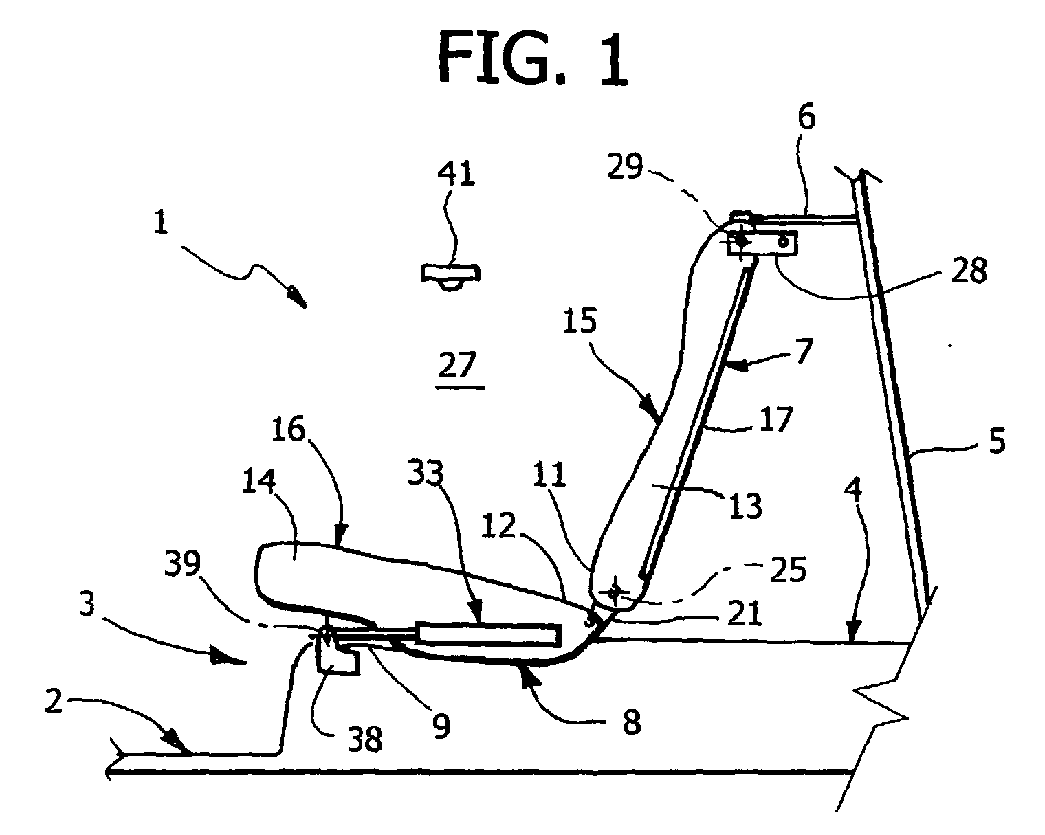
- Number 1 in Figures 1 to 5 indicates an adjustable rear seat of a vehicle 2 (shown partly and schematically) comprising a passenger compartment 3, and a luggage compartment 4 behind seat 1.
- Luggage compartment 4 is closed at the rear by a door 5, is defined at the top by a substantially horizontal parcel shelf 6, and is extendable by adjusting seat 1.
- Seat 1 comprises a backrest 7 and a seat portion 8, and is movable between a first ( Figure 1) and a second ( Figure 4) operating configuration.
- seat 1 defines accommodation in passenger compartment 3 for at least one rear passenger
- backrest 7 defines the front of luggage compartment 4
- seat portion 8 rests on a wall 9 defining an extension of the loading bed of luggage compartment 4.
- backrest 7 is substantially aligned with parcel shelf 6 to define the top of an additional compartment 10 formed over wall 9 frontwards of luggage compartment 4, and seat portion 8 defines the front of compartment 10. More specifically, backrest 7 and seat portion 8 comprise respective adjacent end portions 11, 12 closing compartment 10.
- Backrest 7 and seat portion 8 comprise respective cushion bodies 13, 14 defining respective supporting surfaces 15, 16, which face each other in the first operating configuration, and face opposite ways in the second operating configuration, i.e. face the roof (not shown) and the front seats (not shown) of vehicle 2.
- backrest 7 and seat portion 8 also comprise respective frames 17, 18, which support respective bodies 13, 14, and which are connected to each other by a pair of brackets 21 when moving between the first and second operating configuration.
- Brackets 21 are connected integrally to a rear end portion 22 of frame 18, project from body 14 and into body 13 through respective openings (not shown), and are hinged to a bottom end portion 24 of frame 17 to allow backrest 7 and seat portion 8 to rotate with respect to each other about a horizontal hinge axis 25 perpendicular to the travelling direction (not shown) of vehicle 2.
- Frame 17 comprises a top end portion 26 connected to the side panel 27 of vehicle 2 by a lock device 28, which is releasable to recline backrest 7 about axis 25 onto surface 16.
- Frame 17 is hinged to side panel 27 with the interposition of device 28 to rotate about a fixed axis 29, parallel to axis 25, when moving between said two operating configurations, and is fitted with a headrest 30 movable, in a direction perpendicular to axis 29, between a lowered rest position, in which it is housed completely inside a recess 31 in body 13 to avoid interfering with parcel shelf 6 when rotating about axis 29, and a raised operating position (not shown), in which it projects at least partly from recess 31 to define a support for a passenger's head.
- seat portion 8 comprises an anchoring device 32 fitted to frame 18, and which releasably engages a stop (not shown) on wall 9 to retain seat portion 8 in the first operating configuration.
- Seat portion 8 also comprises two piston members 33, in turn comprising respective guide cylinders 34 fixed to frame 18, and respective rods 35, the ends 36 of which project from body 14 through respective openings (not shown) and are hinged to respective brackets 38 fixed to wall 9 to allow seat portion 8 to rotate about a fixed axis 39 of rotation, parallel to axis 25, when moving between said two operating configurations.
- Rods 35 are connected to cylinders 34 to slide in directions 40 perpendicular to axes 25 and 39, and are pushed into an extracted position by respective elastic devices (not shown), e.g. springs or compressible fluid volumes, housed inside cylinders 34 and such as to move seat 1 into one of said two operating configurations when a dead centre position, in which seat portion 8 and backrest 7 are substantially aligned ( Figure 3), is exceeded.
- elastic devices e.g. springs or compressible fluid volumes
- one of portions 11, 12 is fitted with a grip (not shown) which, once device 32 is released, is pulled manually to move seat 1 from the first to the second operating configuration.
- a grip not shown
- cylinders 34 move forwards with respect to rods 35 to guide seat portion 8 parallel to directions 40, while seat portion 8 and backrest 7 rotate about respective axes 39 and 29 into said dead centre position ( Figure 3).
- seat 1 has no member 41, and is retained in the second operating configuration by the thrust exerted by piston members 33.
- seat 1 is released from member 41, if provided, and portions 11, 12 are pushed from passenger compartment 3 into said dead centre position, past which seat portion 8 is brought to rest on wall 9, along a trajectory substantially opposite to the one described above, by the elastic devices compressed inside piston members 33.
- FIGS 6 to 9 show a variation of seat 1, the component parts of which are indicated, where possible, using the same reference numbers as in Figures 1 to 5.
- frame 18 has no piston members 33, and comprises a front end portion (not shown) hinged directly to brackets 38 about axis 39; and portion 26 is fitted to side panel 27 by parcel shelf 6, which rests on a supporting member 43 which substitutes for member 41. More specifically, parcel shelf 6 defines a connecting rod hinged at the front end to backrest 7 about a movable axis 29a parallel to axis 25, and at the rear end to side panel 27 about a fixed axis 29b parallel to axis 25.
- backrest 7 Being connected by parcel shelf 6, backrest 7 is movable tangentially with respect to axis 29b when moving seat 1 between said two operating configurations, so that, once device 32 is released, portion 12 of seat portion 8, and therefore backrest 7, can be raised manually to rotate parcel shelf 6 about axis 29b and off member 43 ( Figure 7).
- backrest 7 is detachable from side panel 27, e.g. by releasing the rear end of parcel shelf 6 from side panel 27, and can be rotated about axis 25 and reclined on surface 16.
- Seat 1 thus provides for exploiting the space inside vehicle 2 differently and to the best advantage according to specific user requirements - passenger accommodation or luggage transportation - and is perfectly functional in all operating conditions.
- seat 1 not only provides for rear passenger accommodation, but also for defining the front of compartment 10. That is, in the second operating configuration, seat 1 is adjacent on one side to parcel shelf 6, and on the other to wall 9, so as to fully enclose the space defined by luggage compartment 4 and additional compartment 10, conceal the content of the two compartments from the outside, and at the same time prevent luggage from sliding inside passenger compartment 3 when vehicle 2 is moving, e.g. in the event of an accident or sharp braking.
- seat 1 occupies little space and permits correct adjustment of the front seats. Finally, seat 1 is easy to move between the two operating configurations, on account of seat portion 8 and backrest 7, when so doing, remaining hinged to each other and connected to wall 9 and side panel 27.
- piston members 33 or parcel shelf 6 allow seat 1 an additional degree of freedom enabling displacement of seat portion 8 and backrest 7 while hinged to each other and to vehicle 2.
- device 32 provides for safe connection of seat 1 to wall 9, while headrest 30 is practical and compact by virtue of recess 31.
- seat 1 may be released from wall 9 or from side panel 27, or seat portion 8 and backrest 7 may be released, before moving seat 1 between the two operating configurations, and then locked back together in the desired operating configuration.
- Said additional degree of freedom i.e. the ability to translate perpendicularly to axes 39, 29 or 29b, may be provided by systems other than piston members 33 and parcel shelf 6, and possibly connected to portions of backrest 1 other than those described.
- a sliding coupling may be provided between two adjacent portions forming part of seat portion 8, backrest 7, or parcel shelf 6; or a guide and slide system may be interposed between axis 39 and wall 9; or a guide and slide system may be associated with backrest 7 as opposed to seat portion 8; or a lever mechanism other than parcel shelf 6 may be provided, e.g. an articulated quadrilateral, possibly associated with seat portion 8 as opposed to backrest 7.
- Backrest 7 and seat portion 8 may be divided into a right and left lateral element, or cover the whole width of vehicle 2 between side panels 27.
- seat 1 may be anchored in the first operating configuration by members other than device 32, and/or may be rotated about axis 39 and stowed against the front seats after folding backrest 7 down onto surface 15.
Landscapes
- Engineering & Computer Science (AREA)
- Aviation & Aerospace Engineering (AREA)
- Transportation (AREA)
- Mechanical Engineering (AREA)
- Seats For Vehicles (AREA)
Abstract
Description
- The present invention relates to an adjustable vehicle seat.
- As is known, depending on circumstances, some vehicle users require maximum passenger space, while others require a relatively large luggage compartment. Consequently, the space at the rear of the vehicle must be exploited to maximum advantage, and in particular to adapt the vehicle to specific user requirements.
- Some vehicles are equipped with a drop-down rear seat, which, when necessary, can be rotated into a position in which the backrest and seat portion of the seat are folded one on top of the other and normally stowed against the front seats to enlarge the luggage compartment.
- When stowed against the front seats, known drop-down rear seats of the above type tend to impair adjustment of the front seats, and are unsatisfactory in terms of luggage retention.
- It is an object of the present invention to provide an adjustable vehicle seat designed to provide a straightforward, low-cost solution to the above problems.
- According to the present invention, there is provided an adjustable seat for a vehicle; the seat comprising a seat portion and a backrest, and being characterized by being movable between a first operating configuration, in which said seat portion and said backrest define accommodation for at least one passenger, and a second operating configuration, in which said seat portion defines the front of a rear loading compartment of said vehicle, and the backrest defines the top of said loading compartment.
- A non-limiting embodiment of the invention will be described by way of example with reference to the accompanying drawings, in which:
- Figures 1 to 4 show schematic side views of a preferred embodiment of the adjustable vehicle seat according to the present invention, and a sequence of operations to adjust the seat;
- Figure 5 shows a larger-scale view in perspective, with parts removed for clarity, of the Figure 1-4 seat;
- Figures 6 to 9 are similar to, and show a variation of the adjustable seat in, Figures 1 to 4.
-
-
Number 1 in Figures 1 to 5 indicates an adjustable rear seat of a vehicle 2 (shown partly and schematically) comprising apassenger compartment 3, and aluggage compartment 4 behindseat 1.Luggage compartment 4 is closed at the rear by adoor 5, is defined at the top by a substantiallyhorizontal parcel shelf 6, and is extendable by adjustingseat 1. -
Seat 1 comprises abackrest 7 and aseat portion 8, and is movable between a first (Figure 1) and a second (Figure 4) operating configuration. In the first configuration,seat 1 defines accommodation inpassenger compartment 3 for at least one rear passenger,backrest 7 defines the front ofluggage compartment 4, andseat portion 8 rests on awall 9 defining an extension of the loading bed ofluggage compartment 4. In the second operating configuration,backrest 7 is substantially aligned withparcel shelf 6 to define the top of anadditional compartment 10 formed overwall 9 frontwards ofluggage compartment 4, andseat portion 8 defines the front ofcompartment 10. More specifically,backrest 7 andseat portion 8 comprise respectiveadjacent end portions closing compartment 10. -
Backrest 7 andseat portion 8 compriserespective cushion bodies surfaces vehicle 2. - With reference to Figure 5,
backrest 7 andseat portion 8 also compriserespective frames respective bodies brackets 21 when moving between the first and second operating configuration.Brackets 21 are connected integrally to arear end portion 22 offrame 18, project frombody 14 and intobody 13 through respective openings (not shown), and are hinged to abottom end portion 24 offrame 17 to allowbackrest 7 andseat portion 8 to rotate with respect to each other about ahorizontal hinge axis 25 perpendicular to the travelling direction (not shown) ofvehicle 2. -
Frame 17 comprises atop end portion 26 connected to theside panel 27 ofvehicle 2 by alock device 28, which is releasable to reclinebackrest 7 aboutaxis 25 ontosurface 16. -
Frame 17 is hinged toside panel 27 with the interposition ofdevice 28 to rotate about afixed axis 29, parallel toaxis 25, when moving between said two operating configurations, and is fitted with aheadrest 30 movable, in a direction perpendicular toaxis 29, between a lowered rest position, in which it is housed completely inside arecess 31 inbody 13 to avoid interfering withparcel shelf 6 when rotating aboutaxis 29, and a raised operating position (not shown), in which it projects at least partly fromrecess 31 to define a support for a passenger's head. - With reference to Figure 5,
seat portion 8 comprises ananchoring device 32 fitted toframe 18, and which releasably engages a stop (not shown) onwall 9 to retainseat portion 8 in the first operating configuration.Seat portion 8 also comprises twopiston members 33, in turn comprisingrespective guide cylinders 34 fixed toframe 18, andrespective rods 35, theends 36 of which project frombody 14 through respective openings (not shown) and are hinged torespective brackets 38 fixed towall 9 to allowseat portion 8 to rotate about afixed axis 39 of rotation, parallel toaxis 25, when moving between said two operating configurations. -
Rods 35 are connected tocylinders 34 to slide indirections 40 perpendicular toaxes cylinders 34 and such as to moveseat 1 into one of said two operating configurations when a dead centre position, in whichseat portion 8 andbackrest 7 are substantially aligned (Figure 3), is exceeded. - With reference to Figures 1 to 4, one of
portions device 32 is released, is pulled manually to moveseat 1 from the first to the second operating configuration. Over a first portion of the above movement (Figure 2),cylinders 34 move forwards with respect torods 35 to guideseat portion 8 parallel todirections 40, whileseat portion 8 andbackrest 7 rotate aboutrespective axes - Once the dead centre position is exceeded, the elastic devices compressed inside
piston members 33expel rods 35 fromcylinders 34, possibly in damped manner, to rotateseat portion 8 andbackrest 7 further aboutaxes portion 11, travelling along its own trajectory, engages a retaining member 41 (shown schematically) fixed toside panel 27. - In one variation,
seat 1 has nomember 41, and is retained in the second operating configuration by the thrust exerted bypiston members 33. - To return to the first operating configuration,
seat 1 is released frommember 41, if provided, andportions passenger compartment 3 into said dead centre position, past whichseat portion 8 is brought to rest onwall 9, along a trajectory substantially opposite to the one described above, by the elastic devices compressed insidepiston members 33. - Figures 6 to 9 show a variation of
seat 1, the component parts of which are indicated, where possible, using the same reference numbers as in Figures 1 to 5. - Unlike the Figure 1-5 solution,
frame 18 has nopiston members 33, and comprises a front end portion (not shown) hinged directly tobrackets 38 aboutaxis 39; andportion 26 is fitted toside panel 27 byparcel shelf 6, which rests on a supportingmember 43 which substitutes formember 41. More specifically,parcel shelf 6 defines a connecting rod hinged at the front end tobackrest 7 about amovable axis 29a parallel toaxis 25, and at the rear end toside panel 27 about afixed axis 29b parallel toaxis 25. - Being connected by
parcel shelf 6,backrest 7 is movable tangentially with respect toaxis 29b when movingseat 1 between said two operating configurations, so that, oncedevice 32 is released,portion 12 ofseat portion 8, and thereforebackrest 7, can be raised manually to rotateparcel shelf 6 aboutaxis 29b and off member 43 (Figure 7). - As
portion 12 is rotated further forwards aboutaxis 39, the dead centre position is reached in whichbackrest 7 andseat portion 8 are aligned (Figure 8), and past whichbackrest 7 continues along its rotation-translation trajectory, while the rotation direction ofparcel shelf 6 aboutaxis 29b is inverted untilparcel shelf 6 andbackrest 7 are eventually positioned horizontally, substantially aligned with each other, and supported bymember 43. - As in the Figure 1-5 solution,
backrest 7 is detachable fromside panel 27, e.g. by releasing the rear end ofparcel shelf 6 fromside panel 27, and can be rotated aboutaxis 25 and reclined onsurface 16. -
Seat 1 thus provides for exploiting the space insidevehicle 2 differently and to the best advantage according to specific user requirements - passenger accommodation or luggage transportation - and is perfectly functional in all operating conditions. - More specifically,
seat 1 not only provides for rear passenger accommodation, but also for defining the front ofcompartment 10. That is, in the second operating configuration,seat 1 is adjacent on one side toparcel shelf 6, and on the other towall 9, so as to fully enclose the space defined byluggage compartment 4 andadditional compartment 10, conceal the content of the two compartments from the outside, and at the same time prevent luggage from sliding insidepassenger compartment 3 whenvehicle 2 is moving, e.g. in the event of an accident or sharp braking. - Besides closing off
compartment 10 and so ensuring a high degree of safety when the vehicle is moving in the second operating configuration, the connection betweenseat portion 8 andbackrest 7 is extremely straightforward, and requires no particular finishing elements to concealbrackets 21. - In the second operating configuration,
seat 1 occupies little space and permits correct adjustment of the front seats. Finally,seat 1 is easy to move between the two operating configurations, on account ofseat portion 8 andbackrest 7, when so doing, remaining hinged to each other and connected towall 9 andside panel 27. In particular,piston members 33 orparcel shelf 6 allowseat 1 an additional degree of freedom enabling displacement ofseat portion 8 andbackrest 7 while hinged to each other and tovehicle 2. - In the first operating configuration,
device 32 provides for safe connection ofseat 1 towall 9, whileheadrest 30 is practical and compact by virtue ofrecess 31. - Clearly, changes may be made to seat 1 as described herein without, however, departing from the scope of the present invention.
- In particular,
seat 1 may be released fromwall 9 or fromside panel 27, orseat portion 8 andbackrest 7 may be released, before movingseat 1 between the two operating configurations, and then locked back together in the desired operating configuration. - Said additional degree of freedom, i.e. the ability to translate perpendicularly to
axes piston members 33 andparcel shelf 6, and possibly connected to portions ofbackrest 1 other than those described. For example, a sliding coupling may be provided between two adjacent portions forming part ofseat portion 8,backrest 7, orparcel shelf 6; or a guide and slide system may be interposed betweenaxis 39 andwall 9; or a guide and slide system may be associated withbackrest 7 as opposed toseat portion 8; or a lever mechanism other thanparcel shelf 6 may be provided, e.g. an articulated quadrilateral, possibly associated withseat portion 8 as opposed tobackrest 7. -
Backrest 7 andseat portion 8 may be divided into a right and left lateral element, or cover the whole width ofvehicle 2 betweenside panels 27. - Finally,
seat 1 may be anchored in the first operating configuration by members other thandevice 32, and/or may be rotated aboutaxis 39 and stowed against the front seats after foldingbackrest 7 down ontosurface 15.
Claims (21)
- An adjustable seat (1) for a vehicle (2); the seat comprising a seat portion (8) and a backrest (7), and being characterized by being movable between a first operating configuration, in which said seat portion (8) and said backrest (7) define accommodation for at least one passenger, and a second operating configuration, in which said seat portion (8) defines the front of a rear loading compartment (10) of said vehicle (2), and the backrest (7) defines the top of said loading compartment (10).
- A seat as claimed in Claim 1, characterized in that said backrest (7) and said seat portion (8) comprise respective end portions (11, 12) which are adjacent in said second operating configuration to close said loading compartment (10).
- A seat as claimed in Claim 1, characterized in that said backrest (7) and said seat portion (8) define respective supporting surfaces (15, 16) which, in the first operating configuration, face each other to define said accommodation, and, in said second operating configuration, face opposite ways.
- A seat as claimed in Claim 2, characterized by comprising connecting means (21) for connecting said end portions (11, 12) at least in said second operating configuration.
- A seat as claimed in Claim 4, characterized in that said connecting means comprise hinge means (21) defining a horizontal hinge axis (25); said hinge means (21) keeping said end portions (11, 12) connected to each other when moving between said first and said second operating configuration.
- A seat as claimed in Claim 5, characterized by comprising coupling means (28; 6) for connecting said backrest (7) to a supporting structure (27) of said vehicle (2); said coupling means (28; 6) being releasable from said supporting structure (27) to permit rotation of said backrest (7) about said hinge axis (25) onto said seat portion (8).
- A seat as claimed in Claim 5 or 6, characterized in that said backrest (7) and said seat portion (8) are connected to a supporting structure (9, 27) of said vehicle (2) to rotate respectively about a first (29; 29b) and second (39) axis of rotation parallel to said hinge axis (25); and by comprising relative motion means (33; 6) allowing at least one portion of said backrest (7) or of said seat portion (8) to translate in a direction perpendicular to the relative axis of rotation (29, 39; 29b, 39) when moving between said first and said second operating configuration.
- A seat as claimed in Claim 7, characterized in that said relative motion means comprise guide and slide means (33).
- A seat as claimed in Claim 8, characterized in that said guide and slide means (33) are associated with said seat portion (8).
- A seat as claimed in Claim 9, characterized in that said seat portion (8) comprises a cushion body (14); and in that said guide and slide means (33) are interposed between said cushion body (14) and said second axis of rotation (39).
- A seat as claimed in any one of Claims 8 to 10, characterized by comprising elastic means exerting such action as to move said backrest (7) and said seat portion (8) into said first or said second operating configuration when a dead centre position, in which said backrest (7) and said seat portion (8) are aligned with each other, is exceeded.
- A seat as claimed in Claim 11, characterized in that said guide and slide means comprise at least one piston member (33) housing said elastic means.
- A seat as claimed in Claim 7, characterized in that said relative motion means comprise a connecting rod (6) hinged on one side to said supporting structure (27), and on the other side to said backrest (7) or said seat portion (8).
- A seat as claimed in Claim 13, characterized in that said connecting rod (6) is associated with said backrest (7).
- A seat as claimed in Claim 14, characterized in that said connecting rod is defined by a parcel shelf (6) covering a luggage compartment (4) of said vehicle (2); said backrest (7) being substantially aligned with and adjacent to said parcel shelf (6) in said second operating configuration.
- A seat as claimed in any one of the foregoing Claims, characterized in that said seat portion (8) comprises a cushion body (14); and releasable anchoring means (32) for keeping said cushion body (14) connected to a supporting structure (9) of said vehicle (2) in said first operating configuration.
- A seat as claimed in any one of the foregoing Claims, characterized in that said backrest (7) comprises a cushion body (13); and a headrest (30) which slides between a raised position, in which it projects with respect to said cushion body (13), and a lowered position, in which it is housed entirely inside a recess (31) in said cushion body (13).
- A vehicle having an adjustable rear seat as claimed in any one of the foregoing Claims.
- A vehicle as claimed in Claim 18, characterized by comprising a side panel (27) fitted with retaining means (41; 43) for maintaining said seat (1) in said second operating configuration.
- A vehicle as claimed in Claim 19, characterized in that said retaining means (41) cooperate with a portion (11) of said seat (1).
- A vehicle as claimed in Claim 19, characterized in that said retaining means (43) define a support for a parcel shelf (6) hinged to the top end of the backrest (7) of said seat (1).
Priority Applications (4)
| Application Number | Priority Date | Filing Date | Title |
|---|---|---|---|
| AT04425135T ATE340716T1 (en) | 2004-03-02 | 2004-03-02 | ADJUSTABLE VEHICLE SEAT AND MOTOR VEHICLE HAVING SUCH AN ADJUSTABLE SEAT |
| EP04425135A EP1571035B1 (en) | 2004-03-02 | 2004-03-02 | Adjustable vehicle seat, and vehicle equipped with such an adjustable seat |
| ES04425135T ES2271829T3 (en) | 2004-03-02 | 2004-03-02 | ADJUSTABLE SEAT FOR VEHICLE AND VEHICLE EQUIPPED WITH SUCH ADJUSTABLE SEAT. |
| DE602004002555T DE602004002555T2 (en) | 2004-03-02 | 2004-03-02 | Adjustable vehicle seat and motor vehicle with such an adjustable seat |
Applications Claiming Priority (1)
| Application Number | Priority Date | Filing Date | Title |
|---|---|---|---|
| EP04425135A EP1571035B1 (en) | 2004-03-02 | 2004-03-02 | Adjustable vehicle seat, and vehicle equipped with such an adjustable seat |
Publications (2)
| Publication Number | Publication Date |
|---|---|
| EP1571035A1 true EP1571035A1 (en) | 2005-09-07 |
| EP1571035B1 EP1571035B1 (en) | 2006-09-27 |
Family
ID=34746221
Family Applications (1)
| Application Number | Title | Priority Date | Filing Date |
|---|---|---|---|
| EP04425135A Expired - Lifetime EP1571035B1 (en) | 2004-03-02 | 2004-03-02 | Adjustable vehicle seat, and vehicle equipped with such an adjustable seat |
Country Status (4)
| Country | Link |
|---|---|
| EP (1) | EP1571035B1 (en) |
| AT (1) | ATE340716T1 (en) |
| DE (1) | DE602004002555T2 (en) |
| ES (1) | ES2271829T3 (en) |
Cited By (3)
| Publication number | Priority date | Publication date | Assignee | Title |
|---|---|---|---|---|
| FR2946928A1 (en) * | 2009-06-19 | 2010-12-24 | Peugeot Citroen Automobiles Sa | VEHICLE WITH RECOVERABLE SEAT BACK AGAINST A BOOT OPENER |
| FR2961759A1 (en) * | 2010-06-28 | 2011-12-30 | Peugeot Citroen Automobiles Sa | Rear seat for motor vehicle, has rotation axle arranged such that backrest in its horizontal position is directly rested against base in its tilted position toward front for maintaining backrest in place |
| US20230219470A1 (en) * | 2022-01-10 | 2023-07-13 | Faurecia Automotive Seating, Llc | Vehicle and occupant support for a vehicle |
Families Citing this family (1)
| Publication number | Priority date | Publication date | Assignee | Title |
|---|---|---|---|---|
| DE102019130446B4 (en) * | 2019-11-12 | 2022-06-15 | Audi Ag | Adjustable rear seat assembly with storage space |
Citations (8)
| Publication number | Priority date | Publication date | Assignee | Title |
|---|---|---|---|---|
| FR1586887A (en) * | 1968-07-10 | 1970-03-06 | ||
| US4106809A (en) * | 1977-07-26 | 1978-08-15 | Karlis Minka | Convertible seat of a vehicle |
| EP0562937A1 (en) * | 1992-03-25 | 1993-09-29 | Bertrand Faure Automobile "B.F.A." | Adjustable seat backrest |
| EP0736411A2 (en) * | 1995-04-07 | 1996-10-09 | FIAT AUTO S.p.A. | A rear seat for a vehicle |
| DE19628699A1 (en) * | 1996-07-17 | 1998-01-22 | Mc Micro Compact Car Ag | Vehicle with multi=function interior |
| GB2324721A (en) * | 1995-04-08 | 1998-11-04 | Rover Group | Pivot mechanism for vehicle seat armrest |
| EP1099595A2 (en) * | 1999-11-09 | 2001-05-16 | CMAK Limited | Folding seat |
| FR2838689A1 (en) * | 2002-04-22 | 2003-10-24 | Renault Sa | REAR BENCH OF TRANSFORMABLE VEHICLE TO INCREASE THE VOLUME OF THE TRUNK |
-
2004
- 2004-03-02 EP EP04425135A patent/EP1571035B1/en not_active Expired - Lifetime
- 2004-03-02 ES ES04425135T patent/ES2271829T3/en not_active Expired - Lifetime
- 2004-03-02 AT AT04425135T patent/ATE340716T1/en not_active IP Right Cessation
- 2004-03-02 DE DE602004002555T patent/DE602004002555T2/en not_active Expired - Lifetime
Patent Citations (8)
| Publication number | Priority date | Publication date | Assignee | Title |
|---|---|---|---|---|
| FR1586887A (en) * | 1968-07-10 | 1970-03-06 | ||
| US4106809A (en) * | 1977-07-26 | 1978-08-15 | Karlis Minka | Convertible seat of a vehicle |
| EP0562937A1 (en) * | 1992-03-25 | 1993-09-29 | Bertrand Faure Automobile "B.F.A." | Adjustable seat backrest |
| EP0736411A2 (en) * | 1995-04-07 | 1996-10-09 | FIAT AUTO S.p.A. | A rear seat for a vehicle |
| GB2324721A (en) * | 1995-04-08 | 1998-11-04 | Rover Group | Pivot mechanism for vehicle seat armrest |
| DE19628699A1 (en) * | 1996-07-17 | 1998-01-22 | Mc Micro Compact Car Ag | Vehicle with multi=function interior |
| EP1099595A2 (en) * | 1999-11-09 | 2001-05-16 | CMAK Limited | Folding seat |
| FR2838689A1 (en) * | 2002-04-22 | 2003-10-24 | Renault Sa | REAR BENCH OF TRANSFORMABLE VEHICLE TO INCREASE THE VOLUME OF THE TRUNK |
Cited By (5)
| Publication number | Priority date | Publication date | Assignee | Title |
|---|---|---|---|---|
| FR2946928A1 (en) * | 2009-06-19 | 2010-12-24 | Peugeot Citroen Automobiles Sa | VEHICLE WITH RECOVERABLE SEAT BACK AGAINST A BOOT OPENER |
| WO2010146276A3 (en) * | 2009-06-19 | 2011-03-31 | Peugeot Citroën Automobiles SA | Vehicle with seat backrest retractable against an openable body section of the boot |
| FR2961759A1 (en) * | 2010-06-28 | 2011-12-30 | Peugeot Citroen Automobiles Sa | Rear seat for motor vehicle, has rotation axle arranged such that backrest in its horizontal position is directly rested against base in its tilted position toward front for maintaining backrest in place |
| US20230219470A1 (en) * | 2022-01-10 | 2023-07-13 | Faurecia Automotive Seating, Llc | Vehicle and occupant support for a vehicle |
| US11926248B2 (en) * | 2022-01-10 | 2024-03-12 | Faurecia Automotive Seating, Llc | Vehicle and occupant support for a vehicle |
Also Published As
| Publication number | Publication date |
|---|---|
| ATE340716T1 (en) | 2006-10-15 |
| DE602004002555D1 (en) | 2006-11-09 |
| DE602004002555T2 (en) | 2007-09-06 |
| ES2271829T3 (en) | 2007-04-16 |
| EP1571035B1 (en) | 2006-09-27 |
Similar Documents
| Publication | Publication Date | Title |
|---|---|---|
| KR100611570B1 (en) | A vehicle seat for reversible occupant travel | |
| EP1558459B1 (en) | Thin profile folding vehicle seat | |
| AU718406B2 (en) | Improvements in transport accommodation | |
| US7201426B2 (en) | Vehicle seating apparatus | |
| KR101209993B1 (en) | Fold and dive structure of seat for vehicle | |
| CN107054176B (en) | Vehicle seat with center pad and console armrest | |
| EP2709492B1 (en) | Stadium and stowing seat | |
| CN110979117B (en) | Set of seats and motor vehicle comprising same | |
| CA2540115A1 (en) | Convertible seat intended to accommodate an aircraft passenger | |
| US8702172B2 (en) | Vehicle seat for a motor vehicle | |
| CN115009112A (en) | A zero-gravity attitude seat adjustment system | |
| US7240949B1 (en) | Adjustable seat assembly | |
| EP2046600B1 (en) | Seat assembly provided with an articulated-quadrilateral supporting device for a motor vehicle | |
| JP3787652B2 (en) | Reclining device for vehicle rear seat | |
| EP1571035B1 (en) | Adjustable vehicle seat, and vehicle equipped with such an adjustable seat | |
| EP1574390B1 (en) | Vehicle, in particular a commercial vehicle, with a collapsible front passenger seat | |
| KR101592758B1 (en) | Apparatus for reclining rear seat for vehicle | |
| US20070200412A1 (en) | Adjustable Vehicle Seat | |
| EP1461225B1 (en) | Motor vehicle seat, with a knee-rest element | |
| KR101656297B1 (en) | Seat apparatus for vehicle | |
| US20080150340A1 (en) | Backrest Unit for a Motor Vehicle Seat | |
| CN105083079B (en) | Headrest for vehicle seat | |
| US20190118677A1 (en) | Vehicle seat | |
| CN223658031U (en) | Adjustable and foldable rear car seats | |
| EP1884401A1 (en) | Seat assembly provided with an articulated-quadrilaterial supporting device for a motor vehicle |
Legal Events
| Date | Code | Title | Description |
|---|---|---|---|
| PUAI | Public reference made under article 153(3) epc to a published international application that has entered the european phase |
Free format text: ORIGINAL CODE: 0009012 |
|
| 17P | Request for examination filed |
Effective date: 20041221 |
|
| AK | Designated contracting states |
Kind code of ref document: A1 Designated state(s): AT BE BG CH CY CZ DE DK EE ES FI FR GB GR HU IE IT LI LU MC NL PL PT RO SE SI SK TR |
|
| AX | Request for extension of the european patent |
Extension state: AL LT LV MK |
|
| GRAP | Despatch of communication of intention to grant a patent |
Free format text: ORIGINAL CODE: EPIDOSNIGR1 |
|
| AKX | Designation fees paid |
Designated state(s): AT BE BG CH CY CZ DE DK EE ES FI FR GB GR HU IE IT LI LU MC NL PL PT RO SE SI SK TR |
|
| GRAS | Grant fee paid |
Free format text: ORIGINAL CODE: EPIDOSNIGR3 |
|
| GRAA | (expected) grant |
Free format text: ORIGINAL CODE: 0009210 |
|
| RIN1 | Information on inventor provided before grant (corrected) |
Inventor name: MASOERO, GIORGIO-C/O C.R.F SOCIETA CONS PER AZIONI |
|
| AK | Designated contracting states |
Kind code of ref document: B1 Designated state(s): AT BE BG CH CY CZ DE DK EE ES FI FR GB GR HU IE IT LI LU MC NL PL PT RO SE SI SK TR |
|
| PG25 | Lapsed in a contracting state [announced via postgrant information from national office to epo] |
Ref country code: AT Free format text: LAPSE BECAUSE OF FAILURE TO SUBMIT A TRANSLATION OF THE DESCRIPTION OR TO PAY THE FEE WITHIN THE PRESCRIBED TIME-LIMIT Effective date: 20060927 Ref country code: LI Free format text: LAPSE BECAUSE OF FAILURE TO SUBMIT A TRANSLATION OF THE DESCRIPTION OR TO PAY THE FEE WITHIN THE PRESCRIBED TIME-LIMIT Effective date: 20060927 Ref country code: CH Free format text: LAPSE BECAUSE OF FAILURE TO SUBMIT A TRANSLATION OF THE DESCRIPTION OR TO PAY THE FEE WITHIN THE PRESCRIBED TIME-LIMIT Effective date: 20060927 Ref country code: IT Free format text: LAPSE BECAUSE OF FAILURE TO SUBMIT A TRANSLATION OF THE DESCRIPTION OR TO PAY THE FEE WITHIN THE PRESCRIBED TIME-LIMIT;WARNING: LAPSES OF ITALIAN PATENTS WITH EFFECTIVE DATE BEFORE 2007 MAY HAVE OCCURRED AT ANY TIME BEFORE 2007. THE CORRECT EFFECTIVE DATE MAY BE DIFFERENT FROM THE ONE RECORDED. Effective date: 20060927 Ref country code: CZ Free format text: LAPSE BECAUSE OF FAILURE TO SUBMIT A TRANSLATION OF THE DESCRIPTION OR TO PAY THE FEE WITHIN THE PRESCRIBED TIME-LIMIT Effective date: 20060927 Ref country code: FI Free format text: LAPSE BECAUSE OF FAILURE TO SUBMIT A TRANSLATION OF THE DESCRIPTION OR TO PAY THE FEE WITHIN THE PRESCRIBED TIME-LIMIT Effective date: 20060927 Ref country code: SI Free format text: LAPSE BECAUSE OF FAILURE TO SUBMIT A TRANSLATION OF THE DESCRIPTION OR TO PAY THE FEE WITHIN THE PRESCRIBED TIME-LIMIT Effective date: 20060927 Ref country code: BE Free format text: LAPSE BECAUSE OF FAILURE TO SUBMIT A TRANSLATION OF THE DESCRIPTION OR TO PAY THE FEE WITHIN THE PRESCRIBED TIME-LIMIT Effective date: 20060927 Ref country code: SK Free format text: LAPSE BECAUSE OF FAILURE TO SUBMIT A TRANSLATION OF THE DESCRIPTION OR TO PAY THE FEE WITHIN THE PRESCRIBED TIME-LIMIT Effective date: 20060927 Ref country code: PL Free format text: LAPSE BECAUSE OF FAILURE TO SUBMIT A TRANSLATION OF THE DESCRIPTION OR TO PAY THE FEE WITHIN THE PRESCRIBED TIME-LIMIT Effective date: 20060927 Ref country code: RO Free format text: LAPSE BECAUSE OF FAILURE TO SUBMIT A TRANSLATION OF THE DESCRIPTION OR TO PAY THE FEE WITHIN THE PRESCRIBED TIME-LIMIT Effective date: 20060927 Ref country code: NL Free format text: LAPSE BECAUSE OF FAILURE TO SUBMIT A TRANSLATION OF THE DESCRIPTION OR TO PAY THE FEE WITHIN THE PRESCRIBED TIME-LIMIT Effective date: 20060927 |
|
| REG | Reference to a national code |
Ref country code: GB Ref legal event code: FG4D |
|
| RIN1 | Information on inventor provided before grant (corrected) |
Inventor name: MASOERO, GIORGIOC/O C.R.F SOCIETA CONSOTILE |
|
| RIN2 | Information on inventor provided after grant (corrected) |
Inventor name: MASOERO, GIORGIOC/O C.R.F SOCIETA CONSORTILE |
|
| REG | Reference to a national code |
Ref country code: CH Ref legal event code: EP |
|
| REG | Reference to a national code |
Ref country code: IE Ref legal event code: FG4D |
|
| REF | Corresponds to: |
Ref document number: 602004002555 Country of ref document: DE Date of ref document: 20061109 Kind code of ref document: P |
|
| REG | Reference to a national code |
Ref country code: SE Ref legal event code: TRGR |
|
| PG25 | Lapsed in a contracting state [announced via postgrant information from national office to epo] |
Ref country code: DK Free format text: LAPSE BECAUSE OF FAILURE TO SUBMIT A TRANSLATION OF THE DESCRIPTION OR TO PAY THE FEE WITHIN THE PRESCRIBED TIME-LIMIT Effective date: 20061227 Ref country code: BG Free format text: LAPSE BECAUSE OF FAILURE TO SUBMIT A TRANSLATION OF THE DESCRIPTION OR TO PAY THE FEE WITHIN THE PRESCRIBED TIME-LIMIT Effective date: 20061227 |
|
| ET | Fr: translation filed | ||
| NLV1 | Nl: lapsed or annulled due to failure to fulfill the requirements of art. 29p and 29m of the patents act | ||
| PG25 | Lapsed in a contracting state [announced via postgrant information from national office to epo] |
Ref country code: PT Free format text: LAPSE BECAUSE OF FAILURE TO SUBMIT A TRANSLATION OF THE DESCRIPTION OR TO PAY THE FEE WITHIN THE PRESCRIBED TIME-LIMIT Effective date: 20070313 |
|
| REG | Reference to a national code |
Ref country code: CH Ref legal event code: PL |
|
| REG | Reference to a national code |
Ref country code: ES Ref legal event code: FG2A Ref document number: 2271829 Country of ref document: ES Kind code of ref document: T3 |
|
| PLBE | No opposition filed within time limit |
Free format text: ORIGINAL CODE: 0009261 |
|
| STAA | Information on the status of an ep patent application or granted ep patent |
Free format text: STATUS: NO OPPOSITION FILED WITHIN TIME LIMIT |
|
| 26N | No opposition filed |
Effective date: 20070628 |
|
| PG25 | Lapsed in a contracting state [announced via postgrant information from national office to epo] |
Ref country code: MC Free format text: LAPSE BECAUSE OF NON-PAYMENT OF DUE FEES Effective date: 20070331 Ref country code: IE Free format text: LAPSE BECAUSE OF NON-PAYMENT OF DUE FEES Effective date: 20070302 |
|
| PG25 | Lapsed in a contracting state [announced via postgrant information from national office to epo] |
Ref country code: GR Free format text: LAPSE BECAUSE OF FAILURE TO SUBMIT A TRANSLATION OF THE DESCRIPTION OR TO PAY THE FEE WITHIN THE PRESCRIBED TIME-LIMIT Effective date: 20061228 |
|
| PGFP | Annual fee paid to national office [announced via postgrant information from national office to epo] |
Ref country code: ES Payment date: 20080314 Year of fee payment: 5 |
|
| PGFP | Annual fee paid to national office [announced via postgrant information from national office to epo] |
Ref country code: GB Payment date: 20080325 Year of fee payment: 5 Ref country code: SE Payment date: 20080325 Year of fee payment: 5 |
|
| PG25 | Lapsed in a contracting state [announced via postgrant information from national office to epo] |
Ref country code: EE Free format text: LAPSE BECAUSE OF FAILURE TO SUBMIT A TRANSLATION OF THE DESCRIPTION OR TO PAY THE FEE WITHIN THE PRESCRIBED TIME-LIMIT Effective date: 20060927 |
|
| PG25 | Lapsed in a contracting state [announced via postgrant information from national office to epo] |
Ref country code: LU Free format text: LAPSE BECAUSE OF NON-PAYMENT OF DUE FEES Effective date: 20070302 Ref country code: CY Free format text: LAPSE BECAUSE OF FAILURE TO SUBMIT A TRANSLATION OF THE DESCRIPTION OR TO PAY THE FEE WITHIN THE PRESCRIBED TIME-LIMIT Effective date: 20060927 |
|
| PG25 | Lapsed in a contracting state [announced via postgrant information from national office to epo] |
Ref country code: TR Free format text: LAPSE BECAUSE OF FAILURE TO SUBMIT A TRANSLATION OF THE DESCRIPTION OR TO PAY THE FEE WITHIN THE PRESCRIBED TIME-LIMIT Effective date: 20060927 Ref country code: HU Free format text: LAPSE BECAUSE OF FAILURE TO SUBMIT A TRANSLATION OF THE DESCRIPTION OR TO PAY THE FEE WITHIN THE PRESCRIBED TIME-LIMIT Effective date: 20070328 |
|
| EUG | Se: european patent has lapsed | ||
| GBPC | Gb: european patent ceased through non-payment of renewal fee |
Effective date: 20090302 |
|
| PG25 | Lapsed in a contracting state [announced via postgrant information from national office to epo] |
Ref country code: GB Free format text: LAPSE BECAUSE OF NON-PAYMENT OF DUE FEES Effective date: 20090302 |
|
| REG | Reference to a national code |
Ref country code: ES Ref legal event code: FD2A Effective date: 20090303 |
|
| PG25 | Lapsed in a contracting state [announced via postgrant information from national office to epo] |
Ref country code: ES Free format text: LAPSE BECAUSE OF NON-PAYMENT OF DUE FEES Effective date: 20090303 |
|
| PG25 | Lapsed in a contracting state [announced via postgrant information from national office to epo] |
Ref country code: SE Free format text: LAPSE BECAUSE OF NON-PAYMENT OF DUE FEES Effective date: 20090303 |
|
| REG | Reference to a national code |
Ref country code: FR Ref legal event code: PLFP Year of fee payment: 13 |
|
| PGFP | Annual fee paid to national office [announced via postgrant information from national office to epo] |
Ref country code: DE Payment date: 20160223 Year of fee payment: 13 |
|
| PGFP | Annual fee paid to national office [announced via postgrant information from national office to epo] |
Ref country code: FR Payment date: 20160208 Year of fee payment: 13 |
|
| PGFP | Annual fee paid to national office [announced via postgrant information from national office to epo] |
Ref country code: IT Payment date: 20160325 Year of fee payment: 13 |
|
| REG | Reference to a national code |
Ref country code: DE Ref legal event code: R119 Ref document number: 602004002555 Country of ref document: DE |
|
| REG | Reference to a national code |
Ref country code: FR Ref legal event code: ST Effective date: 20171130 |
|
| PG25 | Lapsed in a contracting state [announced via postgrant information from national office to epo] |
Ref country code: FR Free format text: LAPSE BECAUSE OF NON-PAYMENT OF DUE FEES Effective date: 20170331 Ref country code: DE Free format text: LAPSE BECAUSE OF NON-PAYMENT OF DUE FEES Effective date: 20171003 |
|
| PG25 | Lapsed in a contracting state [announced via postgrant information from national office to epo] |
Ref country code: IT Free format text: LAPSE BECAUSE OF NON-PAYMENT OF DUE FEES Effective date: 20170302 |