EP1570991A2 - Liquid droplet ejecting apparatus und method for producing same - Google Patents
Liquid droplet ejecting apparatus und method for producing same Download PDFInfo
- Publication number
- EP1570991A2 EP1570991A2 EP05004352A EP05004352A EP1570991A2 EP 1570991 A2 EP1570991 A2 EP 1570991A2 EP 05004352 A EP05004352 A EP 05004352A EP 05004352 A EP05004352 A EP 05004352A EP 1570991 A2 EP1570991 A2 EP 1570991A2
- Authority
- EP
- European Patent Office
- Prior art keywords
- substrate
- holes
- hole
- resist film
- ejecting apparatus
- Prior art date
- Legal status (The legal status is an assumption and is not a legal conclusion. Google has not performed a legal analysis and makes no representation as to the accuracy of the status listed.)
- Withdrawn
Links
- 239000007788 liquid Substances 0.000 title claims abstract description 78
- 238000004519 manufacturing process Methods 0.000 title claims abstract description 18
- 239000000758 substrate Substances 0.000 claims abstract description 72
- 238000000034 method Methods 0.000 claims description 9
- 229920002120 photoresistant polymer Polymers 0.000 abstract description 48
- 238000000018 DNA microarray Methods 0.000 description 6
- 238000001746 injection moulding Methods 0.000 description 5
- 239000000919 ceramic Substances 0.000 description 4
- 238000004891 communication Methods 0.000 description 4
- 239000012634 fragment Substances 0.000 description 4
- 239000000243 solution Substances 0.000 description 4
- 238000004528 spin coating Methods 0.000 description 4
- 239000011521 glass Substances 0.000 description 3
- 230000007423 decrease Effects 0.000 description 2
- 230000000694 effects Effects 0.000 description 2
- 238000007689 inspection Methods 0.000 description 2
- 238000003754 machining Methods 0.000 description 2
- 239000000463 material Substances 0.000 description 2
- 238000002493 microarray Methods 0.000 description 2
- 238000005192 partition Methods 0.000 description 2
- 230000002093 peripheral effect Effects 0.000 description 2
- 238000010276 construction Methods 0.000 description 1
- 238000010894 electron beam technology Methods 0.000 description 1
- 238000007667 floating Methods 0.000 description 1
- 230000002209 hydrophobic effect Effects 0.000 description 1
- 239000002184 metal Substances 0.000 description 1
- 239000004033 plastic Substances 0.000 description 1
- 239000002985 plastic film Substances 0.000 description 1
- 229920006255 plastic film Polymers 0.000 description 1
- 229920000642 polymer Polymers 0.000 description 1
- 108090000623 proteins and genes Proteins 0.000 description 1
- 230000005855 radiation Effects 0.000 description 1
- 239000010703 silicon Substances 0.000 description 1
- 229910052710 silicon Inorganic materials 0.000 description 1
- 229910001220 stainless steel Inorganic materials 0.000 description 1
- 239000010935 stainless steel Substances 0.000 description 1
- 239000000126 substance Substances 0.000 description 1
Images




Classifications
-
- B—PERFORMING OPERATIONS; TRANSPORTING
- B01—PHYSICAL OR CHEMICAL PROCESSES OR APPARATUS IN GENERAL
- B01L—CHEMICAL OR PHYSICAL LABORATORY APPARATUS FOR GENERAL USE
- B01L3/00—Containers or dishes for laboratory use, e.g. laboratory glassware; Droppers
- B01L3/02—Burettes; Pipettes
- B01L3/0241—Drop counters; Drop formers
-
- B—PERFORMING OPERATIONS; TRANSPORTING
- B01—PHYSICAL OR CHEMICAL PROCESSES OR APPARATUS IN GENERAL
- B01L—CHEMICAL OR PHYSICAL LABORATORY APPARATUS FOR GENERAL USE
- B01L3/00—Containers or dishes for laboratory use, e.g. laboratory glassware; Droppers
- B01L3/02—Burettes; Pipettes
- B01L3/0241—Drop counters; Drop formers
- B01L3/0268—Drop counters; Drop formers using pulse dispensing or spraying, eg. inkjet type, piezo actuated ejection of droplets from capillaries
-
- B—PERFORMING OPERATIONS; TRANSPORTING
- B41—PRINTING; LINING MACHINES; TYPEWRITERS; STAMPS
- B41J—TYPEWRITERS; SELECTIVE PRINTING MECHANISMS, i.e. MECHANISMS PRINTING OTHERWISE THAN FROM A FORME; CORRECTION OF TYPOGRAPHICAL ERRORS
- B41J2/00—Typewriters or selective printing mechanisms characterised by the printing or marking process for which they are designed
- B41J2/005—Typewriters or selective printing mechanisms characterised by the printing or marking process for which they are designed characterised by bringing liquid or particles selectively into contact with a printing material
- B41J2/01—Ink jet
- B41J2/135—Nozzles
- B41J2/14—Structure thereof only for on-demand ink jet heads
- B41J2/1433—Structure of nozzle plates
-
- B—PERFORMING OPERATIONS; TRANSPORTING
- B01—PHYSICAL OR CHEMICAL PROCESSES OR APPARATUS IN GENERAL
- B01L—CHEMICAL OR PHYSICAL LABORATORY APPARATUS FOR GENERAL USE
- B01L2200/00—Solutions for specific problems relating to chemical or physical laboratory apparatus
- B01L2200/12—Specific details about manufacturing devices
-
- B—PERFORMING OPERATIONS; TRANSPORTING
- B01—PHYSICAL OR CHEMICAL PROCESSES OR APPARATUS IN GENERAL
- B01L—CHEMICAL OR PHYSICAL LABORATORY APPARATUS FOR GENERAL USE
- B01L2300/00—Additional constructional details
- B01L2300/08—Geometry, shape and general structure
- B01L2300/0809—Geometry, shape and general structure rectangular shaped
- B01L2300/0819—Microarrays; Biochips
-
- B—PERFORMING OPERATIONS; TRANSPORTING
- B41—PRINTING; LINING MACHINES; TYPEWRITERS; STAMPS
- B41J—TYPEWRITERS; SELECTIVE PRINTING MECHANISMS, i.e. MECHANISMS PRINTING OTHERWISE THAN FROM A FORME; CORRECTION OF TYPOGRAPHICAL ERRORS
- B41J2/00—Typewriters or selective printing mechanisms characterised by the printing or marking process for which they are designed
- B41J2/005—Typewriters or selective printing mechanisms characterised by the printing or marking process for which they are designed characterised by bringing liquid or particles selectively into contact with a printing material
- B41J2/01—Ink jet
- B41J2/135—Nozzles
- B41J2/14—Structure thereof only for on-demand ink jet heads
- B41J2002/14475—Structure thereof only for on-demand ink jet heads characterised by nozzle shapes or number of orifices per chamber
-
- B—PERFORMING OPERATIONS; TRANSPORTING
- B81—MICROSTRUCTURAL TECHNOLOGY
- B81B—MICROSTRUCTURAL DEVICES OR SYSTEMS, e.g. MICROMECHANICAL DEVICES
- B81B2201/00—Specific applications of microelectromechanical systems
- B81B2201/03—Microengines and actuators
- B81B2201/038—Microengines and actuators not provided for in B81B2201/031 - B81B2201/037
-
- G—PHYSICS
- G01—MEASURING; TESTING
- G01N—INVESTIGATING OR ANALYSING MATERIALS BY DETERMINING THEIR CHEMICAL OR PHYSICAL PROPERTIES
- G01N35/00—Automatic analysis not limited to methods or materials provided for in any single one of groups G01N1/00 - G01N33/00; Handling materials therefor
- G01N35/10—Devices for transferring samples or any liquids to, in, or from, the analysis apparatus, e.g. suction devices, injection devices
- G01N2035/1027—General features of the devices
- G01N2035/1034—Transferring microquantities of liquid
- G01N2035/1041—Ink-jet like dispensers
Definitions
- the present invention generally relates to a liquid droplet ejecting apparatus and a method for producing the same. More specifically, the invention relates to a liquid droplet ejecting apparatus for ejecting a small amount of liquid droplet (e.g., an ink or a liquid containing substances derived from biosubstances, such as DNA), and a method for producing the same.
- a liquid droplet ejecting apparatus for ejecting a small amount of liquid droplet (e.g., an ink or a liquid containing substances derived from biosubstances, such as DNA), and a method for producing the same.
- the microarray technique uses a DNA chip wherein various DNA fragments or the like (samples) are densely arranged on an inspection plate, such as a slide glass for microscope.
- an inspection plate such as a slide glass for microscope.
- some of DNA chips are prepared by using a liquid droplet ejecting apparatus, which adapts the ink jet technique for ink jet printers, and by densely dropping a small amount of liquid sample onto an inspection plate.
- FIG. 10 shows an example of a liquid droplet ejecting apparatus 30 used for preparing a DNA chip.
- a liquid droplet ejecting apparatus 30 is designed to have a large number of nozzles 31 having a small hole size for ejecting liquid droplets. Therefore, in the liquid droplet ejecting apparatus 30, a substrate 33 having relatively large-diameter holes 32a through 32d for supplying samples, and a nozzle forming body 34 having small holes serving as the nozzles 31 are separately formed.
- the substrate 33 is formed by stacking a plurality of ceramic plates 33a through 33d so as to align the holes 32a through 32d with each other, and then, the nozzle forming body 34 (of a plastic film, a stainless steel plate or the like) having the large number of small holes 31 is stuck on the reverse of the substrate 33 (33a) while the small holes 31 are aligned with the holes 32a of the substrate 33 (see Japanese Patent Laid-Open No. 2003-75305).
- the substrate and the nozzle forming body are integrally formed by injection molding, and the holes and small holes are simultaneously formed during the injection molding.
- a liquid droplet ejecting apparatus comprises: a substrate having a through hole which extends in thickness directions to pass through the substrate; and a resist film formed on one side of the substrate to close one end of the through hole of the substrate, wherein the resist film has a small hole which faces the one end of the through hole to open the one end of the through hole to the atmosphere, and a droplet of a liquid is ejected from the small hole when a pressure is applied to the other end of the through hole after the liquid is injected into the through hole.
- a liquid droplet ejecting apparatus comprises: a substrate having a plurality of through holes, each of which extends in thickness directions to pass through the substrate; and a plurality of lid members of a resist film, each of the lid members being formed on one side of the substrate to close one end of a corresponding one of the through holes of the substrate, wherein each of the lid members has a small hole which faces the one end of the corresponding one of the through holes to open the one end of the corresponding one of the through holes to the atmosphere, and a droplet of a liquid is ejected from the small hole of a corresponding one of the lid members when a pressure is applied to the other end of a corresponding one of the through holes after the liquid is injected into the corresponding one of the through holes.
- a method for producing a liquid droplet ejecting apparatus comprising the steps of: forming a through hole in a substrate so that the through hole extends in thickness directions to pass through the substrate; forming a resist film on one side of the substrate to close one end of the through hole of the substrate; covering a portion of the resist film with a mask which has such a shape that a small hole is formed in the resist film to open the one end of the through hole to the atmosphere; exposing the resist film after the portion of the resist film is covered with the mask; and removing a portion of the resist film, which is not exposed, to form the small hole in the resist film.
- a method for producing a liquid droplet ejecting apparatus comprising the steps of: forming a plurality of through holes in a substrate so that each of the through holes extends in thickness directions to pass through the substrate; forming a resist film on one side of the substrate to close one end of each of the through holes of the substrate; covering portions of the resist film with a mask which has such a shape that a plurality of lid members of the resist film are formed to close the one end of each of the through holes, respectively, and that a plurality of small holes are formed in the lid members to open the one end of each of the through holes to the atmosphere, respectively; exposing the resist film after the portions of the resist film are covered with the mask; and removing portions of the resist film, which are not exposed, to form the small holes in the lid members, respectively.
- a liquid droplet ejecting apparatus In a liquid droplet ejecting apparatus according to the present invention, holes of a substrate serving as liquid supply ports are closed by a resist film in which a large number of small holes serving as nozzles are formed, so that the large number of small holes can be simultaneously formed with a developing solution. Therefore, it is possible to enhance the production efficiency, and it is possible to reduce the production costs.
- FIGS. 1A, 1B and 2 show the first preferred embodiment of a liquid droplet ejecting apparatus 1 according to the present invention.
- FIGS. 1A and 1B are plan views schematically showing the liquid droplet ejecting apparatus 1, and
- FIG. 2 is a sectional view taken along line II-II of FIG. 1B.
- the liquid droplet ejecting apparatus 1 in this preferred embodiment comprises a flat-plate-shaped substrate 2, and a photoresist film 3 formed on one side (bottom side in FIG. 2) 2a of the substrate 2.
- the substrate 2 is formed of a plastic, glass, ceramic, silicon, metal or the like.
- the substrate 2 has a rectangular planar shape, and a thickness of 1 to 2 mm.
- the substrate 2 has a large number of through holes 4 which extend in thickness directions to pass through the substrate 2.
- Each of the holes 4 of the substrate 2 has a diameter of about 300 ⁇ m which is a few times as large as that of each of small holes 5 of the photoresist film 3, which will be described later.
- Each of the holes 4 of the substrate 2 serves as a liquid supply port, into which a liquid, such as a sample containing DNA fragments or an ink, is designed to be injected.
- the photoresist film 3 is a super thick negative resist (e.g., a photoresist commercially available as TG-P series from Toyo Synthetic Industry Co., Ltd., or SU-8 fromMicrochemical Co., Ltd.) which is uniformly formed so as to have a thickness of about 100 ⁇ m.
- the photoresist film 3 has small holes (nozzles) 5 having a smaller diameter as that of each of the holes 4 of the substrate 2 so as to allow one end of each of the holes 4 to be open to the atmosphere.
- the diameter of each of the small holes 5 of the photoresist film 3 is about 100 ⁇ m.
- the inner surface of each of the small holes 5 serving as nozzles can be selectively formed so as to be hydrophobic or hydrophilic in accordance with the material of the used resist or with a process for the resist film, which is carried out if necessary.
- each of the holes 4 of the substrate 2 is connected to a pressure source (e.g., an air pressure supply means comprising as a compressor and a valve) 6.
- a pressure of the pressure source 6 is applied to a liquid injected into each of the holes 4 of the substrate 2, a small amount of liquid droplet is ejected from a corresponding one of the small holes 5 of the photoresist film 3, so that the ejected liquid drops and adheres to the surface of a slide glass or copy paper for forming a DNA chip (not shown).
- the pressure of the pressure source 6 is simultaneously applied to all of the holes 4 of the substrate 2, a small amount of liquid is simultaneously ejected from all of the small holes 5.
- the liquid can be ejected from only one of the small holes 5 corresponding to the one of the holes 4 to which the pressure of the pressure source 6 is applied.
- a large number of holes 4 are formed in a substrate 2 by injection molding or machining (a first step).
- a photoresist is formed on one side 2a of the substrate 2 by spin coating so as to have a thickness of about 100 ⁇ m, and after the spin coating of a photoresist film 3 is completed, the photoresist film 3 is dried at 100°C for about five minutes (a second step). Thereafter, the surface of the photoresist film 3 is covered with a mask (not shown) formed so as to shade portions in which small holes 5 are to be formed (a third step). Then, the surface of the photoresist film 3 is exposed (a fourth step).
- the mask is removed from the surface of the photoresist film 3, and the photoresist film 3 is heated at 100°C for five to ten minutes. Then, the photoresist film 3 is dipped in a developing solution to remove non-exposed portions of the photoresist film 3 (portions shaded with the mask).
- the large number of small holes (nozzles) 5 having a diameter of about 100 ⁇ m can be simultaneously formed.
- the holes 4 of the substrate 2 serving as the liquid supply ports are closed with the photoresist films 3, and the small holes 5 serving as the nozzles are formed in the photoresist films 3, so that the large number of small holes 5 can be simultaneously formed with the developing solution. Therefore, it is possible to enhance the production efficiency, and it is possible to reduce the production costs.
- the photoresist film 3 has been described as an example of a resist film in the above described preferred embodiment, the present invention should not be limited thereto, but a far ultraviolet radiation resist film, an X-ray resist film or an electron beam resist film may be substituted for the photoresist film 3.
- the photoresist film 3 has been made of the high polymer resist as an example in the above described preferred embodiment, it may be made of an inorganic resist.
- the negative resist has bee used as an example in the above descried preferred embodiment, a positive resist may be used.
- the thickness of the photoresist film 3 should not be limited to 100 ⁇ m which has been described as an example in the above described preferred embodiment, but the optimum numerical value may be selected in the range of 1 to 1000 ⁇ m.
- each of the small holes 5 should not be limited to 100 ⁇ m which has been described as an example in the above described preferred embodiment, but the optimum numerical value may be selected in the range of 1 to 1000 ⁇ m (preferably in the range of 10 to 500 ⁇ m).
- FIGS. 3 and 4 show the second preferred embodiment of a liquid droplet ejecting apparatus according to the present invention, which show a modified example of the above described first preferred embodiment.
- FIG. 3 is an enlarged plan view of a part of the second preferred embodiment of a liquid droplet ejecting apparatus according to the present invention
- FIG. 4 is a sectional view taken along line IV-IV of FIG. 3.
- portions of a photoresist film 3 corresponding to small holes 5 are removed, and peripheral portions 7 of the photoresist film 3 except for portions near the opening edges of holes 4 of a substrate 2 are removed.
- disk-shaped photoresist films 3 each of which has a small hole 5 at its center, are separately fixed to the bottom side 2a of the substrate 2 so as to correspond to the holes 4.
- Each of the photoresist films 3 serves as a lid member for closing one end (the bottom side 2a) of a corresponding one of the holes 4 of the substrate 2.
- Each of the small holes 5 decreases the opening area of the one end (on the bottom side 2a) of the corresponding one of the holes 4, and allows the one end of the corresponding one of the holes 4 to be open to the atmosphere.
- the photoresist films 3 are separately fixed to the bottom side 2a of the substrate 2. Therefore, even if a liquid adheres to a portion near the opening edge of one of the small holes 5, the liquid does not reach adjacent one of the small holes 5 via the surface of the photoresist films 3, so that it is possible to effectively prevent the liquid from being mixed with a liquid in the adjacent one of the small holes 5. Therefore, according to this preferred embodiment, in addition to the advantageous effects of the above described first preferred embodiment, it is possible to prevent liquids, which are ejected from adjacent two of the small holes 5, from being mixed with each other, and it is possible to more precisely eject liquid droplets.
- a large number of holes 4 are formed in a substrate 2 by injection molding or machining (a first step).
- a photoresist is formed on one side 2a of the substrate 2 by spin coating so as to have a thickness of about 100 ⁇ m, and after the spin coating of a photoresist film 3 is completed, the photoresist film 3 is dried at 100°C for about five minutes (a second step). Thereafter, as shown in FIG. 5, the surface of the photoresist film 3 is covered with a mask 10 formed so as to shade portions (portions 8 shown by slanting lines), in which small holes 5 are to be formed, and peripheral portions (portions 7 shown by slanting lines) expect for portions near the opening edges of the holes 4 of the substrate 2 (a third step).
- the surface of the photoresist film 3 is exposed (a fourth step).
- the mask 10 is removed from the surface of the photoresist film 3, and the photoresist film 3 is heated at 100°C for five to ten minutes.
- the photoresist film 3 is dipped in a developing solution to remove non-exposed portions of the photoresist film 3 (portions 7 and 8 shaded with the mask).
- a large number of disk-shaped photoresist films 3, each of which has a small hole 5 at its center are simultaneously formed so as to correspond to the holes 4 of the substrate 2 and so as to be isolated from each other as floating islands.
- FIG. 6 is a sectional view showing a part of the third preferred embodiment of a liquid droplet ejecting apparatus 1 according to the present invention, which corresponds to FIGS. 2 and 4.
- truncated conical holes 4 are formed in a substrate 2 so that the diameter of each of the holes 4 increases as a distance from a corresponding one of small holes 5 of a photoresist film 3 increases.
- the upper opening portion of each of the holes 4 is as large as possible, so that the volume of each of the holes 4 is greater than that of each of the substantially cylindrical holes 4 shown in FIGS. 2 and 4.
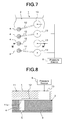
- FIGS. 7 and 8 show the fourth preferred embodiment of a liquid droplet ejecting apparatus 1 according to the present invention, which show a modified example of the liquid droplet ejecting apparatus 1 shown in FIGS. 1A, 1B and 2.
- FIG. 7 is an enlarged plan view showing a part of the liquid droplet ejecting apparatus 1
- FIG. 8 is a sectional view taken along line VIII-VIII of FIG. 7.
- an upper plate 11 is bonded to the top face of a substrate 2, and fine communication passages 12, one end of each of which is open to a corresponding one of holes 4 of the substrate 2, are formed on the bottom side (in a surface bonded to the substrate) 11a of the upper plate 11.
- the other end of each of the communication passages 12 formed in the upper plate 11 is open to a reservoir 13, which is formed in the upper plate 11, so as to establish a communication between the reservoir 13 and the corresponding one of the holes 4.
- a liquid supplied to the reservoir 13 passes through a corresponding one of the communication passages 12 to enter the corresponding one of the holes 4 to be fed into a corresponding one of small holes 5 of a photoresist film 3 due to capillarity. In this state, if the liquid in the reservoir 13 is pressurized by the pressure of the pressure source 6, a small amount of liquid is ejected from the corresponding one of small holes 5 of the photoresist film 3.
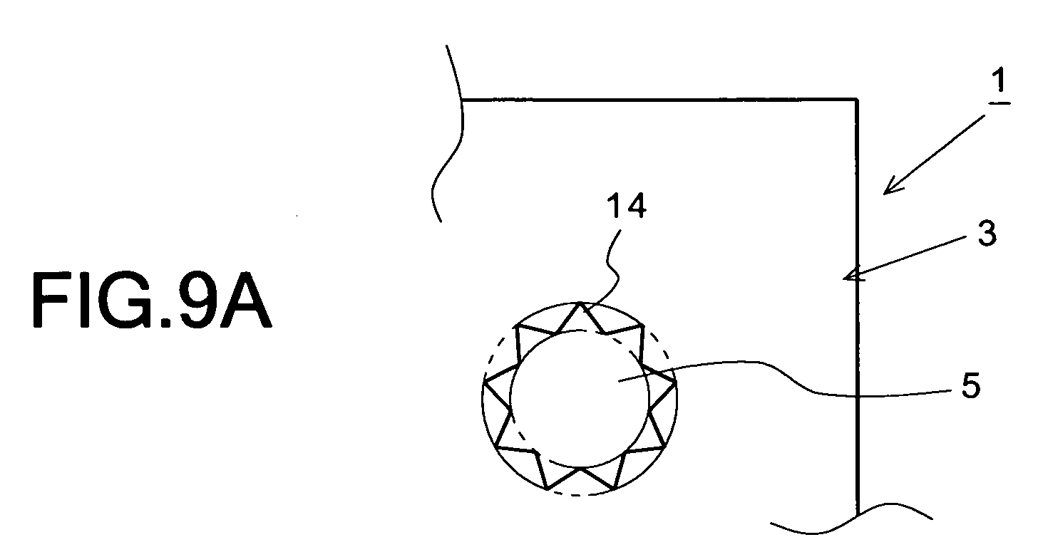
- FIGS. 9A through 9C show the shape of each of small holes 5 of a photoresist film 3 of the fifth preferred embodiment of a liquid droplet ejecting apparatus 1 according to the present invention, which show various modified examples of the shape of each of the small holes 5 shown in FIG. 1B. That is, the planar shape of each of the small holes 5 of FIG. 1B is a substantially circle.
- each of the small holes 5 in the fifth preferred embodiment shown in FIG. 9A has a plurality of radial grooves 14 arranged in circumferential directions so as to increase the surface area of the inner surface of each of the small holes 5. According to such a preferred embodiment, the surface tension in each of the small holes 5 increases to increase force acquiring a liquid in each of the small holes 5, so that it is possible to effectively prevent the liquid from being leaked out of the corresponding one of the small holes 5.
- each of the small holes 5 should not be limited to the shape shown in FIG. 9A.
- the inner surface of each of the small holes 5 may be regularly or irregularly roughened to increase the surface area of the inner surface thereof.
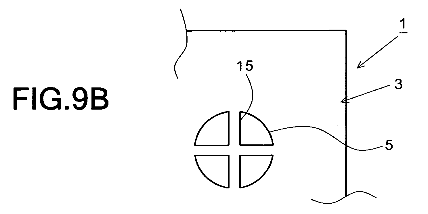
- each of small holes 5 having a substantially circular planar shape may be divided into four holes by a cross partition wall 15.
- each of small holes 5 having a substantially circular planar shape may be divided into a large number of holes by a lattice-shaped partition wall 16.
- the planar shape of each of small holes 5 may be triangular, rectangular or elliptical, although they are not shown.
- Each of small holes 5 may be a plurality of very small triangular holes, a plurality of very small rectangular holes, or a plurality of very small elliptical holes, although they are not shown.
- a liquid droplet ejecting apparatus can be used as an ink ejecting apparatus of an ink jet printer, as well as a spotting apparatus for applying a liquid droplet (a liquid sample) containing DNA fragments on a DNA chip or the like.
Landscapes
- Health & Medical Sciences (AREA)
- Clinical Laboratory Science (AREA)
- Chemical & Material Sciences (AREA)
- Chemical Kinetics & Catalysis (AREA)
- Nozzles (AREA)
- Particle Formation And Scattering Control In Inkjet Printers (AREA)
- Sampling And Sample Adjustment (AREA)
- Automatic Analysis And Handling Materials Therefor (AREA)
- Apparatus Associated With Microorganisms And Enzymes (AREA)
Abstract
Description
- The present invention generally relates to a liquid droplet ejecting apparatus and a method for producing the same. More specifically, the invention relates to a liquid droplet ejecting apparatus for ejecting a small amount of liquid droplet (e.g., an ink or a liquid containing substances derived from biosubstances, such as DNA), and a method for producing the same.
- In recent years, in order to examine the functions of genes or the like, the microarray technique capable of simultaneously examining thousands kinds to tens of thousands kinds of DNA fragments has been noticed particularly in the field of genome medical science.
- The microarray technique uses a DNA chip wherein various DNA fragments or the like (samples) are densely arranged on an inspection plate, such as a slide glass for microscope. In order to enhance the fabrication efficiency and determination precision of such a DNA chip, some of DNA chips are prepared by using a liquid droplet ejecting apparatus, which adapts the ink jet technique for ink jet printers, and by densely dropping a small amount of liquid sample onto an inspection plate.
- FIG. 10 shows an example of a liquid
droplet ejecting apparatus 30 used for preparing a DNA chip. Such a liquiddroplet ejecting apparatus 30 is designed to have a large number ofnozzles 31 having a small hole size for ejecting liquid droplets. Therefore, in the liquiddroplet ejecting apparatus 30, asubstrate 33 having relatively large-diameter holes 32a through 32d for supplying samples, and anozzle forming body 34 having small holes serving as thenozzles 31 are separately formed. That is, thesubstrate 33 is formed by stacking a plurality ofceramic plates 33a through 33d so as to align theholes 32a through 32d with each other, and then, the nozzle forming body 34 (of a plastic film, a stainless steel plate or the like) having the large number ofsmall holes 31 is stuck on the reverse of the substrate 33 (33a) while thesmall holes 31 are aligned with theholes 32a of the substrate 33 (see Japanese Patent Laid-Open No. 2003-75305). - However, if the
nozzle forming body 34 having the large number ofnozzles 31 are stuck on the reverse of theceramic plate 33a so that thenozzles 31 are aligned with theholes 32a of thesubstrate 33 as the conventional liquiddroplet ejecting apparatus 30 shown in FIG. 10, there is a problem in that fabrication operation takes a great deal of time to deteriorate productivity. In addition, if thesubstrate 33 is formed of a ceramic plate, there is a problem in that the price of materials is high, so that production costs are high. - In order to solve such problems, it is considered that the substrate and the nozzle forming body are integrally formed by injection molding, and the holes and small holes are simultaneously formed during the injection molding. However, in such a method for integrally forming the substrate and the nozzle forming body by the injection molding, it is difficult to arrange small hole forming pins in a cavity of a die in view of the structure of the die, if the hole size of the
nozzles 31 is intended to be hundreds micrometers or less. - It is therefore an object of the present invention to eliminate the aforementioned problems and to provide a liquid droplet ejecting apparatus capable of being effectively produced at low production costs.
- In order to accomplish the aforementioned and other objects, according to one aspect of the present invention, a liquid droplet ejecting apparatus comprises: a substrate having a through hole which extends in thickness directions to pass through the substrate; and a resist film formed on one side of the substrate to close one end of the through hole of the substrate, wherein the resist film has a small hole which faces the one end of the through hole to open the one end of the through hole to the atmosphere, and a droplet of a liquid is ejected from the small hole when a pressure is applied to the other end of the through hole after the liquid is injected into the through hole.
- According to another aspect of the present invention, a liquid droplet ejecting apparatus comprises: a substrate having a plurality of through holes, each of which extends in thickness directions to pass through the substrate; and a plurality of lid members of a resist film, each of the lid members being formed on one side of the substrate to close one end of a corresponding one of the through holes of the substrate, wherein each of the lid members has a small hole which faces the one end of the corresponding one of the through holes to open the one end of the corresponding one of the through holes to the atmosphere, and a droplet of a liquid is ejected from the small hole of a corresponding one of the lid members when a pressure is applied to the other end of a corresponding one of the through holes after the liquid is injected into the corresponding one of the through holes.
- According to a further aspect of the present invention, there is provided a method for producing a liquid droplet ejecting apparatus, the method comprising the steps of: forming a through hole in a substrate so that the through hole extends in thickness directions to pass through the substrate; forming a resist film on one side of the substrate to close one end of the through hole of the substrate; covering a portion of the resist film with a mask which has such a shape that a small hole is formed in the resist film to open the one end of the through hole to the atmosphere; exposing the resist film after the portion of the resist film is covered with the mask; and removing a portion of the resist film, which is not exposed, to form the small hole in the resist film.
- According to a still further aspect of the present invention, there is provided a method for producing a liquid droplet ejecting apparatus, the method comprising the steps of: forming a plurality of through holes in a substrate so that each of the through holes extends in thickness directions to pass through the substrate; forming a resist film on one side of the substrate to close one end of each of the through holes of the substrate; covering portions of the resist film with a mask which has such a shape that a plurality of lid members of the resist film are formed to close the one end of each of the through holes, respectively, and that a plurality of small holes are formed in the lid members to open the one end of each of the through holes to the atmosphere, respectively; exposing the resist film after the portions of the resist film are covered with the mask; and removing portions of the resist film, which are not exposed, to form the small holes in the lid members, respectively.
- In a liquid droplet ejecting apparatus according to the present invention, holes of a substrate serving as liquid supply ports are closed by a resist film in which a large number of small holes serving as nozzles are formed, so that the large number of small holes can be simultaneously formed with a developing solution. Therefore, it is possible to enhance the production efficiency, and it is possible to reduce the production costs.
- The present invention will be understood more fully from the detailed description given herebelow and from the accompanying drawings of the preferred embodiments of the invention. However, the drawings are not intended to imply limitation of the invention to a specific embodiment, but are for explanation and understanding only.
- In the drawings:
- FIG. 1A is a plan view schematically showing the first preferred embodiment of a liquid droplet ejecting apparatus according to the present invention;
- FIG. 1B is an enlarged plan view showing a part of FIG. 1A;
- FIG. 2 is a sectional view taken along line II-II of FIG. 1B;
- FIG. 3 is an enlarged plan view showing a part of the second preferred embodiment of a liquid droplet ejecting apparatus according to the present invention;
- FIG. 4 is a sectional view taken along line IV-IV of FIG. 3;
- FIG. 5 is a plan view showing a part of an example of a mask for covering a photoresist film;
- FIG. 6 is a sectional view showing a part of the third preferred embodiment of a liquid droplet ejecting apparatus according to the present invention, which corresponds to FIGS. 2 and 4;
- FIG. 7 is an enlarged plan view of a part of the fourthpreferred embodiment of a liquid droplet ejecting apparatus according to the present invention;
- FIG. 8 is a sectional view taken alone line VIII-VIII of FIG. 7;
- FIGS. 9A through 9C are plan views showing examples of small holes of the fifth preferred embodiment of a liquid droplet ejecting apparatus according to the present invention; and
- FIG. 10 is an enlarged sectional view of a part of a conventional liquid droplet ejecting apparatus.
-
- Referring now to the accompanying drawings, the preferred embodiments of the present invention will be described below in detail.
- FIGS. 1A, 1B and 2 show the first preferred embodiment of a liquid
droplet ejecting apparatus 1 according to the present invention. FIGS. 1A and 1B are plan views schematically showing the liquiddroplet ejecting apparatus 1, and FIG. 2 is a sectional view taken along line II-II of FIG. 1B. - As shown in these figures, the liquid
droplet ejecting apparatus 1 in this preferred embodiment comprises a flat-plate-shaped substrate 2, and aphotoresist film 3 formed on one side (bottom side in FIG. 2) 2a of thesubstrate 2. Thesubstrate 2 is formed of a plastic, glass, ceramic, silicon, metal or the like. Thesubstrate 2 has a rectangular planar shape, and a thickness of 1 to 2 mm. Thesubstrate 2 has a large number of throughholes 4 which extend in thickness directions to pass through thesubstrate 2. Each of theholes 4 of thesubstrate 2 has a diameter of about 300 µm which is a few times as large as that of each ofsmall holes 5 of thephotoresist film 3, which will be described later. Each of theholes 4 of thesubstrate 2 serves as a liquid supply port, into which a liquid, such as a sample containing DNA fragments or an ink, is designed to be injected. - The
photoresist film 3 is a super thick negative resist (e.g., a photoresist commercially available as TG-P series from Toyo Synthetic Industry Co., Ltd., or SU-8 fromMicrochemical Co., Ltd.) which is uniformly formed so as to have a thickness of about 100 µm. Thephotoresist film 3 has small holes (nozzles) 5 having a smaller diameter as that of each of theholes 4 of thesubstrate 2 so as to allow one end of each of theholes 4 to be open to the atmosphere. The diameter of each of thesmall holes 5 of thephotoresist film 3 is about 100 µm. Thus, the inner surface of each of thesmall holes 5 serving as nozzles can be selectively formed so as to be hydrophobic or hydrophilic in accordance with the material of the used resist or with a process for the resist film, which is carried out if necessary. - The other end of each of the
holes 4 of thesubstrate 2 is connected to a pressure source (e.g., an air pressure supply means comprising as a compressor and a valve) 6. If a pressure of thepressure source 6 is applied to a liquid injected into each of theholes 4 of thesubstrate 2, a small amount of liquid droplet is ejected from a corresponding one of thesmall holes 5 of thephotoresist film 3, so that the ejected liquid drops and adheres to the surface of a slide glass or copy paper for forming a DNA chip (not shown). Furthermore, if the pressure of thepressure source 6 is simultaneously applied to all of theholes 4 of thesubstrate 2, a small amount of liquid is simultaneously ejected from all of thesmall holes 5. Alternatively, if the pressure of thepressure source 6 is designed to be selectively applied to any one of the large number ofholes 4, the liquid can be ejected from only one of thesmall holes 5 corresponding to the one of theholes 4 to which the pressure of thepressure source 6 is applied. - A method for producing the liquid
droplet ejecting apparatus 1 in this preferred embodiment will be described below. - First, a large number of
holes 4 are formed in asubstrate 2 by injection molding or machining (a first step). Then, a photoresist is formed on oneside 2a of thesubstrate 2 by spin coating so as to have a thickness of about 100 µm, and after the spin coating of aphotoresist film 3 is completed, thephotoresist film 3 is dried at 100°C for about five minutes (a second step). Thereafter, the surface of thephotoresist film 3 is covered with a mask (not shown) formed so as to shade portions in whichsmall holes 5 are to be formed (a third step). Then, the surface of thephotoresist film 3 is exposed (a fourth step). After this exposure is completed, the mask is removed from the surface of thephotoresist film 3, and thephotoresist film 3 is heated at 100°C for five to ten minutes. Then, thephotoresist film 3 is dipped in a developing solution to remove non-exposed portions of the photoresist film 3 (portions shaded with the mask). Thus, the large number of small holes (nozzles) 5 having a diameter of about 100 µm can be simultaneously formed. - In the liquid
droplet ejecting apparatus 1 in this preferred embodiment as described above, theholes 4 of thesubstrate 2 serving as the liquid supply ports are closed with thephotoresist films 3, and thesmall holes 5 serving as the nozzles are formed in thephotoresist films 3, so that the large number ofsmall holes 5 can be simultaneously formed with the developing solution. Therefore, it is possible to enhance the production efficiency, and it is possible to reduce the production costs. - While various numerical values, producing conditions and so forth in this preferred embodiment have been disclosed as examples in order to facilitate better understanding of the present invention, it should not be limited thereto, but the optimum dimensions, producing conditions and so forth may be set in accordance with design conditions and so forth.
- While the
photoresist film 3 has been described as an example of a resist film in the above described preferred embodiment, the present invention should not be limited thereto, but a far ultraviolet radiation resist film, an X-ray resist film or an electron beam resist film may be substituted for thephotoresist film 3. In addition, while thephotoresist film 3 has been made of the high polymer resist as an example in the above described preferred embodiment, it may be made of an inorganic resist. Moreover, while the negative resist has bee used as an example in the above descried preferred embodiment, a positive resist may be used. - The thickness of the
photoresist film 3 should not be limited to 100 µm which has been described as an example in the above described preferred embodiment, but the optimum numerical value may be selected in the range of 1 to 1000 µm. - The diameter of each of the
small holes 5 should not be limited to 100 µm which has been described as an example in the above described preferred embodiment, but the optimum numerical value may be selected in the range of 1 to 1000 µm (preferably in the range of 10 to 500 µm). - FIGS. 3 and 4 show the second preferred embodiment of a liquid droplet ejecting apparatus according to the present invention, which show a modified example of the above described first preferred embodiment. FIG. 3 is an enlarged plan view of a part of the second preferred embodiment of a liquid droplet ejecting apparatus according to the present invention, and FIG. 4 is a sectional view taken along line IV-IV of FIG. 3.
- According to this preferred embodiment, portions of a
photoresist film 3 corresponding tosmall holes 5 are removed, andperipheral portions 7 of thephotoresist film 3 except for portions near the opening edges ofholes 4 of asubstrate 2 are removed. As a result, in FIG. 4, disk-shapedphotoresist films 3, each of which has asmall hole 5 at its center, are separately fixed to thebottom side 2a of thesubstrate 2 so as to correspond to theholes 4. Each of thephotoresist films 3 serves as a lid member for closing one end (thebottom side 2a) of a corresponding one of theholes 4 of thesubstrate 2. Each of thesmall holes 5 decreases the opening area of the one end (on thebottom side 2a) of the corresponding one of theholes 4, and allows the one end of the corresponding one of theholes 4 to be open to the atmosphere. - With this construction, the
photoresist films 3 are separately fixed to thebottom side 2a of thesubstrate 2. Therefore, even if a liquid adheres to a portion near the opening edge of one of thesmall holes 5, the liquid does not reach adjacent one of thesmall holes 5 via the surface of thephotoresist films 3, so that it is possible to effectively prevent the liquid from being mixed with a liquid in the adjacent one of thesmall holes 5. Therefore, according to this preferred embodiment, in addition to the advantageous effects of the above described first preferred embodiment, it is possible to prevent liquids, which are ejected from adjacent two of thesmall holes 5, from being mixed with each other, and it is possible to more precisely eject liquid droplets. - A method for producing the liquid
droplet ejecting apparatus 1 in this preferred embodiment will be described below. - First, a large number of
holes 4 are formed in asubstrate 2 by injection molding or machining (a first step). Then, a photoresist is formed on oneside 2a of thesubstrate 2 by spin coating so as to have a thickness of about 100 µm, and after the spin coating of aphotoresist film 3 is completed, thephotoresist film 3 is dried at 100°C for about five minutes (a second step). Thereafter, as shown in FIG. 5, the surface of thephotoresist film 3 is covered with amask 10 formed so as to shade portions (portions 8 shown by slanting lines), in whichsmall holes 5 are to be formed, and peripheral portions (portions 7 shown by slanting lines) expect for portions near the opening edges of theholes 4 of the substrate 2 (a third step). Then, the surface of thephotoresist film 3 is exposed (a fourth step). After this exposure is completed, themask 10 is removed from the surface of thephotoresist film 3, and thephotoresist film 3 is heated at 100°C for five to ten minutes. Then, thephotoresist film 3 is dipped in a developing solution to remove non-exposed portions of the photoresist film 3 (portions photoresist films 3, each of which has asmall hole 5 at its center, are simultaneously formed so as to correspond to theholes 4 of thesubstrate 2 and so as to be isolated from each other as floating islands. - FIG. 6 is a sectional view showing a part of the third preferred embodiment of a liquid
droplet ejecting apparatus 1 according to the present invention, which corresponds to FIGS. 2 and 4. - In the preferred embodiment shown in FIG. 6, truncated
conical holes 4 are formed in asubstrate 2 so that the diameter of each of theholes 4 increases as a distance from a corresponding one ofsmall holes 5 of aphotoresist film 3 increases. Thus, the upper opening portion of each of theholes 4 is as large as possible, so that the volume of each of theholes 4 is greater than that of each of the substantiallycylindrical holes 4 shown in FIGS. 2 and 4. - FIGS. 7 and 8 show the fourth preferred embodiment of a liquid
droplet ejecting apparatus 1 according to the present invention, which show a modified example of the liquiddroplet ejecting apparatus 1 shown in FIGS. 1A, 1B and 2. FIG. 7 is an enlarged plan view showing a part of the liquiddroplet ejecting apparatus 1, and FIG. 8 is a sectional view taken along line VIII-VIII of FIG. 7. - As shown in these figures, in this preferred embodiment, an
upper plate 11 is bonded to the top face of asubstrate 2, andfine communication passages 12, one end of each of which is open to a corresponding one ofholes 4 of thesubstrate 2, are formed on the bottom side (in a surface bonded to the substrate) 11a of theupper plate 11. The other end of each of thecommunication passages 12 formed in theupper plate 11 is open to areservoir 13, which is formed in theupper plate 11, so as to establish a communication between thereservoir 13 and the corresponding one of theholes 4. A liquid supplied to thereservoir 13 passes through a corresponding one of thecommunication passages 12 to enter the corresponding one of theholes 4 to be fed into a corresponding one ofsmall holes 5 of aphotoresist film 3 due to capillarity. In this state, if the liquid in thereservoir 13 is pressurized by the pressure of thepressure source 6, a small amount of liquid is ejected from the corresponding one ofsmall holes 5 of thephotoresist film 3. - According to such a preferred embodiment, in addition to the same advantageous effects as those of the liquid
droplet ejecting apparatus 1 shown in FIGS. 1A, 1B and 2, it is possible to decrease the diameter of each of theholes 4 of thesubstrate 2, and it is possible to enhance the density of arrangement of thesmall holes 5 of thephotoresist film 3. - FIGS. 9A through 9C show the shape of each of
small holes 5 of aphotoresist film 3 of the fifth preferred embodiment of a liquiddroplet ejecting apparatus 1 according to the present invention, which show various modified examples of the shape of each of thesmall holes 5 shown in FIG. 1B. That is, the planar shape of each of thesmall holes 5 of FIG. 1B is a substantially circle. On the other hand, each of thesmall holes 5 in the fifth preferred embodiment shown in FIG. 9A has a plurality ofradial grooves 14 arranged in circumferential directions so as to increase the surface area of the inner surface of each of thesmall holes 5. According to such a preferred embodiment, the surface tension in each of thesmall holes 5 increases to increase force acquiring a liquid in each of thesmall holes 5, so that it is possible to effectively prevent the liquid from being leaked out of the corresponding one of thesmall holes 5. - Furthermore, the shape of each of the
small holes 5 should not be limited to the shape shown in FIG. 9A. For example, the inner surface of each of thesmall holes 5 may be regularly or irregularly roughened to increase the surface area of the inner surface thereof. Alternatively, as shown in FIG. 9B, each ofsmall holes 5 having a substantially circular planar shape may be divided into four holes by across partition wall 15. As shown in FIG. 9C, each ofsmall holes 5 having a substantially circular planar shape may be divided into a large number of holes by a lattice-shapedpartition wall 16. The planar shape of each ofsmall holes 5 may be triangular, rectangular or elliptical, although they are not shown. Each ofsmall holes 5 may be a plurality of very small triangular holes, a plurality of very small rectangular holes, or a plurality of very small elliptical holes, although they are not shown. - A liquid droplet ejecting apparatus according to the present invention can be used as an ink ejecting apparatus of an ink jet printer, as well as a spotting apparatus for applying a liquid droplet (a liquid sample) containing DNA fragments on a DNA chip or the like.
Claims (4)
- A liquid droplet ejecting apparatus comprising:a substrate having a through hole which extends in thickness directions to pass through the substrate; anda resist film formed on one side of said substrate to close one end of said through hole of said substrate,
wherein said resist film has a small hole which faces said one end of said through hole to open said one end of said through hole to the atmosphere, anda droplet of a liquid is ejected from said small hole when a pressure is applied to the other end of said through hole after said liquid is injected into said through hole. - A liquid droplet ejecting apparatus comprising:a substrate having a plurality of through holes, each of which extends in thickness directions to pass through the substrate; anda plurality of lid members of a resist film, each of said lid members being formed on one side of said substrate to close one end of a corresponding one of said through holes of said substrate,
wherein each of said lid members has a small hole which faces said one end of said corresponding one of said through holes to open said one end of said corresponding one of said through holes to the atmosphere, anda droplet of a liquid is ejected from said small hole of a corresponding one of said lid members when a pressure is applied to the other end of a corresponding one of said through holes after said liquid is injected into said corresponding one of said through holes. - A method for producing a liquid droplet ejecting apparatus, said method comprising the steps of:forming a through hole in a substrate so that the through hole extends in thickness directions to pass through the substrate;forming a resist film on one side of said substrate to close one end of said through hole of said substrate;covering a portion of said resist film with a mask which has such a shape that a small hole is formed in said resist film to open said one end of said through hole to the atmosphere;exposing said resist film after said portion of said resist film is covered with said mask; andremoving a portion of said resist film, which is not exposed, to form said small hole in said resist film.
- A method for producing a liquid droplet ejecting apparatus, said method comprising the steps of:forming a plurality of through holes in a substrate so that each of the through holes extends in thickness directions to pass through the substrate;forming a resist film on one side of said substrate to close one end of each of said through holes of said substrate;covering portions of said resist film with a mask which has such a shape that a plurality of lid members of said resist film are formed to close said one end of each of said through holes, respectively, and that a plurality of small holes are formed in said lid members to open said one end of each of said through holes to the atmosphere, respectively;exposing said resist film after said portions of said resist film are covered with said mask; andremoving portions of said resist film, which are not exposed, to form said small holes in said lidmembers, respectively.
Applications Claiming Priority (2)
| Application Number | Priority Date | Filing Date | Title |
|---|---|---|---|
| JP2004057010 | 2004-03-02 | ||
| JP2004057010A JP2005249436A (en) | 2004-03-02 | 2004-03-02 | Droplet discharge device and manufacturing method of droplet discharge device |
Publications (2)
| Publication Number | Publication Date |
|---|---|
| EP1570991A2 true EP1570991A2 (en) | 2005-09-07 |
| EP1570991A3 EP1570991A3 (en) | 2006-10-18 |
Family
ID=34747611
Family Applications (1)
| Application Number | Title | Priority Date | Filing Date |
|---|---|---|---|
| EP05004352A Withdrawn EP1570991A3 (en) | 2004-03-02 | 2005-02-28 | Liquid droplet ejecting apparatus und method for producing same |
Country Status (3)
| Country | Link |
|---|---|
| US (1) | US20050195245A1 (en) |
| EP (1) | EP1570991A3 (en) |
| JP (1) | JP2005249436A (en) |
Families Citing this family (4)
| Publication number | Priority date | Publication date | Assignee | Title |
|---|---|---|---|---|
| JP4639340B2 (en) * | 2005-03-30 | 2011-02-23 | 国立大学法人名古屋大学 | Bio-organism production method and culture vessel |
| US8263414B2 (en) | 2005-05-23 | 2012-09-11 | Siemens Healthcare Diagnostics Inc. | Dispensing of a diagnostic liquid onto a diagnostic reagent |
| GB0606685D0 (en) | 2006-04-03 | 2006-05-10 | Xaar Technology Ltd | Droplet Deposition Apparatus |
| WO2008117716A1 (en) | 2007-03-28 | 2008-10-02 | Konica Minolta Holdings, Inc. | Liquid ejection head and liquid ejector |
Citations (1)
| Publication number | Priority date | Publication date | Assignee | Title |
|---|---|---|---|---|
| JP2003075305A (en) | 2001-08-31 | 2003-03-12 | Ngk Insulators Ltd | Dripping apparatus |
Family Cites Families (8)
| Publication number | Priority date | Publication date | Assignee | Title |
|---|---|---|---|---|
| US4558333A (en) * | 1981-07-09 | 1985-12-10 | Canon Kabushiki Kaisha | Liquid jet recording head |
| US4961821A (en) * | 1989-11-22 | 1990-10-09 | Xerox Corporation | Ode through holes and butt edges without edge dicing |
| US5685491A (en) * | 1995-01-11 | 1997-11-11 | Amtx, Inc. | Electroformed multilayer spray director and a process for the preparation thereof |
| US5790151A (en) * | 1996-03-27 | 1998-08-04 | Imaging Technology International Corp. | Ink jet printhead and method of making |
| US6299288B1 (en) * | 1997-02-21 | 2001-10-09 | Independent Ink, Inc. | Method and apparatus for variably controlling size of print head orifice and ink droplet |
| US6569343B1 (en) * | 1999-07-02 | 2003-05-27 | Canon Kabushiki Kaisha | Method for producing liquid discharge head, liquid discharge head, head cartridge, liquid discharging recording apparatus, method for producing silicon plate and silicon plate |
| SE0003293D0 (en) * | 2000-09-15 | 2000-09-15 | Aamic Ab | Dispensing nozzle |
| KR100406943B1 (en) * | 2000-10-28 | 2003-11-21 | 삼성전자주식회사 | Printhead and fabrication method thereof |
-
2004
- 2004-03-02 JP JP2004057010A patent/JP2005249436A/en active Pending
-
2005
- 2005-02-25 US US11/065,945 patent/US20050195245A1/en not_active Abandoned
- 2005-02-28 EP EP05004352A patent/EP1570991A3/en not_active Withdrawn
Patent Citations (1)
| Publication number | Priority date | Publication date | Assignee | Title |
|---|---|---|---|---|
| JP2003075305A (en) | 2001-08-31 | 2003-03-12 | Ngk Insulators Ltd | Dripping apparatus |
Also Published As
| Publication number | Publication date |
|---|---|
| EP1570991A3 (en) | 2006-10-18 |
| US20050195245A1 (en) | 2005-09-08 |
| JP2005249436A (en) | 2005-09-15 |
Similar Documents
| Publication | Publication Date | Title |
|---|---|---|
| US11097269B2 (en) | Microfluidic device and sample analysis method | |
| US10974247B2 (en) | Nanoliter array loading | |
| DE60033218T2 (en) | A method of manufacturing a liquid ejection head, liquid ejection head, head cartridge, liquid ejection device, silicon substrate manufacturing method, and silicon plate produced thereby | |
| CN101495318B (en) | Fluid ejection devices and methods of fabrication | |
| US8192637B2 (en) | Method and apparatus for imprinting microstructure and stamper therefor | |
| JP2003505679A (en) | Method and apparatus for transferring small liquid samples | |
| US20130083126A1 (en) | Liquid ejection device with planarized nozzle plate | |
| CN1371302A (en) | Apparatus and method for adding many microdroplets to a substrate | |
| US20050195245A1 (en) | Liquid droplet ejecting apparatus and method for producing same | |
| JP7612877B2 (en) | Electrohydrodynamic printhead with ink pinning - Patent Application 20070123633 | |
| JP2002204945A (en) | Micropipet, dispenser, and method for producing biochip | |
| US20050287044A1 (en) | Test apparatus and method | |
| JP2006281715A (en) | Liquid discharge head and manufacturing method thereof | |
| KR102218428B1 (en) | Micropatterning method via microcontact printing and degas-driven flow guided patterning, and self-assembled monolayer prepared thereby | |
| JP2017064930A (en) | Method for manufacturing liquid discharge head | |
| JP4834974B2 (en) | Method for forming black matrix of color filter and method for forming color filter | |
| JP2012521543A (en) | Analytical strip and method for producing the same | |
| KR20030083616A (en) | Liquid discharge apparatus, printer head, and method for making liquid discharge apparatus | |
| US6684504B2 (en) | Method of manufacturing an imageable support matrix for printhead nozzle plates | |
| WO2020095849A1 (en) | Cell culturing chip and production method therefor | |
| CN100522620C (en) | Liquid discharge head and manufacturing method of the same | |
| JP2005279553A (en) | LIQUID QUANTITY DISCHARGE DEVICE, ITS MANUFACTURING METHOD, LIQUID QUANTITY DISCHARGE METHOD, AND PARTICLE CONSTANT DISCHARGE METHOD | |
| JP4407161B2 (en) | Pattern forming apparatus and method | |
| CN121347804A (en) | A system for forming a microarray of analyte measurement regions on a solid support | |
| Tseng et al. | Characterization of simultaneous protein microarray formation by discrete micro stamper on surfaces of different wettabilities |
Legal Events
| Date | Code | Title | Description |
|---|---|---|---|
| PUAI | Public reference made under article 153(3) epc to a published international application that has entered the european phase |
Free format text: ORIGINAL CODE: 0009012 |
|
| AK | Designated contracting states |
Kind code of ref document: A2 Designated state(s): AT BE BG CH CY CZ DE DK EE ES FI FR GB GR HU IE IS IT LI LT LU MC NL PL PT RO SE SI SK TR |
|
| AX | Request for extension of the european patent |
Extension state: AL BA HR LV MK YU |
|
| PUAL | Search report despatched |
Free format text: ORIGINAL CODE: 0009013 |
|
| AK | Designated contracting states |
Kind code of ref document: A3 Designated state(s): AT BE BG CH CY CZ DE DK EE ES FI FR GB GR HU IE IS IT LI LT LU MC NL PL PT RO SE SI SK TR |
|
| AX | Request for extension of the european patent |
Extension state: AL BA HR LV MK YU |
|
| RIC1 | Information provided on ipc code assigned before grant |
Ipc: G01N 35/10 20060101ALI20060908BHEP Ipc: B01J 19/00 20060101ALI20060908BHEP Ipc: B01L 3/02 20060101ALI20060908BHEP Ipc: B41J 2/16 20060101ALI20060908BHEP Ipc: B41J 2/14 20060101AFI20050627BHEP |
|
| AKX | Designation fees paid | ||
| STAA | Information on the status of an ep patent application or granted ep patent |
Free format text: STATUS: THE APPLICATION IS DEEMED TO BE WITHDRAWN |
|
| 18D | Application deemed to be withdrawn |
Effective date: 20070419 |
|
| REG | Reference to a national code |
Ref country code: DE Ref legal event code: 8566 |