EP1570867A2 - Electric vaporiser of fragrances or insecticides, with evaporation intensity adjustment function - Google Patents
Electric vaporiser of fragrances or insecticides, with evaporation intensity adjustment function Download PDFInfo
- Publication number
- EP1570867A2 EP1570867A2 EP05101664A EP05101664A EP1570867A2 EP 1570867 A2 EP1570867 A2 EP 1570867A2 EP 05101664 A EP05101664 A EP 05101664A EP 05101664 A EP05101664 A EP 05101664A EP 1570867 A2 EP1570867 A2 EP 1570867A2
- Authority
- EP
- European Patent Office
- Prior art keywords
- vaporiser
- electric
- drawer
- heating device
- porous element
- Prior art date
- Legal status (The legal status is an assumption and is not a legal conclusion. Google has not performed a legal analysis and makes no representation as to the accuracy of the status listed.)
- Granted
Links
Images

Classifications
-
- A—HUMAN NECESSITIES
- A61—MEDICAL OR VETERINARY SCIENCE; HYGIENE
- A61L—METHODS OR APPARATUS FOR STERILISING MATERIALS OR OBJECTS IN GENERAL; DISINFECTION, STERILISATION OR DEODORISATION OF AIR; CHEMICAL ASPECTS OF BANDAGES, DRESSINGS, ABSORBENT PADS OR SURGICAL ARTICLES; MATERIALS FOR BANDAGES, DRESSINGS, ABSORBENT PADS OR SURGICAL ARTICLES
- A61L9/00—Disinfection, sterilisation or deodorisation of air
- A61L9/015—Disinfection, sterilisation or deodorisation of air using gaseous or vaporous substances, e.g. ozone
- A61L9/02—Disinfection, sterilisation or deodorisation of air using gaseous or vaporous substances, e.g. ozone using substances evaporated in the air by heating or combustion
- A61L9/03—Apparatus therefor
- A61L9/037—Apparatus therefor comprising a wick
-
- A—HUMAN NECESSITIES
- A01—AGRICULTURE; FORESTRY; ANIMAL HUSBANDRY; HUNTING; TRAPPING; FISHING
- A01M—CATCHING, TRAPPING OR SCARING OF ANIMALS; APPARATUS FOR THE DESTRUCTION OF NOXIOUS ANIMALS OR NOXIOUS PLANTS
- A01M1/00—Stationary means for catching or killing insects
- A01M1/20—Poisoning, narcotising, or burning insects
- A01M1/2022—Poisoning or narcotising insects by vaporising an insecticide
- A01M1/2061—Poisoning or narcotising insects by vaporising an insecticide using a heat source
- A01M1/2077—Poisoning or narcotising insects by vaporising an insecticide using a heat source using an electrical resistance as heat source
Definitions
- the present invention relates to an electric vaporiser of fragrances or insecticides, wherein it is possible to adjust the evaporation intensity of the active substance between a minimum value and a maximum value, by varying the flow of the heat transmitted to the porous support impregnated with said active substance.
- the present invention relates to an electric vaporiser of fragrances or insecticides in liquid formulations, wherein the active substance is contained in an airtight bottle.
- a bottle houses a porous wick, which partly protrudes from the bottle neck passing in the proximity of an evaporation area of the vaporiser.
- the vaporiser in fact comprises an electric heating device - normally in the shape of an electric resistance or of a PTC - and by the expression "evaporation area" the area is in fact intended wherein the heat flow generated by said electric heating device spreads over the wick determining the evaporation of the active substance contained therein and thereby the desired operation of the vaporiser, while fresh active substance is continuously withdrawn from the bottle into the wick due to the capillary effect.
- vaporisers In the field of domestic electric vaporisers used with liquid formulations, vaporisers are already known which allow to adjust the evaporation intensity of the active substance by modifying the mutual position of the heating device and of the wick.
- the heating device is fixed and the bottle, with its wick, is shifted along the axis thereof by a mechanical device, for example of the screw/nut type or more simply of the friction type, in order to increase or decrease the evaporation area, i.e. the area where wick and heating device overlap; a device of this type is described for example in EP-A-0942648.
- a solution of this type has the advantage of a simplified construction of the heating device and of the corresponding electrical connections, indeed due to the fact that such device is fixed; however, vaporisers using a screw/nut mechanism for axially shifting the bottle, have the drawback - due to the high number of components they consist of and to the consequently high cost of the fitting operations which need to be carried out, at least partly, manually - of a high manufacturing cost; for the friction-type ones, which are instead of a simpler and cheaper construction, the main drawback lies in their awkwardness during use and in the poor stability of the desired adjustment position in case of involuntary manipulations.
- the heating device is integral with the plug and rotating therewith, as described for example in EP-A-0943344.
- the plug body is further manufactured in such a way, with a screw/nut or eccentric device, as to allow axial or lateral shifting of the body itself, and consequently of the heating device, with respect to the wick, in the different possible positions taken up by the plug.
- a third and last vaporiser category it is instead the heating device which is movable, and it is driven closer to or further apart from the wick of the bottle containing the liquid active solution, thanks to a mechanic device of the screw/nut type, so as to increase or decrease the heat flow which spreads over the wick itself.
- a mechanic device of the screw/nut type so as to increase or decrease the heat flow which spreads over the wick itself.
- Such a device is disclosed for example in ES-U-1015255.
- the main drawbacks of this type of vaporisers lie, on one hand and as already seen above with reference to vaporisers of the first category, on the high manufacturing cost of the mechanical screw/nut device and, on the other hand, on the safety and duration of the electrical connections between the plug and the heating device, which connections are necessarily subject to continuous movement during adjustment operations on the vaporiser.
- the object of the present invention is precisely to provide an electric vaporiser of insecticides or fragrances belonging to the third category described above, wherein, however, optimal and continuous adjustment of the flow of the evaporated active substance can be obtained, which flow is comprised between a minimum flow and a maximum flow, with no need to employ complex mechanical systems of the screw/nut type and further preventing the inevitable shiftings of the electrical connections of the heating device during adjustment operations of the evaporation flow from compromising the safety and duration of said connections.
- Another object of the present invention is further to provide a vaporiser of the aforementioned type wherein the evaporation area contains no moving components located between the wick and the heating device, which components may varyingly alter or shield the heat flow in the different mutual positions between the wick and the heating device, so that such heat flow continuously changes exclusively according to the distance between the wick and the heating device.
- fig. 1 is an elevation front view of the vaporiser according to the present invention in an intermediate adjustment position
- fig. 2 is a cross-section view of the vaporiser of fig. 1, along line II - II of the same drawing;
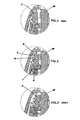
- fig. 3 is an enlarged-scale view of the detail encircled in fig. 2;
- fig. 3min is a similar view to fig. 3, wherein the vaporiser is adjusted on minimum flow;
- fig. 3max is a similar view to fig. 3, wherein the vaporiser is adjusted on maximum flow;
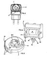
- fig. 4 is a bottom plan view of the vaporiser of fig. 1, with no bottle containing the active substance;
- fig. 5 is a perspective view of the inner technical body of the vaporiser, plug side;
- fig. 6 is a perspective view in an enlarged scale of the vaporiser adjustment disc
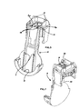
- fig. 7 is a perspective view of the inner technical body of the vaporiser, bottle side, with the adjustment disc mounted on the same;
- fig. 8 is a perspective view, in an enlarged scale, of the sliding drawer housing the electric heating device.
- Fig. 1 shows an external view of the vaporiser of the present invention in a fully assembled condition, wherein it is possible to see the edge of an adjustment disc 1 slightly protruding from the contour of the vaporiser, from the bottle side view F. Adjustment of the evaporation intensity of the active substance occurs by rotating disc 1 between a position of minimum heat flow and one of maximum heat flow. Thanks to the special internal structure adopted - as will be clear in the following - the adjustment is such as to obtain a continuous variation of the evaporation intensity between the positions of minimum and maximum flow, thereby allowing correct and steady operation of the vaporiser with any desired intermediate evaporation intensity.
- Such structure comprises a single inner technical body 2, onto which the different components of the vaporiser are assembled, more specifically: adjustment disc 1, a slidable drawer 3 housing an electric heating device R, a casing top C and a rotary plug S.
- adjustment disc 1 Upon use, bottle F containing the active substance is finally inserted in the vaporiser, within which bottle a wick W is housed which crosses the whole height of bottle F and comes out of the neck of the same by a portion sufficient to position itself opposite the drawer 3 containing the heating device, i.e. precisely in the evaporation area of the vaporiser.
- evaporation area is shown in greater detail in figs. 3, wherein it is possible to see how, due to the adjustment, the slidable drawer 3 containing heating device R shifts parallel to itself in a direction perpendicular to the axis of wick W, between a position of longest distance from the wick W and hence of minimum evaporation intensity (fig. 3min - wherein the outer wall of drawer 3 is at a distance of about 3 mm from the wick) and a position wherein the outer wall of drawer 3 is virtually touching the wick (fig. 3max) and the vaporiser is hence capable of providing maximum evaporation intensity of the active substance.
- the evaporation area contains no mobile component, nor any other element, fixed or mobile, which can varyingly shield or alter the heat flow coming from heating device R, in all the different positions in which drawer 3 can be arranged.
- the evaporation intensity of the active substance can be adjusted with the same continuity and effectiveness.
- FIG. 5 Overall and perspective views of the inner technical body 2 only of the vaporiser are shown in figs. 5 and 7.
- the technical body 2 is shown from the plug side; therein the lower circular half-seat 6 for rotary plug S, a double plug-in seat 7 for top C, and a pair of threaded holes 8 for fixing said top to body 2 are clearly visible.
- a hole 9 for housing adjustment disc 1 and, next thereto, a pair of ribs 10 which act as a guiding track of drawer 3 of heating device R are further formed.
- Adjustment disc 1 is shown in an enlarged scale in fig. 6, where it can be appreciated, in addition to the already-described curved eyelet 5, that the disc side surface - in the area thereof protruding from the casing top C of the vaporiser through a suitable window obtained therein - has quite a pronounced knurling 13, for a good grip by the user, inside which a raised ratchet 14 is formed, which acts as an indicator of the position of disc 1 with respect to an external scale of reference drawn on top C.
- Disc 1 finally has a central hole, for housing wick W, around which multiple raised circle sectors are found.
- Part thereof, and specifically the three sectors 15f, are fixed and form the rotation reference for disc 1 on the edge of hole 9 of technical body 2, within which said sectors are fitted with slack; another part of the sectors instead, and specifically the three sectors 15e arranged alternately to sectors 15f, is capable of a modest elastic excursion in a radial direction, and has a free hook-shaped end, so that by pushing disc 1 against wall 2p of the body 2 wherein hole 9 is formed, the hook-shaped elastic elements 15e enter said hole by elastically bending and then return into their original position snapping up and enclosing the edge of hole 9 inside their hook area, thereby ensuring a steady positioning of adjustment disc 1.
- the technical body 2 with the adjustment disc mounted on the same is shown in fig.
- fig. 8 shows the slidable drawer 3 of heating device R, essentially consisting of a parallelepipedal block centrally provided with a recess 17 for housing a heating device R, such as a resistance or a PTC.
- the drawer 3 is further provided, in the bottom part thereof, with the already-described protruding pin 4.
- Pin 4 has a cylindro-conical annular rib 18 which separates a central portion 4r thereof, intended to slidingly engage with the rectilinear eyelet 5 of body 2 of the vaporiser, from an end portion 4c intended instead to slidingly engage with the curved eyelet 5 of adjustment disc 1.
- annular rib 18 allows on the one hand to easily insert the same into rectilinear eyelet 11, due to the elastic deformation of the latter, thanks to the draft represented by the tapered part of the rib and, on the other hand, to form a steady retention with the cylindrical portion thereof in order to maintain drawer 3 steadily positioned in a vertical direction with respect to body 2, during shiftings of the same in a horizontal direction.
- the side walls of drawer 3 extend downwards, beyond the bottom plane of the drawer, forming two parallel abutting portions 19, apt to cooperate externally with the guiding track formed by ribs 10 provided on body 2.
- the vaporiser of the present invention has thereby achieved all the objects of the present invention. It has in fact an extremely simple and compact mechanical structure, both in terms of construction of the single components, and in terms of mounting the same, which mounting can hence be easily automated. Moreover, no element, fixed or mobile, is present in the evaporation area, between drawer 3 and wick W, while drawer 3 always moves perfectly parallel to itself, so that the variation of the heat flow spreading over the wick only depends on the distance between the wick W and the resistance R, and varies continuously therewith. Furthermore, thanks to the precision of the system moving drawer 3, the movement of the same repeats itself identically at each adjustment operation, so that the adjustment effect is optimally repeatable over time. Finally, the electrical connections of the resistance are arranged so as to guarantee their longer duration and safety despite the movement which is imparted to the same by the adjustment movement of drawer 3.
Abstract
Description
Claims (14)
- Electric vaporiser of a fragranced or insecticidal active substance with adjustment of the evaporation intensity, of the type comprising a support technical body (2), a porous element (W) impregnated with said active substance and an electric heating device (R) located in the proximity of said porous element (W) in order to determine the evaporation of the active substance in an evaporation area, said porous element (W) and said electric heating device (R) being fixed to said support body (2), characterised in that said electric heating device (R) is movable in a direction substantially perpendicular to said porous element (W) between a position of maximum evaporation intensity, near or adjacent to the porous element (W), and a position of minimum evaporation intensity, far from the porous element (W), and in that the control mechanism which causes the shifting of the electric device (R) is located outside said evaporation area.
- Electric vaporiser as in claim 1), wherein said porous element is the protruding portion of a wick (W) sunk in a bottle (F) containing said active substance in a liquid formulation.
- Electric vaporiser as in claim 2), wherein said electric device (R) is housed in a drawer (3) which is movable between said positions.
- Electric vaporiser as in claim 3), wherein said drawer is slidable along rectilinear ribs (11) formed in the vaporiser body (2) with which parallel abutting portions (19) engage, the movement of the drawer (3) being driven by the coupling between a pin (4) protruding from said drawer (3) and a variable-radius guiding cam (5) formed in an adjustment disc (1).
- Electric vaporiser as in claim 4), wherein said pin (4) cooperates with said variable-radius guiding cam (5) at an end portion (4c) thereof, while being guided by a mid-portion (4r) thereof into a rectilinear eyelet (11) formed in the vaporiser body (2), which is parallel to said ribs (10).
- Electric vaporiser as in claim 5), wherein said mid-portion (4c) and end-portion (4r) of the pin (4) are separated by an annular cylindro-conical rib (18) which serves firstly as a draft and secondly as a retention in respect of said rectilinear eyelet (11).
- Electric vaporiser as in any one of the claims 4) to 6), wherein said adjustment disc (1) is coaxial to said wick (W) and has a hole for the same to pass through.
- Electric vaporiser as in claim 7), wherein said adjustment disc (1) is fixed to said vaporiser body (2) at the mouth of the bottle (F).
- Electric vaporiser as in claim 8), wherein said adjustment disc (1) has, around the through-hole for the wick (W), a series of raised circle sectors (15) for the freely rotatable coupling with a corresponding hole (9) formed in the vaporiser body (2), on the same plane and horizontal wall (2p) wherein the rectilinear ribs (10) and eyelet (11) for guiding the drawer (3) are formed.
- Electric vaporiser as in claims 4) to 9), wherein the drawer (3) containing the electrical device (R), and the adjustment disc (1), are mounted on opposite sides in respect of said plane and horizontal wall (2p) of the vaporiser body (2), so that the adjustment disc (1) lies on the same side of the bottle (F) with respect to said plane and horizontal wall (2p).
- Electric vaporiser as in claim 9), wherein said raised sectors (15) partly form (15f) a fixed rotation abutment and partly (15e) a system for the elastic hook retention of the adjustment disc (1) in said hole (9) formed in the plane and horizontal wall (2p) of the vaporiser body (2).
- Electric vaporiser as in any one of the previous claims, wherein the lateral surface of said adjustment disc (1) has a pronounced knurling (13) at the front of the vaporiser, said knurling (13) partly protruding from the outer casing top (C) of the vaporiser through an aperture obtained therein.
- Vaporiser as in any one of the previous claims, wherein said electric heating device (R) is an electric resistance or a PTC.
- Vaporiser as in any one of the previous claims, wherein the electric wires connecting the electric heating device (R) to the plug (S) have a fairly long portion (20) running in a direction substantially perpendicular to the direction of movement of the drawer (3) containing said electric heating device.
Applications Claiming Priority (2)
| Application Number | Priority Date | Filing Date | Title |
|---|---|---|---|
| IT000416A ITMI20040416A1 (en) | 2004-03-04 | 2004-03-04 | ELECTRIC VAPORIZER OF SCENTED OR INSECTICIDE SUBSTANCES WITH REGULATION OF THE EVAPORATION INTENSITY |
| ITMI20040416 | 2004-03-04 |
Publications (3)
| Publication Number | Publication Date |
|---|---|
| EP1570867A2 true EP1570867A2 (en) | 2005-09-07 |
| EP1570867A3 EP1570867A3 (en) | 2005-11-02 |
| EP1570867B1 EP1570867B1 (en) | 2013-01-16 |
Family
ID=34746720
Family Applications (1)
| Application Number | Title | Priority Date | Filing Date |
|---|---|---|---|
| EP05101664A Active EP1570867B1 (en) | 2004-03-04 | 2005-03-03 | Electric vaporiser of fragrances or insecticides, with evaporation intensity adjustment function |
Country Status (4)
| Country | Link |
|---|---|
| US (1) | US7082259B2 (en) |
| EP (1) | EP1570867B1 (en) |
| ES (1) | ES2404313T3 (en) |
| IT (1) | ITMI20040416A1 (en) |
Cited By (3)
| Publication number | Priority date | Publication date | Assignee | Title |
|---|---|---|---|---|
| WO2013124655A1 (en) * | 2012-02-21 | 2013-08-29 | Reckitt & Colman (Overseas) Limited | Systems and devices for dispensing volatile materials |
| WO2013124651A1 (en) * | 2012-02-21 | 2013-08-29 | Reckitt & Colman (Overseas) Limited | Systems and devices for dispensing volatile materials |
| EP2727609A1 (en) * | 2012-11-06 | 2014-05-07 | The Procter & Gamble Company | Air treatment device for the vaporization of an air freshening substance |
Families Citing this family (15)
| Publication number | Priority date | Publication date | Assignee | Title |
|---|---|---|---|---|
| MXPA04011283A (en) | 2002-05-13 | 2005-02-17 | Johnson & Son Inc S C | Coordinated emission of fragrance, light, and sound. |
| CN101954110A (en) | 2003-02-07 | 2011-01-26 | 约翰逊父子公司 | Scatterer with light emitting diode night-light |
| US7824627B2 (en) | 2004-02-03 | 2010-11-02 | S.C. Johnson & Son, Inc. | Active material and light emitting device |
| US20060110144A1 (en) * | 2004-11-09 | 2006-05-25 | Fellows Robert T | Bottle for liquid vaporization device |
| US7352960B2 (en) * | 2005-04-18 | 2008-04-01 | The Dial Corporation | Modified air freshener device |
| US20080197213A1 (en) * | 2007-02-20 | 2008-08-21 | Flashinski Stanley J | Active material diffuser and method of providing and using same |
| US7840123B2 (en) | 2007-06-21 | 2010-11-23 | S.C. Johnson & Son, Inc. | Diffusion device |
| US8090244B2 (en) * | 2009-01-09 | 2012-01-03 | S.C. Johnson & Son, Inc. | Volatile material dispenser |
| PT2770858T (en) * | 2011-10-25 | 2017-09-29 | Philip Morris Products Sa | Aerosol generating device with heater assembly |
| US10994042B2 (en) | 2016-01-25 | 2021-05-04 | S. C. Johnson & Son, Inc. | Heated air freshener |
| US11077221B2 (en) | 2016-01-25 | 2021-08-03 | S. C. Johnson & Son, Inc. | Volatile dispenser for use in volatile dispensing systems |
| US10940226B2 (en) | 2016-03-01 | 2021-03-09 | S. C. Johnson & Son, Inc. | Dispenser |
| US10850690B2 (en) | 2018-01-17 | 2020-12-01 | S. C. Johnson & Son, Inc. | Electronic devices for use in a vehicle and methods of operating the same |
| US11925732B2 (en) * | 2018-09-26 | 2024-03-12 | The Yankee Candle Company, Inc. | Device for volatilizing compounds with a selectively adjustable heat source |
| WO2023077286A1 (en) * | 2021-11-03 | 2023-05-11 | Reckitt & Colman (Overseas) Hygiene Home Limited | A device |
Citations (3)
| Publication number | Priority date | Publication date | Assignee | Title |
|---|---|---|---|---|
| DE29714848U1 (en) * | 1997-08-19 | 1997-10-30 | Mueller Wolfgang | Air flavoring device |
| EP0943344A1 (en) * | 1998-03-19 | 1999-09-22 | ZOBELE INDUSTRIE CHIMICHE S.p.A. | Vaporizer for a liquid insecticide or perfume composition, with regulation of the intensity of the heat flow |
| US20010020450A1 (en) * | 1999-12-18 | 2001-09-13 | Vieira Pedro Queiroz | Evaporation device for volatile substances |
Family Cites Families (2)
| Publication number | Priority date | Publication date | Assignee | Title |
|---|---|---|---|---|
| GB2356815A (en) * | 1999-12-04 | 2001-06-06 | Reckitt & Colmann Prod Ltd | Device permitting controlled emission of volatile substances |
| IT1318278B1 (en) * | 2000-07-28 | 2003-07-28 | Zobele Ind Chimiche S P A Ora | ELECTRIC VAPORIZER OF INSECTICIDES OR PERFUMES IN LIQUID FORMULATIONS, WITH ADJUSTABLE EVAPORATION INTENSITY. |
-
2004
- 2004-03-04 IT IT000416A patent/ITMI20040416A1/en unknown
-
2005
- 2005-03-03 ES ES05101664T patent/ES2404313T3/en active Active
- 2005-03-03 EP EP05101664A patent/EP1570867B1/en active Active
- 2005-03-04 US US11/071,214 patent/US7082259B2/en active Active
Patent Citations (3)
| Publication number | Priority date | Publication date | Assignee | Title |
|---|---|---|---|---|
| DE29714848U1 (en) * | 1997-08-19 | 1997-10-30 | Mueller Wolfgang | Air flavoring device |
| EP0943344A1 (en) * | 1998-03-19 | 1999-09-22 | ZOBELE INDUSTRIE CHIMICHE S.p.A. | Vaporizer for a liquid insecticide or perfume composition, with regulation of the intensity of the heat flow |
| US20010020450A1 (en) * | 1999-12-18 | 2001-09-13 | Vieira Pedro Queiroz | Evaporation device for volatile substances |
Cited By (10)
| Publication number | Priority date | Publication date | Assignee | Title |
|---|---|---|---|---|
| WO2013124655A1 (en) * | 2012-02-21 | 2013-08-29 | Reckitt & Colman (Overseas) Limited | Systems and devices for dispensing volatile materials |
| WO2013124651A1 (en) * | 2012-02-21 | 2013-08-29 | Reckitt & Colman (Overseas) Limited | Systems and devices for dispensing volatile materials |
| GB2518295A (en) * | 2012-02-21 | 2015-03-18 | Reckitt & Colman Overseas | Systems and devices for dispensing volatile materials |
| GB2518520A (en) * | 2012-02-21 | 2015-03-25 | Reckitt & Colman Overseas | Systems and devices for dispensing volatile materials |
| GB2518520B (en) * | 2012-02-21 | 2017-02-15 | Reckitt & Colman (Overseas) Ltd | Systems and devices for dispensing volatile materials |
| AU2013223790B2 (en) * | 2012-02-21 | 2017-06-01 | Reckitt & Colman (Overseas) Hygiene Home Limited | Systems and devices for dispensing volatile materials |
| AU2013223881B2 (en) * | 2012-02-21 | 2017-06-29 | Reckitt & Colman (Overseas) Hygiene Home Limited | Systems and devices for dispensing volatile materials |
| GB2518295B (en) * | 2012-02-21 | 2017-07-05 | Reckitt & Colman (Overseas) Ltd | Systems and devices for dispensing volatile materials |
| EP2727609A1 (en) * | 2012-11-06 | 2014-05-07 | The Procter & Gamble Company | Air treatment device for the vaporization of an air freshening substance |
| WO2014074467A1 (en) * | 2012-11-06 | 2014-05-15 | The Procter & Gamble Company | Air treatment device for the vaporization of an air freshening substance |
Also Published As
| Publication number | Publication date |
|---|---|
| EP1570867B1 (en) | 2013-01-16 |
| US20050196159A1 (en) | 2005-09-08 |
| ES2404313T3 (en) | 2013-05-27 |
| US7082259B2 (en) | 2006-07-25 |
| ITMI20040416A1 (en) | 2004-06-04 |
| EP1570867A3 (en) | 2005-11-02 |
Similar Documents
| Publication | Publication Date | Title |
|---|---|---|
| EP1570867B1 (en) | Electric vaporiser of fragrances or insecticides, with evaporation intensity adjustment function | |
| US6466739B2 (en) | Electric evaporator for insecticides or perfumes in liquid formulation, with adjustable evaporation intensity | |
| US6996335B2 (en) | Electrical evaporator with ratcheting wick adjuster | |
| US6931202B2 (en) | Electrical evaporator with adjustable evaporation intensity | |
| EP0942648B9 (en) | Adjustable-intensity heating device for the evaporation of chemical substances | |
| EP1064957B1 (en) | Device for the evaporation of volatile products with variable evaporation intensity by interposition of a mobile bushing | |
| US7398013B2 (en) | Vaporizer features | |
| US7840123B2 (en) | Diffusion device | |
| US20100209081A1 (en) | Electrical Device for Emanating a Volatile Liquid | |
| CA2911700C (en) | Volatile substances evaporation device | |
| JPH0513177U (en) | Heating evaporation device | |
| JP3414584B2 (en) | Heating evaporator | |
| MXPA99003612A (en) | Adjustable-intensity heating device for the evaporation of chemical substances |
Legal Events
| Date | Code | Title | Description |
|---|---|---|---|
| PUAI | Public reference made under article 153(3) epc to a published international application that has entered the european phase |
Free format text: ORIGINAL CODE: 0009012 |
|
| AK | Designated contracting states |
Kind code of ref document: A2 Designated state(s): AT BE BG CH CY CZ DE DK EE ES FI FR GB GR HU IE IS IT LI LT LU MC NL PL PT RO SE SI SK TR |
|
| AX | Request for extension of the european patent |
Extension state: AL BA HR LV MK YU |
|
| PUAL | Search report despatched |
Free format text: ORIGINAL CODE: 0009013 |
|
| AK | Designated contracting states |
Kind code of ref document: A3 Designated state(s): AT BE BG CH CY CZ DE DK EE ES FI FR GB GR HU IE IS IT LI LT LU MC NL PL PT RO SE SI SK TR |
|
| AX | Request for extension of the european patent |
Extension state: AL BA HR LV MK YU |
|
| 17P | Request for examination filed |
Effective date: 20060428 |
|
| AKX | Designation fees paid |
Designated state(s): AT BE BG CH CY CZ DE DK EE ES FI FR GB GR HU IE IS IT LI LT LU MC NL PL PT RO SE SI SK TR |
|
| RAP1 | Party data changed (applicant data changed or rights of an application transferred) |
Owner name: ZOBELE HOLDING S.P.A. |
|
| 17Q | First examination report despatched |
Effective date: 20100304 |
|
| GRAP | Despatch of communication of intention to grant a patent |
Free format text: ORIGINAL CODE: EPIDOSNIGR1 |
|
| GRAS | Grant fee paid |
Free format text: ORIGINAL CODE: EPIDOSNIGR3 |
|
| GRAA | (expected) grant |
Free format text: ORIGINAL CODE: 0009210 |
|
| AK | Designated contracting states |
Kind code of ref document: B1 Designated state(s): AT BE BG CH CY CZ DE DK EE ES FI FR GB GR HU IE IS IT LI LT LU MC NL PL PT RO SE SI SK TR |
|
| REG | Reference to a national code |
Ref country code: GB Ref legal event code: FG4D |
|
| REG | Reference to a national code |
Ref country code: CH Ref legal event code: EP |
|
| REG | Reference to a national code |
Ref country code: IE Ref legal event code: FG4D |
|
| REG | Reference to a national code |
Ref country code: AT Ref legal event code: REF Ref document number: 593516 Country of ref document: AT Kind code of ref document: T Effective date: 20130215 Ref country code: CH Ref legal event code: EP |
|
| REG | Reference to a national code |
Ref country code: DE Ref legal event code: R096 Ref document number: 602005037884 Country of ref document: DE Effective date: 20130314 |
|
| REG | Reference to a national code |
Ref country code: ES Ref legal event code: FG2A Ref document number: 2404313 Country of ref document: ES Kind code of ref document: T3 Effective date: 20130527 |
|
| REG | Reference to a national code |
Ref country code: AT Ref legal event code: MK05 Ref document number: 593516 Country of ref document: AT Kind code of ref document: T Effective date: 20130116 |
|
| REG | Reference to a national code |
Ref country code: NL Ref legal event code: VDEP Effective date: 20130116 |
|
| REG | Reference to a national code |
Ref country code: LT Ref legal event code: MG4D |
|
| PG25 | Lapsed in a contracting state [announced via postgrant information from national office to epo] |
Ref country code: BG Free format text: LAPSE BECAUSE OF FAILURE TO SUBMIT A TRANSLATION OF THE DESCRIPTION OR TO PAY THE FEE WITHIN THE PRESCRIBED TIME-LIMIT Effective date: 20130416 Ref country code: SE Free format text: LAPSE BECAUSE OF FAILURE TO SUBMIT A TRANSLATION OF THE DESCRIPTION OR TO PAY THE FEE WITHIN THE PRESCRIBED TIME-LIMIT Effective date: 20130116 Ref country code: BE Free format text: LAPSE BECAUSE OF FAILURE TO SUBMIT A TRANSLATION OF THE DESCRIPTION OR TO PAY THE FEE WITHIN THE PRESCRIBED TIME-LIMIT Effective date: 20130116 Ref country code: LT Free format text: LAPSE BECAUSE OF FAILURE TO SUBMIT A TRANSLATION OF THE DESCRIPTION OR TO PAY THE FEE WITHIN THE PRESCRIBED TIME-LIMIT Effective date: 20130116 Ref country code: AT Free format text: LAPSE BECAUSE OF FAILURE TO SUBMIT A TRANSLATION OF THE DESCRIPTION OR TO PAY THE FEE WITHIN THE PRESCRIBED TIME-LIMIT Effective date: 20130116 Ref country code: IS Free format text: LAPSE BECAUSE OF FAILURE TO SUBMIT A TRANSLATION OF THE DESCRIPTION OR TO PAY THE FEE WITHIN THE PRESCRIBED TIME-LIMIT Effective date: 20130516 Ref country code: CY Free format text: LAPSE BECAUSE OF FAILURE TO SUBMIT A TRANSLATION OF THE DESCRIPTION OR TO PAY THE FEE WITHIN THE PRESCRIBED TIME-LIMIT Effective date: 20130116 |
|
| PG25 | Lapsed in a contracting state [announced via postgrant information from national office to epo] |
Ref country code: PT Free format text: LAPSE BECAUSE OF FAILURE TO SUBMIT A TRANSLATION OF THE DESCRIPTION OR TO PAY THE FEE WITHIN THE PRESCRIBED TIME-LIMIT Effective date: 20130516 Ref country code: NL Free format text: LAPSE BECAUSE OF FAILURE TO SUBMIT A TRANSLATION OF THE DESCRIPTION OR TO PAY THE FEE WITHIN THE PRESCRIBED TIME-LIMIT Effective date: 20130116 Ref country code: PL Free format text: LAPSE BECAUSE OF FAILURE TO SUBMIT A TRANSLATION OF THE DESCRIPTION OR TO PAY THE FEE WITHIN THE PRESCRIBED TIME-LIMIT Effective date: 20130116 Ref country code: GR Free format text: LAPSE BECAUSE OF FAILURE TO SUBMIT A TRANSLATION OF THE DESCRIPTION OR TO PAY THE FEE WITHIN THE PRESCRIBED TIME-LIMIT Effective date: 20130417 Ref country code: SI Free format text: LAPSE BECAUSE OF FAILURE TO SUBMIT A TRANSLATION OF THE DESCRIPTION OR TO PAY THE FEE WITHIN THE PRESCRIBED TIME-LIMIT Effective date: 20130116 Ref country code: FI Free format text: LAPSE BECAUSE OF FAILURE TO SUBMIT A TRANSLATION OF THE DESCRIPTION OR TO PAY THE FEE WITHIN THE PRESCRIBED TIME-LIMIT Effective date: 20130116 |
|
| PG25 | Lapsed in a contracting state [announced via postgrant information from national office to epo] |
Ref country code: EE Free format text: LAPSE BECAUSE OF FAILURE TO SUBMIT A TRANSLATION OF THE DESCRIPTION OR TO PAY THE FEE WITHIN THE PRESCRIBED TIME-LIMIT Effective date: 20130116 Ref country code: MC Free format text: LAPSE BECAUSE OF NON-PAYMENT OF DUE FEES Effective date: 20130331 Ref country code: RO Free format text: LAPSE BECAUSE OF FAILURE TO SUBMIT A TRANSLATION OF THE DESCRIPTION OR TO PAY THE FEE WITHIN THE PRESCRIBED TIME-LIMIT Effective date: 20130116 Ref country code: SK Free format text: LAPSE BECAUSE OF FAILURE TO SUBMIT A TRANSLATION OF THE DESCRIPTION OR TO PAY THE FEE WITHIN THE PRESCRIBED TIME-LIMIT Effective date: 20130116 Ref country code: CZ Free format text: LAPSE BECAUSE OF FAILURE TO SUBMIT A TRANSLATION OF THE DESCRIPTION OR TO PAY THE FEE WITHIN THE PRESCRIBED TIME-LIMIT Effective date: 20130116 Ref country code: DK Free format text: LAPSE BECAUSE OF FAILURE TO SUBMIT A TRANSLATION OF THE DESCRIPTION OR TO PAY THE FEE WITHIN THE PRESCRIBED TIME-LIMIT Effective date: 20130116 |
|
| REG | Reference to a national code |
Ref country code: CH Ref legal event code: PL |
|
| PLBE | No opposition filed within time limit |
Free format text: ORIGINAL CODE: 0009261 |
|
| STAA | Information on the status of an ep patent application or granted ep patent |
Free format text: STATUS: NO OPPOSITION FILED WITHIN TIME LIMIT |
|
| 26N | No opposition filed |
Effective date: 20131017 |
|
| REG | Reference to a national code |
Ref country code: IE Ref legal event code: MM4A |
|
| REG | Reference to a national code |
Ref country code: DE Ref legal event code: R119 Ref document number: 602005037884 Country of ref document: DE Effective date: 20131001 |
|
| PG25 | Lapsed in a contracting state [announced via postgrant information from national office to epo] |
Ref country code: CH Free format text: LAPSE BECAUSE OF NON-PAYMENT OF DUE FEES Effective date: 20130331 Ref country code: IE Free format text: LAPSE BECAUSE OF NON-PAYMENT OF DUE FEES Effective date: 20130303 Ref country code: LI Free format text: LAPSE BECAUSE OF NON-PAYMENT OF DUE FEES Effective date: 20130331 Ref country code: DE Free format text: LAPSE BECAUSE OF NON-PAYMENT OF DUE FEES Effective date: 20131001 |
|
| PG25 | Lapsed in a contracting state [announced via postgrant information from national office to epo] |
Ref country code: TR Free format text: LAPSE BECAUSE OF FAILURE TO SUBMIT A TRANSLATION OF THE DESCRIPTION OR TO PAY THE FEE WITHIN THE PRESCRIBED TIME-LIMIT Effective date: 20130116 |
|
| PG25 | Lapsed in a contracting state [announced via postgrant information from national office to epo] |
Ref country code: LU Free format text: LAPSE BECAUSE OF NON-PAYMENT OF DUE FEES Effective date: 20130303 Ref country code: HU Free format text: LAPSE BECAUSE OF FAILURE TO SUBMIT A TRANSLATION OF THE DESCRIPTION OR TO PAY THE FEE WITHIN THE PRESCRIBED TIME-LIMIT; INVALID AB INITIO Effective date: 20050303 |
|
| REG | Reference to a national code |
Ref country code: FR Ref legal event code: PLFP Year of fee payment: 12 |
|
| REG | Reference to a national code |
Ref country code: FR Ref legal event code: PLFP Year of fee payment: 13 |
|
| REG | Reference to a national code |
Ref country code: FR Ref legal event code: PLFP Year of fee payment: 14 |
|
| PGFP | Annual fee paid to national office [announced via postgrant information from national office to epo] |
Ref country code: FR Payment date: 20230124 Year of fee payment: 19 |
|
| PGFP | Annual fee paid to national office [announced via postgrant information from national office to epo] |
Ref country code: IT Payment date: 20230125 Year of fee payment: 19 Ref country code: GB Payment date: 20230124 Year of fee payment: 19 |
|
| P01 | Opt-out of the competence of the unified patent court (upc) registered |
Effective date: 20230516 |
|
| PGFP | Annual fee paid to national office [announced via postgrant information from national office to epo] |
Ref country code: ES Payment date: 20230403 Year of fee payment: 19 |