EP1570765A1 - Modular kitchen system - Google Patents
Modular kitchen system Download PDFInfo
- Publication number
- EP1570765A1 EP1570765A1 EP04004963A EP04004963A EP1570765A1 EP 1570765 A1 EP1570765 A1 EP 1570765A1 EP 04004963 A EP04004963 A EP 04004963A EP 04004963 A EP04004963 A EP 04004963A EP 1570765 A1 EP1570765 A1 EP 1570765A1
- Authority
- EP
- European Patent Office
- Prior art keywords
- modular
- mounting rail
- units
- kitchen
- unit
- Prior art date
- Legal status (The legal status is an assumption and is not a legal conclusion. Google has not performed a legal analysis and makes no representation as to the accuracy of the status listed.)
- Granted
Links
- XLYOFNOQVPJJNP-UHFFFAOYSA-N water Substances O XLYOFNOQVPJJNP-UHFFFAOYSA-N 0.000 claims abstract description 18
- 238000010411 cooking Methods 0.000 claims description 13
- 238000005057 refrigeration Methods 0.000 claims description 11
- 238000009434 installation Methods 0.000 description 3
- 230000000712 assembly Effects 0.000 description 2
- 238000000429 assembly Methods 0.000 description 2
- 238000010276 construction Methods 0.000 description 2
- 230000007246 mechanism Effects 0.000 description 2
- 238000000034 method Methods 0.000 description 2
- 238000012986 modification Methods 0.000 description 2
- 230000004048 modification Effects 0.000 description 2
- 230000004075 alteration Effects 0.000 description 1
- XAGFODPZIPBFFR-UHFFFAOYSA-N aluminium Chemical compound [Al] XAGFODPZIPBFFR-UHFFFAOYSA-N 0.000 description 1
- 229910052782 aluminium Inorganic materials 0.000 description 1
- 230000009286 beneficial effect Effects 0.000 description 1
- 238000009429 electrical wiring Methods 0.000 description 1
- 230000005611 electricity Effects 0.000 description 1
- 230000008014 freezing Effects 0.000 description 1
- 238000007710 freezing Methods 0.000 description 1
- 238000010438 heat treatment Methods 0.000 description 1
- 238000004519 manufacturing process Methods 0.000 description 1
- 239000000463 material Substances 0.000 description 1
- 239000007769 metal material Substances 0.000 description 1
- 238000009428 plumbing Methods 0.000 description 1
- 230000008569 process Effects 0.000 description 1
- 229910001220 stainless steel Inorganic materials 0.000 description 1
- 239000010935 stainless steel Substances 0.000 description 1
- 239000012780 transparent material Substances 0.000 description 1
- 230000000007 visual effect Effects 0.000 description 1
Images


Classifications
-
- A—HUMAN NECESSITIES
- A47—FURNITURE; DOMESTIC ARTICLES OR APPLIANCES; COFFEE MILLS; SPICE MILLS; SUCTION CLEANERS IN GENERAL
- A47B—TABLES; DESKS; OFFICE FURNITURE; CABINETS; DRAWERS; GENERAL DETAILS OF FURNITURE
- A47B96/00—Details of cabinets, racks or shelf units not covered by a single one of groups A47B43/00 - A47B95/00; General details of furniture
- A47B96/06—Brackets or similar supporting means for cabinets, racks or shelves
- A47B96/067—Horizontal rails as suspension means in a cantilever arrangement
-
- A—HUMAN NECESSITIES
- A47—FURNITURE; DOMESTIC ARTICLES OR APPLIANCES; COFFEE MILLS; SPICE MILLS; SUCTION CLEANERS IN GENERAL
- A47B—TABLES; DESKS; OFFICE FURNITURE; CABINETS; DRAWERS; GENERAL DETAILS OF FURNITURE
- A47B77/00—Kitchen cabinets
- A47B77/02—General layout, e.g. relative arrangement of compartments, working surface or surfaces, supports for apparatus
-
- A—HUMAN NECESSITIES
- A47—FURNITURE; DOMESTIC ARTICLES OR APPLIANCES; COFFEE MILLS; SPICE MILLS; SUCTION CLEANERS IN GENERAL
- A47B—TABLES; DESKS; OFFICE FURNITURE; CABINETS; DRAWERS; GENERAL DETAILS OF FURNITURE
- A47B77/00—Kitchen cabinets
- A47B77/04—Provision for particular uses of compartments or other parts ; Compartments moving up and down, revolving parts
- A47B77/06—Provision for particular uses of compartments or other parts ; Compartments moving up and down, revolving parts for incorporating sinks, with or without draining boards, splash-backs, or the like
Definitions
- the present invention relates to a modular kitchen system, and more particularly to a system for interconnecting a plurality of modular kitchen units along a common base structure.
- U.S. Pat. Appl. No. 2003/0227240 A1 which describes a modular, vertically adjustable kitchen system having modular appliance units and modular base units for vertically adjusting the modular appliance units.
- U.S. Des. Pat. No. Des. 313,727 discloses an ornamental appearance of a kitchen work unit where it appears that a number of appliances and storage units are integrated into a common unit.
- U.S. Pat. No. 5,513,908 discloses a modular system for assembling food service fixtures including a horizontal wall mounted rails having a number of leg assemblies fastened thereto. Different fixtures or modules - warmers, control panels, shelves - can be fastened between adjacent leg assemblies.
- a modular kitchen system having a plurality of modular kitchen units assembled together and mounted to a kitchen wall.
- the plurality of modular units include at least a sink unit and an appliance unit.
- a mounting rail is mounted to the kitchen wall, the mounting rail being an elongated element having an upper portion and a lower portion.
- a movable water tap is slidingly supported along the upper portion of the mounting rail.
- a plurality of mounting brackets slidably connect to the mounting rail and include collar-like main bodies for supporting the plurality of modular units wherein the plurality of units include contiguous ends that substantially match each other and may be received into one of the collar-like main bodies of the mounting brackets for support along the mounting rail.
- the plurality of modular units may include at least a sink unit, a refrigeration unit, and a cooking unit.
- the mounting rail houses a plurality of utility conduits for supplying power and water to the modular units.
- the modular kitchen assembly may further include a hood member extending from the upper portion of the mounting rail which is formed by a pair of frame elements extending upwardly from the mounting rail for supporting a hood cover. Electrical power is supplied to a light element mounted within the hood cover through one of the pairs of frame elements and a switch is provided on the mounting rail for controlling energization of the light element.
- an overall modular kitchen system constructed in accordance with the present invention is generally indicated at 10.
- the kitchen system includes a wall assembly which includes a plurality of modules such as a sink unit 12, a refrigeration unit 14, and an cooking unit 16 which extend from a kitchen wall surface 20.
- the refrigeration unit 14 and cooking unit 16 may be each referred to as appliance units.
- Appliance units may also refer to a dishwasher type unit or even an automatic washer type unit. While these units or modules are shown, it can be readily understood that other modules may be incorporated into this modular kitchen system including storage units. All of these units or modules are constructed and assembled together in accordance with the present invention as described more fully below.
- the different units or modules 12, 14, 16 are mounted to the wall 20 through use of a mounting rail 30, as shown in FIG. 2.
- the mounting rail 30 is a multi-functional member which serves to provide: structural support to the appliance units 12, 14 and 16; a mechanism to supply utilities to the appliance units 12, 14 16; support for a lighting/hood member 24; support to a movable or slidable water tap 26; and finally, a rear portion of the work surface formed by the appliance modules.
- the mounting rail 30 is securely mounted to the wall 20 through the use of know fastening techniques.
- the mounting rail 30 is an elongated member having an upper portion 32 and a lower portion 34.
- the upper portion 32 includes a top surface 36 which forms part of the work surface of the kitchen assembly 10 and also provides a support for the slidable water tap 26.
- a vertically extending back splash portion 37 may extend from the top surface 36 upwardly along the wall 20. The back splash may be integrally part of the mounting rail or a separate member.
- the slidable water tap 26 is located in a guide or slot 38 and is connected to a flexible hose 40 such that the tap 26 may be allowed to move longitudinally along the kitchen system 10. In this way the tap 26 may be located above the sink unit 12 or above the cooking unit 16 for filling a cooking vessel with water or along any other section of the kitchen system 10.
- the lower portion 34 of the rail 30, best shown in FIG. 3, may house a plurality of utility conduits - such as a water inlet 42 and a power or electricity inlet 44. Further, a drain outlet conduit 46 may be provided. At predetermined locations, inlet pipes 43 and 45 for water inlet and power are provided teed off from the utility conduits 42 and 44 for connection with appliance or sink units 12, 14, 16. Moreover, a drain tube 47 may also be teed off from the drain outlet conduit 46. In this way, appliance units 12, 14 and 16 may be mounted to the rail 30 and also readily connected to the necessary utilities. The rail 30, when mounted to the wall 20, is connected to external utilities at one location and then distributes these utilities along the lower portion. The utility conduits may also be housed in the upper portion 32.
- the mounting rail 30 may be a unitary structure or may be constructed from a plurality of separate parts.
- FIG. 4 illustrates an alternative embodiment of the mounting rail 30' where the rail is separated into two elements.
- the rail 30' includes a first upper member 32' and a lower member 34'.
- the upper member 32' supports a movable water tap 26 and houses a plurality of utility inlet pipes 43', 45' that extend from the utility conduits 42 and 44.
- the lower member 34' houses a drain tube 47' which extends from a drain outlet conduit 46 - in a similar manner as described above.
- the mounting rail 30 includes a guide channel 50, as shown in FIG. 3.
- the guide channel 50 extends along the length of the mounting rail 30 and provides an engagement location for a plurality of mounting brackets 52 which are slidably received onto the mounting rail 30 in a manner wherein an engagement portion 54 is received into the guide channel 50 (see FIG. 3).
- the mounting brackets 52 may be preferably formed from metallic material such as stainless steel or aluminum.
- the mounting brackets include a collar-like main body 56 that is positioned between the contiguous ends of adjacent modular units 12, 14, 16 for supporting the units. Shown in greater detail in FIG. 5, the collar-like main body 56 receives the end 58 of a unit.
- the unit end 58 may be formed with a recessed portion 58a to nest or fit within the collar-like main body 56. Additionally, the collar-like main body 58 may be provided with a mechanism (not shown) for tightening the main body 56 about the end 58 of the unit.
- FIG. 4 illustrates an alternate embodiment of the mounting brackets 52.
- mounting brackets 70 are formed as reverse C shaped members.
- a collar-like main body 72 includes two engagement ends 74 and 76. These engagement ends are received into a pair of guide channels 80 and 82 provided on the mounting rail 30'. Additionally, it can be seen that a support leg 77 may extend downwardly from one or more of the mounting brackets 70 to provide further support for the modular units.
- a final mounting bracket 52 Located at either end of the modular kitchen system 10 is a final mounting bracket 52 and an end panel 110, 112.
- the end panels are design to assemble to the end mount bracket 52 and provide a finished visual appearance.
- mounting rail 30 further supports a lighting hood member 24.
- the hood member 24 includes a pair of upwardly extending frame elements 86 and 88 which support the hood cover 90.
- the hood cover 90 may support a light element 92.
- the power supply to the light element 92 is provided through one of the frame elements.
- a control switch 94 may be provided along the top surface 36 of the mounting rail 30.
- the modular kitchen system may include a sink unit 12, a refrigeration unit 14, and a cooking unit 16.
- the individual units include end portions 58 that may be received into the main body 56 of the mounting brackets 52.
- each end 58 of the units 12, 14, 16 substantially conform to a fixed shape or configuration so that the individual units 12, 14, 16 may be assembled both in any desired order.
- the refrigeration unit 14 may comprise a drawer element 98 which includes two cavities 100 and 102 that may be varied in size by movement of a middle divider element 104.
- the two cavities 100 and 102 are a fresh food cavity and freezing cavity respectively.
- the middle divider 104 By adjusting the location of the middle divider 104, the size of the cavities can be varied.
- the top surface 106 of the refrigeration unit 14 may be a transparent material such that it is possible to view the contents of the refrigeration unit 14 without opening the drawer element 98.
- the cooking unit 16 may be provided with a cooktop surface 108 which includes a plurality of heating element (not shown). Below the cooktop surface 108, there is an oven cavity which can be either a conventional oven cavity or a microwave. As previously discussed, it is possible to move the water tap 26 to directly fill cooking vessels located on the cooktop surface.
- top surface of the modular kitchen system 10 is formed from a combination of the modular appliance units 14, 16, along with the top surface 36 of the mounting bracket 30. Together, these elements form the top work surface of the modular kitchen system 10 such that no additional counter top material or structure is required.
- FIG. 6 the modular kitchen system 10 of the present invention is shown incorporated into a kitchen environment with additional storage units and work surface areas. In this way, the space around and below the modular kitchen system 10 may be beneficially used.
Landscapes
- Combinations Of Kitchen Furniture (AREA)
Abstract
Description
- The present invention relates to a modular kitchen system, and more particularly to a system for interconnecting a plurality of modular kitchen units along a common base structure.
- In the majority of kitchen constructions, the fabrication and assembly of the kitchen is performed as a plurality of steps by skilled kitchen installers. Plumbing layout and electrical wiring are often done prior to cabinet construction or installation. This is then followed by the installation of appliance units - ovens, dishwashers, refrigeration units. In some cases, it is necessary for plumbers to return after the appliances are installed to make water, drain and electrical connections to the appliances. The process of assembly a kitchen is relatively complex and labour intensive.
- In order to reduce this complexity and simplify kitchen installation, it would be beneficial to develop a modular kitchen system wherein a plurality of storage, appliance and/or sink modules may be quickly assembled together to provide an attractive, functional and cost effective kitchen system.
- The desirability of a modular kitchen system has been previously recognized as illustrated by U.S. Pat. Appl. No. 2003/0227240 A1 which describes a modular, vertically adjustable kitchen system having modular appliance units and modular base units for vertically adjusting the modular appliance units. U.S. Des. Pat. No. Des. 313,727 discloses an ornamental appearance of a kitchen work unit where it appears that a number of appliances and storage units are integrated into a common unit.
- U.S. Pat. No. 5,513,908 discloses a modular system for assembling food service fixtures including a horizontal wall mounted rails having a number of leg assemblies fastened thereto. Different fixtures or modules - warmers, control panels, shelves - can be fastened between adjacent leg assemblies.
- Regardless of the existence of prior proposed systems, there lacks a complete modular kitchen system where a plurality of different modules, including sink modules, may be connected together and easily provided with utilities.
- According to the invention, a modular kitchen system is provided having a plurality of modular kitchen units assembled together and mounted to a kitchen wall. The plurality of modular units include at least a sink unit and an appliance unit. A mounting rail is mounted to the kitchen wall, the mounting rail being an elongated element having an upper portion and a lower portion. A movable water tap is slidingly supported along the upper portion of the mounting rail. A plurality of mounting brackets slidably connect to the mounting rail and include collar-like main bodies for supporting the plurality of modular units wherein the plurality of units include contiguous ends that substantially match each other and may be received into one of the collar-like main bodies of the mounting brackets for support along the mounting rail.
- The plurality of modular units may include at least a sink unit, a refrigeration unit, and a cooking unit. The mounting rail houses a plurality of utility conduits for supplying power and water to the modular units.
- The modular kitchen assembly may further include a hood member extending from the upper portion of the mounting rail which is formed by a pair of frame elements extending upwardly from the mounting rail for supporting a hood cover. Electrical power is supplied to a light element mounted within the hood cover through one of the pairs of frame elements and a switch is provided on the mounting rail for controlling energization of the light element.
- The present invention will be more apparent from the accompanying drawings, which are provided by way of non-limiting example and in which:
- FIG. 1 is a perspective view of a modular kitchen system embodying the principles of the present invention.
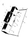
- FIG. 2 is an exploded, perspective view of the modular kitchen system of FIG. 1 but without the modular appliance units.
- FIG. 3 is a sectional view taken along lines 3-3 of FIG. 2.
- FIG. 4 is a sectional view of an alternate embodiment of the mounting rail.
- FIG. 5 is a perspective view of one of the modular units and associated mounting brackets.
- FIG. 6 is a perspective view of the modular kitchen system of the present invention with surrounding kitchen cabinetry.
-
- With reference to FIG. 1, an overall modular kitchen system constructed in accordance with the present invention is generally indicated at 10. As shown, the kitchen system includes a wall assembly which includes a plurality of modules such as a
sink unit 12, arefrigeration unit 14, and ancooking unit 16 which extend from akitchen wall surface 20. Therefrigeration unit 14 andcooking unit 16, may be each referred to as appliance units. Appliance units may also refer to a dishwasher type unit or even an automatic washer type unit. While these units or modules are shown, it can be readily understood that other modules may be incorporated into this modular kitchen system including storage units. All of these units or modules are constructed and assembled together in accordance with the present invention as described more fully below. - The different units or
modules wall 20 through use of amounting rail 30, as shown in FIG. 2. Themounting rail 30 is a multi-functional member which serves to provide: structural support to theappliance units appliance units hood member 24; support to a movable orslidable water tap 26; and finally, a rear portion of the work surface formed by the appliance modules. Themounting rail 30 is securely mounted to thewall 20 through the use of know fastening techniques. - The
mounting rail 30 is an elongated member having anupper portion 32 and alower portion 34. Theupper portion 32 includes atop surface 36 which forms part of the work surface of thekitchen assembly 10 and also provides a support for theslidable water tap 26. A vertically extendingback splash portion 37 may extend from thetop surface 36 upwardly along thewall 20. The back splash may be integrally part of the mounting rail or a separate member. Theslidable water tap 26 is located in a guide orslot 38 and is connected to aflexible hose 40 such that thetap 26 may be allowed to move longitudinally along thekitchen system 10. In this way thetap 26 may be located above thesink unit 12 or above thecooking unit 16 for filling a cooking vessel with water or along any other section of thekitchen system 10. - The
lower portion 34 of therail 30, best shown in FIG. 3, may house a plurality of utility conduits - such as awater inlet 42 and a power orelectricity inlet 44. Further, adrain outlet conduit 46 may be provided. At predetermined locations,inlet pipes utility conduits sink units drain tube 47 may also be teed off from thedrain outlet conduit 46. In this way,appliance units rail 30 and also readily connected to the necessary utilities. Therail 30, when mounted to thewall 20, is connected to external utilities at one location and then distributes these utilities along the lower portion. The utility conduits may also be housed in theupper portion 32. - The
mounting rail 30 may be a unitary structure or may be constructed from a plurality of separate parts. FIG. 4 illustrates an alternative embodiment of the mounting rail 30' where the rail is separated into two elements. In this embodiment, the rail 30' includes a first upper member 32' and a lower member 34'. The upper member 32' supports amovable water tap 26 and houses a plurality of utility inlet pipes 43', 45' that extend from theutility conduits - One of the functions of the mounting
rail 30 is to support themodular units rail 30 includes aguide channel 50, as shown in FIG. 3. Theguide channel 50 extends along the length of the mountingrail 30 and provides an engagement location for a plurality of mountingbrackets 52 which are slidably received onto the mountingrail 30 in a manner wherein anengagement portion 54 is received into the guide channel 50 (see FIG. 3). The mountingbrackets 52 may be preferably formed from metallic material such as stainless steel or aluminum. The mounting brackets include a collar-likemain body 56 that is positioned between the contiguous ends of adjacentmodular units main body 56 receives theend 58 of a unit. Theunit end 58 may be formed with a recessedportion 58a to nest or fit within the collar-likemain body 56. Additionally, the collar-likemain body 58 may be provided with a mechanism (not shown) for tightening themain body 56 about theend 58 of the unit. - FIG. 4 illustrates an alternate embodiment of the mounting
brackets 52. In this embodiment, mountingbrackets 70 are formed as reverse C shaped members. A collar-like main body 72 includes two engagement ends 74 and 76. These engagement ends are received into a pair ofguide channels support leg 77 may extend downwardly from one or more of the mountingbrackets 70 to provide further support for the modular units. - Located at either end of the
modular kitchen system 10 is afinal mounting bracket 52 and anend panel end mount bracket 52 and provide a finished visual appearance. - Looking again at FIGS. 1 and 2, it can be seen that mounting
rail 30 further supports alighting hood member 24. Thehood member 24 includes a pair of upwardly extendingframe elements hood cover 90. Thehood cover 90 may support alight element 92. The power supply to thelight element 92 is provided through one of the frame elements. Acontrol switch 94 may be provided along thetop surface 36 of the mountingrail 30. - As discussed above, the modular kitchen system may include a
sink unit 12, arefrigeration unit 14, and acooking unit 16. The individual units includeend portions 58 that may be received into themain body 56 of the mountingbrackets 52. Moreover, eachend 58 of theunits individual units length mounting rails 30, it is also possible to utilize different numbers of units. - In FIG. 1 it is shown that the
refrigeration unit 14 may comprise adrawer element 98 which includes two cavities 100 and 102 that may be varied in size by movement of amiddle divider element 104. The two cavities 100 and 102 are a fresh food cavity and freezing cavity respectively. By adjusting the location of themiddle divider 104, the size of the cavities can be varied. Moreover, thetop surface 106 of therefrigeration unit 14 may be a transparent material such that it is possible to view the contents of therefrigeration unit 14 without opening thedrawer element 98. - The
cooking unit 16 may be provided with acooktop surface 108 which includes a plurality of heating element (not shown). Below thecooktop surface 108, there is an oven cavity which can be either a conventional oven cavity or a microwave. As previously discussed, it is possible to move thewater tap 26 to directly fill cooking vessels located on the cooktop surface. - It can be seen that the top surface of the
modular kitchen system 10 is formed from a combination of themodular appliance units top surface 36 of the mountingbracket 30. Together, these elements form the top work surface of themodular kitchen system 10 such that no additional counter top material or structure is required. - Turning now to FIG. 6, the
modular kitchen system 10 of the present invention is shown incorporated into a kitchen environment with additional storage units and work surface areas. In this way, the space around and below themodular kitchen system 10 may be beneficially used. - As is apparent from the foregoing specification, the invention is susceptible of being embodied with various alterations and modifications which may differ particularly from those that have been described in the preceding specification and description. It should be understood that we wish to embody within the scope of the patent warranted hereon all such modifications as reasonably and properly come within the scope of our contribution to the art.
Claims (11)
- A modular kitchen system having a plurality of modular kitchen units (12, 14, 16) assembled together and mounted to a kitchen wall, characterized in thatthe plurality of modular units (12, 14, 16) include at least a sink unit (12) and an appliance unit (14, 16),a mounting rail (30) is mounted to the kitchen wall, the mounting rail (30) being an elongated element having an upper portion (32) and a lower portion (34),a movable water tap (26) slidingly supported along the upper portion (32) of the mounting rail,a plurality of mounting brackets (52) slidably connect to the mounting rail (30) and include collar-like main bodies (56) for supporting the plurality of modular units (12, 14, 16) wherein the plurality of units include contiguous ends that substantially match each other and may be received into one of the collar-like main bodies of the mounting brackets for support along the mounting rail.
- The modular kitchen assembly as claimed in claim 1, characterized in that the plurality of modular units (12, 14, 16) include at least a sink unit (12), a refrigeration unit (14) and a cooking unit (16).
- The modular kitchen assembly as claimed in claim 1, characterized in that the mounting rail (30) houses a plurality of utility conduits (42, 44) for supplying power and water to the modular units (12, 14, 16).
- The modular kitchen assembly as claimed in claim 1, characterized in that the mounting rail (30') is formed from an upper member (32') and a separate lower member (34').
- The modular kitchen assembly as claimed in claim 4, characterized in that the upper member (32') houses a plurality of utility conduits (42, 44) for supplying power and water to the modular units (12, 14, 16).
- The modular kitchen assembly as claimed in claim 1, characterized in that a hood member 24 extends from the upper portion (32) of the mounting rail (30).
- The modular kitchen assembly as claimed in claim 6, characterized in the hood member (24) is formed by a pair of frame elements extending upwardly from the mounting rail (30) for supporting a hood cover (90).
- The modular kitchen assembly as claimed in claim 7, characterized in that the electrical power is supplied to a light element (92) mounted within the hood cover (90) through one of the pairs of frame elements and a switch (94) is provided on the mounting rail (30) for controlling energization of the light element.
- The modular kitchen assembly as claimed in claim 1, characterized in that the modular kitchen system includes a top work surface formed by a combination of the modular units and the upper portion of the mounting rail.
- The modular kitchen assembly as claimed in claim 9, characterized in that the plurality of modular units (12, 14, 16) include at least a sink unit (12) and a refrigeration unit (14) and wherein the refrigeration unit includes a drawer (98) and a transparent top surface (106).
- The modular kitchen assembly as claimed in claim 10, characterized in that the plurality of modular units (12, 14, 16) also include a cooking unit (16) upon which cooking vessels may be placed and the movable water tap (26) may be slidingly positioned adjacent the cooking unit for supplying water to such cooking vessels.
Priority Applications (4)
| Application Number | Priority Date | Filing Date | Title |
|---|---|---|---|
| EP04004963A EP1570765B1 (en) | 2004-03-03 | 2004-03-03 | Modular kitchen system |
| PL04004963T PL1570765T3 (en) | 2004-03-03 | 2004-03-03 | Modular kitchen system |
| DE602004013715T DE602004013715D1 (en) | 2004-03-03 | 2004-03-03 | Modular kitchen system |
| ES04004963T ES2305595T3 (en) | 2004-03-03 | 2004-03-03 | MODULAR KITCHEN SYSTEM. |
Applications Claiming Priority (1)
| Application Number | Priority Date | Filing Date | Title |
|---|---|---|---|
| EP04004963A EP1570765B1 (en) | 2004-03-03 | 2004-03-03 | Modular kitchen system |
Publications (2)
| Publication Number | Publication Date |
|---|---|
| EP1570765A1 true EP1570765A1 (en) | 2005-09-07 |
| EP1570765B1 EP1570765B1 (en) | 2008-05-14 |
Family
ID=34745992
Family Applications (1)
| Application Number | Title | Priority Date | Filing Date |
|---|---|---|---|
| EP04004963A Expired - Lifetime EP1570765B1 (en) | 2004-03-03 | 2004-03-03 | Modular kitchen system |
Country Status (4)
| Country | Link |
|---|---|
| EP (1) | EP1570765B1 (en) |
| DE (1) | DE602004013715D1 (en) |
| ES (1) | ES2305595T3 (en) |
| PL (1) | PL1570765T3 (en) |
Cited By (4)
| Publication number | Priority date | Publication date | Assignee | Title |
|---|---|---|---|---|
| CN103284489A (en) * | 2012-03-05 | 2013-09-11 | 松下电器产业株式会社 | Kitchen device |
| WO2018031868A1 (en) * | 2016-08-12 | 2018-02-15 | Capital Timber Frames Llc | Blade based cabinet system |
| US10473336B2 (en) | 2006-04-18 | 2019-11-12 | Oy Halton Group Ltd. | Recirculating exhaust system |
| CN113068951A (en) * | 2020-11-11 | 2021-07-06 | 深圳市商厨科技有限公司 | Splicing modular movable kitchen |
Families Citing this family (1)
| Publication number | Priority date | Publication date | Assignee | Title |
|---|---|---|---|---|
| USD914418S1 (en) | 2019-02-15 | 2021-03-30 | Switch Blade Design Llc | Cabinet frame system |
Citations (8)
| Publication number | Priority date | Publication date | Assignee | Title |
|---|---|---|---|---|
| US3101486A (en) * | 1962-03-23 | 1963-08-27 | American Radiator & Standard | Lavatory fixture |
| US3899228A (en) * | 1972-09-23 | 1975-08-12 | Victor M Schreiber | Storage units |
| EP0363868A1 (en) * | 1988-10-14 | 1990-04-18 | Bonnet S.A. | Kitchen furniture |
| USD313727S (en) | 1987-11-30 | 1991-01-15 | Oscar Gamez | Combined pot and removable handle cover unit |
| US5392934A (en) * | 1993-05-14 | 1995-02-28 | Fox; Larry G. | Apparatus and method for adjustably supporting furnishings on a wall surface |
| US5513908A (en) | 1994-06-02 | 1996-05-07 | Kloppenberg & Company | Modular system for assembling food service fixtures |
| US20030227240A1 (en) | 2002-06-07 | 2003-12-11 | Maytag Corporation | Modular kitchen system |
| DE10235776A1 (en) * | 2002-08-05 | 2004-02-26 | BSH Bosch und Siemens Hausgeräte GmbH | Kitchen module system for incorporating several single functional modules includes single attachable modules each with a functional unit in a casing locked on all sides |
-
2004
- 2004-03-03 EP EP04004963A patent/EP1570765B1/en not_active Expired - Lifetime
- 2004-03-03 PL PL04004963T patent/PL1570765T3/en unknown
- 2004-03-03 ES ES04004963T patent/ES2305595T3/en not_active Expired - Lifetime
- 2004-03-03 DE DE602004013715T patent/DE602004013715D1/en not_active Expired - Lifetime
Patent Citations (8)
| Publication number | Priority date | Publication date | Assignee | Title |
|---|---|---|---|---|
| US3101486A (en) * | 1962-03-23 | 1963-08-27 | American Radiator & Standard | Lavatory fixture |
| US3899228A (en) * | 1972-09-23 | 1975-08-12 | Victor M Schreiber | Storage units |
| USD313727S (en) | 1987-11-30 | 1991-01-15 | Oscar Gamez | Combined pot and removable handle cover unit |
| EP0363868A1 (en) * | 1988-10-14 | 1990-04-18 | Bonnet S.A. | Kitchen furniture |
| US5392934A (en) * | 1993-05-14 | 1995-02-28 | Fox; Larry G. | Apparatus and method for adjustably supporting furnishings on a wall surface |
| US5513908A (en) | 1994-06-02 | 1996-05-07 | Kloppenberg & Company | Modular system for assembling food service fixtures |
| US20030227240A1 (en) | 2002-06-07 | 2003-12-11 | Maytag Corporation | Modular kitchen system |
| DE10235776A1 (en) * | 2002-08-05 | 2004-02-26 | BSH Bosch und Siemens Hausgeräte GmbH | Kitchen module system for incorporating several single functional modules includes single attachable modules each with a functional unit in a casing locked on all sides |
Cited By (8)
| Publication number | Priority date | Publication date | Assignee | Title |
|---|---|---|---|---|
| US10473336B2 (en) | 2006-04-18 | 2019-11-12 | Oy Halton Group Ltd. | Recirculating exhaust system |
| US10634365B2 (en) | 2006-04-18 | 2020-04-28 | Oy Halton Group Ltd. | Modular services supply arrangement |
| US11384941B2 (en) | 2006-04-18 | 2022-07-12 | Oy Halton Group Ltd. | Exhaust hood |
| CN103284489A (en) * | 2012-03-05 | 2013-09-11 | 松下电器产业株式会社 | Kitchen device |
| CN103284489B (en) * | 2012-03-05 | 2015-12-16 | 松下电器产业株式会社 | Kitchen apparatus |
| WO2018031868A1 (en) * | 2016-08-12 | 2018-02-15 | Capital Timber Frames Llc | Blade based cabinet system |
| CN113068951A (en) * | 2020-11-11 | 2021-07-06 | 深圳市商厨科技有限公司 | Splicing modular movable kitchen |
| CN113068951B (en) * | 2020-11-11 | 2023-09-26 | 深圳市商厨科技有限公司 | Spliced modularized movable kitchen |
Also Published As
| Publication number | Publication date |
|---|---|
| DE602004013715D1 (en) | 2008-06-26 |
| ES2305595T3 (en) | 2008-11-01 |
| EP1570765B1 (en) | 2008-05-14 |
| PL1570765T3 (en) | 2008-10-31 |
Similar Documents
| Publication | Publication Date | Title |
|---|---|---|
| US6182305B1 (en) | Cooking sink with cutting board | |
| US6877825B2 (en) | Modular kitchen system | |
| KR100245132B1 (en) | System consisting of kitchen appliance housing units and/or kitchen units | |
| AU2009286975B2 (en) | Camper-van kitchen block | |
| KR102196367B1 (en) | Water server unit | |
| ITPR20130094A1 (en) | FREE INSTALLATION KITCHEN. | |
| EP1570765B1 (en) | Modular kitchen system | |
| ITTV20030110A1 (en) | KITCHEN FURNISHING COMPLEMENT, OF THE OUTDOOR / INTERNAL TYPE, EQUIPPED FOR COOKING FOOD AND WITH A MODULAR STRUCTURE FOR SUPPORTING THE INTERCHANGEABLE FIRE TOP. | |
| JP2026063493A (en) | Kitchen Unit | |
| EP1972873A1 (en) | An appliance and a method for a built-in arrangement in a kitchen interior | |
| CN209950722U (en) | Integrated water tank with induction cooker and multifunctional integrated cabinet thereof | |
| US11185212B2 (en) | Status indicator and lighting assembly for an appliance door | |
| EP0505806B1 (en) | Cooking hob | |
| JP4939992B2 (en) | Kitchen unit | |
| EP1776898A2 (en) | Cooking sink | |
| JPH09238762A (en) | Central control system for system kitchen | |
| CN218295835U (en) | A supplementary mounting structure and integrated kitchen for cooking utensils | |
| US20030177573A1 (en) | Faucet stand | |
| JP2005000190A (en) | Spacer unit | |
| US11134826B2 (en) | Status indicator and lighting assembly for an appliance door | |
| KR102205881B1 (en) | Purifier having Separated Water Discharging Unit | |
| JP2000184921A (en) | Kitchen equipment | |
| JP4098609B2 (en) | Piping cover mounting structure | |
| JPH08117040A (en) | Sink device for kitchen | |
| JPH11137349A5 (en) |
Legal Events
| Date | Code | Title | Description |
|---|---|---|---|
| PUAI | Public reference made under article 153(3) epc to a published international application that has entered the european phase |
Free format text: ORIGINAL CODE: 0009012 |
|
| AK | Designated contracting states |
Kind code of ref document: A1 Designated state(s): AT BE BG CH CY CZ DE DK EE ES FI FR GB GR HU IE IT LI LU MC NL PL PT RO SE SI SK TR |
|
| AX | Request for extension of the european patent |
Extension state: AL LT LV MK |
|
| 17P | Request for examination filed |
Effective date: 20060306 |
|
| AKX | Designation fees paid |
Designated state(s): DE ES FR GB IT PL |
|
| GRAP | Despatch of communication of intention to grant a patent |
Free format text: ORIGINAL CODE: EPIDOSNIGR1 |
|
| GRAS | Grant fee paid |
Free format text: ORIGINAL CODE: EPIDOSNIGR3 |
|
| GRAA | (expected) grant |
Free format text: ORIGINAL CODE: 0009210 |
|
| AK | Designated contracting states |
Kind code of ref document: B1 Designated state(s): DE ES FR GB IT PL |
|
| REG | Reference to a national code |
Ref country code: GB Ref legal event code: FG4D |
|
| REF | Corresponds to: |
Ref document number: 602004013715 Country of ref document: DE Date of ref document: 20080626 Kind code of ref document: P |
|
| REG | Reference to a national code |
Ref country code: PL Ref legal event code: T3 |
|
| REG | Reference to a national code |
Ref country code: ES Ref legal event code: FG2A Ref document number: 2305595 Country of ref document: ES Kind code of ref document: T3 |
|
| PLBE | No opposition filed within time limit |
Free format text: ORIGINAL CODE: 0009261 |
|
| STAA | Information on the status of an ep patent application or granted ep patent |
Free format text: STATUS: NO OPPOSITION FILED WITHIN TIME LIMIT |
|
| 26N | No opposition filed |
Effective date: 20090217 |
|
| REG | Reference to a national code |
Ref country code: FR Ref legal event code: PLFP Year of fee payment: 13 |
|
| PGFP | Annual fee paid to national office [announced via postgrant information from national office to epo] |
Ref country code: DE Payment date: 20160223 Year of fee payment: 13 Ref country code: ES Payment date: 20160211 Year of fee payment: 13 |
|
| PGFP | Annual fee paid to national office [announced via postgrant information from national office to epo] |
Ref country code: FR Payment date: 20160208 Year of fee payment: 13 Ref country code: GB Payment date: 20160302 Year of fee payment: 13 |
|
| PGFP | Annual fee paid to national office [announced via postgrant information from national office to epo] |
Ref country code: IT Payment date: 20160324 Year of fee payment: 13 |
|
| PGFP | Annual fee paid to national office [announced via postgrant information from national office to epo] |
Ref country code: PL Payment date: 20170112 Year of fee payment: 14 |
|
| REG | Reference to a national code |
Ref country code: DE Ref legal event code: R119 Ref document number: 602004013715 Country of ref document: DE |
|
| GBPC | Gb: european patent ceased through non-payment of renewal fee |
Effective date: 20170303 |
|
| REG | Reference to a national code |
Ref country code: FR Ref legal event code: ST Effective date: 20171130 |
|
| PG25 | Lapsed in a contracting state [announced via postgrant information from national office to epo] |
Ref country code: DE Free format text: LAPSE BECAUSE OF NON-PAYMENT OF DUE FEES Effective date: 20171003 Ref country code: FR Free format text: LAPSE BECAUSE OF NON-PAYMENT OF DUE FEES Effective date: 20170331 |
|
| PG25 | Lapsed in a contracting state [announced via postgrant information from national office to epo] |
Ref country code: GB Free format text: LAPSE BECAUSE OF NON-PAYMENT OF DUE FEES Effective date: 20170303 Ref country code: IT Free format text: LAPSE BECAUSE OF NON-PAYMENT OF DUE FEES Effective date: 20170303 |
|
| REG | Reference to a national code |
Ref country code: ES Ref legal event code: FD2A Effective date: 20180705 |
|
| PG25 | Lapsed in a contracting state [announced via postgrant information from national office to epo] |
Ref country code: ES Free format text: LAPSE BECAUSE OF NON-PAYMENT OF DUE FEES Effective date: 20170304 |
|
| PG25 | Lapsed in a contracting state [announced via postgrant information from national office to epo] |
Ref country code: PL Free format text: LAPSE BECAUSE OF NON-PAYMENT OF DUE FEES Effective date: 20180303 |