EP1569216A1 - Magneto-optical storage medium reproduction method and magneto-optical storage apparatus using the method - Google Patents
Magneto-optical storage medium reproduction method and magneto-optical storage apparatus using the method Download PDFInfo
- Publication number
- EP1569216A1 EP1569216A1 EP02783687A EP02783687A EP1569216A1 EP 1569216 A1 EP1569216 A1 EP 1569216A1 EP 02783687 A EP02783687 A EP 02783687A EP 02783687 A EP02783687 A EP 02783687A EP 1569216 A1 EP1569216 A1 EP 1569216A1
- Authority
- EP
- European Patent Office
- Prior art keywords
- magnetic field
- reproductive
- magneto
- permanent magnet
- strength
- Prior art date
- Legal status (The legal status is an assumption and is not a legal conclusion. Google has not performed a legal analysis and makes no representation as to the accuracy of the status listed.)
- Withdrawn
Links
Images



Classifications
-
- G—PHYSICS
- G11—INFORMATION STORAGE
- G11B—INFORMATION STORAGE BASED ON RELATIVE MOVEMENT BETWEEN RECORD CARRIER AND TRANSDUCER
- G11B11/00—Recording on or reproducing from the same record carrier wherein for these two operations the methods are covered by different main groups of groups G11B3/00 - G11B7/00 or by different subgroups of group G11B9/00; Record carriers therefor
- G11B11/10—Recording on or reproducing from the same record carrier wherein for these two operations the methods are covered by different main groups of groups G11B3/00 - G11B7/00 or by different subgroups of group G11B9/00; Record carriers therefor using recording by magnetic means or other means for magnetisation or demagnetisation of a record carrier, e.g. light induced spin magnetisation; Demagnetisation by thermal or stress means in the presence or not of an orienting magnetic field
- G11B11/105—Recording on or reproducing from the same record carrier wherein for these two operations the methods are covered by different main groups of groups G11B3/00 - G11B7/00 or by different subgroups of group G11B9/00; Record carriers therefor using recording by magnetic means or other means for magnetisation or demagnetisation of a record carrier, e.g. light induced spin magnetisation; Demagnetisation by thermal or stress means in the presence or not of an orienting magnetic field using a beam of light or a magnetic field for recording by change of magnetisation and a beam of light for reproducing, i.e. magneto-optical, e.g. light-induced thermomagnetic recording, spin magnetisation recording, Kerr or Faraday effect reproducing
- G11B11/10595—Control of operating function
-
- G—PHYSICS
- G11—INFORMATION STORAGE
- G11B—INFORMATION STORAGE BASED ON RELATIVE MOVEMENT BETWEEN RECORD CARRIER AND TRANSDUCER
- G11B11/00—Recording on or reproducing from the same record carrier wherein for these two operations the methods are covered by different main groups of groups G11B3/00 - G11B7/00 or by different subgroups of group G11B9/00; Record carriers therefor
- G11B11/10—Recording on or reproducing from the same record carrier wherein for these two operations the methods are covered by different main groups of groups G11B3/00 - G11B7/00 or by different subgroups of group G11B9/00; Record carriers therefor using recording by magnetic means or other means for magnetisation or demagnetisation of a record carrier, e.g. light induced spin magnetisation; Demagnetisation by thermal or stress means in the presence or not of an orienting magnetic field
- G11B11/105—Recording on or reproducing from the same record carrier wherein for these two operations the methods are covered by different main groups of groups G11B3/00 - G11B7/00 or by different subgroups of group G11B9/00; Record carriers therefor using recording by magnetic means or other means for magnetisation or demagnetisation of a record carrier, e.g. light induced spin magnetisation; Demagnetisation by thermal or stress means in the presence or not of an orienting magnetic field using a beam of light or a magnetic field for recording by change of magnetisation and a beam of light for reproducing, i.e. magneto-optical, e.g. light-induced thermomagnetic recording, spin magnetisation recording, Kerr or Faraday effect reproducing
- G11B11/10502—Recording on or reproducing from the same record carrier wherein for these two operations the methods are covered by different main groups of groups G11B3/00 - G11B7/00 or by different subgroups of group G11B9/00; Record carriers therefor using recording by magnetic means or other means for magnetisation or demagnetisation of a record carrier, e.g. light induced spin magnetisation; Demagnetisation by thermal or stress means in the presence or not of an orienting magnetic field using a beam of light or a magnetic field for recording by change of magnetisation and a beam of light for reproducing, i.e. magneto-optical, e.g. light-induced thermomagnetic recording, spin magnetisation recording, Kerr or Faraday effect reproducing characterised by the transducing operation to be executed
- G11B11/10515—Reproducing
-
- G—PHYSICS
- G11—INFORMATION STORAGE
- G11B—INFORMATION STORAGE BASED ON RELATIVE MOVEMENT BETWEEN RECORD CARRIER AND TRANSDUCER
- G11B11/00—Recording on or reproducing from the same record carrier wherein for these two operations the methods are covered by different main groups of groups G11B3/00 - G11B7/00 or by different subgroups of group G11B9/00; Record carriers therefor
- G11B11/10—Recording on or reproducing from the same record carrier wherein for these two operations the methods are covered by different main groups of groups G11B3/00 - G11B7/00 or by different subgroups of group G11B9/00; Record carriers therefor using recording by magnetic means or other means for magnetisation or demagnetisation of a record carrier, e.g. light induced spin magnetisation; Demagnetisation by thermal or stress means in the presence or not of an orienting magnetic field
- G11B11/105—Recording on or reproducing from the same record carrier wherein for these two operations the methods are covered by different main groups of groups G11B3/00 - G11B7/00 or by different subgroups of group G11B9/00; Record carriers therefor using recording by magnetic means or other means for magnetisation or demagnetisation of a record carrier, e.g. light induced spin magnetisation; Demagnetisation by thermal or stress means in the presence or not of an orienting magnetic field using a beam of light or a magnetic field for recording by change of magnetisation and a beam of light for reproducing, i.e. magneto-optical, e.g. light-induced thermomagnetic recording, spin magnetisation recording, Kerr or Faraday effect reproducing
- G11B11/10532—Heads
- G11B11/10541—Heads for reproducing
-
- G—PHYSICS
- G11—INFORMATION STORAGE
- G11B—INFORMATION STORAGE BASED ON RELATIVE MOVEMENT BETWEEN RECORD CARRIER AND TRANSDUCER
- G11B11/00—Recording on or reproducing from the same record carrier wherein for these two operations the methods are covered by different main groups of groups G11B3/00 - G11B7/00 or by different subgroups of group G11B9/00; Record carriers therefor
- G11B11/10—Recording on or reproducing from the same record carrier wherein for these two operations the methods are covered by different main groups of groups G11B3/00 - G11B7/00 or by different subgroups of group G11B9/00; Record carriers therefor using recording by magnetic means or other means for magnetisation or demagnetisation of a record carrier, e.g. light induced spin magnetisation; Demagnetisation by thermal or stress means in the presence or not of an orienting magnetic field
- G11B11/105—Recording on or reproducing from the same record carrier wherein for these two operations the methods are covered by different main groups of groups G11B3/00 - G11B7/00 or by different subgroups of group G11B9/00; Record carriers therefor using recording by magnetic means or other means for magnetisation or demagnetisation of a record carrier, e.g. light induced spin magnetisation; Demagnetisation by thermal or stress means in the presence or not of an orienting magnetic field using a beam of light or a magnetic field for recording by change of magnetisation and a beam of light for reproducing, i.e. magneto-optical, e.g. light-induced thermomagnetic recording, spin magnetisation recording, Kerr or Faraday effect reproducing
- G11B11/1055—Disposition or mounting of transducers relative to record carriers
- G11B11/10556—Disposition or mounting of transducers relative to record carriers with provision for moving or switching or masking the transducers in or out of their operative position
- G11B11/1056—Switching or mechanically reversing the magnetic field generator
Definitions
- the present invention relates to a reproducing method of a magneto-optical storage medium that performs recording and reproducing of information using light and a magnetic field, and a to magneto-optical storage apparatus using the reproducing method.
- a representative example of the external storage device is a 3.5-inch magneto-optical disc.
- MB Megabytes
- GB gigabytes
- MSR Magnetically induced Super Resolution
- MSR technology using the MSR medium have been adopted from the 1.3GB products on.
- the MSR medium for example, has three layers: a reproducing layer, a middle layer and a recording layer, and binary data is recorded in the recording layer as a recorded mark which is smaller than a beam spot generated by a laser beam applied to the medium.
- a reproducing layer When the laser beam is applied to a rotating magneto-optical disc, areas of different temperatures are generated within the beam spot, and when a reproductive magnetic field is applied there, an area (mask) of the reproducing layer with one magnetization direction is formed within the beam spot due to the properties of the MSR medium.
- the MSR technology includes a reproducing method that masks a given area within a beam spot and enables the reading of a recorded mark located in an aperture that is not masked by controlling a laser beam and a reproductive magnetic field at reproducing.
- a reproducing method that masks a given area within a beam spot and enables the reading of a recorded mark located in an aperture that is not masked by controlling a laser beam and a reproductive magnetic field at reproducing.
- a greater intensity of a reproductive magnetic field is sometimes required to reproduce the MSR medium than to record (to erase) data.
- multiple masks are sometimes formed at reproducing in the MSR technology.
- the temperature in an area of the front mask side is lower than that in an area of the rear mask side and the front mask has a given level of coercive force.
- the reproductive magnetic field must be greater than the given coercive force and the front mask must be applied with the greater magnetic field than the rear mask. Therefore, coupled with the optimization described earlier, the balance of the reproductive magnetic field has to be well controlled.
- Japanese Patent Application Laid-Open Publication No. 2001-176141 discloses a method to set up an optimum reproductive laser power (irradiated light intensity), however the document does not refer to the optimization of the reproductive magnetic field strength.
- Japanese Patent Application Laid-Open Publication No. 1999-259925 discloses a method to set the intensities of the reproductive magnetic field and of the reproductive laser power (irradiated light intensity) optimally using a super-resolution technology, however the method is limited to only when a mask is formed on the front or rear side and thus the document does not refer to the balance of the reproductive magnetic field intensities when masks are formed on both front and rear sides.
- Japanese Patent Application Laid-Open Publication No. 1997-204706 discloses a magneto-optical recording and reproducing apparatus that controls the magnetic field strength to an optimum value by controlling the position of a permanent magnet, however the document does not refer to a reproductive error rate.
- other related documents such as Japanese Patent Application Laid-Open Publication Nos. 1992-278239, 1993-62276 and 1990-154301 are also available, however none of them are aimed at optimizing the magnetic field strength and the irradiated light intensity.
- the irradiated light intensity and the reproductive magnetic field have to be appropriately selected for optimization in reproducing information using the MSR medium. Also, when the front mask and the rear mask are used to reproduce, it is desirable to control the reproductive magnetic field in such a way that the front mask is applied with a greater reproductive magnetic field strength than that the rear mask. Furthermore, it is also desirable to use the permanent magnet to reduce the power consumption and to be able to control to maintain the optimized reproductive magnetic field strength.
- the object of the present invention is to provide a magneto-optical disc apparatus and a method of reproducing information with the optimized irradiated light intensity and optimized reproductive magnetic field.
- the above object is achieved by the provision of a magneto-optical storage apparatus capable of using a magneto-optical storage medium provided with a recording layer and a reproducing layer.
- information in the recording layer is transferred to the reproducing layer through irradiation of light at a given intensity for reproduction and through application of a reproductive magnetic field.
- the information contained in a given area thereof is enabled to be reproduced.
- the apparatus includes: an optical head irradiating light to the given area at least at a given intensity for reproduction; a permanent magnet applying at least the reproductive magnetic field to the given area; and a control unit controlling the optical head and the permanent magnet to reproduce the information, calculating a reproductive error rate associated with the reproduction and altering the strength of the reproductive magnetic field based on the reproductive error rate.
- the control unit further alters the strength of the reproductive magnetic field to a strength at which a given width for strength changes is secured within a range of a magnetic field strength where the reproductive error rate satisfies a given criteria that enables reproduction.
- the control unit further alters the strength of the reproductive magnetic field to a strength at which the reproductive error rate is minimized within a range of a magnetic field strength where the reproductive error rate satisfies a given criteria that enables reproduction.
- the magneto-optical storage apparatus of the present invention further includes a magnetic sensor measuring the magnetic field strength of the permanent magnet, wherein the control unit further controls the permanent magnet to keep the magnetic field strength measured by the magnetic sensor at the altered reproductive magnetic field strength.
- the magneto-optical storage apparatus of the present invention further includes unit measuring the distance between the optical head and the magneto-optical storage medium, wherein the control unit further controls the permanent magnet to keep the altered reproductive magnetic field strength in response to the measured distance.
- the permanent magnet is rotatable around a rotational axis, and the control unit controls the permanent magnet by altering the angle of the permanent magnet.
- the permanent magnet is displaceable in a horizontal direction parallel to the magneto-optical storage medium, and the control unit controls the permanent magnet by altering the horizontal position of the permanent magnet.
- the above object is achieved by the provision of reproducing method of a magneto-optical storage medium provided with a recording layer and a reproducing layer.
- information in the recording layer is transferred to the reproducing layer through irradiation of light at a given intensity for reproduction and through application of a reproductive magnetic field.
- the information contained in a given area thereof is enabled to be reproduced.
- the method includes the steps of: irradiating light for reproduction to the given area; applying the reproductive magnetic field to the given area by a permanent magnet; reproducing the information by use of the irradiation light and the reproductive magnetic field; calculating a reproductive error rate associated with the reproduction; and altering the strength of the reproductive magnetic field to be applied by the permanent magnet, based on the reproductive error rate.
- the information reproducing method of a magneto-optical storage medium which allows information to be reproduced through applications of the irradiated light intensity and the reproductive magnetic field with a permanent magnet, and the magneto-optical storage apparatus using the reproducing method, information can be reproduced in the optimum reproductive magnetic field while keeping the reproductive error rate below a given order by optimizing the reproductive magnetic field strength with the irradiated light intensity being set higher than a given intensity.
- the calorific value can be reduced with the use of the permanent magnet as compared to an electromagnet, which in turn can suppress an increase in the reproductive magnetic field strength at a high temperature. Also, by displacing the permanent magnet, a portion having the highest magnetic flux density of the permanent magnet can be efficiently applied to an area that needs the magnetic field most when reproducing. For a permanent magnet, the one that controls the magnetic field strength by changing the orientation, the one by changing a horizontal position and so forth can be used.
- signals can be reproduced in a more stabilized manner with a feedback control, which constantly monitors the intensity of the magnetic field and controls to keep the monitoring signals steady, even if the reproductive magnetic field strength fluctuates due to vibrations that the apparatus receives.
- a focus servo control circuit is provided to monitor the distance between the magneto-optical storage medium and an optical head to keep the intensity of the magnetic field that the medium receives constantly stable.
- the reproductive magnetic field can be set to optimum in accordance with the change.
- Fig. 6 describes an existing information reproducing.
- Fig. 6A describes the way of a laser beaming at a magneto-optical disc medium.
- the magneto-optical disc medium 601 rotates in an anticlockwise direction 602.
- a laser beam 604 from an optical head 603 is applied to the magneto-optical disc medium 601 and a beam spot 605 is formed on the medium.
- Fig. 6B is a top view of the magneto-optical disc medium 601 seen from a vertical direction 606 in Fig. 6A against the magneto-optical disc medium. A portion of the magneto-optical disc medium 601 is excerpted. Many tracks 617 exist on the magneto-optical disc medium 601 and information is recorded on the tracks as a recorded mark 615. The recorded mark 615 is in a recording layer 625 to be described and the mark is transferred to a reproducing layer 623 to be also described and reproduced.
- Fig. 6B shows a state of a front mask 611, an aperture 612 and a rear mask 613 being formed within the beam spot 605.
- the recorded mark is included in the beam spot 605.
- the front mask, the rear mask and the aperture will be described later.
- the beam spot 605 appears as if to proceed to a direction 618, which is opposite the rotation direction 602 of the medium.
- a beam's seeming traveling direction side 618 is called front and a side of the medium's rotating direction 602 is called rear.
- the front mask is not shown but is spread across the front, and a recorded mark 614 is located in the front mask 611, a recorded mark 615 in the aperture 612 and a recorded mark 616 in the rear mask 613 in Fig. 6B.
- Fig. 6C is a sectional view of a middle track in Fig. 6 when the magneto-optical disc medium 601 is seen from a lateral direction 607 in Fig. 6A.
- the magneto-optical disc medium 601 using the MSR medium includes of a reproducing layer 623, a middle layer 624 and a recording layer 625.
- the recording layer 625 information is recorded as a recorded mark using magnetization of a recording direction 622 and an erasing direction 621 that face against each other in order to record binary data of 0 and 1.
- an upward arrow is represented by the recording direction 622 and a downward arrow by the erasing direction 621.
- the three layers have the following properties. First, concerning coercive force, the recording layer 625 has higher coercive force than the other two layers at ambient temperature. Next, concerning switched connection force, the switched connection force of the reproducing layer 623 and the middle layer 624 is strong at ambient temperature and magnetization directions of these two layers go against each other. At a given temperature, the switched connection of the recording layer 625, the middle layer 624 and the reproducing layer 623 become stronger. As a result, at the given temperature, information in the recording layer is to be transferred to the reproducing layer. Further, at a temperature higher than the given temperature, the reproducing layer 623 and the middle layer 624 have a property to lose the switched connection between them.
- the middle layer 624 is more susceptible to receiving effects of the reproductive magnetic field than the reproducing layer 623 is at ambient temperature, and the middle layer is magnetized to the same direction as the reproductive magnetic field. Then the reproducing layer is magnetized to the opposite by the switched connection. Also, at a temperature at which the switched connection of the reproducing layer 623 and the middle layer 624 is lost, the reproducing layer is affected by the reproductive magnetic field and becomes magnetized in the same direction as the reproductive magnetic field.
- the temperature that the recording layer is affected by the reproductive magnetic field is higher than the temperature at which the switched connection of the reproducing layer 623 and the middle layer 624 is lost, thus the recording layer is not affected by the reproductive magnetic field at the temperature of which the switched connection of the reproducing layer 623 and the middle layer 624 is lost.
- the time applied with the laser beam is short for the recorded mark 614 in Fig. 6C and thus has the lowest temperature in the beam spot 605.
- a temperature of the recorded mark 615 in the center of the beam spot 605 is higher than that of the recorded mark 614.
- the time applied with the laser beam is longer for the recorded mark 616 than for the other recorded marks in the beam spot 605 and thus its temperature is higher than that of the recorded mark 615.
- the laser beam is controlled so that the recorded mark 614 becomes at ambient temperature, the recorded mark 615 at the given temperature of which the transfer from the recording layer 625 to the reproducing layer 623 takes place, and the recorded mark 616 at the temperature of the switched connection of the reproducing layer 623 and the middle layer 622 becomes lost.
- the reproductive magnetic field 626 that is in the same direction as the recording direction 622 is applied here.
- the middle layer 624 is magnetized into the recording direction 622 at the position of the recorded mark 614, and the reproducing layer 623 becomes magnetized into the erasing direction 621 by the switched connection.
- the reproducing layer 623 is magnetized into the recording direction.
- an area that has the same magnetization direction as the recorded mark 614 is formed at the recorded mark on the front side.
- an area that has the same magnetization direction as the recorded mark 616 is formed at the recorded mark on the rear side. They are the front mask 611 and the rear mask 613 respectively.
- the front mask 611 which is magnetized into the direction opposite from that of the reproductive magnetic field 626 (the erasing direction 621 in Fig. 6C), is formed in the front side of the reproducing layer 623
- the rear mask 613 which is magnetized into the same direction as that of the reproductive magnetic field 626 (the recording direction 622 in Fig. 6C) is formed in the rear side of the reproducing layer 623.
- the oval shaped rear mask 613 is formed on the rear side by the rotation of the magneto-optical disc medium 616 and thermal diffusion
- the crescent-shaped aperture 612 is formed from the beam spot 605, which is not covered by neither the front mask 611 nor the rear mask 613.
- the magnetization direction of the recording layer which has been transferred to the reproducing layer at the position of the recorded mark 615, determines the direction of magnetization included in reflected lights from the beam spot 605. Therefore, by analyzing the reflected lights from the beam spot 605, the recorded mark 615 is accurately reproduced though it is smaller than the beam spot 605.
- the magneto-optical disc apparatus which enables the MSR medium to be reproduced upon optimizing the intensities of the laser beam and of the reproductive magnetic field to be applied, and the reproducing method will be described in a mode for carrying out the present invention. Also, concerning optimization, the magneto-optical disc apparatus with which the magnetic field is set to exert higher intensity on the front mask, which requires the stronger reproductive magnetic field, than on the rear mask will be described along with the reproducing method.
- the permanent magnet is used to lower the power consumption for the overall apparatus.
- Fig. 1 shows a configuration example of an embodiment of the magneto-optical disc apparatus of the present invention.
- the magneto-optical disc apparatus records information onto the magneto-optical disc medium and reproduces the recorded information using light and magnetism.
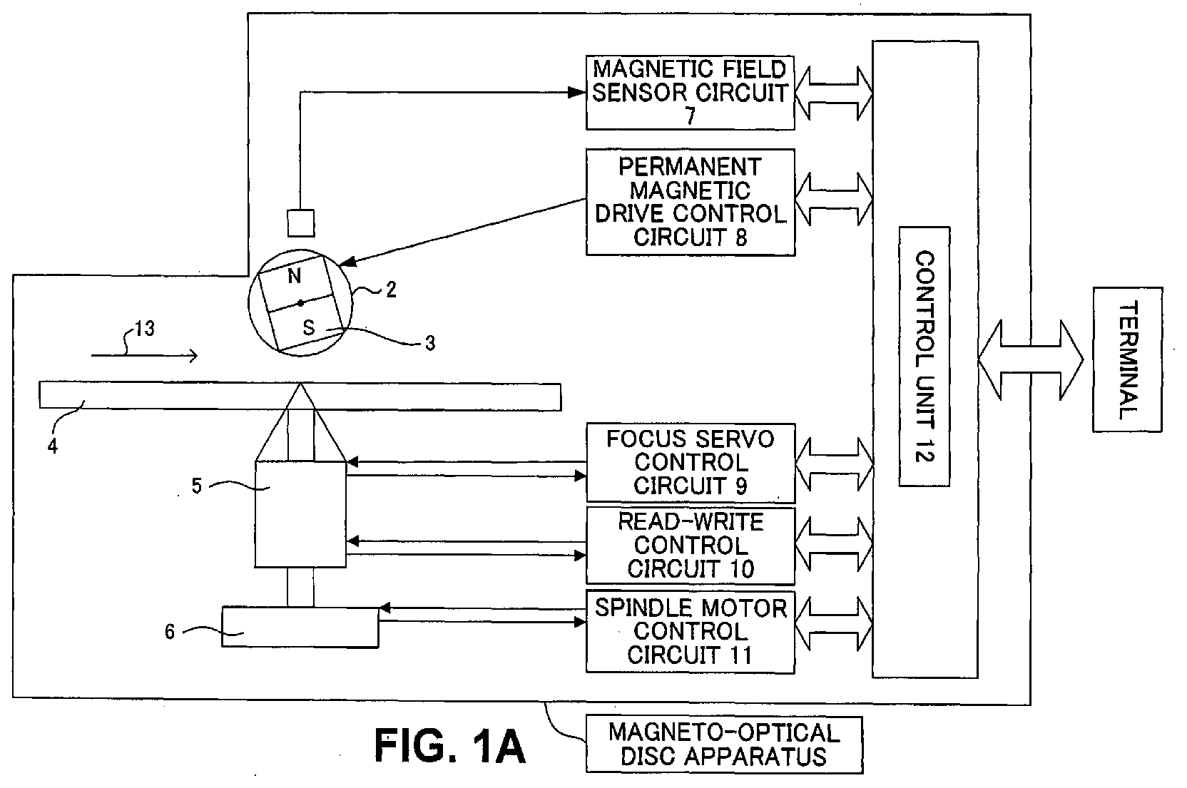
- Fig. 1A especially shows devices and circuits associated mainly with reproducing of the magneto-optical disc medium 4, of the magneto-optical disk apparatus, with the magneto-optical disc medium 4 and an optical head 5 being viewed from a direction 14 in Fig. 1B.
- the magneto-optical disc medium is connected to a terminal such as a computer through an interface not shown in control unit 12, and an instruction to record or reproduce and information from the terminal are transmitted to and from the control unit 12.
- the magneto-optical disc medium 4 is forced to rotate in a rotating direction 13 by a spindle motor 6.
- the rotating magneto-optical disc medium is applied with the laser beam from the optical head 5 and then is applied with the magnetic field by the permanent magnet 3 to carry out recording and reproducing of information.
- An MSR medium is used as the magneto-optical disc medium 4.
- the permanent magnet 3 is supported by a support unit 2 and is displaced by a permanent magnet drive control circuit 8.
- a permanent magnet drive control circuit 8 By displacing the permanent magnet 3, the magnetic field strength to apply the magneto-optical disc medium 4 can be appropriately modified.
- a bar-shaped permanent magnet that revolves around an axis is drawn in Fig. 1A and the position and the magnetic field strength is modified through controlling the rotation of the axis.
- a magnetic sensor 1 detects the magnetic field strength of the permanent magnet 3. The sensor is used to monitor the magnetic field strength to be applied with and any fluctuations in the magnetic field strength due to vibrations of the apparatus.
- a focus servo control circuit 9 controls the intensity of the laser beam to be applied with and monitors the distance between the magneto-optical disc medium 4 and the optical head 5. If the distance between the optical head 5 and the magneto-optical disc medium 4 fluctuates due to vibrations of the magneto-optical disc apparatus or of the magneto-optical disc medium surface, the distance between the permanent magnet 3 and the magneto-optical disc medium 4 is also modified and the feedback control is carried out to maintain the reproductive magnetic field strength properly in conjunction with the control unit 12 to be described later.
- a read-write control circuit 10 moves the optical head 5 to a given address on the magneto-optical disc medium 4 to be recorded or reproduced and controls sending and receiving of information to be recorded or reproduced.
- a spindle motor control circuit 11 controls the rotation of the spindle motor 6.
- the control unit 12 stores a CPU that carries out overall control over the magneto-optical disc apparatus not shown along with computed results and setups done in the CPU, and the unit also has a memory not shown that stores programs to control the CPU.
- the control unit 12 issues control instructions to a magnetic field sensor circuit 7, the permanent magnet drive control circuit 8, the focus servo control circuit 9, the read-write control circuit 10, and the spindle motor control circuit 11. For example, if the magnetic field sensor circuit 7 has detected that the magnetic field strength has fluctuated from the optimum one, the control unit 12 will instruct the permanent magnet drive control circuit 8 to move the permanent magnet 3 to a position where the optimum magnetic field strength can be maintained.
- the control unit will instruct the permanent magnet drive control circuit 8 to move the permanent magnet 3 to a position where a magnetic field strength necessary for each operation of recording, erasing or reproducing information can be maintained.
- the method of reproducing information in the present invention is to control the reproductive magnetic field and the laser beam a magnetic field strength and a irradiated light intensity decided respectively based on a process to determine the optimum magnetic field strength shown in Fig. 2 to optimize the reproductive magnetic field.
- An example diagram in Fig. 3 shows the distribution of bit error rates (reproductive error rates) in reproducing information according to combinations of the reproductive magnetic field strength and the irradiated light intensity.
- Fig. 2 is a flowchart that explains the process to determine the optimum magnetic field strength.
- the irradiated light intensity is set at an initial value (S21).
- a given value is set as the initial value for the irradiated light intensity.
- the control unit 12 instructs the focus servo control circuit 9 to irradiate the laser beam at the given intensity based on the given value read out of the memory.
- the focus servo control circuit 9 controls the irradiated light intensity of the optical head 5 based on the instruction received from the control unit 12.
- FIG. 3 An example diagram in Fig. 3 shows the distribution of the bit error rates (reproductive error rates) in reproducing information according to combinations of the reproductive magnetic field strength and the irradiated light intensity.
- the vertical axis shows the irradiated light intensity and the horizontal axis the reproductive magnetic field strength, and the reproductive error rate that corresponds to a combination of the two intensities is drawn into the diagram.
- the example shows that reproducing is performed more accurately if the reproductive error rate is lower, and reproducing has to be carried out with the reproductive error rate being in an order of 10 to the -5th power for a reproduction standard of the apparatus here.
- the reproductive error rates are: an order of 10 to the -1st power for an area 31 labeled as -1 to 0,; of 10 to the -2nd power for an area 32 labeled as -2 to -1; of 10 to the -3rd power for an area 33 labeled as -3 to -2; of 10 to the -4th power for an area 34 labeled as -4 to -3; and of 10 to the -5th power for an area 35 labeled as -5 to -4.
- the area 35 is called a reproducible area and it is important to select the irradiated light intensity and the reproductive magnetic field strength in such an order of 10 to the -5th power for the reproductive error rate.
- the lower bound of the irradiated light intensity such as above is called the smallest reproductive power.
- the smallest reproductive power differs depending on materials used for the magneto-optical disc medium, however if materials of the magneto-optical disc medium can be identified, the smallest reproductive power can be also identified.
- the initial value for the irradiated light intensity is set to the smallest reproductive power. Since the smallest reproductive power can be identified if a magneto-optical disc medium is specified, the control unit 12 is to read out the smallest reproductive power of a corresponding magneto-optical disc medium in the memory (not shown) which records the smallest reproductive power for each magneto-optical disc medium in the control unit 12. Another way to determine the initial value of the irradiated light intensity is to use a given value that has been set without specifying a magneto-optical disc medium and then to modify the irradiated light intensity later.
- the reproductive magnetic field is set to an initial value (S22).
- a given value is set as an initial value for the reproductive magnetic field strength.
- the control unit 12 instructs the permanent magnet drive control circuit 8 to displace the position of the permanent magnet 3 to where it can achieve the magnetic field strength based on the given value read out of the memory.
- the permanent magnet drive control circuit 8 drives the permanent magnet 3 based on the instructions received from the control unit 12.
- the control unit 12 instructs the read-write control circuit 10 to execute reproducing of information.
- the read-write control circuit 10 moves the optical head 5 to a position on the magneto-optical disc medium that is recorded with information to be reproduced, reproduces the information and sends the information regarding the occurrence of a reproductive error to the control unit 12. Based on the error information, the control unit can obtain a reproductive error rate.
- control unit 12 first creates a test pattern and then stores it in the memory, which has not been illustrated. Then the unit erases the information on the sector subject to testing on a test track set up in a given area of the storage medium. After the information in the sector subjected to testing is erased, the test pattern stored in the buffer memory is recorded in the sector subjected to testing.
- the control unit 12 After recording the test pattern into the sector subject to testing, the control unit 12 sets the irradiated light intensity for the laser spot and the magnetic field strength to the values obtained at the steps S21 and S22, and reproduces the test pattern from the sector subject to testing. Then the test pattern reproduced is compared to the original one stored in the memory and the bit error rates in reproduction (reproductive error rates) is calculated and stored in the memory in the control unit that is not shown. By repeating this procedure as the magnetic field strength is modified, for example, a magnetic field strength with the lowest reproductive error rate can be obtained.
- the permanent magnet 3 is displaced and information is reproduced with a newly set reproductive magnetic field strength to calculate the reproductive error rate involved in reproduction (S24).
- the displacement of the permanent magnet and calculation of the error rates are the same as the step S22 and S23. How the permanent magnet is displaced differs depending on the magneto-optical disc apparatus and the shape of the permanent magnet provided. Rotating the permanent magnet, changing its horizontal position and such are some of the examples.
- step S24 is repeated until the given conditions are satisfied (S25).
- a given condition is to repeat the step until the calculation of a reproductive error rate for one rotation is complete.
- calculation of a reproductive error rate is repeated until the magnet fully travels its operating range in the horizontal position.
- the calculation can be also repeated till the upper and lower bounds of the reproductive magnetic field strength that satisfy the conditions for the reproducible area are found. Or, having the number of observation points for the reproductive error rates specified, calculation of the reproductive error rates can be repeated until more than the number specified are measured.
- reproduction is carried out with a newly set irradiated light intensity, which has been changed from the smallest reproductive power specified in the step S21, and the reproductive error rates are compared to decide a superior irradiated light intensity of the two for use and then the steps S22 and S23 are to be worked over.
- an optimum value is determined from the range of the magnetic field strength that satisfies the criteria for which the reproductive error rate calculated can be included in the reproducible area (S26).
- the reproductive error rate becomes higher when the front mask and the rear mask are not formed properly.
- the front mask requires a higher reproductive magnetic field strength, thus if the magnetic field applied to the front mask is weak, cross talk will take place and the reproductive error rate rises.
- a reproductive magnetic field with the lowest reproductive error rate is chosen, a condition of having the front mask being applied with a stronger forming magnetic field than the rear mask can be created.
- whether or not the front mask requires a stronger forming magnetic field than the rear mask does is dependent on the materials in the medium coating structure and thus the rear mask may require a stronger forming magnetic field than the front mask does depending on coating structures.
- the control for such a case is the opposite of the one with the front mask needing a stronger forming magnetic field than the rear mask.
- the distribution in Fig. 3 moves toward the right as a whole and the range of the reproductive magnetic field strength required at a given irradiated light intensity shifts further toward the higher end of the magnetic field strength.
- the method to determine the reproductive magnetic field strength with the smallest reproductive error rate above can be applied.
- the distribution in Fig. 3 moves toward the right as a whole and the range of the reproductive magnetic field strength required at a given irradiated light intensity shifts further toward the higher end of the magnetic field strength.
- the method to determine the reproductive magnetic field strength that measures the upper and lower bounds of the reproducible reproductive magnetic field strength can be applied.
- the process to determine the magnetic field strength for example, it can be carried out when the storage medium is inserted, once every specified time, when a recording or reproductive command is issued for the first time after inserting the medium, at retrying after an error, at a temperature change and so forth.
- the information reproducing method is stored as a program in the memory of the control unit 12, it can be executed as a magneto-optical disc apparatus to reproduce the MSR medium with the optimized irradiated light intensity and reproductive magnetic field strength.
- the reproductive magnetic field is modified with the irradiated light intensity being set higher than a given intensity and then the optimum reproductive magnetic field is set based on the reproductive error rates obtained. Also, by choosing a reproductive magnetic field that has the smallest reproductive error rate in the reproducible area, a stronger magnetic field can be applied to the front mask than to the rear mask.
- reproductive magnetic field has fluctuated
- stable reproduction can be carried out by choosing values that allows for the securing of sufficient margins from the reproductive magnetic field between the upper and lower bounds of the reproducible area.
- the optimum reproductive magnetic field strength can be set in accordance with the change.
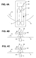
- Fig. 4 shows an embodiment of the permanent magnet 3 and the support 2 in Fig. 1.
- Fig. 4A is a top view of the magneto-optical disc medium 4 seen from the top.
- the permanent magnet 3 is installed in a frame 42 on a rotational axis 43.
- the permanent magnet 3 is forced to revolve around the rotational axis 43 by a stepping motor 41 which is connected to the permanent magnet 3 through the rotational axis 43, and the reproductive magnetic field strength to apply with the magneto-optical disc medium 4 is modified.
- a magnetic sensor 1 is installed in the frame 42 and the sensor identifies a rotating position of the permanent magnet 3 by detecting changes in the magnetic field of the permanent magnet 3.
- the magnetization directions for recording and erasing can be reversed by the rotation of the permanent magnet 3.
- Fig. 4B is a side view of the magneto-optical disc medium seen from the side toward the center of the disc.
- a laser beam 44 is applied from the optical head 5 onto the magneto-optical disc medium 4, and a front mask 45 and a rear mask 46 are formed by the reproductive magnetic field applied with the permanent magnet 3 and then reproduction is carried out.
- the same magnetic field is exerted on the front mask 45 and the rear mask 46.
- Fig. 4C is another side view of the magneto-optical disc medium seen from the side toward the center of the disc.
- the permanent magnet 3 is tilted and the magnetic field exerted on the front mask 45 is greater than that on the rear mask 46.
- a rotary permanent magnet is used as shown in Fig. 4, and optimization of the reproductive magnetic field is achieved by displacing the magnet using rotation. Also, a stronger magnetic field is applied with the front mask side than the rear mask side. In other words, an optimum forming magnetic field for formations of each front mask, rear mask and aperture can be applied respectively. Therefore, a fine aperture can be formed and the reproductive error rate can be lowered. In terms of power consumed by the permanent magnet and the stepping motor, it is more advantageous than using an electromagnet to apply the reproductive magnetic field.
- the permanent magnet can be not only used to apply the reproductive magnetic field but can also be used to apply the magnetic field for recording and erasing, and it can be configured to modify the magnetic field strength for recording and erasing with the drive control method of the permanent magnet used for feedback of the reproductive magnetic field, which is described earlier.
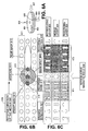
- Fig. 5 shows another embodiment of the permanent magnet 3 and the support 2 in Fig. 1.
- Fig. 5A is a top view of the magneto-optical disc medium 4 seen from the top.
- the permanent magnet 3 mounted on a leaf spring 51 which is installed in a frame 52.
- the leaf spring 51 and the permanent magnet 3 are joined as shown in Fig. 5B.
- an electromagnet for a permanent magnet drive 53 and the leaf spring 51 With an electromagnet for a permanent magnet drive 53 and the leaf spring 51, a horizontal position of the permanent magnet 3 is modified within a range surrounded by the frame 52 and the reproductive magnetic field strength to apply with the magneto-optical disc medium 4 is modified.
- the magnetic sensor 1 is installed in the frame 52 and the sensor identifies a horizontal position of the permanent magnet 3 by detecting changes in the magnetic field of the permanent magnet.
- the magnetization direction can be reversed for recording and erasing with the left side of the permanent magnet 3 being used for recording and the right side for erasing.
- Fig. 5C is a side view of the magneto-optical disc medium seen from the side toward the center of the disc.
- a laser beam 57 is applied from the optical head 5 onto the magneto-optical disc medium 4, and a front mask 55 and a rear mask 56 are formed by the reproductive magnetic field applied with the permanent magnet 3 and then reproduction is carried out.
- a plumb line that runs the center of the beam spot is congruent with a centerline 54 on the left side of the permanent magnet, and the same magnetic field is exerted on the front mask 55 and the rear mask 56.
- Fig. 5D is another side view of the magneto-optical disc medium seen from the side toward the center of the disc.
- the plumb line that runs the center of the beam spot which is located rightward from the centerline 54 of the permanent magnet, and the magnetic field exerted on the front mask is greater than that on the rear mask.
- a horizontally moving permanent magnet is used as shown in Fig. 5, and optimization of the reproductive magnetic field is achieved by displacing the magnet using a horizontal movement. Also, a stronger magnetic field can be applied with the front mask side than the rear mask side. In other words, an optimum forming magnetic field for formations of each front mask, rear mask and aperture and can be applied respectively. Therefore, a fine aperture can be formed and the reproductive error rate can be lowered.
- power consumed by the leaf spring and the electromagnet for the permanent magnet drive, it is more advantageous than using an electromagnet to apply the reproductive magnetic field.
- the permanent magnet can be not only used to apply the reproductive magnetic field but also used to apply the magnetic field for recording and erasing, and it can be configured to modify the magnetic field strength for recording and erasing with the drive control method of the permanent magnet used for feedback of the reproductive magnetic field, which is described earlier.
- the present invention with the information reproducing method of a magneto-optical storage medium, which allows information to be reproduced through applications of the irradiated light intensity and the reproductive magnetic field with a permanent magnet, and a magneto-optical storage apparatus using the reproducing method, information can be reproduced in the optimum reproductive magnetic field while keeping a reproductive error rate under a given order by optimizing the reproductive magnetic field with the irradiated light intensity being set higher than a given intensity.
- the calorific value can be reduced with the use of the permanent magnet as compared to the use of an electromagnet, which in turn can suppress an increase in the reproductive magnetic field strength at a high temperature. Also, by displacing the permanent magnet, a portion of the permanent magnet having the highest magnetic flux density can be efficiently applied to an area that needs the magnetic field most when reproducing.
- the permanent magnet can be of, e.g., a type controlling the magnetic field strength by altering the orientation thereof, or a type controlling the magnetic field strength by altering the horizontal position thereof.
Abstract
A magneto-optical storage apparatus and a
reproducing method are provided. The magneto-optical
storage apparatus is capable of using a magneto-optical
storage medium provided with recording layer and
reproducing layer. In the magneto-optical storage medium,
information in the recording layer is transferred to the
reproducing layer through irradiation of light at a given
intensity for reproduction and through application of a
reproductive magnetic field. The
information contained in a given area thereof is enabled
to be reproduced. The apparatus includes: an optical head
irradiating light to the given area at least at a given
intensity for reproduction; a permanent magnet applying
at least the reproductive magnetic field to the given area;
and a control unit controlling the optical head and the
permanent magnet to reproduce the information,
calculating a reproductive error rate associated with the
reproduction and altering the strength of the reproductive
magnetic field based on the reproductive error rate.
Description
The present invention relates to a reproducing
method of a magneto-optical storage medium that performs
recording and reproducing of information using light and
a magnetic field, and a to magneto-optical storage
apparatus using the reproducing method.
In recent years, the performances of personal
computers have made remarkable improvements. In
accordance with such improvements, the storage capacity
has been growing steadily and an increase in storage
capacity is also being demanded for an external storage
device that is used to exchange data with the outside.
Further, since small, battery-operated and portable
personal computers have also been put to practical use,
a low-power consumption function connectable to such
personal computers is also needed for the external storage
device.
A representative example of the external storage
device is a 3.5-inch magneto-optical disc. Starting with
a product of 128 megabytes (MB) in its storage capacity,
it developed to 230MB, 540MB, 640MB, and then to 1.3
gigabytes (GB), and the storage capacity has now reached
2.3GB. In order to attain a higher capacity, a MSR
(Magnetically induced Super Resolution) medium and a MSR
technology using the MSR medium have been adopted from the
1.3GB products on.
The MSR medium, for example, has three layers: a
reproducing layer, a middle layer and a recording layer,
and binary data is recorded in the recording layer as a
recorded mark which is smaller than a beam spot generated
by a laser beam applied to the medium. When the laser beam
is applied to a rotating magneto-optical disc, areas of
different temperatures are generated within the beam spot,
and when a reproductive magnetic field is applied there,
an area (mask) of the reproducing layer with one
magnetization direction is formed within the beam spot due
to the properties of the MSR medium.
The MSR technology, includes a reproducing method
that masks a given area within a beam spot and enables the
reading of a recorded mark located in an aperture that is
not masked by controlling a laser beam and a reproductive
magnetic field at reproducing. With the use of the MSR
technology, only the recorded mark located within the
aperture can be reproduced even if multiple recorded marks
are contained in the beam spot, and the MSR technology can
also prevent problems such as, a signal from a nearby track
getting crossed into a signal to be reproduced (cross talk).
In addition, a higher capacity has been realized by
reducing the recorded mark size and the distance between
the recorded marks.
However, a greater intensity of a reproductive
magnetic field is sometimes required to reproduce the MSR
medium than to record (to erase) data. For example, when
the medium is placed in an environment that has an operative
temperature of more than 50 degree centigrade, the
reproductive magnetic field strength required is
significantly greater when compared to the medium being
placed in ambient temperature, and to cite a case, a large
reproductive magnetic field, such as more than 350 oersted
(Oe, 1Oe =(1000/4π) A/m, π shows the circle ratio) is
sometimes required. Therefore, a combination of a
irradiated light intensity and the reproductive magnetic
field strength has to be properly selected for optimization
in accordance with an operative temperature. In the
meantime, if π=3.14, 1 oersted is approximately 79.62
ampere/meter.
Also, multiple masks are sometimes formed at
reproducing in the MSR technology. For example, when a
front mask and a rear mask are to be formed at the font
and the rear of the beam in its traveling direction, the
temperature in an area of the front mask side is lower than
that in an area of the rear mask side and the front mask
has a given level of coercive force. In order to arrange
the directions of magnetization into one, the reproductive
magnetic field must be greater than the given coercive
force and the front mask must be applied with the greater
magnetic field than the rear mask. Therefore, coupled
with the optimization described earlier, the balance of
the reproductive magnetic field has to be well controlled.
Further, delicate controls are required to set up the
magnetic field for the reproductive magnetic field and the
size of the magnetic field that the medium receives has
to be also controlled to keep it constant by considering
the balance described above. In addition, considering a
portable external storage device, which is expected to be
predominant in the future, the use of an electromagnet to
generate the reproductive magnetic field is
disadvantageous in terms of power consumption and thus the
use of a permanent magnet is desirable.
Japanese Patent Application Laid-Open Publication No.
2001-176141, the prior application of the inventors of the
application concerned, discloses a method to set up an
optimum reproductive laser power (irradiated light
intensity), however the document does not refer to the
optimization of the reproductive magnetic field strength.
Also, Japanese Patent Application Laid-Open Publication
No. 1999-259925, the prior application of the inventors
of the application concerned, discloses a method to set
the intensities of the reproductive magnetic field and of
the reproductive laser power (irradiated light intensity)
optimally using a super-resolution technology, however
the method is limited to only when a mask is formed on the
front or rear side and thus the document does not refer
to the balance of the reproductive magnetic field
intensities when masks are formed on both front and rear
sides.
International Application No. JP01/04684, the prior
application of the inventors of the application concerned,
presents a magneto-optical storage medium apparatus
characterized by exerting of the stronger magnetic field
on the front mask side than on the rear mask side by means
of moving the peak position of a bias magnetic field to
be applied from the center of the laser beam spot to a given
direction, however the permanent magnet is not used to
apply the reproductive magnetic field thus it is
disadvantageous in terms of power consumption.
Further, International Application No. JP02/00244,
the prior application of the inventors of the application
concerned, proposes a storage apparatus using a permanent
magnet to apply the reproductive magnetic filed, and with
the apparatus, the shape of the permanent magnet is devised
to make the magnetic field strength exerted on the front
mask greater than the reproductive magnetic field
strength; however, the document does not refer to an
optimum combination of the irradiated light intensity and
the reproductive magnetic field strength to reduce a
reproductive error rate.
As another related documents, Japanese Patent
Application Laid-Open Publication No. 1997-204706
discloses a magneto-optical recording and reproducing
apparatus that controls the magnetic field strength to an
optimum value by controlling the position of a permanent
magnet, however the document does not refer to a
reproductive error rate. Further, other related
documents, such as Japanese Patent Application Laid-Open
Publication Nos. 1992-278239, 1993-62276 and 1990-154301
are also available, however none of them are aimed at
optimizing the magnetic field strength and the irradiated
light intensity.
In recognition of the problems described above, the
irradiated light intensity and the reproductive magnetic
field have to be appropriately selected for optimization
in reproducing information using the MSR medium. Also,
when the front mask and the rear mask are used to reproduce,
it is desirable to control the reproductive magnetic field
in such a way that the front mask is applied with a greater
reproductive magnetic field strength than that the rear
mask. Furthermore, it is also desirable to use the
permanent magnet to reduce the power consumption and to
be able to control to maintain the optimized reproductive
magnetic field strength.
In view of the above problems, the object of the
present invention is to provide a magneto-optical disc
apparatus and a method of reproducing information with the
optimized irradiated light intensity and optimized
reproductive magnetic field.
The above object is achieved by the provision of a
magneto-optical storage apparatus capable of using a
magneto-optical storage medium provided with a recording
layer and a reproducing layer. In the magneto-optical
storage medium, information in the recording layer is
transferred to the reproducing layer through irradiation
of light at a given intensity for reproduction and through
application of a reproductive magnetic field. The
information contained in a given area thereof is enabled
to be reproduced. The apparatus includes: an optical head
irradiating light to the given area at least at a given
intensity for reproduction; a permanent magnet applying
at least the reproductive magnetic field to the given area;
and a control unit controlling the optical head and the
permanent magnet to reproduce the information,
calculating a reproductive error rate associated with the
reproduction and altering the strength of the reproductive
magnetic field based on the reproductive error rate.
Preferably, in the magneto-optical storage apparatus
of the present invention, the control unit further alters
the strength of the reproductive magnetic field to a
strength at which a given width for strength changes is
secured within a range of a magnetic field strength where
the reproductive error rate satisfies a given criteria that
enables reproduction.
Preferably, in the magneto-optical storage apparatus
of the present invention, the control unit further alters
the strength of the reproductive magnetic field to a
strength at which the reproductive error rate is minimized
within a range of a magnetic field strength where the
reproductive error rate satisfies a given criteria that
enables reproduction.
Preferably, the magneto-optical storage apparatus of
the present invention further includes a magnetic sensor
measuring the magnetic field strength of the permanent
magnet, wherein the control unit further controls the
permanent magnet to keep the magnetic field strength
measured by the magnetic sensor at the altered reproductive
magnetic field strength.
Preferably, the magneto-optical storage apparatus of
the present invention further includes unit measuring the
distance between the optical head and the magneto-optical
storage medium, wherein the control unit further controls
the permanent magnet to keep the altered reproductive
magnetic field strength in response to the measured
distance.
Preferably, in the magneto-optical storage apparatus
of the present invention, the permanent magnet is rotatable
around a rotational axis, and the control unit controls
the permanent magnet by altering the angle of the permanent
magnet.
Preferably, in the magneto-optical storage apparatus
of the present invention, the permanent magnet is
displaceable in a horizontal direction parallel to the
magneto-optical storage medium, and the control unit
controls the permanent magnet by altering the horizontal
position of the permanent magnet.
The above object is achieved by the provision of
reproducing method of a magneto-optical storage medium
provided with a recording layer and a reproducing layer.
In the magneto-optical storage medium, information in the
recording layer is transferred to the reproducing layer
through irradiation of light at a given intensity for
reproduction and through application of a reproductive
magnetic field. The information contained in a given area
thereof is enabled to be reproduced. The method includes
the steps of: irradiating light for reproduction to the
given area; applying the reproductive magnetic field to
the given area by a permanent magnet; reproducing the
information by use of the irradiation light and the
reproductive magnetic field; calculating a reproductive
error rate associated with the reproduction; and altering
the strength of the reproductive magnetic field to be
applied by the permanent magnet, based on the reproductive
error rate.
According to an embodiment of the present invention,
with the information reproducing method of a
magneto-optical storage medium, which allows information
to be reproduced through applications of the irradiated
light intensity and the reproductive magnetic field with
a permanent magnet, and the magneto-optical storage
apparatus using the reproducing method, information can
be reproduced in the optimum reproductive magnetic field
while keeping the reproductive error rate below a given
order by optimizing the reproductive magnetic field
strength with the irradiated light intensity being set
higher than a given intensity.
Further, according to another embodiment, with the
information reproducing method of a magneto-optical
storage medium, which allows information to be reproduced
through applications of the irradiated light intensity and
the reproductive magnetic field with a permanent magnet,
and a magneto-optical storage apparatus using the
reproducing method, the calorific value can be reduced
with the use of the permanent magnet as compared to an
electromagnet, which in turn can suppress an increase in
the reproductive magnetic field strength at a high
temperature. Also, by displacing the permanent magnet,
a portion having the highest magnetic flux density of the
permanent magnet can be efficiently applied to an area that
needs the magnetic field most when reproducing. For a
permanent magnet, the one that controls the magnetic field
strength by changing the orientation, the one by changing
a horizontal position and so forth can be used.
Also, according to a further embodiment, with the
information reproducing method of a magneto-optical
storage medium, which allows information to be reproduced
through applications of the irradiated light intensity and
the reproductive magnetic field with a permanent magnet,
and a magneto-optical storage apparatus using the
reproducing method, signals can be reproduced in a more
stabilized manner with a feedback control, which
constantly monitors the intensity of the magnetic field
and controls to keep the monitoring signals steady, even
if the reproductive magnetic field strength fluctuates due
to vibrations that the apparatus receives.
Also, according to yet another embodiment, with the
information reproducing method of a magneto-optical
storage medium, which allows information to be reproduced
through applications of the irradiated light intensity and
the reproductive magnetic field with a permanent magnet,
and a magneto-optical storage apparatus using the
reproducing method, a focus servo control circuit is
provided to monitor the distance between the
magneto-optical storage medium and an optical head to keep
the intensity of the magnetic field that the medium
receives constantly stable. By controlling the
reproductive magnetic field strength according to the
changes in distance, stable recording, reproduction and
erasing become possible because the magnetic field that
the medium receives due to vibrations of the medium surface
doesn't change. Also, according to other embodiment, with
the information reproducing method of a magneto-optical
storage medium, which allows information to be reproduced
through applications of the irradiated light intensity and
the reproductive magnetic field with a permanent magnet,
and a magneto-optical storage apparatus using the
reproducing method, even if the distribution of the
reproductive error rate changes due to a rise in the
operative temperature of the magneto-optical storage
apparatus, the reproductive magnetic field can be set to
optimum in accordance with the change.
In the following, modes for carrying out the present
invention are described by drawings. However, the
technical scope of the present invention is not to be
limited to embodiments but it is to cover the present
invention described in the claim as well as its
equivalents.
First, recording of information with a
magneto-optical disc apparatus using a MSR medium, which
is the premise of the present invention, is explained. The
MSR medium of DRAD (Double Mask Rear Aperture Detection)
method is used to explain here. Fig. 6 describes an
existing information reproducing. Fig. 6A describes the
way of a laser beaming at a magneto-optical disc medium.
In Fig. 6A, the magneto-optical disc medium 601 rotates
in an anticlockwise direction 602. A laser beam 604 from
an optical head 603 is applied to the magneto-optical disc
medium 601 and a beam spot 605 is formed on the medium.
Fig. 6B is a top view of the magneto-optical disc
medium 601 seen from a vertical direction 606 in Fig. 6A
against the magneto-optical disc medium. A portion of the
magneto-optical disc medium 601 is excerpted. Many tracks
617 exist on the magneto-optical disc medium 601 and
information is recorded on the tracks as a recorded mark
615. The recorded mark 615 is in a recording layer 625
to be described and the mark is transferred to a reproducing
layer 623 to be also described and reproduced.
Fig. 6B shows a state of a front mask 611, an aperture
612 and a rear mask 613 being formed within the beam spot
605. In Fig. 6B the recorded mark is included in the beam
spot 605. The front mask, the rear mask and the aperture
will be described later. If the rotation of the medium
is stopped, the beam spot 605 appears as if to proceed to
a direction 618, which is opposite the rotation direction
602 of the medium. To the beam spot 605, a beam's seeming
traveling direction side 618 is called front and a side
of the medium's rotating direction 602 is called rear. The
front mask is not shown but is spread across the front,
and a recorded mark 614 is located in the front mask 611,
a recorded mark 615 in the aperture 612 and a recorded mark
616 in the rear mask 613 in Fig. 6B.
Fig. 6C is a sectional view of a middle track in Fig.
6 when the magneto-optical disc medium 601 is seen from
a lateral direction 607 in Fig. 6A. The magneto-optical
disc medium 601 using the MSR medium includes of a
reproducing layer 623, a middle layer 624 and a recording
layer 625. In the recording layer 625, information is
recorded as a recorded mark using magnetization of a
recording direction 622 and an erasing direction 621 that
face against each other in order to record binary data of
0 and 1. In Fig. 6C, an upward arrow is represented by
the recording direction 622 and a downward arrow by the
erasing direction 621.
The three layers have the following properties.
First, concerning coercive force, the recording layer 625
has higher coercive force than the other two layers at
ambient temperature. Next, concerning switched connection
force, the switched connection force of the reproducing
layer 623 and the middle layer 624 is strong at ambient
temperature and magnetization directions of these two
layers go against each other. At a given temperature, the
switched connection of the recording layer 625, the middle
layer 624 and the reproducing layer 623 become stronger.
As a result, at the given temperature, information in the
recording layer is to be transferred to the reproducing
layer. Further, at a temperature higher than the given
temperature, the reproducing layer 623 and the middle layer
624 have a property to lose the switched connection between
them.
In addition, concerning effects on the reproductive
magnetic field, the middle layer 624 is more susceptible
to receiving effects of the reproductive magnetic field
than the reproducing layer 623 is at ambient temperature,
and the middle layer is magnetized to the same direction
as the reproductive magnetic field. Then the reproducing
layer is magnetized to the opposite by the switched
connection. Also, at a temperature at which the switched
connection of the reproducing layer 623 and the middle
layer 624 is lost, the reproducing layer is affected by
the reproductive magnetic field and becomes magnetized in
the same direction as the reproductive magnetic field.
The temperature that the recording layer is affected by
the reproductive magnetic field is higher than the
temperature at which the switched connection of the
reproducing layer 623 and the middle layer 624 is lost,
thus the recording layer is not affected by the
reproductive magnetic field at the temperature of which
the switched connection of the reproducing layer 623 and
the middle layer 624 is lost.
Next, the way of reproducing information in the
recording layer 625 is explained with reference to Fig.
6B and Fig. 6C. When the laser beam 604 is applied to the
rotating magneto-optical disc medium 601, the beam spot
605 is formed and the temperature of a recorded mark within
the beam spot 605 rises. Since the magneto-optical disc
medium 601 moves as it rotates, differences in temperature
occur within the beam spot 605 due to differences in the
amount of time applied with the laser beam.
The time applied with the laser beam is short for the
recorded mark 614 in Fig. 6C and thus has the lowest
temperature in the beam spot 605. A temperature of the
recorded mark 615 in the center of the beam spot 605 is
higher than that of the recorded mark 614. Also, the time
applied with the laser beam is longer for the recorded mark
616 than for the other recorded marks in the beam spot 605
and thus its temperature is higher than that of the recorded
mark 615.
At any given time, application of the laser beam is
controlled so that the recorded mark 614 becomes at ambient
temperature, the recorded mark 615 at the given temperature
of which the transfer from the recording layer 625 to the
reproducing layer 623 takes place, and the recorded mark
616 at the temperature of the switched connection of the
reproducing layer 623 and the middle layer 622 becomes lost.
The reproductive magnetic field 626 that is in the same
direction as the recording direction 622 is applied here.
Having done this, due to the properties of the three
layers, the middle layer 624 is magnetized into the
recording direction 622 at the position of the recorded
mark 614, and the reproducing layer 623 becomes magnetized
into the erasing direction 621 by the switched connection.
At the position of the recorded mark 615, information in
the recording layer 625 is transferred to the reproducing
layer 623. At the position of the recorded mark 616, the
reproducing layer 623 is magnetized into the recording
direction.
Although not shown, receiving the effects of the
reproductive magnetic field, an area that has the same
magnetization direction as the recorded mark 614 is formed
at the recorded mark on the front side. Likewise, an area
that has the same magnetization direction as the recorded
mark 616 is formed at the recorded mark on the rear side.
They are the front mask 611 and the rear mask 613
respectively.
As described above, the front mask 611, which is
magnetized into the direction opposite from that of the
reproductive magnetic field 626 (the erasing direction 621
in Fig. 6C), is formed in the front side of the reproducing
layer 623, and the rear mask 613, which is magnetized into
the same direction as that of the reproductive magnetic
field 626 (the recording direction 622 in Fig. 6C), is
formed in the rear side of the reproducing layer 623. In
Fig. 6C, the oval shaped rear mask 613 is formed on the
rear side by the rotation of the magneto-optical disc
medium 616 and thermal diffusion, and the crescent-shaped
aperture 612 is formed from the beam spot 605, which is
not covered by neither the front mask 611 nor the rear mask
613.
Since the magnetization directions of the front mask
611 and the rear mask 613 are opposite, the magnetization
direction of the recording layer, which has been
transferred to the reproducing layer at the position of
the recorded mark 615, determines the direction of
magnetization included in reflected lights from the beam
spot 605. Therefore, by analyzing the reflected lights
from the beam spot 605, the recorded mark 615 is accurately
reproduced though it is smaller than the beam spot 605.
However, with the existing magneto-optical disc
apparatus, the irradiated light intensity and the
reproductive magnetic field are not optimized and so
consuming more power than necessary has been a problem.
Also, even with the magneto-optical disc apparatus for
which the irradiated light intensity and the reproductive
magnetic field are optimized, problems remain, such as an
electromagnet that consumes a large amount of power is used
to apply the reproductive magnetic field with no
consideration to a balance between the magnetic field
intensities exerted on the front mask, which requires a
greater reproductive magnetic field than the rear mask does,
and the rear mask, and thus leave room for further
improvements.
Given such circumstances, the magneto-optical disc
apparatus, which enables the MSR medium to be reproduced
upon optimizing the intensities of the laser beam and of
the reproductive magnetic field to be applied, and the
reproducing method will be described in a mode for
carrying out the present invention. Also, concerning
optimization, the magneto-optical disc apparatus with
which the magnetic field is set to exert higher intensity
on the front mask, which requires the stronger reproductive
magnetic field, than on the rear mask will be described
along with the reproducing method. To apply various
magnetic fields (recording, erasing or reproduction), the
permanent magnet is used to lower the power consumption
for the overall apparatus.
Fig. 1 shows a configuration example of an embodiment
of the magneto-optical disc apparatus of the present
invention. The magneto-optical disc apparatus records
information onto the magneto-optical disc medium and
reproduces the recorded information using light and
magnetism. Fig. 1A especially shows devices and circuits
associated mainly with reproducing of the magneto-optical
disc medium 4, of the magneto-optical disk apparatus, with
the magneto-optical disc medium 4 and an optical head 5
being viewed from a direction 14 in Fig. 1B. The
magneto-optical disc medium is connected to a terminal such
as a computer through an interface not shown in control
unit 12, and an instruction to record or reproduce and
information from the terminal are transmitted to and from
the control unit 12.
The magneto-optical disc medium 4 is forced to
rotate in a rotating direction 13 by a spindle motor 6.
The rotating magneto-optical disc medium is applied with
the laser beam from the optical head 5 and then is applied
with the magnetic field by the permanent magnet 3 to carry
out recording and reproducing of information. An MSR
medium is used as the magneto-optical disc medium 4.
The permanent magnet 3 is supported by a support unit
2 and is displaced by a permanent magnet drive control
circuit 8. By displacing the permanent magnet 3, the
magnetic field strength to apply the magneto-optical disc
medium 4 can be appropriately modified. As an example,
a bar-shaped permanent magnet that revolves around an axis
is drawn in Fig. 1A and the position and the magnetic field
strength is modified through controlling the rotation of
the axis.
A magnetic sensor 1 detects the magnetic field
strength of the permanent magnet 3. The sensor is used
to monitor the magnetic field strength to be applied with
and any fluctuations in the magnetic field strength due
to vibrations of the apparatus. A focus servo control
circuit 9 controls the intensity of the laser beam to be
applied with and monitors the distance between the
magneto-optical disc medium 4 and the optical head 5. If
the distance between the optical head 5 and the
magneto-optical disc medium 4 fluctuates due to vibrations
of the magneto-optical disc apparatus or of the
magneto-optical disc medium surface, the distance between
the permanent magnet 3 and the magneto-optical disc medium
4 is also modified and the feedback control is carried out
to maintain the reproductive magnetic field strength
properly in conjunction with the control unit 12 to be
described later.
A read-write control circuit 10 moves the optical
head 5 to a given address on the magneto-optical disc medium
4 to be recorded or reproduced and controls sending and
receiving of information to be recorded or reproduced. A
spindle motor control circuit 11 controls the rotation of
the spindle motor 6.
The control unit 12 stores a CPU that carries out
overall control over the magneto-optical disc apparatus
not shown along with computed results and setups done in
the CPU, and the unit also has a memory not shown that stores
programs to control the CPU. The control unit 12 issues
control instructions to a magnetic field sensor circuit
7, the permanent magnet drive control circuit 8, the focus
servo control circuit 9, the read-write control circuit
10, and the spindle motor control circuit 11. For example,
if the magnetic field sensor circuit 7 has detected that
the magnetic field strength has fluctuated from the optimum
one, the control unit 12 will instruct the permanent magnet
drive control circuit 8 to move the permanent magnet 3 to
a position where the optimum magnetic field strength can
be maintained.
Further, if the focus servo control circuit 9 has
detected that the distance between the optical head 5 and
the magneto-optical disc medium 4 has fluctuated, which
means that the distance between the permanent magnet 3 and
the magneto-optical disc medium 4 has also fluctuated, the
control unit will instruct the permanent magnet drive
control circuit 8 to move the permanent magnet 3 to a
position where a magnetic field strength necessary for each
operation of recording, erasing or reproducing
information can be maintained.
Subsequently to a configuration example of the
magneto-optical disc apparatus of the present invention
described above, an embodiment of an information
reproducing method of the present invention using the
magneto-optical disc apparatus in Fig. 1 will be explained
with reference to Fig. 2 and Fig. 3. The method of
reproducing information in the present invention is to
control the reproductive magnetic field and the laser beam
a magnetic field strength and a irradiated light intensity
decided respectively based on a process to determine the
optimum magnetic field strength shown in Fig. 2 to optimize
the reproductive magnetic field. An example diagram in
Fig. 3 shows the distribution of bit error rates
(reproductive error rates) in reproducing information
according to combinations of the reproductive magnetic
field strength and the irradiated light intensity.
Fig. 2 is a flowchart that explains the process to
determine the optimum magnetic field strength. First, the
irradiated light intensity is set at an initial value (S21).
A given value is set as the initial value for the irradiated
light intensity. For example, having pre-recorded a given
value in the memory in the control unit 12, the control
unit 12 instructs the focus servo control circuit 9 to
irradiate the laser beam at the given intensity based on
the given value read out of the memory. The focus servo
control circuit 9 controls the irradiated light intensity
of the optical head 5 based on the instruction received
from the control unit 12.
Using Fig. 3, an example will be given here to explain
a method to determine an initial value for the irradiated
light intensity in a step S31. An example diagram in Fig.
3 shows the distribution of the bit error rates
(reproductive error rates) in reproducing information
according to combinations of the reproductive magnetic
field strength and the irradiated light intensity. The
vertical axis shows the irradiated light intensity and the
horizontal axis the reproductive magnetic field strength,
and the reproductive error rate that corresponds to a
combination of the two intensities is drawn into the
diagram. The example shows that reproducing is performed
more accurately if the reproductive error rate is lower,
and reproducing has to be carried out with the reproductive
error rate being in an order of 10 to the -5th power for
a reproduction standard of the apparatus here.
In Fig. 3, the reproductive error rates are: an order
of 10 to the -1st power for an area 31 labeled as -1 to
0,; of 10 to the -2nd power for an area 32 labeled as -2
to -1; of 10 to the -3rd power for an area 33 labeled as
-3 to -2; of 10 to the -4th power for an area 34 labeled
as -4 to -3; and of 10 to the -5th power for an area 35
labeled as -5 to -4.
Among these areas, the area 35 is called a
reproducible area and it is important to select the
irradiated light intensity and the reproductive magnetic
field strength in such an order of 10 to the -5th power
for the reproductive error rate. In Fig. 3, for example,
when the irradiated light intensity is fixed at 3.5
milliwatt (mW), a selectable range for the reproductive
magnetic field that allows reproduction is approximately
between 300 and 400oersted (Oe, 10e =(1000/4π) A/m),
however when the irradiated light intensity is raised to
4mW, the selectable range expands to approximately between
170 and 380Oe (Oe, 1Oe =(1000/4π) A/m) and thus we can
see that the magnetic field strength as strong as that for
3.5mW is not necessarily required.
Further, when the irradiated light intensity is
higher than a given intensity (4mW or higher in Fig. 3),
the selectable range for the reproductive magnetic field
that allows reproduction becomes almost constant (the
range that includes the following: approximately between
200 and 375Oe (Oe, 1Oe =(1000/4π) A/m)). In the
specification, the lower bound of the irradiated light
intensity such as above is called the smallest reproductive
power. In terms of this distribution characteristic, the
smallest reproductive power differs depending on
materials used for the magneto-optical disc medium,
however if materials of the magneto-optical disc medium
can be identified, the smallest reproductive power can be
also identified.
Therefore, the initial value for the irradiated light
intensity is set to the smallest reproductive power.
Since the smallest reproductive power can be identified
if a magneto-optical disc medium is specified, the control
unit 12 is to read out the smallest reproductive power of
a corresponding magneto-optical disc medium in the memory
(not shown) which records the smallest reproductive power
for each magneto-optical disc medium in the control unit
12. Another way to determine the initial value of the
irradiated light intensity is to use a given value that
has been set without specifying a magneto-optical disc
medium and then to modify the irradiated light intensity
later.
Reference is again made to Fig. 2 to continue the
explanation. Next, the reproductive magnetic field is set
to an initial value (S22). A given value is set as an
initial value for the reproductive magnetic field strength.
For example, having pre-recorded a given value in the
memory (not shown) in the control unit 12, the control unit
12 instructs the permanent magnet drive control circuit
8 to displace the position of the permanent magnet 3 to
where it can achieve the magnetic field strength based on
the given value read out of the memory. As an initial value,
for example, a value of 1500Oe (Oe, 1Oe =(1000/4π) A/m)
is good to set. The permanent magnet drive control circuit
8 drives the permanent magnet 3 based on the instructions
received from the control unit 12.
Then, with a combination of the irradiated light
intensity and the optimum magnetic field strength
determined in the steps S21 and S22, information is
reproduced and the reproductive error rate that is involved
in reproduction is calculated (S23). The control unit 12
instructs the read-write control circuit 10 to execute
reproducing of information. The read-write control
circuit 10 moves the optical head 5 to a position on the
magneto-optical disc medium that is recorded with
information to be reproduced, reproduces the information
and sends the information regarding the occurrence of a
reproductive error to the control unit 12. Based on the
error information, the control unit can obtain a
reproductive error rate.
For example, as one of the methods to obtain the
reproductive error rates, the control unit 12 first creates
a test pattern and then stores it in the memory, which has
not been illustrated. Then the unit erases the
information on the sector subject to testing on a test track
set up in a given area of the storage medium. After the
information in the sector subjected to testing is erased,
the test pattern stored in the buffer memory is recorded
in the sector subjected to testing.
After recording the test pattern into the sector
subject to testing, the control unit 12 sets the irradiated
light intensity for the laser spot and the magnetic field
strength to the values obtained at the steps S21 and S22,
and reproduces the test pattern from the sector subject
to testing. Then the test pattern reproduced is compared
to the original one stored in the memory and the bit error
rates in reproduction (reproductive error rates) is
calculated and stored in the memory in the control unit
that is not shown. By repeating this procedure as the
magnetic field strength is modified, for example, a
magnetic field strength with the lowest reproductive error
rate can be obtained.
Next, while the irradiated light intensity specified
in the step S21 is maintained, the permanent magnet 3 is
displaced and information is reproduced with a newly set
reproductive magnetic field strength to calculate the
reproductive error rate involved in reproduction (S24).
The displacement of the permanent magnet and calculation
of the error rates are the same as the step S22 and S23.
How the permanent magnet is displaced differs depending
on the magneto-optical disc apparatus and the shape of the
permanent magnet provided. Rotating the permanent magnet,
changing its horizontal position and such are some of the
examples.
Then, the step S24 is repeated until the given
conditions are satisfied (S25). For example, if it is a
permanent magnet that takes the form of a rotational axis,
a given condition is to repeat the step until the
calculation of a reproductive error rate for one rotation
is complete. Further, if it is a permanent magnet that
takes the form of moving horizontally, calculation of a
reproductive error rate is repeated until the magnet fully
travels its operating range in the horizontal position.
As another example, the calculation can be also repeated
till the upper and lower bounds of the reproductive
magnetic field strength that satisfy the conditions for
the reproducible area are found. Or, having the number
of observation points for the reproductive error rates
specified, calculation of the reproductive error rates can
be repeated until more than the number specified are
measured. Also, the following method can be also used:
reproduction is carried out with a newly set irradiated
light intensity, which has been changed from the smallest
reproductive power specified in the step S21, and the
reproductive error rates are compared to decide a superior
irradiated light intensity of the two for use and then the
steps S22 and S23 are to be worked over.
Once the distribution of the reproductive error rates
has been calculated for which the reproductive magnetic
intensity is modified keeping the irradiated light
intensity set in the step S21, an optimum value is
determined from the range of the magnetic field strength
that satisfies the criteria for which the reproductive
error rate calculated can be included in the reproducible
area (S26). One way to determine an optimum value is to
choose a magnetic field strength with the lowest
reproductive error rate in the reproducible area. For
example, if the irradiated light intensity of 4mW is chosen
as an initial value for the irradiated light intensity in
the step S21, the range of the reproductive magnetic field
included in the reproducible area is approximately between
175 and 380Oe (Oe, 1Oe =(1000/4π) A/m) in the example in
Fig. 3. If the lowest reproductive error rate within this
range is 250Oe (Oe, 1Oe = (1000/4π) A/m), the 250Oe is to
be chosen for the reproductive magnetic field strength.
The reproductive error rate becomes higher when the
front mask and the rear mask are not formed properly.
Especially, as described earlier, the front mask requires
a higher reproductive magnetic field strength, thus if the
magnetic field applied to the front mask is weak, cross
talk will take place and the reproductive error rate rises.
In other words, when a reproductive magnetic field with
the lowest reproductive error rate is chosen, a condition
of having the front mask being applied with a stronger
forming magnetic field than the rear mask can be created.
However, whether or not the front mask requires a stronger
forming magnetic field than the rear mask does is dependent
on the materials in the medium coating structure and thus
the rear mask may require a stronger forming magnetic field
than the front mask does depending on coating structures.
The control for such a case is the opposite of the one with
the front mask needing a stronger forming magnetic field
than the rear mask.
Further, when the temperature of the medium in the
stationary condition (before the laser beam is applied)
rises in accordance with an increase in the operative
temperature of the magneto-optical disc apparatus, the
distribution in Fig. 3 moves toward the right as a whole
and the range of the reproductive magnetic field strength
required at a given irradiated light intensity shifts
further toward the higher end of the magnetic field
strength. However even in this case, the method to
determine the reproductive magnetic field strength with
the smallest reproductive error rate above can be applied.
Another example of determining the optimum value in
the step S26 is to choose the lowest value that allows for
sufficient margins from the range between the upper and
lower bounds of the magnetic field that satisfies the
criteria for the reproducible area. For example, if the
irradiated light intensity of 4mW is chosen as an initial
value for the irradiated light intensity in the step S21,
the upper and lower bounds of the reproductive magnetic
field strength that is reproducible are 175Oe and 380Oe
(Oe, 1Oe = (1000/4π) A/m) respectively in the example given
in Fig. 3.
Even if the magnetic field strength that the
magneto-optical disc medium receives has fluctuated due
to vibrations of the permanent magnet or is affected by
vibrations of the magneto-optical disc apparatus being
used or of the surface of the magneto-optical disc medium,
sufficient margins to be included in the reproducible area
are secured steady and so, for example, the optimum
reproductive magnetic field strength may be decided as
275Oe (Oe, 1Oe=(1000/4π) A/m) . If it is an apparatus that
is less affected by vibrations of the permanent magnet or
of the surface of the magneto-optical disc medium, margins
required are smaller thus lower values can be set.
Also, when the temperature of the medium in the
stationary condition (before the laser beam is applied)
rises in accordance with an increase in the operative
temperature of the magneto-optical disc apparatus, the
distribution in Fig. 3 moves toward the right as a whole
and the range of the reproductive magnetic field strength
required at a given irradiated light intensity shifts
further toward the higher end of the magnetic field
strength. However even in this case, the method to
determine the reproductive magnetic field strength that
measures the upper and lower bounds of the reproducible
reproductive magnetic field strength can be applied.
As for when to carry out the process to determine the
magnetic field strength, for example, it can be carried
out when the storage medium is inserted, once every
specified time, when a recording or reproductive command
is issued for the first time after inserting the medium,
at retrying after an error, at a temperature change and
so forth.
Also, if the information reproducing method is
stored as a program in the memory of the control unit 12,
it can be executed as a magneto-optical disc apparatus to
reproduce the MSR medium with the optimized irradiated
light intensity and reproductive magnetic field strength.
Using the information reproducing method of the
present invention as well as the magneto-optical disc
apparatus that employs the information reproducing
method described above, information can be reproduced in
the optimum reproductive magnetic field while keeping the
reproductive error rate under a given order. To keep the
error rate under a given order, the reproductive magnetic
field is modified with the irradiated light intensity being
set higher than a given intensity and then the optimum
reproductive magnetic field is set based on the
reproductive error rates obtained. Also, by choosing a
reproductive magnetic field that has the smallest
reproductive error rate in the reproducible area, a
stronger magnetic field can be applied to the front mask
than to the rear mask.
Further, even if the reproductive magnetic field has
fluctuated, stable reproduction can be carried out by
choosing values that allows for the securing of sufficient
margins from the reproductive magnetic field between the
upper and lower bounds of the reproducible area.
Additionally, even if the distribution of the reproductive
error rates changes due to an increase in the operative
temperature of the magneto-optical disc apparatus, the
optimum reproductive magnetic field strength can be set
in accordance with the change.
An embodiment of the information reproducing method
of the present invention and an embodiment of the
magneto-optical disc apparatus that employs the
reproducing method have been described above, and
subsequently, embodiments of the permanent magnet 3 and
a support 4 will be explained to illustrate fluctuations
of the reproductive magnetic field in the magneto-optical
disc apparatus as well as a condition of which the
reproductive magnetic field is applied with the masks.
Fig. 4 shows an embodiment of the permanent magnet
3 and the support 2 in Fig. 1. Fig. 4A is a top view of
the magneto-optical disc medium 4 seen from the top. In
Fig. 4A, the permanent magnet 3 is installed in a frame
42 on a rotational axis 43. The permanent magnet 3 is
forced to revolve around the rotational axis 43 by a
stepping motor 41 which is connected to the permanent
magnet 3 through the rotational axis 43, and the
reproductive magnetic field strength to apply with the
magneto-optical disc medium 4 is modified.
A magnetic sensor 1 is installed in the frame 42 and
the sensor identifies a rotating position of the permanent
magnet 3 by detecting changes in the magnetic field of the
permanent magnet 3. The magnetization directions for
recording and erasing can be reversed by the rotation of
the permanent magnet 3.
Fig. 4B is a side view of the magneto-optical disc
medium seen from the side toward the center of the disc.
A laser beam 44 is applied from the optical head 5 onto
the magneto-optical disc medium 4, and a front mask 45 and
a rear mask 46 are formed by the reproductive magnetic field
applied with the permanent magnet 3 and then reproduction
is carried out. In a condition in Fig. 4B, the same
magnetic field is exerted on the front mask 45 and the rear
mask 46.
Fig. 4C is another side view of the magneto-optical
disc medium seen from the side toward the center of the
disc. In Fig. 4C, the permanent magnet 3 is tilted and
the magnetic field exerted on the front mask 45 is greater
than that on the rear mask 46.
With the magneto-optical disc medium of the present
invention, a rotary permanent magnet is used as shown in
Fig. 4, and optimization of the reproductive magnetic field
is achieved by displacing the magnet using rotation. Also,
a stronger magnetic field is applied with the front mask
side than the rear mask side. In other words, an optimum
forming magnetic field for formations of each front mask,
rear mask and aperture can be applied respectively.
Therefore, a fine aperture can be formed and the
reproductive error rate can be lowered. In terms of power
consumed by the permanent magnet and the stepping motor,
it is more advantageous than using an electromagnet to
apply the reproductive magnetic field.
Further, the permanent magnet can be not only used
to apply the reproductive magnetic field but can also be
used to apply the magnetic field for recording and erasing,
and it can be configured to modify the magnetic field
strength for recording and erasing with the drive control
method of the permanent magnet used for feedback of the
reproductive magnetic field, which is described earlier.
Fig. 5 shows another embodiment of the permanent
magnet 3 and the support 2 in Fig. 1. Fig. 5A is a top
view of the magneto-optical disc medium 4 seen from the
top. In Fig. 5A, the permanent magnet 3 mounted on a leaf
spring 51 which is installed in a frame 52. The leaf spring
51 and the permanent magnet 3 are joined as shown in Fig.
5B. With an electromagnet for a permanent magnet drive
53 and the leaf spring 51, a horizontal position of the
permanent magnet 3 is modified within a range surrounded
by the frame 52 and the reproductive magnetic field
strength to apply with the magneto-optical disc medium 4
is modified.
The magnetic sensor 1 is installed in the frame 52
and the sensor identifies a horizontal position of the
permanent magnet 3 by detecting changes in the magnetic
field of the permanent magnet. By placing permanent
magnets side by side with their poles facing differently
from each other, for example, the magnetization direction
can be reversed for recording and erasing with the left
side of the permanent magnet 3 being used for recording
and the right side for erasing.
Fig. 5C is a side view of the magneto-optical disc
medium seen from the side toward the center of the disc.
A laser beam 57 is applied from the optical head 5 onto
the magneto-optical disc medium 4, and a front mask 55 and
a rear mask 56 are formed by the reproductive magnetic field
applied with the permanent magnet 3 and then reproduction
is carried out. In Fig. 5C, a plumb line that runs the
center of the beam spot is congruent with a centerline 54
on the left side of the permanent magnet, and the same
magnetic field is exerted on the front mask 55 and the rear
mask 56.
Fig. 5D is another side view of the magneto-optical
disc medium seen from the side toward the center of the
disc. In Fig. 5D, the plumb line that runs the center of
the beam spot which is located rightward from the
centerline 54 of the permanent magnet, and the magnetic
field exerted on the front mask is greater than that on
the rear mask.
With the magneto-optical disc medium of the present
invention, a horizontally moving permanent magnet is used
as shown in Fig. 5, and optimization of the reproductive
magnetic field is achieved by displacing the magnet using
a horizontal movement. Also, a stronger magnetic field
can be applied with the front mask side than the rear mask
side. In other words, an optimum forming magnetic field
for formations of each front mask, rear mask and aperture
and can be applied respectively. Therefore, a fine
aperture can be formed and the reproductive error rate can
be lowered. In terms of power consumed by In terms of power
consumed by the permanent magnet, the leaf spring and the
electromagnet for the permanent magnet drive, it is more
advantageous than using an electromagnet to apply the
reproductive magnetic field.
Furthermore, the permanent magnet can be not only
used to apply the reproductive magnetic field but also used
to apply the magnetic field for recording and erasing, and
it can be configured to modify the magnetic field strength
for recording and erasing with the drive control method
of the permanent magnet used for feedback of the
reproductive magnetic field, which is described earlier.
As described above, through the present invention,
with the information reproducing method of a
magneto-optical storage medium, which allows information
to be reproduced through applications of the irradiated
light intensity and the reproductive magnetic field with
a permanent magnet, and a magneto-optical storage
apparatus using the reproducing method, information can
be reproduced in the optimum reproductive magnetic field
while keeping a reproductive error rate under a given order
by optimizing the reproductive magnetic field with the
irradiated light intensity being set higher than a given
intensity.
Further, The calorific value can be reduced with the
use of the permanent magnet as compared to the use of an
electromagnet, which in turn can suppress an increase in
the reproductive magnetic field strength at a high
temperature. Also, by displacing the permanent magnet,
a portion of the permanent magnet having the highest
magnetic flux density can be efficiently applied to an area
that needs the magnetic field most when reproducing. The
permanent magnet can be of, e.g., a type controlling the
magnetic field strength by altering the orientation
thereof, or a type controlling the magnetic field strength
by altering the horizontal position thereof.
Claims (14)
- A magneto-optical storage apparatus capable of using a magneto-optical storage medium provided with a recording layer and a reproducing layer, in the magneto-optical storage medium, information in the recording layer being transferred to the reproducing layer through irradiation of light at a given intensity for reproduction and through application of a reproductive magnetic field, and the information contained in a given area thereof being enabled to be reproduced, the apparatus comprising:an optical head irradiating light to the given area at least at a given intensity for reproduction;a permanent magnet applying at least the reproductive magnetic field to the given area; anda control unit controlling the optical head and the permanent magnet to reproduce the information, calculating a reproductive error rate associated with the reproduction and altering the strength of the reproductive magnetic field based on the reproductive error rate.
- The magneto-optical storage apparatus of claim 1, wherein
the control unit further alters the strength of the reproductive magnetic field to a strength at which a given width for strength changes is secured within a range of a magnetic field strength where the reproductive error rate satisfies a given criteria that enables reproduction. - The magneto-optical storage apparatus of claim 1, wherein
the control unit further alters the strength of the reproductive magnetic field to a strength at which the reproductive error rate is minimized within a range of a magnetic field strength where the reproductive error rate satisfies a given criteria that enables reproduction. - The magneto-optical storage apparatus of claim 1, further comprising a magnetic sensor measuring the magnetic field strength of the permanent magnet, wherein the control unit further controls the permanent magnet to keep the magnetic field strength measured by the magnetic sensor at the altered reproductive magnetic field strength.
- The magneto-optical storage apparatus of claim 1, further comprising unit measuring the distance between the optical head and the magneto-optical storage medium, wherein the control unit further controls the permanent magnet to keep the altered reproductive magnetic field strength in response to the measured distance.
- The magneto-optical storage apparatus of claim 1, wherein
the permanent magnet is rotatable around a rotational axis, and wherein
the control unit controls the permanent magnet by altering the angle of the permanent magnet. - The magneto-optical storage apparatus of claim 1, wherein
the permanent magnet is displaceable in a horizontal direction parallel to the magneto-optical storage medium, and wherein
the control unit controls the permanent magnet by altering the horizontal position of the permanent magnet. - A reproducing method of a magneto-optical storage medium provided with a recording layer and a reproducing layer, in the magneto-optical storage medium, information in the recording layer being transferred to the reproducing layer through irradiation of light at a given intensity for reproduction and through application of a reproductive magnetic field, and the information contained in a given area thereof being enabled to be reproduced, the method comprising the steps of:irradiating light for reproduction to the given area;applying the reproductive magnetic field to the given area by a permanent magnet;reproducing the information by use of the irradiation light and the reproductive magnetic field;calculating a reproductive error rate associated with the reproduction; andaltering the strength of the reproductive magnetic field to be applied by the permanent magnet, based on the reproductive error rate.
- The reproducing method of claim 8, wherein
the altering includes to alter the strength of the reproductive magnetic field to a strength at which a given width for strength changes is secured within a range of a magnetic field strength where the reproductive error rate satisfies a given criteria that enables reproduction. - The reproducing method of claim 8, wherein
the altering includes to alter the strength of the reproductive magnetic field to a strength at which the reproductive error rate is minimized within a range of a magnetic field strength where the reproductive error rate satisfies a given criteria that enables reproduction. - The reproducing method of claim 8, further comprising, after altering, measuring the magnetic field strength of the permanent magnet and controlling the permanent magnet to keep the measured magnetic field strength at the altered reproductive magnetic field strength.
- The reproducing method of claim 8, further comprising, after altering, measuring the distance between the optical head and the magneto-optical storage medium and controlling the permanent magnet to keep the altered reproductive magnetic field strength in response to the measured distance.
- The reproducing method of claim 8, wherein
the altering the magnetic field strength includes to displace the permanent magnet by altering the angle of the permanent magnet to alter the reproductive magnetic field strength. - The reproducing method of claim 8, wherein
the altering the magnetic field strength includes to displace the permanent magnet by altering the horizontal position of the permanent magnet to alter the magnetic field strength.
Applications Claiming Priority (1)
| Application Number | Priority Date | Filing Date | Title |
|---|---|---|---|
| PCT/JP2002/012479 WO2004051640A1 (en) | 2002-11-29 | 2002-11-29 | Magneto-optical storage medium reproduction method and magneto-optical storage apparatus using the method |
Publications (2)
| Publication Number | Publication Date |
|---|---|
| EP1569216A1 true EP1569216A1 (en) | 2005-08-31 |
| EP1569216A4 EP1569216A4 (en) | 2008-07-16 |
Family
ID=32448961
Family Applications (1)
| Application Number | Title | Priority Date | Filing Date |
|---|---|---|---|
| EP02783687A Withdrawn EP1569216A4 (en) | 2002-11-29 | 2002-11-29 | MAGNETO-OPTICAL STORAGE MEDIUM REPRODUCTION METHOD AND MAGNETO-OPTICAL STORAGE APPARATUS USING THE SAME |
Country Status (6)
| Country | Link |
|---|---|
| US (1) | US20050232088A1 (en) |
| EP (1) | EP1569216A4 (en) |
| JP (1) | JPWO2004051640A1 (en) |
| CN (1) | CN1695189A (en) |
| AU (1) | AU2002349617A1 (en) |
| WO (1) | WO2004051640A1 (en) |
Families Citing this family (1)
| Publication number | Priority date | Publication date | Assignee | Title |
|---|---|---|---|---|
| US10908923B2 (en) * | 2016-10-31 | 2021-02-02 | Huawei Technologies Co., Ltd. | Application starting method and terminal device |
Family Cites Families (14)
| Publication number | Priority date | Publication date | Assignee | Title |
|---|---|---|---|---|
| JPS57176505A (en) * | 1981-04-23 | 1982-10-29 | Olympus Optical Co Ltd | Bias magnetic field applying system |
| JPS63177304A (en) * | 1987-01-16 | 1988-07-21 | Sanyo Electric Co Ltd | External magnetic field impressing device for magneto-optical information recorder |
| JPH02227849A (en) * | 1989-02-28 | 1990-09-11 | Toshiba Corp | Magneto-optical recording device |
| JPH03241553A (en) * | 1990-02-19 | 1991-10-28 | Ricoh Co Ltd | Magnetic field application device for optical disk device |
| JPH0562276A (en) * | 1991-09-02 | 1993-03-12 | Hitachi Ltd | Magneto-optical recording device |
| JPH05303790A (en) * | 1992-04-24 | 1993-11-16 | Sony Corp | Magneto-optical disk device |
| JPH09198734A (en) * | 1996-01-19 | 1997-07-31 | Matsushita Electric Ind Co Ltd | Magneto-optical disk drive |
| JPH09204706A (en) * | 1996-01-24 | 1997-08-05 | Hitachi Ltd | Magneto-optical recording / reproducing device |
| JP3615021B2 (en) * | 1997-06-30 | 2005-01-26 | 富士通株式会社 | Optical storage device and optical storage medium recording / reproducing method |
| JP3778399B2 (en) * | 1998-03-16 | 2006-05-24 | 富士通株式会社 | Optical storage device and optical storage medium recording / reproducing method |
| JP2000182292A (en) * | 1998-12-15 | 2000-06-30 | Fujitsu Ltd | Optical storage device and recording / reproducing method for optical storage medium |
| AU2001260701A1 (en) * | 2000-06-09 | 2001-12-17 | Sanyo Electric Co., Ltd. | Magneto-optical disk apparatus capable of reproducing while enlarging magnetic domains using dc magnetic field, reproducing method, and recording/reproducing method |
| JP2001357575A (en) * | 2000-06-13 | 2001-12-26 | Sanyo Electric Co Ltd | Magneto-optical disk device, reproducing method and recording/reproducing method |
| JP2005502148A (en) * | 2001-09-06 | 2005-01-20 | コーニンクレッカ フィリップス エレクトロニクス エヌ ヴィ | Head device for improving magnetic field characteristics of magnetic domain expansion technology |
-
2002
- 2002-11-29 EP EP02783687A patent/EP1569216A4/en not_active Withdrawn
- 2002-11-29 CN CNA028298942A patent/CN1695189A/en active Pending
- 2002-11-29 JP JP2004556767A patent/JPWO2004051640A1/en active Pending
- 2002-11-29 WO PCT/JP2002/012479 patent/WO2004051640A1/en not_active Ceased
- 2002-11-29 AU AU2002349617A patent/AU2002349617A1/en not_active Abandoned
-
2005
- 2005-02-09 US US11/054,591 patent/US20050232088A1/en not_active Abandoned
Also Published As
| Publication number | Publication date |
|---|---|
| EP1569216A4 (en) | 2008-07-16 |
| US20050232088A1 (en) | 2005-10-20 |
| JPWO2004051640A1 (en) | 2006-04-06 |
| CN1695189A (en) | 2005-11-09 |
| AU2002349617A1 (en) | 2004-06-23 |
| WO2004051640A1 (en) | 2004-06-17 |
Similar Documents
| Publication | Publication Date | Title |
|---|---|---|
| US6914738B2 (en) | Apparatus and method for controlling write current supplied to head | |
| US8508875B2 (en) | Magnetic recording/reproducing apparatus and method for determining magnetic recording condition | |
| JP5330757B2 (en) | Magnetic recording method and magnetic recording apparatus | |
| CN111951835B (en) | Magnetic recording apparatus and head control method thereof | |
| US11120822B2 (en) | Magnetic disk drive and head adjusting method | |
| US6603619B1 (en) | Magnetic storage medium and heat assisted recording and reproduction method | |
| JP2021103601A (en) | Magnetic disk device and write processing method | |
| US8570842B1 (en) | Tar with write-synchronized laser modulation | |
| EP0439323B1 (en) | Magneto-optical recording apparatus | |
| EP1569216A1 (en) | Magneto-optical storage medium reproduction method and magneto-optical storage apparatus using the method | |
| KR100696235B1 (en) | Reproduction method of magneto-optical storage medium and magneto-optical memory device using the method | |
| JP2002298301A (en) | Heat assisted magnetic recording / reproducing apparatus and method of controlling heat assisted magnetic recording / reproducing apparatus | |
| JP4540811B2 (en) | Magnetic signal recording method and magnetic recording / reproducing apparatus | |
| JP3506482B2 (en) | Optical disk apparatus, recording method and reproducing method thereof | |
| JPH03268253A (en) | magneto-optical recording device | |
| JP2001110001A (en) | Magnetic recording device | |
| US20090141387A1 (en) | Nanoprobe-based heating apparatus and heat-assisted magnetic recording head using the same | |
| JPH10105972A (en) | Optical recording method | |
| JPH0719403B2 (en) | Magneto-optical recording / reproducing device | |
| JP2005182974A (en) | High-density thermal recording medium and magnetic reading recording medium and its system | |
| EP0426399A2 (en) | Segmented bias coil for magneto-optical recording | |
| WO2010103982A1 (en) | Information storage medium and information storage device | |
| JPH11120566A (en) | Starting method of recording / reproducing apparatus and recording / reproducing apparatus | |
| JPS61172284A (en) | Magnetic disc device | |
| JPH05266534A (en) | Leakage magnetic field erasing method for magneto-optical disk evaluation apparatus |
Legal Events
| Date | Code | Title | Description |
|---|---|---|---|
| PUAI | Public reference made under article 153(3) epc to a published international application that has entered the european phase |
Free format text: ORIGINAL CODE: 0009012 |
|
| 17P | Request for examination filed |
Effective date: 20050627 |
|
| AK | Designated contracting states |
Kind code of ref document: A1 Designated state(s): AT BE BG CH CY CZ DE DK EE ES FI FR GB GR IE IT LI LU MC NL PT SE SK TR |
|
| AX | Request for extension of the european patent |
Extension state: AL LT LV MK RO SI |
|
| DAX | Request for extension of the european patent (deleted) | ||
| RBV | Designated contracting states (corrected) |
Designated state(s): DE FR GB |
|
| A4 | Supplementary search report drawn up and despatched |
Effective date: 20080616 |
|
| STAA | Information on the status of an ep patent application or granted ep patent |
Free format text: STATUS: THE APPLICATION IS DEEMED TO BE WITHDRAWN |
|
| 18D | Application deemed to be withdrawn |
Effective date: 20080914 |