TECHNICAL FIELD
Embodiments of the present invention relate to the field of computer
input devices, and particularly data input devices, such as a mouse or an optical pen,
employing light striking a tracking surface for detecting movement. In particular,
embodiments of this invention relate to data input devices capable of projecting a
coherent light beam onto the tracking surface to scatter the coherent light beam, detecting
at least a portion of the scattered light, the detected portion comprising a speckle pattern,
and operating the device in one of a tracking mode and a non-tracking mode depending
upon a speckle size characteristic of the detected speckle pattern.
BACKGROUND OF THE INVENTION
Previous computer input devices, such as mice, include rotatable balls
mounted within a housing, yet rotatably engaging a surface. As the housing of such a
mechanical mouse translates across the surface, the ball rotates within the housing,
engaging horizontally and vertically situated wheels that rotate against the ball, thereby
indicating horizontal (e.g., side to side or x-direction) and vertical (e.g., back and forth or
y-direction) movement of the mouse across the surface. When the device is lifted from
the surface, hereinafter referred to as "lift-off" or the detection of an "off-surface"
condition, the ball stops rotating and the horizontal and vertical movement information
provided by the wheels stops. This feature is particularly useful to a user who has
reached a point where the device can no longer move with respect to the tracking surface,
but the user would like to continue tracking in that particular direction on a display. By
lifting the device off of the tracking surface, the user can reposition the device, while a
display cursor remains stationary because tracking is suspended during lift-off. When
tracking resumes, horizontal and vertical wheel rotation translates into a displayed visual
image of the display cursor responding to movement of the device. Because such devices
have a moving ball passing through a hole in the housing, such devices may become
contaminated with dust and dirt, yielding inaccurate or intermittent cursor tracking.
Moreover, the tracking surface and ball require sufficient friction between the two to
cause the ball to rotate when the housing translates over the surface. To help provide
such friction and minimize device contamination, specialized tracking surfaces (e.g.,
mouse pads) are typically used. Thus, a major limitation of such a device is that it
requires a tracking surface with particular characteristics, such as adequate friction and
cleanliness, which are not readily found on all surfaces that would otherwise be useful for
tracking.
Building upon these primarily mechanical tracking devices, optical
tracking devices have become available. Such devices optically track movement relative
to a surface, rather than mechanically as with the devices described immediately above.
These optical tracking devices may avoid some of the drawbacks associated with the
mechanical devices described above. In particular, optical devices typically do not
require contact between wheels and a movable ball, which acts as a common collection
point for dust and dirt. Instead, the movable ball may be covered with a distinct pattern.
As the ball rotates over a surface due to movement of the input device, photodetectors
facing another side of the ball collect information about the movement of the ball's
distinct pattern as the ball rotates. A tracking engine collects this information, determines
the direction the pattern is translating, and translates the cursor on the display, as
similarly described above. Lift-off detection is performed as discussed above, such that
when the device is lifted, the ball stops moving and the device stops tracking. These
devices offer benefits over previous designs by eliminating moving parts (the wheels) and
changing the ball detection interaction from mechanical to optical. However, such
devices lack the ability to track on any surface, requiring a suitable frictional interface
between the ball and the surface. Moreover, these devices still require one moving part,
namely, the ball. Moreover, such devices may become contaminated with dust and dirt,
thereby possibly obscuring the detected pattern and/or creating fixed pattern noise on the
detected image. Finally, aliasing artifacts may also cause the cursor to skip, rather than
move fluidly.
Still other optical devices place a pattern on the tracking surface (e.g.,
a mouse pad), rather than on the rotatable ball, thereby using the mouse pad to generate
optical tracking information. Although such devices are able to eliminate the moving
ball, they are less universal by requiring a specific tracking surface to operate.
Other more recent optical tracking devices eliminate the need for a
patterned ball or mouse pad. One such device utilizes an LED to project light across the
tracking surface at a grazing angle relative to the tracking surface. The mouse then
collects tracking information by detecting the differences between the illuminated high
points in the surface texture and dark shadows cast by the high points, which appear as
dark areas. Such an LED device eliminates the moving ball of previous devices, and is
useful on a variety of surfaces. However, smooth surfaces with little color variation, such
as surfaces with a fine microfinish similar to glass or clear plastic, may prove difficult to
track upon. Like the devices discussed in the paragraph above, these devices need not
specifically address detection of an off-surface condition when the device has been
removed from the tracking surface. Instead, they utilize focused optics and are thus
inherently unable to track if the device has been lifted a significant distance from the
tracking surface.
SUMMARY OF THE INVENTION
Accordingly, a data input device capable of projecting a coherent light
beam onto a tracking surface to scatter the light beam, detecting a portion of the scattered
light (the portion comprising a speckle pattern), and operating the device in one of a
tracking mode and a non-tracking mode depending upon a speckle size characteristic of
the detected speckle pattern is desired to address one or more of these and other
disadvantages.
In accordance with one aspect of the invention, a data input device for
use with a tracking surface having light-scattering properties with respect to the device is
disclosed. The device comprises a coherent light source for projecting a coherent light
beam onto the tracking surface. The tracking surface scatters the coherent light beam
striking the tracking surface. The device comprises a detector associated with the
coherent light source for detecting at least a portion of the scattered light. The detected
portion comprises a speckle pattern. The device comprises a controller configured to
respond to the detected speckle pattern and operate the device in one of a tracking mode
and a non-tracking mode depending upon a speckle size characteristic of the detected
speckle pattern as determined by the controller.
In another aspect of the invention, a method comprises projecting a
coherent light beam from a data input device onto a tracking surface having light-scattering
properties. The tracking surface scatters the coherent light beam. The method
further comprises detecting at least a portion of the light scattered by the tracking surface;
the detected portion comprising a speckle pattern. The method further comprises
determining if the device is spatially separated from the tracking surface by at least a lift-off
detection distance as a function of a speckle size characteristic of the speckle pattern.
The method further comprises either suspending tracking of relative movement between
the device and the tracking surface when the device is spatially separated from the
tracking surface by at least the lift-off detection distance or maintaining tracking of
relative movement between the device and the tracking surface when the device is
spatially separated from the tracking surface by less than the lift-off detection distance.
In yet another aspect of the invention, a data input device for use with
a tracking surface comprises a coherent light source and a detector, generally as set forth
above. The device also comprises a controller configured to respond to the detected
speckle pattern and determine a distance between the device and the tracking surface
depending upon a speckle size characteristic of the detected speckle pattern as determined
by the controller.
Alternatively, the invention may comprise various other methods and
apparatuses.
Other features will be in part apparent and in part pointed out
hereinafter.
BRIEF DESCRIPTION OF THE DRAWINGS
Fig. 1 is a schematic of a device of the present invention engaging a
tracking surface;
Fig. 2 is a schematic of the device of Fig. 1 lifted from the tracking
surface;
Fig. 3 is a schematic of another device of the present invention
engaging the tracking surface;
Fig. 4 is a schematic of the device of Fig. 3 lifted from the tracking
surface;
Fig. 4A is a schematic of yet another device of the present invention
engaging the tracking surface;
Fig. 4B is a schematic of a further device of the present invention
lifted from the tracking surface;
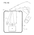
Fig. 4C is a schematic of still another device of the present invention
engaging a tracking surface of human skin;
Fig. 5 is an image of a speckle pattern;
Fig. 6 is an image of a speckle pattern with a larger average speckle
size than the speckle pattern of Fig. 5;
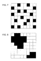
Fig. 7 is a schematic of a detected speckle pattern;
Fig. 8 is a schematic of a detected speckle pattern with a larger average
speckle size than the speckle pattern of Fig. 7;
Fig. 9 is a graph depicting correlation value versus separation
displacement of the device and tracking surface relative each other;
Fig. 10 is a depiction of a one-pixel shift of a copy of a detected
speckle pattern for an auto-correlation calculation;
Fig. 10A is a depiction of the auto-correlation calculation results of the
one-pixel shift of Fig. 10;
Fig. 11 is a depiction of a two-pixel shift of a copy of a detected
speckle pattern for an auto-correlation calculation;
Fig. 11A is a depiction of the auto-correlation calculation results of the
two-pixel shift of Fig. 10;
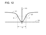
Fig. 12 is a graph demonstrating the relationship between a
summation of differences, auto-correlation value and displacement; and
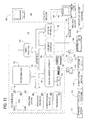
[0028a] Fig. 13 is a block diagram illustrating one example of a suitable
computing system environment in which the invention may be implemented.
DETAILED DESCRIPTION OF THE INVENTION
Referring first to Figs. 1 and 2, a data input device, generally indicated
21, for use with a tracking surface 25 is depicted. Although such a device 21 is typically
capable of tracking relative movement between the device and the tracking surface 25
(described above as horizontal-vertical movement or x-y movement), it should be noted
here that a focus of the present disclosure specifically involves detection of an off-surface
condition. Any of the various tracking schemes known in the relevant art may be coupled
with the teaching of the present invention for lift-off detection. It should be noted here
that the terms "lift-off", "off-surface condition" or "lifting" the device 21 additionally
comprise either lifting, or moving, the tracking surface 25 away from the stationary
device (e.g., Fig. 4C), or lifting the device away from the tracking surface (e.g., Figs. 2
and 4). In addition, referring to relative movement between the device 21 and the
tracking surface 25 in a z-direction may comprise movement of the device (e.g., a mouse
lifted from a mouse pad), movement of the tracking surface (e.g., a moving trackball or
human skin moving in the path of a coherent light beam), or movement of both the
tracking surface and the device.
The device 21 generally comprises a coherent light source 29, such as
a laser, for projecting a coherent light beam B onto the tracking surface 25. The tracking
surface then scatters the coherent light beam striking the tracking surface, thereby
diffusing the light in many directions. As used herein, scattering may also be considered
reflecting the coherent light in many directions. The device 21 further comprises a
detector 35, or detector array, associated with the coherent light source 29 for detecting at
least a portion of the light scattered from the tracking surface 25. Due to the inherent
properties of coherent light, the detected portion of the scattered light comprises a speckle
pattern 33 (Figs. 5 and 6). As described in greater detail below, the detected speckle
pattern 33 may provide an indication of lift-off of the device 21. In one example, the
detector 35 may mount on an integrated circuit. Moreover, both tracking and lift-off
detection may occur simultaneously based upon the same data detected by the detector
35. Suitable detectors may include photodetectors, CCDs (charge-coupled devices),
CMOS (complementary metal-oxide semiconductor) technology, or other detector arrays,
such as those integral with the coherent light source.
The device 21 further comprises a controller 39 responsive to the
detected speckle pattern 33 to operate the device 21 in one of a tracking mode and a non-tracking
mode depending upon a speckle size characteristic of the detected speckle
pattern as determined by the controller 39. The controller processes the output (the
detected speckle pattern 33) of the detector 35 to operate the device 21. Moreover, the
controller 39 is responsive to the speckle pattern 33 to determine a separation distance S
between the device 21 and the tracking surface 25 (see Figs. 2, 4, 4A and 4B), depending
upon the speckle size characteristic of the detected speckle pattern 33 as determined by
the controller 39. In some embodiments, described in more detail below, the speckle size
characteristic is related to the separation distance S between the housing 21 and the
tracking surface 25. Those skilled in the art would recognize that the controller 39 may
be either a processor or an application-specific integrated circuit (ASIC), among other
things. The controller 39 may further comprise imaging processing firmware or circuitry
to process the detected speckle pattern 33, as would be understood by one skilled in the
art.
The device 21 further comprises a housing 45 associated with the
coherent light source 29 and the detector 35 for containing and protecting the components
of the device. The housing 45 includes a support surface 47 adapted to engage the
tracking surface 25 during a tracking mode of the device 21. The housing 45 may take
any form, without departing from the scope of the claimed invention. For example, the
housing 45 may be in the shape of a mouse, a trackball, an optical pen, or any other data
input device 21. The housing 45 further comprises an aperture 49 covered by a
transparent window 51 that allows the coherent light beam B to pass through the housing
and fall upon the tracking surface 25, while limiting the ability of dust and dirt to enter
the housing. The transparent window 51 must be of a sufficient smoothness and
transparency to allow the coherent light beam B to pass freely through the window
without scattering the light back toward the detector, so that the detector improperly
detects a speckle pattern associated with the window, rather than the tracking surface.
Alternately, the window may not be included at all.
Referring now to figs. 3 and 4, a schematic of another device of the
claimed invention, generally indicated 61, comprises a housing 45, a coherent light
source 29, a detector 35, and a controller 39, generally as set forth above. In addition, the
device 61 comprises an optic 63 arranged between the coherent light source 29 and the
tracking surface 25 for refracting the coherent light beam B. Such an optic 63 may be a
converging or a diverging optic, as discussed below with respect to determining an
average speckle grain size. Although not shown, the optic 63 may also be integral with
the coherent light source 29. In other respects, the device 61 of Figs. 3 and 4 functions
similarly to the device 21 of Figs. 1 and 2.
Turning to Fig. 4A, a schematic of yet another device of the claimed
invention, generally indicated 71, comprises several components mounted on a common
substrate 73. Specifically, the device 71 comprises a housing 45, a coherent light source
29, a detector 35, and a controller 39, generally as set forth above. In addition, the
controller 39, the detector 35, and the coherent light source 29 are mounted adjacent each
other on the same substrate 73, providing the added benefit during manufacturing of
allowing these components to be added to the device 71 as a single assembly. Moreover,
the single substrate 73 aids in packaging the device 71 because it is compact and lowers
cost, as only a single substrate is necessary. More importantly, mounting the detector 35
and the coherent light source 29 on the same substrate allows these two components to be
mounted closer to one another for compactness. The substrate 73 may comprise at least
one of a micro-chip, a printed circuit board (PCB), and a leadframe. In other respects, the
device 67 of Fig. 4A functions similarly to the device 21 of Figs. 1 and 2.
In general, numerous types of tracking surfaces 25 will scatter the
coherent light beam B to provide a sufficient amount of scattered light back toward the
detector 35 for detection as a speckle pattern 33. In particular, tracking surfaces 25 that
are optically rough have adequate light-scattering properties with respect to the device
21. An optically rough surface scatters coherent, or laser, light in many directions,
making the orientation of the coherent light beam B with respect to the tracking surface
25 relatively unimportant (with respect to detecting the scattered light comprising the
speckle pattern 33). For example, for optically rough tracking surfaces 25, the coherent
light beam B may be oriented at several acceptable angles relative to the tracking surface
because the optically rough tracking surface scatters the light in many directions,
including toward the detector 35. For instance, optically rough surfaces include many
common tracking surfaces 25, including paper, wood, metal, fabric, certain plastics, and
human skin (e.g., Fig. 4C).
Only surfaces that are perfectly reflective, i.e., mirror-like, such as a
ground and polished, optic-quality, flat, transparent glass, are insufficiently rough enough
to scatter the coherent light beam B in many directions. These surfaces will act as a
mirror and primarily reflect laser light exactly opposite the angle of incidence of the laser
29, rather than scattering the light in many directions. For the present device 21 to detect
lift-off from such a tracking surface 25, the laser 29 and detector 35 may be oriented as
shown in the schematic in Fig. 4B. The device depicted in Fig. 4B, generally indicated
81, comprises a housing 45, a coherent light source 29, a detector 35, and a controller 39,
generally as set forth above. In addition, the device 81 includes a beam splitter 83 for
reflecting the coherent light beam B. Such a beam splitter 83 allows at least some light
striking a first side of the beam splitter to pass through the beam splitter in one direction,
while reflecting at least some light striking a second side of the beam splitter. More
importantly, the beam splitter 83 does not significantly scatter, or diffuse, the light and
therefore does not generate speckle. Even if the detector 35 detects the light beam B
passing through the beam splitter 83, the detected light does not contain the essential
properties necessary for determining an off-surface condition. For the present device 81,
the beam splitter 83 is oriented at an oblique angle relative to the coherent light beam B
reflected from the tracking surface 25 (e.g., 785 milliradians (45 degrees)), and the
detector 35 mounts in the path of the coherent light reflected by the beam splitter. In this
configuration, the coherent light beam B may be oriented perpendicular to the tracking
surface 25 during the tracking mode, thereby allowing lift-off detection from a highly
reflective tracking surface that does not scatter a speckle pattern in many directions.
Referring now to Fig. 4C, a device, generally indicated 101, is
depicted wherein the tracking surface 25 is human skin. In particular, the tracking
surface 25 shown is a human finger. This device 101 demonstrates that the device itself
may be stationary while the tracking surface 25 moves relative to the device. The
functioning of the device components, such as the coherent light source 29, the detector
35, and the controller 39, is similar to those noted above. The device 101 depicted in Fig.
4C allows the user to move his hand, the tracking surface 25, over the device such that
when the finger moves away from the device, the detector 35 and controller 39 are able to
detect an off-surface condition and stop tracking, respectively.
As noted above, exemplary speckle patterns 33 are depicted in both
Figs. 5 and 6. In general, speckle patterns 33 captured by the detector 35 array have
particular statistical properties based upon the inherent properties of laser speckle and the
geometry of the device 21, 61, 71, 81, 101. Such properties may be useful in detecting
lift-off from a tracking surface 25. The speckle pattern 33' of Fig. 5 generally includes
smaller speckle grains, on average, than the speckle grains of speckle pattern 33" of Fig.
6. The difference in average speckle grain size between Figs. 5 and 6 is one example of
the type of speckle grain size change that may be indicative of lift-off of the device 21,
61, 71, 81, 101. As the device moves relative to the tracking surface 25, speckle grain
size changes, thereby altering the contrast of the detected speckle pattern 33. By
analyzing changes in speckle grain size and/or speckle pattern 33 contrast, the separation
distance S between the device 21,61,71,81, 101 and the tracking surface 25 may be
determined.
Turning to one relationship governing speckle behavior, the average
speckle grain size of a coherent light beam B scattered off of an optically rough surface is
given generally by
σ = 1.22λL D
where σ is the average width of a speckle grain at the detector 35, λ is the wavelength of
the coherent light beam B, L is the distance from the detector to the tracking surface 25,
and D is the width of the beam, or illumination diameter, at the tracking surface (see Figs.
1-4C). The wavelength λ of the coherent light beam B and the distance L from the
detector 35 to the tracking surface 25 are directly proportional to average speckle grain
size σ. The illumination diameter D is inversely proportional to average speckle grain
size σ.
Therefore, according to the equation noted immediately above, as the
device 21, 61, 71, 81, 101 and the tracking surface 25 move apart from one another (e. g. ,
compare Figs. 1 and 2), the distance L increases, and the illumination diameter D may
increase, decrease, or stay the same, depending upon the shape of the coherent light beam
B. In one example, the coherent light beam B may converge due to a converging optic 63
in the path of the coherent light beam (see Figs. 3 and 4). Because the beam B
converges, D will decrease as L increases, thereby increasing the average width of the
speckle grains σ according to the above equation. In another example, the beam B may
diverge (see Figs. 1, 2, 4A, and 4B) due to an inherent characteristic of the coherent light
source 29 or due to a diverging optic (not shown). In this case, D will increase as L
increases, such that the average width of each speckle grain σ may increase or decrease
according to the above equation, depending upon the rate of change of both D and L as
the device 21, 71, 81 and the tracking surface 25 move apart from one another. To ensure
that the average speckle grain size σ increases as the device 21, 71, 81 and the tracking
surface 25 move apart from one another, L should increase at a faster rate than D. Both
the distance T between the detector 35 and the support surface 47 of the device 21, 71, 81
(e.g., Figs. 2 and 4) and an angle of inclusion β of the coherent light beam B (e.g., Figs. 1
and 2) are factors affecting the rate of increase of the illumination diameter D with
respect to the distance L from the detector to the tracking surface 25. For instance,
decreasing the distance T between the detector 35 and the support surface 47 of the
device 21, 71, 81 and decreasing the angle of inclusion β of the coherent light beam B
will both, to varying degrees, increase the rate at which the average speckle grain size σ
will increase as the device and the tracking surface 25 move apart from one another. In
yet another example, the coherent light beam B neither converges nor diverges, but rather
may comprise a beam of uniform width D at all distances from the coherent light source.
By maintaining a constant width D, only L, the distance from the detector 35 to the
tracking surface 25, changes as the separation distance S increases or decreases.
Therefore, increasing the separation distance S increases the distance L, which increases
speckle grain size σ in all cases. One skilled in the art would readily understand how to
arrange the components of the device 21, 61, 71, 81, 101 such that average speckle grain
size σ will increase as the device and the tracking surface 25 move apart from one
another.
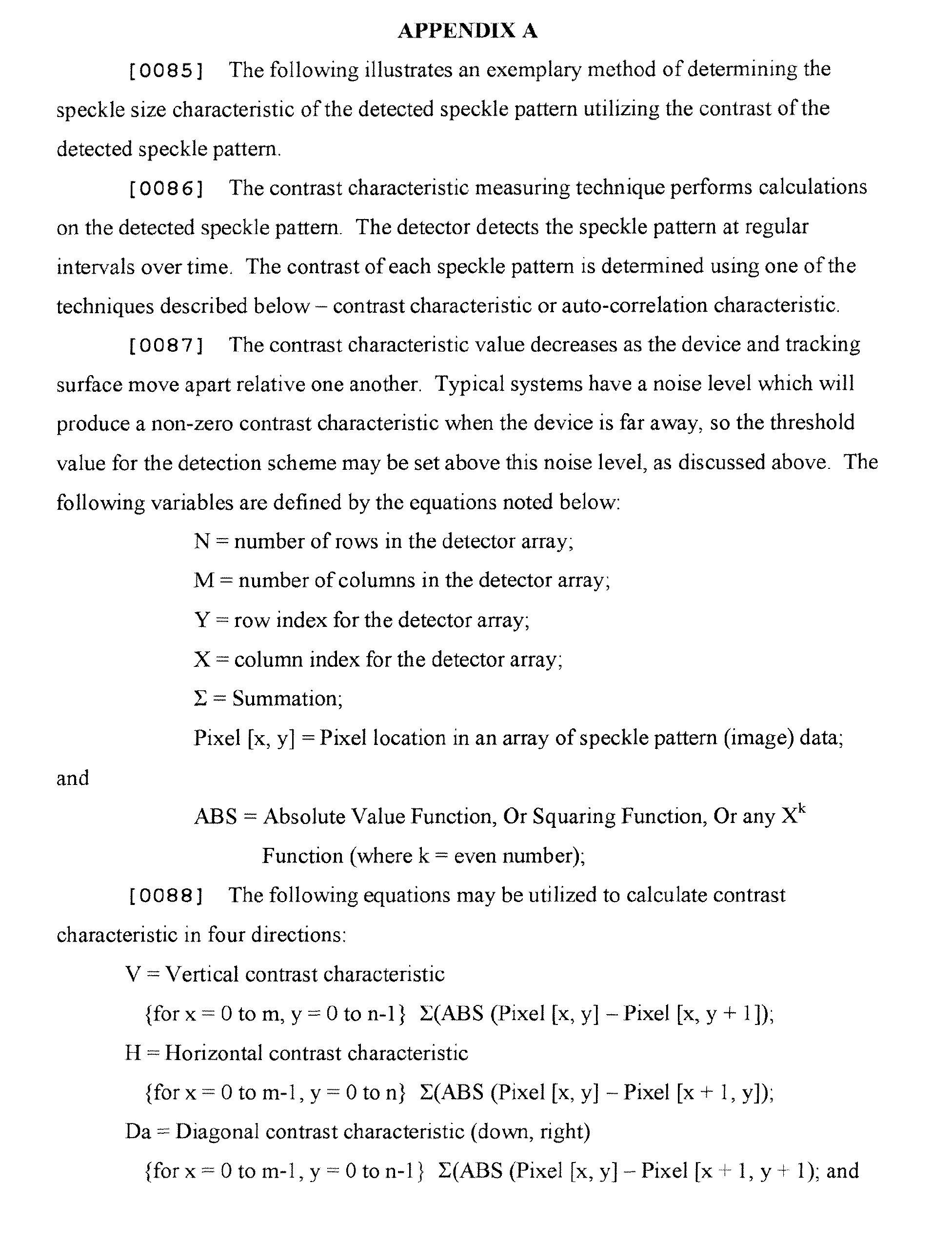
In one embodiment, the speckle size characteristic is a contrast
characteristic of the detected
speckle pattern 33. An exemplary technique for
determining the contrast characteristic of the detected
speckle pattern 33 is set forth in
detail below in Appendix A, although other techniques are contemplated as within the
scope of the claimed invention. In one example, the
controller 39 may determine the
contrast characteristic in one direction of the detected
speckle pattern 33. For instance,
Figs. 7 and 8 are schematics of detected
speckle patterns 33. The
speckle pattern 33" of
Fig. 8 includes a larger average speckle grain size σ than the speckle pattern 33' of Fig. 7.
The
speckle patterns 33', 33" and the vertical contrast equation (V) of Appendix A yield
vertical contrast characteristics of 27 and 11 for
patterns 33' and 33", respectively.
Because the speckle pattern 33' has a larger vertical contrast characteristic than the
speckle pattern 33", one may infer that the average speckle grain size σ of Fig. 7 is
smaller than that of Fig. 8. Similarly, the
speckle patterns 33', 33" and the horizontal
contrast equation (H) of Appendix A yield horizontal contrast characteristics of 26 and 10
for
patterns 33' and 33", respectively. Again, because the speckle pattern 33' comprises a
larger horizontal contrast characteristic than the
speckle pattern 33", one may infer that
the average speckle grain size σ of Fig. 7 is smaller than that of Fig. 8. The contrast
characteristics of
speckle patterns 33' and 33" for each of the contrast equations are
depicted in the following table:
| | V | H | Da | Db |
| 33' | 27 | 26 | 22 | 20 |
| 33" | 11 | 10 | 12 | 11 |
In each direction, the contrast characteristic of speckle pattern 33'
exceeds the contrast characteristic of speckle pattern 33".
In another example, the
controller 39 may determine the contrast
characteristic in at least two directions. The
controller 39 in still another example may
determine the contrast characteristic in at least four directions. In addition to these
exemplary calculations, the contrast characteristic measurements may be combined
according to the contrast equations of Appendix A to yield the following contrast
characteristic values for the detected
speckle patterns 33' and 33":
| | Contrast1 | Contrast2 | Contrast3 | Contrast4 | Contrast99 |
| 33' | 27 | 53 | 95 | 26.5 | 23.75 |
| 33" | 11 | 21 | 44 | 10.5 | 11 |
For each contrast characteristic calculation, the contrast characteristic of speckle pattern
33' exceeds that of
speckle pattern 33". The contrast characteristic may also be an
average of the contrast in N directions (e.g., 2, 4, 6, ... N directions).
Once the contrast characteristic of a detected speckle pattern 33 is
determined, there are several possible ways of determining if the device 21, 61, 71, 81,
101 is operating in the tracking mode or the non-tracking mode. In one example, the
controller 39 compares the contrast characteristic of the detected speckle pattern 33 with
a threshold contrast characteristic for operating the device 21, 61, 71, 81, 101 in the
tracking mode or the non-tracking mode. In this example, once the detected contrast
characteristic falls below the threshold contrast characteristic, the controller 39
determines that the device 21, 61, 71, 81, 101 should be operating in a non-tracking mode
and suspends tracking of the device relative to the tracking surface 25. Such a threshold
contrast characteristic may be a baseline noise contrast characteristic as measured by the
detector 35 when the device 21, 61, 71, 81, 101 is remote from the tracking surface 25, or
when the coherent light source 29 is not projecting the coherent light beam, such as when
the coherent light source is turned off. Such a baseline noise characteristic may be set in
the controller 39 hardware or software.
In another example, the manufacture of each device 21, 61, 71, 81, 101
comprises individually calibrating each device to a specific contrast threshold. A nonvolatile
memory location in the device 21, 61, 71, 81, 101 may store the threshold.
In still another example, the controller 39 compares the contrast
characteristic of the detected speckle pattern 33 to a previous contrast characteristic of a
previously detected speckle pattern for operating the device in the tracking mode or the
non-tracking mode. Instead of comparing the contrast characteristic to a constant
threshold, the controller 39 compares the presently determined contrast characteristic to a
previously determined contrast characteristic. The controller 39 may therefore
continuously monitor the contrast characteristic to determine if it changes significantly
over time, thereby indicating relative separation between the device 21 and the tracking
surface 25.
In yet another example, the device 21, 61, 71, 81, 101 may compare
the current contrast characteristic to both the threshold contrast characteristic and the
previously determined contrast characteristic.
Referring now to Fig. 9, a graph includes a curve 111 depicting
separation displacement S of the device 21, 61, 71, 81, 101 and the tracking surface 25
relative each other along an x-axis versus contrast 115 of the detected speckle pattern 33
along a y-axis. The graph depicts the relationship between the detected contrast of the
speckle pattern 33 and separation displacement S. Where separation displacement S of
the device 21, 61, 71, 81, 101 is near zero (x is close to 0) (see Figs. 1, 3, and 4C), the
curve 111 peaks, indicating a speckle pattern 33 of relatively small average speckle size
and nearly no separation distance S, or lift-off, between the device 21, 61, 71, 81, 101 and
the tracking surface 25. In other words, a separation displacement S of near zero
corresponds to a nominal operating distance of the device 21, 61, 71, 81, 101 engaging
the tracking surface 25. As displacement S increases (x > 0), the contrast 115 falls from
its peak along curve 111, thereby indicating a speckle pattern 33 of lower contrast, or
relatively larger average speckle size. Once displacement S increases by a relatively
large amount (x >> 0), the contrast 115 falls even lower, indicating a speckle pattern 33
with relative large average speckle size.
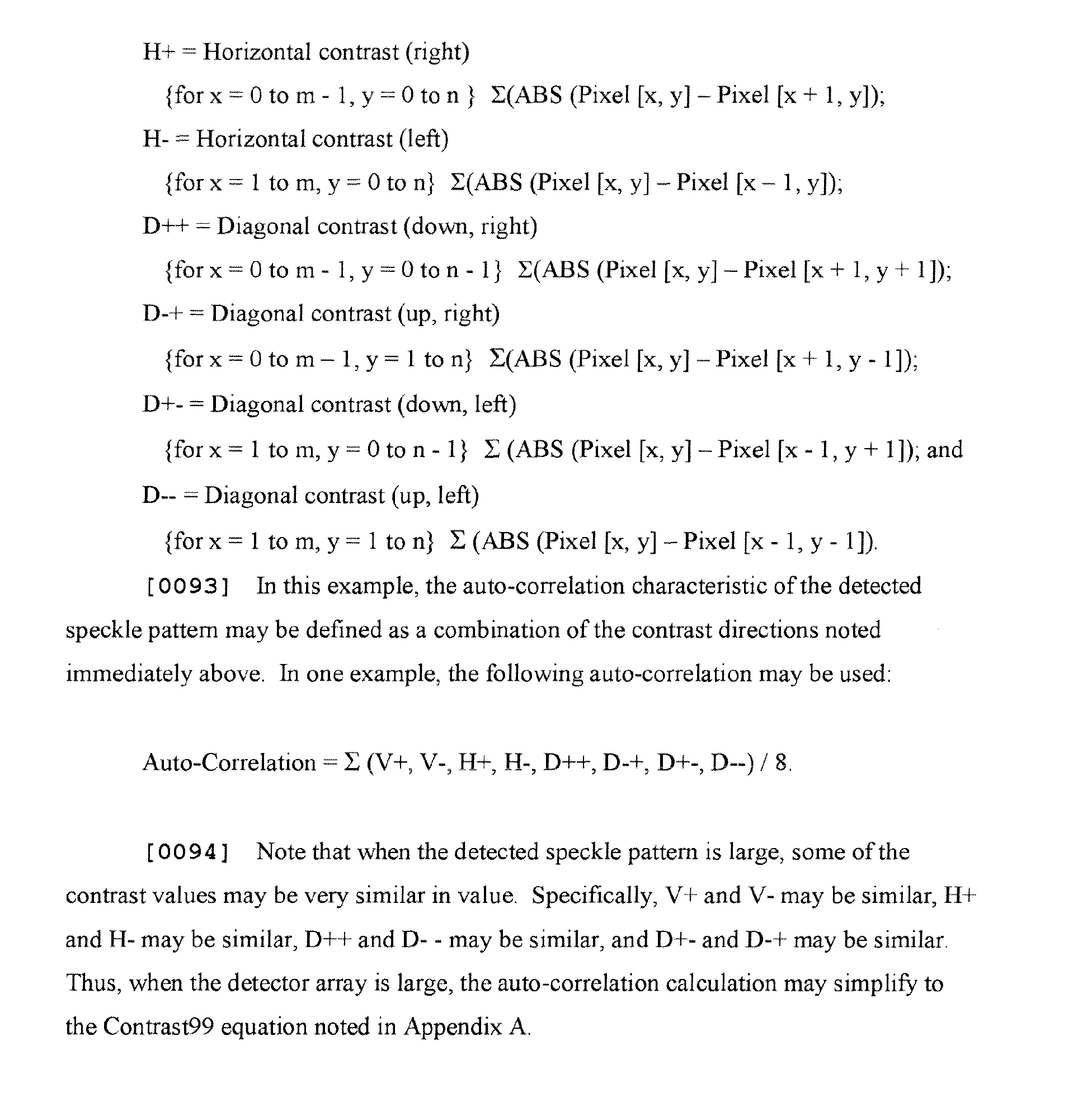
In a further example, the controller 39 of the device 21, 61, 71, 81, 101
determines the speckle size characteristic by determining an auto-correlation
characteristic of the detected speckle pattern 33. An auto-correlation characteristic is a
mathematical comparison of an image to itself Comparing adjacent pixels within the
image with one another provides a measurement of the image's contrast. Two examples
of auto-correlation are discussed in detail herein. A first example determines an auto-correlation
value representative of image contrast by comparing each pixel of the
detected speckle pattern to its nearest neighbor by shifting the speckle pattern a single
pixel in one or more directions and determining the difference between each stationary
pixel and each corresponding shifted pixel. A second example determines an auto-correlation
value indicative of speckle size by shifting the detected speckle pattern one or
more pixels in one or more directions to determine when the contrast between the
stationary and shifted speckle patterns pass a particular threshold, which is in turn
indicative of the speckle size.
Turning to the first auto-correlation example, a general auto-correlation
equation is set forth in detail below in Appendix B. In this example, the
controller 39 may determine the speckle auto-correlation characteristic by comparing
each pixel of a detected speckle pattern 33 to each of the pixel's nearest neighbors. In
other words, the speckle pattern 33 may be collectively shifted one pixel in a particular
direction for determining the difference between each stationary pixel and each
corresponding shifted pixel. The speckle pattern may then be collectively shifted one
pixel in another direction for a similar determination, and so forth. These value may then
be collected and operated upon as described an Appendix B to yield an overall auto-correlation
value for the detected speckle pattern 33. The shifting and comparison may
occur in eight directions, including vertical up, vertical down, horizontal left, horizontal
right, diagonal down and right, diagonal up and right, diagonal down and left, and
diagonal up and left, as is discussed in greater detail in Appendix B.
As with the contrast characteristic, once the auto-correlation
characteristic of the detected speckle pattern 33 is determined, there are several possible
ways of determining if the device 21, 61, 71, 81, 101 is operating in the tracking mode or
the non-tracking mode. In one example, the controller 39 compares the auto-correlation
characteristic with a threshold auto-correlation characteristic for operating the device 21,
61, 71, 81, 101 in the tracking mode or the non-tracking mode. In this example, once the
auto-correlation characteristic falls below the threshold auto-correlation characteristic,
the controller 39 determines that the device 21, 61, 71, 81, 101 should be operating in a
non-tracking mode and suspends tracking of the tracking surface 25. In another example,
the controller 39 compares the auto-correlation characteristic of the detected speckle
pattern 33 to a previous auto-correlation characteristic of a previously detected speckle
pattern for operating the device 21, 61, 71, 81, 101 in the tracking mode or the non-tracking
mode. In another example, the device may compare the current auto-correlation
characteristic to both the threshold auto-correlation characteristic and the previously
determined auto-correlation characteristic.
Turning to the second example, auto-correlation may also be utilized
to determine the contrast of the detected speckle pattern 33 by displacing a copy of the
speckle pattern, with respect to itself, one pixel width at a time and comparing the two
speckle patterns until a particular auto-correlation threshold of the combined images is
reached. Referring now to Fig. 10, a second copy 33B of the detected speckle pattern of
Fig. 8 is shown overlapping a first copy 33A of the detected speckle pattern. The second
copy 33B is shifted one pixel to the right and one pixel upward, relative to the first copy
33A. For identification purposes, the speckle features of the first copy 33A and the
second copy 33B of the speckle pattern are identically positioned in each respective
array, yet each is identified by a contrasting first hatch pattern H1 and second hatch
pattern H2, respectively. Moreover, any pixel locations wherein the hatch pattern of both
the first and second copies overlap are depicted as a third, combination, hatch pattern H3.
These hatch patterns H1, H2, H3 provide a pictorial view of the interaction of the
overlapping speckle patterns 33A, 33B as the pattern is compared with itself For
example, in Fig. 10, speckle features on the first copy 33 A of the speckle pattern include
a hatch pattern H1 with lines extending upward to the right, while speckle features on the
second copy 33B of the speckle pattern include a hatch pattern H2 with lines extending
upward to the left. Therefore, once the second copy 33B is shifted, overlapping speckle
features will cooperate with one another to show a third speckle pattern H3 with crossed
lines.
Applying an auto-correlation to the combined speckle patterns 33A,
33B requires selecting an operator for operating on the overlapping speckle features of
the first and second copies of the speckle pattern. Any operator may be used, for
example, multiplication, summation or subtraction, to name a few. In this example,
subtraction is the operator, whereby, the image intensity value of each pixel is subtracted
from each overlapping pixel and an absolute value of the result is taken, according to the
equation included in Appendix B. In this simplified example, the speckle image is
binary, such that the result of the subtraction is a value for each pixel of zero or one, as
shown in each pixel Fig. 10A. Once each individual pixel value is determined, the entire
array may be summed to establish the auto-correlation value for the specified shift. Thus,
the auto-correlation value for this portion of the example is 16.
Turning now to Figures 11 and 11A, the second copy 33B of the
detected speckle pattern is shifted two pixels to the right and two pixels upward relative
to the first copy 33A. As above, an auto-correlation calculation is applied to the
combined images, thereby calculating the values for each pixel, as depicted in Fig. 11A.
The auto-correlation value for this portion of the example is 25. Although only two
portions of the auto-correlation calculation are depicted here, one skilled in the art would
appreciate that the second copy 33B of the detected speckle pattern may be shifted
additional pixels up and to the right for an additional five calculations in this particular
direction. In addition, the second copy 33B may be shifted in other directions for
calculating the auto-correlation in the vertical, horizontal and other diagonal directions,
as explained in detail in Appendix B. Moreover, with a detector array having more
pixels, additional auto-correlation calculations may be performed.
Combining these summation of differences values together and
plotting them with respect to the shift of the second copy 33B of the speckle pattern
yields a graph resembling the one depicted in Fig. 12. Specifically, the graph includes a
curve 121 demonstrating the relationship between a summation of differences, auto-correlation
value 123 of a detected speckle pattern (y-axis) and displacement of the
detected speckle pattern 125 with respect to itself (x-axis). Where displacement of the
second copy 33B with respect to the first copy 33A is zero (x = 0), the auto-correlation
curve 121 defines a minimum of zero, indicating no difference between the speckle
pattern and itself, or a substantially perfect correlation. This result is self-evident,
considering that the difference between something and itself is zero. As the second copy
33B shifts with respect to the first copy 33A in one direction or another, pixel by pixel,
the summation of differences auto-correlation value increases from its minimum,
indicating a larger difference between the speckle pattern and itself, or a lower correlation
between the overlapped speckle pattems. This is borne out by the examples noted above,
where the summation of differences auto-correlation value increases to 16 with a one-pixel
shift and increases to 25 with a two-pixel shift. Once displacement of the second
copy 33B of the speckle image increases by a relatively large amount (x << 0 or x >> 0),
the summation of differences auto-correlation value increases even higher, indicating
large differences between the speckle patterns, or very little correlation between the
speckle patterns.
Although the general shape of the curve 121 is similar for most
detected speckle patterns, its shape changes according to the average speckle grain size σ
of the speckle pattern 33. Where average speckle grain size σ is relatively large, such as
those shown in Figs. 10, 10A, 11 and 11 A, each pixel step away from the minimum has a
relatively small impact on the summation of differences waveform correlation value
relative to the displacement of the speckle pattern. This is because larger speckles,
although misaligned, will have more overlap with one another than smaller speckle grains
translated a similar distance. For the larger speckles, the shift will identify several
differences over the combined array, while many of the pixels will overlap a pixel having
a similar value, yielding no difference. Conversely, where average speckle grain size σ is
relatively small (Fig. 5), each pixel step away from the minimum will create a larger
increase in the summation of differences waveform correlation value because smaller
speckles will tend to misalign to a large degree relative one another. Thus, smaller
speckle grains will yield a curve 121 having a narrower trough that increases in value
more quickly as a function of displacement 125 than a similarly displaced speckle pattern
comprised of larger speckle grains. Importantly, a line of constant auto-correlation value,
or threshold 127, passing through the curve 121 will intersect the curve at two points E
and F. The distance between such points is related to the average speckle grain size σ
and may be utilized as the speckle size characteristic.
It should be understood by those skilled in the art that other operators
will yield a differently shaped auto-correlation curve. For instance, introducing addition
as the operator will invert curve 121, yielding a maximum, rather than a minimum at zero
displacement 125. In addition, the graph depicted in Fig. 12 depicts auto-correlation
readings in only two opposed directions, such as left and right or up and down. One
skilled in the art would understand that such auto-correlation values may be calculated by
shifting the speckle pattern in any direction. Moreover, such calculations may be
combined to produce several curves that together may more accurately define the size
and shape of the detected speckles. Furthermore, one skilled in the art would appreciate
that the auto-correlation need not be calculated pixel-by-pixel beginning with
displacement of one pixel and ending at the end of the detected array. For example, if
any auto-correlation value for a particular pixel shift exceeds a given threshold, the
analysis may end because the speckle size is effectively determined. Moreover, one may
determine where to begin the analysis based upon the auto-correlation values of the
previous calculation or by where it appears the auto-correlation values are moving.
In another example, the controller 39 determines the contrast
characteristic of the detected speckle pattern 33 by determining a number of image
intensity transitions across the speckle pattern 33. Image intensity transitions constitute
determining the number of high to low transitions, or speckle grain edges, that exist in the
speckle pattern 33. This determination differs from the contrast characteristic and auto-correlation
characteristic methodologies described above. While the contrast
characteristic determines the intensity changes between each adjacent pixel of the speckle
pattern 33, determining the number of image intensity transitions focuses on only those
differences in adjacent pixels corresponding to a high to low transition or to a low to high
transition. Such transitions mark the edge of a speckle grain. In other words, only those
differences in adjacent pixels that exceed a particular minimum value will become a part
of the evaluation.
In another embodiment, the device 21, 61, 71, 81, 101 performs a
spatial frequency analysis of the detected speckle pattern 33 to determine the speckle size
characteristic. One such spatial frequency analysis performed by the controller is a Fast
Fourier Transform (FFT) analysis. An FFT analysis focuses on the spatial transition of
the detected speckle pattern 33, specifically the different spatial modulations of the
detected signal. In particular, a signal having a larger proportion of its spatial frequency
content at a high spatial frequency is consistent with small average speckle grain size σ,
while a signal having a larger proportion of its spatial frequency content at a low spatial
frequency is consistent with large average speckle grain size. To utilize this spatial
information from the detected speckle pattern 33, the spatial frequency content is broken
into particular spatial frequency ranges, thereby creating a histogram indicative of the
spatial frequency content.
In one example, three spatial frequency ranges are utilized, namely a
low spatial frequency range, a medium spatial frequency range and a high spatial
frequency range. Where much of the spatial frequency content falls within the high
spatial frequency range, the speckle pattern 33 is determined to include relatively small
speckle grains on average, indicating the device 21, 61, 71, 81, 101 is substantially
engaged with the tracking surface 25. In contrast, where much of the spatial frequency
content falls within the low spatial frequency range, the speckle pattern 33 is determined
to include relatively large speckle grains, indicating the device 21, 61, 71, 81, 101 is not
substantially engaged with the tracking surface 25. The FFT analysis provides data for
this type of analysis, as one skilled in the art would readily appreciate. In this manner,
the controller 39 may readily monitor the content of the spatial frequency range to
determine if lift-off has occurred. In another example, a band pass filter may be included
to focus the inquiry on a particular spatial frequency band that includes an appropriate
sensitivity to changes in lift-off. Other types of spatial frequency analysis (e.g., cosine
transform, other Fourier transforms, etc.) may be utilized in a similar fashion without
departing from the scope of the claimed invention.
In addition to the embodiments described above for determining
average speckle grain size σ, another embodiment of the claimed invention comprises
measuring the width of at least one speckle grain of the speckle pattern 33 and
monitoring the changes to the speckle grain width to determine the operating mode of the
device, generally as set forth above.
It should be noted that any of the above-described techniques for
determining the speckle size characteristic may be utilized redundantly with one another
(e.g., a contrast characteristic determination combined with a spatial frequency analysis)
to ensure the off-surface condition is detected, either by reducing false positives or
increasing lift-off sensitivity.
Any of the devices 21, 61, 71, 81, 101 of the claimed invention
described above may incorporate one of a variety of different coherent light sources 29
(e.g., lasers) having different properties. In one instance, the device 21, 61, 71, 81, 101
may include a coherent light source 29 capable of producing a coherent light beam B
having an angle of inclusion β of less than about 790 milliradians (45 degrees). Another
device 21, 61, 71, 81, 101 may cantral the angle of inclusion β of its coherent light beam
B to less than about 170 milliradians (10 degrees). Still another device 21, 61, 71, 81,
101 may control the angle of inclusion β of its coherent light beam B to less than about
87 milliradians (5 degrees). Such coherent light sources 29 may control beam divergence
in any number of ways without departing from the scope of the claimed invention. As
discussed above with respect to Figs. 3 and 4, the device 21 may comprise an optic 63
refracting the coherent light beam B between the coherent light source 29 and the
tracking surface 25. Although not shown, the optic may also be integral with the
coherent light source 29.
Exemplary lasers 29 will draw as little current as possible. For
instance, a suitable laser 29 consumes less than about 20 milli-Amps of current during
operation. This ensures that the laser 29 may be used in a cordless device application
without unduly limiting the battery life of the device. In particular, the laser 29 may also
be a solid-state device, such as a vertical cavity surface emitting laser (VCSEL) or an
edge-emitting laser (EEL). Other lasers and sources of laser, or coherent, light may also
be utilized without departing from the scope of the claimed invention.
The present invention further includes a method comprising projecting
a coherent light beam B from a data input device 21, 61, 71, 81, 101 onto a tracking
surface 25 having light-scattering properties, generally as set forth above. The method
further comprises detecting at least a portion of the light scattered by the tracking surface
25. The detected scattered light comprises a speckle pattern 33. The method further
comprises determining if the device 21, 61, 71, 81, 101 is spatially separated from the
tracking surface 25 by at least a lift-off detection distance as a function of a speckle size
characteristic of the detected speckle pattern 33. The method further comprises either (i)
suspending tracking of relative movement between the device 21, 61, 71, 81, 101 and the
tracking surface 25 when the device is spatially separated from the tracking surface by at
least the lift-off detection distance or (ii) maintaining tracking of relative movement
between the device and the tracking surface when the device is spatially separated from
the tracking surface by less than the lift-off detection distance. The lift-off detection
distance is a design parameter incorporated into the device 21, 61, 71, 81, 101 as a
transition between surface tracking and lift-off, whereby the user may expect the device
to temporarily suspend tracking for device repositioning.
In another embodiment, the method may further comprise determining
a contrast characteristic of the detected speckle pattern 33, generally as set forth above.
The method may further comprise comparing the contrast characteristic of the detected
speckle pattern 33 with a threshold contrast characteristic. The method may further
comprise comparing the contrast characteristic of the detected speckle pattern 33 to a
previous contrast characteristic of a previously detected speckle pattern.
In still another embodiment, the determining comprises determining a
number of image intensity transitions across the detected speckle pattern 33, generally as
set forth above. In yet another embodiment, the determining comprises performing a
spatial frequency analysis of the detected speckle pattern to determine the speckle size
characteristic. The performing of a spatial frequency analysis may comprise performing
a Fast Fourier Transform (FFT) analysis, generally as set forth above, or other spatial
frequency analyses.
In another embodiment, the determining comprises measuring a width
of at least one speckle grain of the detected speckle pattern 33 and monitoring changes to
the width of the at least one speckle grain, generally as set forth above. In still another
embodiment, the determining comprises determining an auto-correlation characteristic of
the detected speckle pattern, generally as set forth above.
In yet another embodiment, the lift-off detection distance is no more
than about 10 millimeters (0.39 inch). In still another embodiment, the lift-off detection
distance is no more than about 4 millimeters (0.16 inch). In a further embodiment, the
lift-off detection distance is no more than about 4 millimeters (0.16 inch) and at least
about 1 millimeter (0.04 inch).
Fig. 13 shows one example of a general purpose computing device in
the form of a computer 130. In one embodiment of the invention, a computer such as the
computer 130 is suitable for use in the other figures illustrated and described herein.
Computer 130 has one or more processors or processing units 132 and a system memory
134. In the illustrated embodiment, a system bus 136 couples various system
components including the system memory 134 to the processors 132. The bus 136
represents one or more of any of several types of bus structures, including a memory bus
or memory controller, a peripheral bus, an accelerated graphics port, and a processor or
local bus using any of a variety of bus architectures. By way of example, and not
limitation, such architectures include Industry Standard Architecture (ISA) bus, Micro
Channel Architecture (MCA) bus, Enhanced ISA (EISA) bus, Video Electronics
Standards Association (VESA) local bus, and Peripheral Component Interconnect (PCI)
bus also known as Mezzanine bus.
The computer 130 typically has at least some form of computer
readable media. Computer readable media, which include both volatile and nonvolatile
media, removable and non-removable media, may be any available medium that can be
accessed by computer 130. By way of example and not limitation, computer readable
media comprise computer storage media and communication media. Computer storage
media include volatile and nonvolatile, removable and non-removable media
implemented in any method or technology for storage of information such as computer
readable instructions, data structures, program modules or other data. For example,
computer storage media include RAM, ROM, EEPROM, flash memory or other memory
technology, CD-ROM, digital versatile disks (DVD) or other optical disk storage,
magnetic cassettes, magnetic tape, magnetic disk storage or other magnetic storage
devices, or any other medium that can be used to store the desired information and that
can be accessed by computer 130. Communication media typically embody computer
readable instructions, data structures, program modules, or other data in a modulated data
signal such as a carrier wave or other transport mechanism and include any information
delivery media. Those skilled in the art are familiar with the modulated data signal,
which has one or more of its characteristics set or changed in such a manner as to encode
information in the signal. Wired media, such as a wired network or direct-wired
connection, and wireless media, such as acoustic, RF, infrared, and other wireless media,
are examples of communication media. Combinations of the any of the above are also
included within the scope of computer readable media.
The system memory 134 includes computer storage media in the form
of removable and/or non-removable, volatile and/or nonvolatile memory. In the
illustrated embodiment, system memory 134 includes read only memory (ROM) 138 and
random access memory (RAM) 140. A basic input/output system 142 (BIOS), containing
the basic routines that help to transfer information between elements within computer
130, such as during start-up, is typically stored in ROM 138. RAM 140 typically
contains data and/or program modules that are immediately accessible to and/or presently
being operated on by processing unit 132. By way of example, and not limitation, Fig. 13
illustrates operating system 144, application programs 146, other program modules 148,
and program data 150.
The computer 130 may also include other removable/non-removable,
volatile/nonvolatile computer storage media. For example, Fig. 13 illustrates a hard disk
drive 154 that reads from or writes to non-removable, nonvolatile magnetic media. Fig.
13 also shows a magnetic disk drive 156 that reads from or writes to a removable,
nonvolatile magnetic disk 158, and an optical disk drive 160 that reads from or writes to a
removable, nonvolatile optical disk 162 such as a CD-ROM or other optical media.
Other removable/non-removable, volatile/nonvolatile computer storage media that can be
used in the exemplary operating environment include, but are not limited to, magnetic
tape cassettes, flash memory cards, digital versatile disks, digital video tape, solid-state
RAM, solid-state ROM, and the like. The hard disk drive 154, and magnetic disk drive
156 and optical disk drive 160 are typically connected to the system bus 136 by a nonvolatile
memory interface, such as interface 166.
The drives or other mass storage devices and their associated computer
storage media discussed above and illustrated in Fig. 13, provide storage of computer
readable instructions, data structures, program modules and other data for the computer
130. In Fig. 13, for example, hard disk drive 154 is illustrated as storing operating
system 170, application programs 172, other program modules 174, and program data
176. Note that these components can either be the same as or different from operating
system 144, application programs 146, other program modules 148, and program data
150. Operating system 170, application programs 172, other program modules 174, and
program data 176 are given different numbers here to illustrate that, at a minimum, they
are different copies.
A user may enter commands and information into computer 130
through input devices or user interface selection devices such as a keyboard 180 and a
pointing device 182 (e.g., a mouse, trackball, pen, or touch pad). Other input devices (not
shown) may include a microphone, joystick, game pad, satellite dish, scanner, finger
tracker, or the like. These and other input devices are connected to processing unit 132
through a user input interface 184 that is coupled to system bus 136, but may be
connected by other interface and bus structures, such as a parallel port, game port, PS/2
port or a Universal Serial Bus (USB). A monitor 188 or other type of display device is
also connected to system bus 136 via an interface, such as a video interface 190. In
addition to the monitor 188, computers often include other peripheral output devices (not
shown) such as a printer and speakers, which may be connected through an output
peripheral interface (not shown).
The computer 130 may operate in a networked environment using
logical connections to one or more remote computers, such as a remote computer 194.
The remote computer 194 may be a personal computer, a server, a router, a network PC, a
peer device or other common network node, and typically includes many or substantially
all of the elements described above relative to computer 130. The logical connections
depicted in Fig. 13 include a local area network (LAN) 196 and a wide area network
(WAN) 198, but may also include other networks. LAN 136 and/or WAN 138 can be a
wired network, a wireless network, a combination thereof, and so on. Such networking
environments are commonplace in offices, enterprise-wide computer networks, intranets,
and global computer networks (e.g., the Internet).
When used in a local area networking environment, computer 130 is
connected to the LAN 196 through a network interface or adapter 186. When used in a
wide area networking environment, computer 130 typically includes a modem 178 or
other means for establishing communications over the WAN 198, such as the Internet.
The modem 178, which may be internal or external, is connected to system bus 136 via
the user input interface 184, or other appropriate mechanism. In a networked
environment, program modules depicted relative to computer 130, or portions thereof,
may be stored in a remote memory storage device (not shown). By way of example, and
not limitation, Fig. 13 illustrates remote application programs 192 as residing on the
memory device. It will be appreciated that the network connections shown are exemplary
and other means of establishing a communications link between the computers may be
used.
Generally, the data processors of computer 130 are programmed by
means of instructions stored at different times in the various computer-readable storage
media of the computer. Programs and operating systems are typically distributed, for
example, on floppy disks or CD-ROMs. From there, they are installed or loaded into the
secondary memory of a computer. At execution, they are loaded at least partially into the
computer's primary electronic memory. The invention described herein includes these
and other various types of computer-readable storage media when such media contain
instructions or programs for implementing the operations described below in conjunction
with a microprocessor or other data processor.
For purposes of illustration, programs and other executable program
components, such as the operating system, are illustrated herein as discrete blocks. It is
recognized, however, that such programs and components reside at various times in
different storage components of the computer, and are executed by the data processor(s)
of the computer.
Although described in connection with an exemplary computing
system environment, including computer 130, the invention is operational with numerous
other general purpose or special purpose computing system environments or
configurations. The computing system environment is not intended to suggest any
limitation as to the scope of use or functionality of the invention. Moreover, the
computing system environment should not be interpreted as having any dependency or
requirement relating to any one or combination of components illustrated in the
exemplary operating environment. Examples of well known computing systems,
environments, and/or configurations that may be suitable for use with the invention
include, but are not limited to, personal computers, server computers, hand-held or laptop
devices, multiprocessor systems, microprocessor-based systems, set top boxes,
programmable consumer electronics, mobile telephones, personal digital assistants
(PDAs), network PCs, minicomputers, mainframe computers, distributed computing
environments that include any of the above systems or devices, and the like. The present
invention is also applicable for non-computer applications, such as television remote
cursor control, among others.
Those skilled in the art will note that the order of execution or
performance of the methods illustrated and described herein is not essential, unless
otherwise specified. That is, it is contemplated by the inventors that elements of the
methods may be performed in any order, unless otherwise specified, and that the methods
may include more or less elements than those disclosed herein.
When introducing elements of the present invention or the
embodiment(s) thereof, the articles "a," "an," "the," and "said" are intended to mean that
there are one or more of the elements. The terms "comprising," "including," and
"having" are intended to be inclusive and mean that there may be additional elements
other than the listed elements.
In view of the above, it will be seen that the several objects of the
invention are achieved and other advantageous results attained.
As various changes could be made in the above products and methods
without departing from the scope of the invention, it is intended that all matter contained
in the above description and shown in the accompanying drawings shall be interpreted as
illustrative and not in a limiting sense.