EP1569044A1 - Electrophotographic photoreceptor and methos of recycling the electrophotographic photoreceptor - Google Patents
Electrophotographic photoreceptor and methos of recycling the electrophotographic photoreceptor Download PDFInfo
- Publication number
- EP1569044A1 EP1569044A1 EP04256867A EP04256867A EP1569044A1 EP 1569044 A1 EP1569044 A1 EP 1569044A1 EP 04256867 A EP04256867 A EP 04256867A EP 04256867 A EP04256867 A EP 04256867A EP 1569044 A1 EP1569044 A1 EP 1569044A1
- Authority
- EP
- European Patent Office
- Prior art keywords
- flange
- electrophotographic photoreceptor
- cylindrical substrate
- jig
- elastic body
- Prior art date
- Legal status (The legal status is an assumption and is not a legal conclusion. Google has not performed a legal analysis and makes no representation as to the accuracy of the status listed.)
- Withdrawn
Links
Images




Classifications
-
- G—PHYSICS
- G03—PHOTOGRAPHY; CINEMATOGRAPHY; ANALOGOUS TECHNIQUES USING WAVES OTHER THAN OPTICAL WAVES; ELECTROGRAPHY; HOLOGRAPHY
- G03G—ELECTROGRAPHY; ELECTROPHOTOGRAPHY; MAGNETOGRAPHY
- G03G15/00—Apparatus for electrographic processes using a charge pattern
- G03G15/75—Details relating to xerographic drum, band or plate, e.g. replacing, testing
-
- G—PHYSICS
- G03—PHOTOGRAPHY; CINEMATOGRAPHY; ANALOGOUS TECHNIQUES USING WAVES OTHER THAN OPTICAL WAVES; ELECTROGRAPHY; HOLOGRAPHY
- G03G—ELECTROGRAPHY; ELECTROPHOTOGRAPHY; MAGNETOGRAPHY
- G03G2215/00—Apparatus for electrophotographic processes
- G03G2215/00987—Remanufacturing, i.e. reusing or recycling parts of the image forming apparatus
-
- Y—GENERAL TAGGING OF NEW TECHNOLOGICAL DEVELOPMENTS; GENERAL TAGGING OF CROSS-SECTIONAL TECHNOLOGIES SPANNING OVER SEVERAL SECTIONS OF THE IPC; TECHNICAL SUBJECTS COVERED BY FORMER USPC CROSS-REFERENCE ART COLLECTIONS [XRACs] AND DIGESTS
- Y10—TECHNICAL SUBJECTS COVERED BY FORMER USPC
- Y10T—TECHNICAL SUBJECTS COVERED BY FORMER US CLASSIFICATION
- Y10T29/00—Metal working
- Y10T29/49—Method of mechanical manufacture
- Y10T29/49544—Roller making
- Y10T29/49545—Repairing or servicing
Definitions
- the present invention relates to an electrophotographic photoreceptor and a method of recycling an electrophotographic photoreceptor.
- An electrophotographic photoreceptor is formed of an electroconductive cylindrical substrate, an organic or inorganic photosensitive layer formed thereon and flanges fixed on both ends thereof.
- the flange has a shaft, and an electrophotographic photoreceptor in an image forming apparatus is rotated centering around the shaft.
- the flange is not only a rotation center of an electrophotographic photoreceptor but also has a function of earthing. Since tolerance between the flange and cylindrical substrate causes abnormal images, the flange is firmly fixed to the cylindrical substrate with an adhesive and the like.
- the flange fixed to the cylindrical substrate has to be removed therefrom.
- the flange can be removed from the cylindrical substrate without damaging them, they can be used as they are. "they can be used as they are” means that the cylindrical substrate and flange separated from each other are recycled as they are, and not that the cylindrical substrate and flange separated from each other are returned to materials by melting them down or the like method.
- Japanese Laid-Open Patent Publication No. 10-115938 discloses a method of quenching an adhesive to be peeled with a cooling medium such as liquid nitrogen as an invention of recycling a cylindrical substrate and a flange without damaging them.
- the invention disclosed therein needs a cooling medium such as liquid nitrogen, and the cooling medium is difficult to store and handle.
- an electrophotographic photoreceptor including a cylindrical substrate and a flange easily separable from each other without damaging them and recyclable as they are.
- an object of the present invention is to provide an electrophotographic photoreceptor including a cylindrical substrate and a flange easily separable from each other without damaging them and recyclable as they are.
- Another object of the present invention is to provide a method of easily separating a cylindrical substrate and a flange of an electrophotographic photoreceptor from each other without damaging them, and recycling them as they are.
- an electrophotographic photoreceptor including a cylindrical substrate including a photosensitive layer on an outer surface thereof; and a flange adhesively fixed to each of both ends of the cylindrical substrate, wherein the flange has a joint with which a separation jig is engageable to apply a tensile load in a direction of separating the flange from the cylindrical substrate.
- the flange preferably has two or more joints located thereon such that the tensile load may be uniformly applied to a rim thereof.
- Another aspect of the present invention is to provide a method of recycling the electrophotographic photoreceptor, including filling an elastic body with a fluid to inflate and contact the elastic body to an outer circumferential surface of the electrophotographic photoreceptor upon application of pressure to grasp the electrophotographic photoreceptor in a jig; and engaging the separation jig with the joint to pull the flange in a direction of separating the flange from the cylindrical substrate.
- Still another aspect of the present invention is to provide a method of recycling the electrophotographic photoreceptor, including moving a movable elastic body to contact the elastic body to an outer circumferential surface of the electrophotographic photoreceptor upon application of pressure to grasp the electrophotographic photoreceptor in a jig; and engaging the separation jig with the joint to pull the flange in a direction of separating the flange from the cylindrical substrate.
- the present invention provides an electrophotographic photoreceptor including a cylindrical substrate and a flange easily separable from each other without damaging them and recyclable as they are, and a method of easily separating a cylindrical substrate and a flange of an electrophotographic photoreceptor from each other without damaging them, and recycling them as they are.
- the electrophotographic photoreceptor of the present invention includes a cylindrical substrate including a photosensitive layer on an outer circumferential surface thereof; and a flange adhesively fixed to each of both ends of the cylindrical substrate, wherein the flange has a joint with which a separation jig is engaged to apply a tensile load in a direction of separating the flange from the cylindrical substrate.
- the separation jig grasps the electrophotographic photoreceptor so as not to bedeformed, being engaged with the joint formed on the flange to pull the flange in the direction of separating the flange from the cylindrical substrate.
- the flange and cylindrical substrate are easily separated from each other without being damaged, and they are recyclable as they are.
- the flange can simply be prepared at low cost because of having a joint.
- the flange has two or more joints located thereon such that the tensile load is substantially uniformly applied to a rim thereof.
- the rim of the flange can be prevented from pressing against an inner circumferential surface of the cylindrical surface with an uneven pressure, and damages of the flange and cylindrical substrate can be more reliably prevented.
- a method of recycling the electrophotographic photoreceptor of the present invention includes filling an elastic body with a fluid to inflate and contact the elastic body to an outer circumferential surface of the electrophotographic photoreceptor upon application of pressure to grasp the electrophotographic photoreceptor in a jig; and engaging the separation jig to the joint to pull the flange in a direction of separating the flange from the cylindrical substrate.
- the electrophotographic photoreceptor is grasped in a jig, and the separation jig is engaged with the joint formed on the flange and pulls the flange in a direction of separating the flange from the cylindrical substrate.
- the electrophotographic photoreceptor is grasped in a jig, since an inflated elastic body in which a fluid is filled is pressed against an outer circumferential surface of the electrophotographic photoreceptor, a pressure to grasp the electrophotographic photoreceptor is almost uniformly applied thereto and the electrophotographic photoreceptor is grasped without deformation of the cylindrical substrate.
- the electrophotographic photoreceptor grasped with the elastic body pressed against the outer circumferential surface thereof can be displaceable according to the pulling direction. Therefore, the flange can be pulled without pressing the rim thereof against the inner circumferential surface of the cylindrical substrate with an uneven pressure, and the cylindrical substrate and flange can be separated from each other without being damaged and can be recyclable as they are.
- the operation of separating the flange from the cylindrical substrate with the jig for grasping and the separation jig can easily be performed.
- Another method of recycling the electrophotographic photoreceptor according of the present invention includes moving a movable elastic body to contact the elastic body to an outer circumferential surface of the electrophotographic photoreceptor upon application of pressure to grasp the electrophotographic photoreceptor in a jig; and engaging the separation jig with the joint to pull the flange in a direction of separating the flange from the cylindrical substrate.
- the electrophotographic photoreceptor is grasped in a jig, and the separation jig is engaged with the joint formed on the flange and pulls the flange in a direction of separating the flange from the cylindrical substrate.
- the electrophotographic photoreceptor is grasped in a jig, since a movable elastic body is moved to be pressed against an outer circumferential surface of the electrophotographic photoreceptor, a pressure to grasp the electrophotographic photoreceptor is almost uniformly applied thereto and the electrophotographic photoreceptor is grasped without deformation of the cylindrical substrate.
- the electrophotographic photoreceptor grasped with the elastic body pressed against the outer circumferential surface thereof can be displaceable according to the pulling direction. Therefore, the flange can be pulled without pressing the rim thereof against the inner circumferential surface with an uneven pressure, and the cylindrical substrate and flange can be separated from each other without being damaged and can be recyclable as they are.
- the operation of separating the flange from the cylindrical substrate with the jig for grasping and the separation jig can easily be performed.
- the elastic body has a hardness of from 10 to 90 when measured by a method specified in JIS K6253 using a durometer.
- the elastic body has a contact area with the electrophotographic photoreceptor upon application of pressure not less than 12 cm 2 .
- Fig. 1 is a schematic longitudinal sectional view illustrating a first embodiment of the electrophotographic photoreceptor of the present invention
- Fig. 2 is a schematic longitudinal sectional view illustrating a separation jig engaged with a flange of the first embodiment of the electrophotographic photoreceptor in Fig. 1
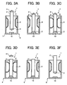
- Figs. 3A to 3F are drawings illustrating a first embodiment of procedures of separating the flange from the cylindrical substrate in the present invention.
- An electrophotographic photoreceptor 1 has a cylindrical substrate 2 including a photosensitive layer on an outer circumferential surface thereof, and a pair of flanges 3 adhesively fixed to both ends of the cylindrical substrate.
- the cylindrical substrate 2 is formed by the following steps:
- the cylindrical substrate 2 formed of the aluminium base alloy is washed by a jet water washer to remove oil adhered on the surface thereof.
- a surfactant and an ultrasonic oscillator were used together.
- the cylindrical substrate is washed with pure water for three times to completely remove the surfactant and is dried.
- the coating liquid is coated on the surface of the cylindrical substrate 2 by a dip coating method, and heated at 150 °C for 15 min to harden the resin and form an undercoat layer having a thickness of 5 ⁇ m thereon.
- the coating liquid is coated on the undercoat layer by a dip coating method, and dried at 100 °C for 10 min to form a charge generation layer thereon.
- the coating liquid is coated on the charge generation layer by a dip coating method, and dried at 120 °C for 15 min to form a charge transport layer thereon.
- the flange 3 includes a plate 3a, a shaft 3b formed on one side of the plate 3a and a boss 3c formed on the other side thereof.
- the boss 3c is inserted into the cylindrical substrate 2, and an outer circumferential surface of the boss 3c and an inner circumferential surface of the cylindrical substrate 2 are adhesively fixed with an adhesive.
- the adhered width is set at 5 mm.
- the plate 3a of the flange 3 includes two hole-shaped joints 5 with which a claw 4a of a separation jig 4 is engaged. These joints 5 are formed such that a tensile load is substantially uniformly applied to a rim of the plate 3a when the claw 4a of the separation jig 4 is engagedwith them in a separating direction (an axial direction of the cylindrical substrate 2). Specifically, the two joints 5 are symmetrically located with respect to the shaft 3b formed on the centre of the plate 3a.
- the plate 3a can include three or more joints, provided they are located thereon such that a tensile load is uniformly applied to a rim of the plate 3a when a claw of a separation jig is engaged with them in a separating direction (an axial direction of the cylindrical substrate 2). Specifically, when the plate 3a includes three joints, they are located on a concentric circle of the shaft 3b at intervals of 120°.
- the resin preferably excludes ones having a halogen atom such as polyvinylchloride.
- a fire retardant is added to an organic polymer resin as the material for the flange 3, it is preferably a non-halogen fire retardant.
- the flange 3 is adhesively fixed with the cylindrical substrate 2 with an adhesive, and the cylindrical substrate 2 is never bent.
- the adhesive is preferably an adhesive such as a cyano acrylate adhesive capable of adhering in a short time without affecting a photosensitive layer of the electrophotographic photoreceptor.
- Fig. 3A shows a status before setting an electrophotographic photoreceptor 1 in a jig 6 for grasping the electrophotographic photoreceptor.
- the jig 6 has a cylindrical jig frame 7 having one end closed and the other end open, and a doughnut-shaped elastic body 8 is formed on an inner circumferential surface of the jig frame 7.
- the elastic body 8 includes a space 9 inside, and is inflated by filling the space 9 with a fluid such as compressed air and contracted by letting the fluid out of the space 9.
- the jig frame 7 includes an opening (not shown) through which the fluid is filled into and let out of the space 9.
- the elastic body 8 is formed of a rubber sheet, such as an isoprene rubber, a butadiene rubber, a styrene-butadiene rubber, a butyl rubber, chloroprene rubber or a urethane rubber adhered to an inner circumferential surface of the jig frame 7.
- the space 9 is formed between the rubber sheet and the jig frame 7.
- the rubber sheet forming the elastic body 8 preferably has a thickness of from 1 to 8 mm.
- the closed end of the jig 6 has a grip 10 for gripping an end of the electrophotographic photoreceptor 1.
- Fig. 3B shows a status of the electrophotographic photoreceptor 1 set in the jig 6. An end of the electrophotographic photoreceptor 1 is gripped by the grip 10.
- Fig. 3C shows a status of the electrophotographic photoreceptor 1 grasped by the elastic body 8, wherein a space 9 is filled with a fluid to inflate the elastic body 8 to be pressed against the outer circumferential surface of the electrophotographic photoreceptor 1.
- Fig. 3D shows a status of the flange 3 separated from the cylindrical substrate 2, wherein the claw 4a of the separation jig 4 is engaged with the joint 5 of the flange 3 (refer to Fig. 2) to pull the flange 3 in a direction of separating the flange 3 from the cylindrical substrate 2 (along an axial direction thereof).
- the separation jig 4 engaging the claw 4a with the joint 5 is moved in an axial direction of the cylindrical substrate 2, and a variety of movers such as an air cylinder, a ball screw and a rack & pinion can be used to move the cylindrical substrate 2.
- the moving speed of the separation jig 4 can be determined in view of the operation efficiency and safety, and is preferably from 1 to 30 mm/sec.
- the moving distance thereof may be not less than an inserted length of the boss 3c of the flange 3 into the cylindrical substrate 2.
- the moving distance of the separation jig 4 may be, for example, 5 mm only to release the flange 3 from adherence to the cylindrical substrate 2, and the flange 3 may be released by other means.
- Fig. 3E shows a status of the electrophotographic photoreceptor 1 released from being grasped by the elastic body 8 which is contracted by letting the fluid out of the space 9.
- Fig. 3F shows a status of taking the electrophotographic photoreceptor 1 from which the flange 3 is removed from out of the jig 6.
- the other flange 3 may be pushed out from the other side thereof with a stick inserted from the side from which the first flange 3 is taken out or separated therefrom by setting the electrophotographic photoreceptor 1 upside down in the jig 6 and repeating the operations of Figs. 3B to 3F mentioned above.
- the electrophotographic photoreceptor 1 grasped with the elastic body 8 pressed against the outer circumferential surface thereof can be displaceable according to the pulling direction. Therefore, the flange 3 can be pulled without pressing the rim thereof against the inner circumferential surface of the cylindrical substrate 2 with an uneven pressure, and the cylindrical substrate 2 and flange 3 can be separated from each other without being damaged and can be recyclable as they are.
- the elastic body 8 preferably has a hardness of from 10 to 90, and more preferably has a hardness of from 20 to 75 when measured by a method specified in JIS K6253 using a durometer.
- the elastic body 8 has a hardness greater than 90, the cylindrical substrate 2 can be deformed when the electrophotographic photoreceptor 1 is grasped. When less than 10, it is difficult to firmly grasp the electrophotographic photoreceptor 1.
- the elastic body 8 preferably has a contact area with the electrophotographic photoreceptor 1 upon application of pressure not less than 12 cm 2 .
- a pressure against the electrophotographic photoreceptor 1 increases and the cylindrical substrate 2 can be deformed.
- FIG. 4A to 4D A second embodiment of procedures of separating the flange from the cylindrical substrate in the present invention will be explained according to Figs. 4A to 4D.
- a part that is the same part as previously explained in the other embodiment has the same reference numeral and an explanation thereof is omitted, which is same in the following other embodiments.
- An electrophotographic photoreceptor 1 in Figs. 4A to 4D is the same electrophotographic photoreceptor 1 in Figs. 3A to 3F, and a flange 3 is adhesively fixed on each of both ends of the cylindrical substrate 2.
- the flange 3 has a pair of joints 5 (refer to Fig. 1).
- a jig 11 for grasping has a different structure from that of the jig 6 for grasping in Figs. 3A to 3F.
- the jig 11 includes a jig frame 12 with both ends open, a doughnut-shaped elastic body 8 formed on an inner circumferential surface thereof and including a space 9 inside, and a support 13 supporting the electrophotographic photoreceptor 1.
- the electrophotographic photoreceptor 1 is located on the support 13 so that it is set in the jig 11.
- Fig. 4B shows a status of the electrophotographic photoreceptor 1 grasped by the elastic body 8, wherein a space 9 is filled with a fluid to inflate the elastic body 8 to be pressed against the outer circumferential surface of the electrophotographic photoreceptor 1.
- Fig. 4C shows a status of the flange 3 separated from the cylindrical substrate 2, wherein the claw 4a of the separation jig 4 is engaged with the joint 5 of the flange 3 (refer to Fig. 2) to pull the flange 3 in a direction of separating the flange 3 from the cylindrical substrate 2 (along an axial direction thereof).
- FIG. 4D shows a status of the electrophotographic photoreceptor 1 released from being grasped by the elastic body 8 which is contracted by letting the fluid out of the space 9.
- An electrophotographic photoreceptor 1 in Figs. 5A to 5F is the same electrophotographic photoreceptor 1 in Figs. 3A to 3F, and a flange 3 is adhesively fixed on each of both ends of the cylindrical substrate 2.
- the flange 3 has a pair of joints 5 (refer to Fig. 1).
- a jig 21 for grasping has a different structure from those of the jigs 6 and 11 for grasping in Figs. 3 and 4 respectively.
- the jig 21 includes a cylindrical jig frame 22 having one end closed and the other end open, plural arc-shaped elastic bodies 23 separately located on an inner circumferential surface of the jig frame 22 and a mover 24 capable of moving the elastic body 23 toward the center of the jig frame 22 and backward.
- the closed end of the jig 21 has a grip 10 for gripping an end of the electrophotographic photoreceptor 1.
- Fig. 5A shows a status before setting an electrophotographic photoreceptor 1 in a jig 21 for grasping the electrophotographic photoreceptor.
- the elastic body 23 is located apart from the center of the jig frame 22.
- Fig. 5B shows a status of the electrophotographic photoreceptor 1 set in the jig 21. An end of the electrophotographic photoreceptor 1 is gripped by the grip 10.
- Fig. 5C shows a status of the elastic body 23 moved toward the center of the jig frame 22 by the mover 24.
- the elastic body 23 moved toward the center of the jig frame 22 is pressed against an outer circumferential surface of the electrophotographic photoreceptor 1 to grasp the electrophotographic photoreceptor 1.
- Fig. 5D shows a status of the flange 3 separated from the cylindrical substrate 2, wherein the claw 4a of the separation jig 4 is engaged with the joint 5 of the flange 3 (refer to Fig. 2) to pull the flange 3 in a direction of separating the flange 3 from the cylindrical substrate 2 (along an axial direction thereof).
- Fig. 5E shows a status of the electrophotographic photoreceptor 1 released from being grasped by the elastic body 23 which is moved by the mover 24 from the center of the jig frame 22.
- Fig. 5F shows a status of taking the electrophotographic photoreceptor 1 from which the flange 3 is removed from out of the jig 21.
- the other flange 3 may be pushed out from the other side thereof with a stick inserted from the side from which the first flange 3 is taken out or separated therefrom by setting the electrophotographic photoreceptor 1 upside down in the jig 21 and repeating the operations of Figs. 5B to Fig. 5F mentioned above.
- An electrophotographic photoreceptor 31 includes a cylindrical substrate 2 and a pair of flanges 32 adhesively fixed to both ends of the cylindrical substrate 2.
- the flange 32 includes a plate 3a, a shaft 3b formed on one side of the plate 3a and a boss 3c formed on the other side thereof.
- a concave joint 33 is formed on the plate 3a.
- the electrophotographic photoreceptor 31 When the flange 32 is separated from the cylindrical substrate 2 of the electrophotographic photoreceptor 31, the electrophotographic photoreceptor 31 is grasped in jig 6, 11 or 21 of the first, second or third embodiment of procedures of separating the flange from the cylindrical substrate in the present invention respectively, a claw 4a of a separation jig 4 is engaged with the joint 33 of the flange 32, and the flange 32 is pulled in a direction of separating the flange 32 from the cylindrical substrate 2 (along an axial direction thereof).
- cylindrical substrate 2 and flange 32 are separated from each other without being damaged, and they are recyclable as they are.
- An electrophotographic photoreceptor 41 includes a cylindrical substrate 2 and a pair of flanges 42 adhesively fixed to both ends of the cylindrical substrate 2.
- the flange 32 includes a plate 3a, a shaft 3b formed on one side of the plate 3a and a boss 3c formed on the other side thereof.
- a convex joint 43 is formed on the plate 3a.
- the electrophotographic photoreceptor 41 When the flange 42 is separated from the cylindrical substrate 2 of the electrophotographic photoreceptor 41, the electrophotographic photoreceptor 41 is grasped in jig 6, 11 or 21 of the first, second or third embodiment of procedures of separating the flange from the cylindrical substrate in the present invention respectively, a claw 4a of a separation jig 4 is engaged with the joint 43 of the flange 42, and the flange 42 is pulled in a direction of separating the flange 42 from the cylindrical substrate 2 (along an axial direction thereof).
- cylindrical substrate 2 and flange 42 are separated from each other without being damaged, and they are recyclable as they are.
- the electrophotographic photoreceptor 1 of the first embodiment was used, and the flange 3 was adhered to the cylindrical substrate 2 with ARONALPHA (Trademark) from Toagosei Co., Ltd. An adhered width of the flange to the cylindrical substrate 2 was 5 mm.
- the electrophotographic photoreceptor 1 was grasped by the jig 6 in Figs. 3A to 3F.
- the jig 6 uses a method of grasping the electrophotographic photoreceptor 1 by filling the space 9 of the elastic body 8 with compressed air to inflate the elastic body 8, and the compressed air had a pressure of 10,000 Pa.
- the elastic body had a hardness of 35 when measured by a method specified in JIS K6253 using a durometer.
- the claw 4a of the separation jig 4 was inserted into the joint 5 of the flange 3, and the claw 4a was hooked on the joint 5 and the separation jig 4 was raised by an air cylinder. Consequently, the flange 3 could easily be separated from the cylindrical substrate 2.
- a vinylchloride stick having an outer diameter of 30 mm and a length of 500 mm was inserted into the electrophotographic photoreceptor 1 from the side from which the flange was removed, and the flange 3 on the other side of the electrophotographic photoreceptor 1 was knocked out.
- the coated film over the electrophotographic photoreceptor 1 from which the flange 3 was released was removed with tetrahydrofuran and N-methyl-2-pyrrolidone. Then, the size of the cylindrical substrate 2 was measured by a measurer from Mitsutoyo Corp. Further, the total deflection amount of the cylindrical substrate 2 was measured by a deflection measurer from Ricoh Company, Ltd.
- the cylindrical substrate is judged to be "in standard” if it is within ⁇ 0.07mm of the designed dimensions.
- the flange is judged to be “in standard” if it is within ⁇ 0.05mm of the designed dimensions.
- Example 1 The procedures for evaluations of the cylindrical substrate and flange in Example 1 were repeated except for not using the jig 6 for grasping the electrophotographic photoreceptor 1.
- Example 1 The procedures for evaluations of the cylindrical substrate and flange in Example 1 were repeated except that the flange did not have a joint and a driver was slowly inserted into a gap between the flange and cylindrical substrate 2 to remove the flange therefrom.
- Example 1 Normal In standard Normal In standard Example 2 Normal In standard Jointslightly deformed In standard Example 3 Normal In standard Joint slightly deformed In standard Example 4 Normal In standard Normal In standard Comparative Example 1 Slightly deformed Deformed, rejected Deformed Rejected Comparative Example 2 Grasped part concave Deformed, rejected Deformed Rejected
Landscapes
- Physics & Mathematics (AREA)
- General Physics & Mathematics (AREA)
- Photoreceptors In Electrophotography (AREA)
- Electrophotography Configuration And Component (AREA)
- Discharging, Photosensitive Material Shape In Electrophotography (AREA)
Abstract
Description
- The present invention relates to an electrophotographic photoreceptor and a method of recycling an electrophotographic photoreceptor.
- An electrophotographic photoreceptor is formed of an electroconductive cylindrical substrate, an organic or inorganic photosensitive layer formed thereon and flanges fixed on both ends thereof. The flange has a shaft, and an electrophotographic photoreceptor in an image forming apparatus is rotated centering around the shaft. The flange is not only a rotation center of an electrophotographic photoreceptor but also has a function of earthing. Since tolerance between the flange and cylindrical substrate causes abnormal images, the flange is firmly fixed to the cylindrical substrate with an adhesive and the like.
- Recently, to save resources, it is demanded that the cylindrical substrate and flange of an electrophotographic are recycled.
- To recycle the cylindrical substrate and flange, the flange fixed to the cylindrical substrate has to be removed therefrom. When the flange can be removed from the cylindrical substrate without damaging them, they can be used as they are. "they can be used as they are" means that the cylindrical substrate and flange separated from each other are recycled as they are, and not that the cylindrical substrate and flange separated from each other are returned to materials by melting them down or the like method.
- Japanese Laid-Open Patent Publication No. 10-115938 discloses a method of quenching an adhesive to be peeled with a cooling medium such as liquid nitrogen as an invention of recycling a cylindrical substrate and a flange without damaging them.
- However, the invention disclosed therein needs a cooling medium such as liquid nitrogen, and the cooling medium is difficult to store and handle.
- Because of these reasons, a need exists for an electrophotographic photoreceptor including a cylindrical substrate and a flange easily separable from each other without damaging them and recyclable as they are.
- Accordingly, an object of the present invention is to provide an electrophotographic photoreceptor including a cylindrical substrate and a flange easily separable from each other without damaging them and recyclable as they are.
- Another object of the present invention is to provide a method of easily separating a cylindrical substrate and a flange of an electrophotographic photoreceptor from each other without damaging them, and recycling them as they are.
- Briefly these objects and other objects of the present invention as hereinafter will become more readily apparent can be attained by an electrophotographic photoreceptor including a cylindrical substrate including a photosensitive layer on an outer surface thereof; and a flange adhesively fixed to each of both ends of the cylindrical substrate, wherein the flange has a joint with which a separation jig is engageable to apply a tensile load in a direction of separating the flange from the cylindrical substrate.
- The flange preferably has two or more joints located thereon such that the tensile load may be uniformly applied to a rim thereof.
- Another aspect of the present invention is to provide a method of recycling the electrophotographic photoreceptor, including filling an elastic body with a fluid to inflate and contact the elastic body to an outer circumferential surface of the electrophotographic photoreceptor upon application of pressure to grasp the electrophotographic photoreceptor in a jig; and
engaging the separation jig with the joint to pull the flange in a direction of separating the flange from the cylindrical substrate. - Still another aspect of the present invention is to provide a method of recycling the electrophotographic photoreceptor, including moving a movable elastic body to contact the elastic body to an outer circumferential surface of the electrophotographic photoreceptor upon application of pressure to grasp the electrophotographic photoreceptor in a jig; and engaging the separation jig with the joint to pull the flange in a direction of separating the flange from the cylindrical substrate.
- These and other objects, features and advantages of the present invention will become apparent upon consideration of the following description of the preferred embodiments of the present invention taken in conjunction with the accompanying drawings.
- Various other objects, features and attendant advantages of the present invention will be more fully appreciated as the same becomes better understood from the detailed description when considered in connection with the accompanying drawings in which like reference characters designate like corresponding parts throughout and wherein:
- Fig. 1 is a schematic longitudinal sectional view illustrating a first embodiment of the electrophotographic photoreceptor of the present invention;
- Fig. 2 is a schematic longitudinal sectional view illustrating a separation jig is engaged with a flange of the first embodiment of the electrophotographic photoreceptor in Fig. 1;
- Figs. 3A to 3F are drawings illustrating a first embodiment of procedures of separating the flange from the cylindrical substrate in the present invention;
- Figs. 4A to 4D are drawings illustrating a second embodiment of procedures of separating the flange from the cylindrical substrate in the present invention;
- Figs. 5A to 5F are drawings illustrating a third embodiment of procedures of separating the flange from the cylindrical substrate in the present invention;
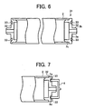
- Fig. 6 is a schematic longitudinal sectional view illustrating a second embodiment of the electrophotographic photoreceptor of the present invention;
- Fig. 7 is a schematic longitudinal sectional view illustrating a separation jig engaged with a flange of the second embodiment of the electrophotographic photoreceptor in Fig. 6;
- Fig. 8 is a schematic longitudinal sectional view illustrating a third embodiment of the electrophotographic photoreceptor of the present invention; and
- Fig. 9 is a schematic longitudinal sectional view illustrating a separation jig engaged with a flange of the third embodiment of the electrophotographic photoreceptor in Fig. 8.
-
- Generally, the present invention provides an electrophotographic photoreceptor including a cylindrical substrate and a flange easily separable from each other without damaging them and recyclable as they are, and a method of easily separating a cylindrical substrate and a flange of an electrophotographic photoreceptor from each other without damaging them, and recycling them as they are.
- The electrophotographic photoreceptor of the present invention includes a cylindrical substrate including a photosensitive layer on an outer circumferential surface thereof; and a flange adhesively fixed to each of both ends of the cylindrical substrate, wherein the flange has a joint with which a separation jig is engaged to apply a tensile load in a direction of separating the flange from the cylindrical substrate.
- Therefore, the separation jig grasps the electrophotographic photoreceptor so as not to bedeformed, being engaged with the joint formed on the flange to pull the flange in the direction of separating the flange from the cylindrical substrate. The flange and cylindrical substrate are easily separated from each other without being damaged, and they are recyclable as they are. In addition, the flange can simply be prepared at low cost because of having a joint.
- The flange has two or more joints located thereon such that the tensile load is substantially uniformly applied to a rim thereof.
- Therefore, when the flange is pulled to be separated from the cylindrical substrate, the rim of the flange can be prevented from pressing against an inner circumferential surface of the cylindrical surface with an uneven pressure, and damages of the flange and cylindrical substrate can be more reliably prevented.
- A method of recycling the electrophotographic photoreceptor of the present invention includes filling an elastic body with a fluid to inflate and contact the elastic body to an outer circumferential surface of the electrophotographic photoreceptor upon application of pressure to grasp the electrophotographic photoreceptor in a jig; and engaging the separation jig to the joint to pull the flange in a direction of separating the flange from the cylindrical substrate.
- Therefore, the electrophotographic photoreceptor is grasped in a jig, and the separation jig is engaged with the joint formed on the flange and pulls the flange in a direction of separating the flange from the cylindrical substrate. When the electrophotographic photoreceptor is grasped in a jig, since an inflated elastic body in which a fluid is filled is pressed against an outer circumferential surface of the electrophotographic photoreceptor, a pressure to grasp the electrophotographic photoreceptor is almost uniformly applied thereto and the electrophotographic photoreceptor is grasped without deformation of the cylindrical substrate. When the flange is pulled in the direction of separating the flange from the cylindrical substrate after the elastic body is pressed against the outer circumferential surface of the electrophotographic photoreceptor to grasp the electrophotographic photoreceptor, the electrophotographic photoreceptor grasped with the elastic body pressed against the outer circumferential surface thereof can be displaceable according to the pulling direction. Therefore, the flange can be pulled without pressing the rim thereof against the inner circumferential surface of the cylindrical substrate with an uneven pressure, and the cylindrical substrate and flange can be separated from each other without being damaged and can be recyclable as they are. The operation of separating the flange from the cylindrical substrate with the jig for grasping and the separation jig can easily be performed.
- Another method of recycling the electrophotographic photoreceptor according of the present invention includes moving a movable elastic body to contact the elastic body to an outer circumferential surface of the electrophotographic photoreceptor upon application of pressure to grasp the electrophotographic photoreceptor in a jig; and engaging the separation jig with the joint to pull the flange in a direction of separating the flange from the cylindrical substrate.
- Therefore, the electrophotographic photoreceptor is grasped in a jig, and the separation jig is engaged with the joint formed on the flange and pulls the flange in a direction of separating the flange from the cylindrical substrate. When the electrophotographic photoreceptor is grasped in a jig, since a movable elastic body is moved to be pressed against an outer circumferential surface of the electrophotographic photoreceptor, a pressure to grasp the electrophotographic photoreceptor is almost uniformly applied thereto and the electrophotographic photoreceptor is grasped without deformation of the cylindrical substrate. When the flange is pulled in the direction of separating the flange from the cylindrical substrate after the elastic body is pressed against the outer circumferential surface of the electrophotographic photoreceptor to grasp the electrophotographic photoreceptor, the electrophotographic photoreceptor grasped with the elastic body pressed against the outer circumferential surface thereof can be displaceable according to the pulling direction. Therefore, the flange can be pulled without pressing the rim thereof against the inner circumferential surface with an uneven pressure, and the cylindrical substrate and flange can be separated from each other without being damaged and can be recyclable as they are. The operation of separating the flange from the cylindrical substrate with the jig for grasping and the separation jig can easily be performed.
- The elastic body has a hardness of from 10 to 90 when measured by a method specified in JIS K6253 using a durometer.
- Therefore, when the electrophotographic photoreceptor is grasped with the elastic body pressed against the outer circumferential surface thereof, deformation of the cylindrical substrate due to too high a hardness of the elastic body can be prevented.
- In addition, the elastic body has a contact area with the electrophotographic photoreceptor upon application of pressure not less than 12 cm2.
- Therefore, when the electrophotographic photoreceptor is grasped with the elastic body pressed against the outer circumferential surface thereof, increase of the pressure against the electrophotographic photoreceptor is prevented and deformation of the cylindrical substrate due to the pressure can be prevented.
- Fig. 1 is a schematic longitudinal sectional view illustrating a first embodiment of the electrophotographic photoreceptor of the present invention, Fig. 2 is a schematic longitudinal sectional view illustrating a separation jig engaged with a flange of the first embodiment of the electrophotographic photoreceptor in Fig. 1, and Figs. 3A to 3F are drawings illustrating a first embodiment of procedures of separating the flange from the cylindrical substrate in the present invention.
- An
electrophotographic photoreceptor 1 has acylindrical substrate 2 including a photosensitive layer on an outer circumferential surface thereof, and a pair offlanges 3 adhesively fixed to both ends of the cylindrical substrate. - The
cylindrical substrate 2 is formed by the following steps: - forming a cylinder from an aluminium base alloy based on JIS A3100, having a length of 340 mm, an outer diameter of 60.2 mm and an inner diameter of 57.5 mm; and
- turning the cylinder on a lathe to have an outer diameter
of 60.0 mm to form the
cylindrical substrate 2 formed of the aluminium base alloy. -
- Then, the
cylindrical substrate 2 formed of the aluminium base alloy is washed by a jet water washer to remove oil adhered on the surface thereof. When washed, a surfactant and an ultrasonic oscillator were used together. After being washed with jet water, the cylindrical substrate is washed with pure water for three times to completely remove the surfactant and is dried. - Next, the following materials are mixed to prepare a coating liquid:
Titanium dioxide 20 parts by weight Alkyd resin 10 parts by weight Melamine resin 10 parts by weight Methyl ethyl ketone 60 parts by weight - The coating liquid is coated on the surface of the
cylindrical substrate 2 by a dip coating method, and heated at 150 °C for 15 min to harden the resin and form an undercoat layer having a thickness of 5 µm thereon. - Then, the following materials are mixed to prepare a coating liquid for forming a charge generation layer:


- The coating liquid is coated on the undercoat layer by a dip coating method, and dried at 100 °C for 10 min to form a charge generation layer thereon.
- Further, the following materials are mixed to prepare a coating liquid for forming a charge transport layer:
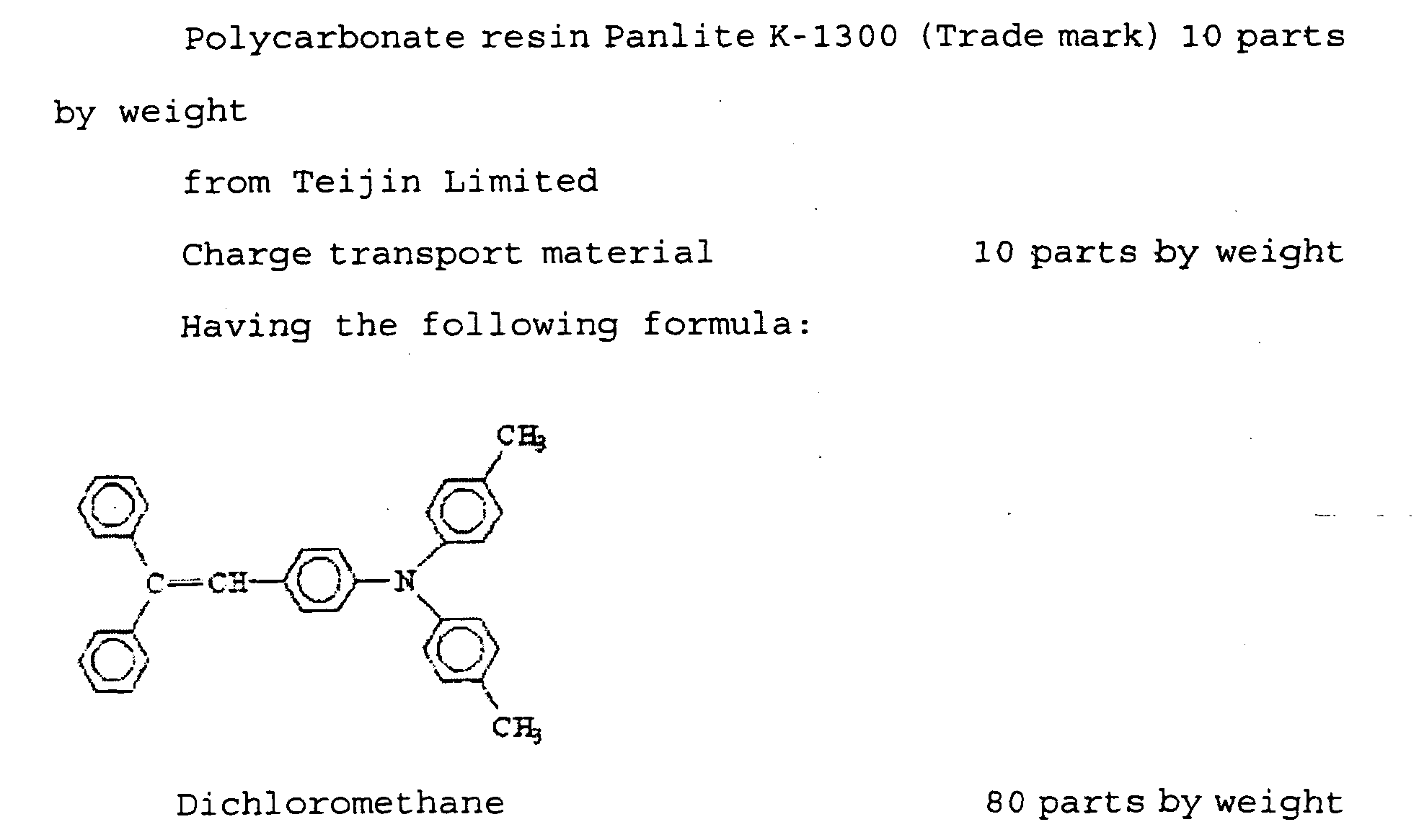
- The coating liquid is coated on the charge generation layer by a dip coating method, and dried at 120 °C for 15 min to form a charge transport layer thereon.
- The
flange 3 includes aplate 3a, ashaft 3b formed on one side of theplate 3a and aboss 3c formed on the other side thereof. Theboss 3c is inserted into thecylindrical substrate 2, and an outer circumferential surface of theboss 3c and an inner circumferential surface of thecylindrical substrate 2 are adhesively fixed with an adhesive. The adhered width is set at 5 mm. - The
plate 3a of theflange 3 includes two hole-shapedjoints 5 with which aclaw 4a of aseparation jig 4 is engaged. Thesejoints 5 are formed such that a tensile load is substantially uniformly applied to a rim of theplate 3a when theclaw 4a of theseparation jig 4 is engagedwith them in a separating direction (an axial direction of the cylindrical substrate 2). Specifically, the twojoints 5 are symmetrically located with respect to theshaft 3b formed on the centre of theplate 3a. - The
plate 3a can include three or more joints, provided they are located thereon such that a tensile load is uniformly applied to a rim of theplate 3a when a claw of a separation jig is engaged with them in a separating direction (an axial direction of the cylindrical substrate 2). Specifically, when theplate 3a includes three joints, they are located on a concentric circle of theshaft 3b at intervals of 120°. - Various polymers such as an ABS resin, a polyacetal resin and a PBT resin can be used as a material for the
flange 3. Reflecting the recent environment protection, the resin preferably excludes ones having a halogen atom such as polyvinylchloride. When a fire retardant is added to an organic polymer resin as the material for theflange 3, it is preferably a non-halogen fire retardant. - The
flange 3 is adhesively fixed with thecylindrical substrate 2 with an adhesive, and thecylindrical substrate 2 is never bent. The adhesive is preferably an adhesive such as a cyano acrylate adhesive capable of adhering in a short time without affecting a photosensitive layer of the electrophotographic photoreceptor. - The process of separating the
flange 3 from thecylindrical substrate 2 will be explained according to Figs. 3A to 3F. - Fig. 3A shows a status before setting an
electrophotographic photoreceptor 1 in ajig 6 for grasping the electrophotographic photoreceptor. Thejig 6 has a cylindrical jig frame 7 having one end closed and the other end open, and a doughnut-shapedelastic body 8 is formed on an inner circumferential surface of the jig frame 7. Theelastic body 8 includes aspace 9 inside, and is inflated by filling thespace 9 with a fluid such as compressed air and contracted by letting the fluid out of thespace 9. The jig frame 7 includes an opening (not shown) through which the fluid is filled into and let out of thespace 9. Theelastic body 8 is formed of a rubber sheet, such as an isoprene rubber, a butadiene rubber, a styrene-butadiene rubber, a butyl rubber, chloroprene rubber or a urethane rubber adhered to an inner circumferential surface of the jig frame 7. Thespace 9 is formed between the rubber sheet and the jig frame 7. The rubber sheet forming theelastic body 8 preferably has a thickness of from 1 to 8 mm. The closed end of thejig 6 has agrip 10 for gripping an end of theelectrophotographic photoreceptor 1. - Fig. 3B shows a status of the
electrophotographic photoreceptor 1 set in thejig 6. An end of theelectrophotographic photoreceptor 1 is gripped by thegrip 10. - Fig. 3C shows a status of the
electrophotographic photoreceptor 1 grasped by theelastic body 8, wherein aspace 9 is filled with a fluid to inflate theelastic body 8 to be pressed against the outer circumferential surface of theelectrophotographic photoreceptor 1. - Fig. 3D shows a status of the
flange 3 separated from thecylindrical substrate 2, wherein theclaw 4a of theseparation jig 4 is engaged with thejoint 5 of the flange 3 (refer to Fig. 2) to pull theflange 3 in a direction of separating theflange 3 from the cylindrical substrate 2 (along an axial direction thereof). - When the
flange 3 is separated, theseparation jig 4 engaging theclaw 4a with the joint 5 is moved in an axial direction of thecylindrical substrate 2, and a variety of movers such as an air cylinder, a ball screw and a rack & pinion can be used to move thecylindrical substrate 2. The moving speed of theseparation jig 4 can be determined in view of the operation efficiency and safety, and is preferably from 1 to 30 mm/sec. The moving distance thereof may be not less than an inserted length of theboss 3c of theflange 3 into thecylindrical substrate 2. However, when the inserted length of theboss 3c of theflange 3 into thecylindrical substrate 2 is, for example, 20 mm, the moving distance of theseparation jig 4 may be, for example, 5 mm only to release theflange 3 from adherence to thecylindrical substrate 2, and theflange 3 may be released by other means. - Fig. 3E shows a status of the
electrophotographic photoreceptor 1 released from being grasped by theelastic body 8 which is contracted by letting the fluid out of thespace 9. - Fig. 3F shows a status of taking the
electrophotographic photoreceptor 1 from which theflange 3 is removed from out of thejig 6. - After a
flange 3 is taken out from a side of theelectrophotographic photoreceptor 1, theother flange 3 may be pushed out from the other side thereof with a stick inserted from the side from which thefirst flange 3 is taken out or separated therefrom by setting theelectrophotographic photoreceptor 1 upside down in thejig 6 and repeating the operations of Figs. 3B to 3F mentioned above. - When the
space 9 of theelastic body 8 is filled with a fluid to inflate theelastic body 8 to be pressed against the outer circumferential of theelectrophotographic photoreceptor 1 as shown in Fig 3C, a pressure of theelastic body 8 grasping theelectrophotographic photoreceptor 1 is almost uniformly applied thereto, and thecylindrical substrate 2 of theelectrophotographic photoreceptor 1 is grasped without being deformed. Further, when theflange 3 is pulled in the direction of separating theflange 3 from thecylindrical substrate 2 after theelastic body 8 is pressed against the outer circumferential surface of theelectrophotographic photoreceptor 1 to grasp theelectrophotographic photoreceptor 1, theelectrophotographic photoreceptor 1 grasped with theelastic body 8 pressed against the outer circumferential surface thereof can be displaceable according to the pulling direction. Therefore, theflange 3 can be pulled without pressing the rim thereof against the inner circumferential surface of thecylindrical substrate 2 with an uneven pressure, and thecylindrical substrate 2 andflange 3 can be separated from each other without being damaged and can be recyclable as they are. - The
elastic body 8 preferably has a hardness of from 10 to 90, and more preferably has a hardness of from 20 to 75 when measured by a method specified in JIS K6253 using a durometer. When theelastic body 8 has a hardness greater than 90, thecylindrical substrate 2 can be deformed when theelectrophotographic photoreceptor 1 is grasped. When less than 10, it is difficult to firmly grasp theelectrophotographic photoreceptor 1. - In addition, the
elastic body 8 preferably has a contact area with theelectrophotographic photoreceptor 1 upon application of pressure not less than 12 cm2. When less than 12 cm2, a pressure against theelectrophotographic photoreceptor 1 increases and thecylindrical substrate 2 can be deformed. - A second embodiment of procedures of separating the flange from the cylindrical substrate in the present invention will be explained according to Figs. 4A to 4D. A part that is the same part as previously explained in the other embodiment has the same reference numeral and an explanation thereof is omitted, which is same in the following other embodiments.
- An
electrophotographic photoreceptor 1 in Figs. 4A to 4D is thesame electrophotographic photoreceptor 1 in Figs. 3A to 3F, and aflange 3 is adhesively fixed on each of both ends of thecylindrical substrate 2. Theflange 3 has a pair of joints 5 (refer to Fig. 1). - In this embodiment, a
jig 11 for grasping has a different structure from that of thejig 6 for grasping in Figs. 3A to 3F. Thejig 11 includes ajig frame 12 with both ends open, a doughnut-shapedelastic body 8 formed on an inner circumferential surface thereof and including aspace 9 inside, and asupport 13 supporting theelectrophotographic photoreceptor 1. - When the
flange 3 is separated from thecylindrical substrate 2, at first, as Fig. 4A shows, theelectrophotographic photoreceptor 1 is located on thesupport 13 so that it is set in thejig 11. - Fig. 4B shows a status of the
electrophotographic photoreceptor 1 grasped by theelastic body 8, wherein aspace 9 is filled with a fluid to inflate theelastic body 8 to be pressed against the outer circumferential surface of theelectrophotographic photoreceptor 1. - Fig. 4C shows a status of the
flange 3 separated from thecylindrical substrate 2, wherein theclaw 4a of theseparation jig 4 is engaged with thejoint 5 of the flange 3 (refer to Fig. 2) to pull theflange 3 in a direction of separating theflange 3 from the cylindrical substrate 2 (along an axial direction thereof). - Fig. 4D shows a status of the
electrophotographic photoreceptor 1 released from being grasped by theelastic body 8 which is contracted by letting the fluid out of thespace 9. A third embodiment of procedures of separating the flange from the cylindrical substrate in the present invention will be explained according to Figs. 5A to 5F. Anelectrophotographic photoreceptor 1 in Figs. 5A to 5F is thesame electrophotographic photoreceptor 1 in Figs. 3A to 3F, and aflange 3 is adhesively fixed on each of both ends of thecylindrical substrate 2. Theflange 3 has a pair of joints 5 (refer to Fig. 1). - In this embodiment, a
jig 21 for grasping has a different structure from those of thejigs jig 21 includes acylindrical jig frame 22 having one end closed and the other end open, plural arc-shapedelastic bodies 23 separately located on an inner circumferential surface of thejig frame 22 and amover 24 capable of moving theelastic body 23 toward the center of thejig frame 22 and backward. The closed end of thejig 21 has agrip 10 for gripping an end of theelectrophotographic photoreceptor 1. - Fig. 5A shows a status before setting an
electrophotographic photoreceptor 1 in ajig 21 for grasping the electrophotographic photoreceptor. Theelastic body 23 is located apart from the center of thejig frame 22. - Fig. 5B shows a status of the
electrophotographic photoreceptor 1 set in thejig 21. An end of theelectrophotographic photoreceptor 1 is gripped by thegrip 10. - Fig. 5C shows a status of the
elastic body 23 moved toward the center of thejig frame 22 by themover 24. Theelastic body 23 moved toward the center of thejig frame 22 is pressed against an outer circumferential surface of theelectrophotographic photoreceptor 1 to grasp theelectrophotographic photoreceptor 1. - Fig. 5D shows a status of the
flange 3 separated from thecylindrical substrate 2, wherein theclaw 4a of theseparation jig 4 is engaged with thejoint 5 of the flange 3 (refer to Fig. 2) to pull theflange 3 in a direction of separating theflange 3 from the cylindrical substrate 2 (along an axial direction thereof). - Fig. 5E shows a status of the
electrophotographic photoreceptor 1 released from being grasped by theelastic body 23 which is moved by themover 24 from the center of thejig frame 22. - Fig. 5F shows a status of taking the
electrophotographic photoreceptor 1 from which theflange 3 is removed from out of thejig 21. - After a
first flange 3 is taken out from a side of theelectrophotographic photoreceptor 1, theother flange 3 may be pushed out from the other side thereof with a stick inserted from the side from which thefirst flange 3 is taken out or separated therefrom by setting theelectrophotographic photoreceptor 1 upside down in thejig 21 and repeating the operations of Figs. 5B to Fig. 5F mentioned above. - A second embodiment of the electrophotographic photoreceptor of the present invention will be explained according to Figs. 6 and 7. An
electrophotographic photoreceptor 31 includes acylindrical substrate 2 and a pair offlanges 32 adhesively fixed to both ends of thecylindrical substrate 2. Theflange 32 includes aplate 3a, ashaft 3b formed on one side of theplate 3a and aboss 3c formed on the other side thereof. Instead of the hole-shapedjoints 5 of the first embodiment, a concave joint 33 is formed on theplate 3a. - When the
flange 32 is separated from thecylindrical substrate 2 of theelectrophotographic photoreceptor 31, theelectrophotographic photoreceptor 31 is grasped injig claw 4a of aseparation jig 4 is engaged with the joint 33 of theflange 32, and theflange 32 is pulled in a direction of separating theflange 32 from the cylindrical substrate 2 (along an axial direction thereof). - Therefore, the
cylindrical substrate 2 andflange 32 are separated from each other without being damaged, and they are recyclable as they are. - A third embodiment of the electrophotographic photoreceptor of the present invention will be explained according to Figs. 8 and 9. An
electrophotographic photoreceptor 41 includes acylindrical substrate 2 and a pair offlanges 42 adhesively fixed to both ends of thecylindrical substrate 2. Theflange 32 includes aplate 3a, ashaft 3b formed on one side of theplate 3a and aboss 3c formed on the other side thereof. Instead of the hole-shapedjoints 5 of the first embodiment, a convex joint 43 is formed on theplate 3a. - When the
flange 42 is separated from thecylindrical substrate 2 of theelectrophotographic photoreceptor 41, theelectrophotographic photoreceptor 41 is grasped injig claw 4a of aseparation jig 4 is engaged with the joint 43 of theflange 42, and theflange 42 is pulled in a direction of separating theflange 42 from the cylindrical substrate 2 (along an axial direction thereof). - Therefore, the
cylindrical substrate 2 andflange 42 are separated from each other without being damaged, and they are recyclable as they are. - Having generally described this invention, further understanding can be obtained by reference to certain specific examples which are provided herein for the purpose of illustration only and are not intended to be limiting.
- The
electrophotographic photoreceptor 1 of the first embodiment was used, and theflange 3 was adhered to thecylindrical substrate 2 with ARONALPHA (Trademark) from Toagosei Co., Ltd. An adhered width of the flange to thecylindrical substrate 2 was 5 mm. Theelectrophotographic photoreceptor 1 was grasped by thejig 6 in Figs. 3A to 3F. Thejig 6 uses a method of grasping theelectrophotographic photoreceptor 1 by filling thespace 9 of theelastic body 8 with compressed air to inflate theelastic body 8, and the compressed air had a pressure of 10,000 Pa. The elastic body had a hardness of 35 when measured by a method specified in JIS K6253 using a durometer. - Next, as shown in Fig. 2, the
claw 4a of theseparation jig 4 was inserted into thejoint 5 of theflange 3, and theclaw 4a was hooked on the joint 5 and theseparation jig 4 was raised by an air cylinder. Consequently, theflange 3 could easily be separated from thecylindrical substrate 2. - After the
flange 3 on one side of theelectrophotographic photoreceptor 1 was removed, the compressed air in thespace 9 was released therefrom to release theelectrophotographic photoreceptor 1 from being grasped. - Next, a vinylchloride stick having an outer diameter of 30 mm and a length of 500 mm was inserted into the
electrophotographic photoreceptor 1 from the side from which the flange was removed, and theflange 3 on the other side of theelectrophotographic photoreceptor 1 was knocked out. - Next, the coated film over the
electrophotographic photoreceptor 1 from which theflange 3 was released was removed with tetrahydrofuran and N-methyl-2-pyrrolidone. Then, the size of thecylindrical substrate 2 was measured by a measurer from Mitsutoyo Corp. Further, the total deflection amount of thecylindrical substrate 2 was measured by a deflection measurer from Ricoh Company, Ltd. - Damages and deformations of both of the
flanges 3 were visually observed and the sizes thereof were measured by three-dimensional measurer from Mitsutoyo Corp. - The cylindrical substrate is judged to be "in standard" if it is within ± 0.07mm of the designed dimensions. The flange is judged to be "in standard" if it is within ± 0.05mm of the designed dimensions.
- The procedures for evaluations of the cylindrical substrate and flange in Example 1 were repeated except for using the
flange 32 in Figs. 6 and 7 instead of theflange 3. - The procedures for evaluations of the cylindrical substrate and flange in Example 1 were repeated except for using the
flange 42 in Figs. 8 and 9 instead of theflange 3. - The procedures for evaluations of the cylindrical substrate and flange in Example 1 were repeated except for using the
jig 21 in Figs. 3A to 3F instead of the jig. 6 - The procedures for evaluations of the cylindrical substrate and flange in Example 1 were repeated except for not using the
jig 6 for grasping theelectrophotographic photoreceptor 1. - The procedures for evaluations of the cylindrical substrate and flange in Example 1 were repeated except that the flange did not have a joint and a driver was slowly inserted into a gap between the flange and
cylindrical substrate 2 to remove the flange therefrom. - The evaluation results of Examples 1 to 4 and Comparative Examples 1 to 2 are shown in Table 1.
Visual observation of photoreceptor after flange is removed Size of cylindrical substrate Appearance of flange Size of flange Example 1 Normal In standard Normal In standard Example 2 Normal In standard Jointslightly deformed In standard Example 3 Normal In standard Joint slightly deformed In standard Example 4 Normal In standard Normal In standard Comparative Example 1 Slightly deformed Deformed, rejected Deformed Rejected Comparative Example 2 Grasped part concave Deformed, rejected Deformed Rejected - According to the evaluation results in Table 1, in Example 1 and 4, both the cylindrical substrates and the flanges were normal and in standard.
- In Examples 2 and 3, the joints of the flanges were slightly deformed. However, the joint has nothing to do with the quality of an electrophotographic photoreceptor and could be recyclable.
- On the contrary, both the cylindrical substrates and the flanges were deformed in Comparative Examples 1 and 2, and could not be recyclable as they are.
- This document claims priority and contains subject matter related to Japanese Patent Application No. 2003-375720 filed on November 5, 2003, incorporated herein by reference.
- Having now fully described the invention, it will be apparent to one of ordinary skill in the art that many changes and modifications can be made thereto without departing from the spirit and scope of the invention as set forth therein.
Claims (9)
- An electrophotographic photoreceptor (1,31,41) comprising:wherein the flange (3,32,42)has a joint (5,33,43)with which a separation jig (4) is engageable to apply a tensile load in a direction of separating the flange (3,32,42) from the cylindrical substrate (2).a cylindrical substrate (2) including a photosensitive layer on an outer circumferential surface thereof; anda flange (3,32,42) adhesively fixed to each of both ends of the cylindrical substrate (2),
- The electrophotographic photoreceptor (1,31,41) of Claim 1, wherein the flange (3,32,42)has two or more joints (5,33,43) located thereon such that the tensile load is substantially uniformly applied to a rim thereof.
- The electrophotographic photoreceptor (1,31,41) of Claim 1 or 2, wherein the joint has the shape of a hole (5).
- The electrophotographic photoreceptor (1,31,41) of Claim 1 or 2, wherein the joint has the shape of a concavity (33).
- The electrophotographic photoreceptor (1,31,41) of Claim 1 or 2, wherein the joint has the shape of a convexity (43).
- A method of recycling the electrophotographic photoreceptor (1,31,41) according to any one of Claims 1 to 5, comprising:filling an elastic body (9) with a fluid to inflate and contact the elastic body (9) to an outer circumferential surface of the electrophotographic photoreceptor (1,31,41) upon application of pressure to grasp the electrophotographic photoreceptor (1,31,41) in a jig (6,11); andengaging the separation jig (4) with the joint (5,33,43) to pull the flange in a direction of separating the flange (3,32,42) from the cylindrical substrate (2).
- A method of recycling the electrophotographic photoreceptor (1,31,41) according to any one of Claims 1 to 5, comprising:moving a movable elastic body to contact the elastic body (23) to an outer circumferential surface of the electrophotographic photoreceptor (1,31,41) upon application of pressure to grasp the electrophotographic photoreceptor (1,31,41) in a jig (21); andengaging the separation jig (4) with the joint (5,33,43) to pull the flange (3,32,42) in a direction of separating the flange from the cylindrical substrate (2).
- The method of Claim 6 or 7, wherein the elastic body (923) has a hardness of from 10 to 90 when measured by a method specified in JIS K6253 using a durometer.
- The method of any one of Claims 6 to 8, wherein the elastic body (9,23) has a contact area with the electrophotographic photoreceptor (1,31,41) upon application of pressure not less than 12 cm2.
Applications Claiming Priority (2)
| Application Number | Priority Date | Filing Date | Title |
|---|---|---|---|
| JP2003375720 | 2003-11-05 | ||
| JP2003375720A JP4319525B2 (en) | 2003-11-05 | 2003-11-05 | Electrophotographic photoreceptor and method for regenerating electrophotographic photoreceptor |
Publications (1)
| Publication Number | Publication Date |
|---|---|
| EP1569044A1 true EP1569044A1 (en) | 2005-08-31 |
Family
ID=34544293
Family Applications (1)
| Application Number | Title | Priority Date | Filing Date |
|---|---|---|---|
| EP04256867A Withdrawn EP1569044A1 (en) | 2003-11-05 | 2004-11-05 | Electrophotographic photoreceptor and methos of recycling the electrophotographic photoreceptor |
Country Status (3)
| Country | Link |
|---|---|
| US (2) | US7280783B2 (en) |
| EP (1) | EP1569044A1 (en) |
| JP (1) | JP4319525B2 (en) |
Families Citing this family (10)
| Publication number | Priority date | Publication date | Assignee | Title |
|---|---|---|---|---|
| US7424244B2 (en) * | 2005-07-28 | 2008-09-09 | Static Control Components, Inc. | Systems and methods for remanufacturing imaging components |
| JP4662893B2 (en) * | 2005-11-28 | 2011-03-30 | 株式会社リコー | Method for evaluating electrophotographic photoreceptor |
| US7680435B2 (en) * | 2006-01-26 | 2010-03-16 | Ricoh Company, Ltd. | Flange, flange processing device, and method of processing flange |
| JP2007238167A (en) * | 2006-03-13 | 2007-09-20 | Ricoh Co Ltd | Stretch label mounting jig |
| WO2008114554A1 (en) * | 2007-03-20 | 2008-09-25 | Ngk Insulators, Ltd. | Oil removing jig and molded article producing method using the same |
| JP2009058598A (en) | 2007-08-30 | 2009-03-19 | Ricoh Co Ltd | Rotation drive unit, rotation drive unit, recycle rotation drive unit, and image forming apparatus |
| JP5212693B2 (en) * | 2008-01-10 | 2013-06-19 | 株式会社リコー | Electrophotographic photoreceptor, photoreceptor support apparatus, image forming apparatus, and process cartridge |
| US8249483B2 (en) * | 2008-12-08 | 2012-08-21 | Mitsubishi Kagaku Imaging Corporation | Method and devices for remanufacturing printer cartridges |
| US20120088872A1 (en) * | 2010-10-06 | 2012-04-12 | Xerox Corporation | Sulfonamide-doped undercoat for imaging device |
| JP7484577B2 (en) | 2020-08-27 | 2024-05-16 | 富士フイルムビジネスイノベーション株式会社 | Method for recycling cylindrical body, manufacturing method for rotating body, and device for recycling cylindrical body |
Citations (4)
| Publication number | Priority date | Publication date | Assignee | Title |
|---|---|---|---|---|
| EP0686888A2 (en) * | 1994-05-26 | 1995-12-13 | Fuji Xerox Co., Ltd. | Photosensitive drum, method for driving thereof and photosensitive drum unit |
| US5709765A (en) * | 1994-10-31 | 1998-01-20 | Xerox Corporation | Flexible belt system |
| JPH10115938A (en) * | 1996-10-14 | 1998-05-06 | Fuji Xerox Co Ltd | Photoreceptor reproducing method |
| US5983055A (en) * | 1996-03-19 | 1999-11-09 | Sharp Kabushiki Kaisha | Photosensitive element for electrophotography |
Family Cites Families (3)
| Publication number | Priority date | Publication date | Assignee | Title |
|---|---|---|---|---|
| JPS5782879A (en) * | 1980-11-12 | 1982-05-24 | Mita Ind Co Ltd | Photosensitive drum of electrostatic copier |
| US5521678A (en) * | 1993-12-21 | 1996-05-28 | Xerox Corporation | Electrostatographic imaging drum having a periphery flush with periphery of an end cap |
| US5576803A (en) * | 1993-12-21 | 1996-11-19 | Xerox Corporation | Electrostatographic imaging drum end cap and drum assembly |
-
2003
- 2003-11-05 JP JP2003375720A patent/JP4319525B2/en not_active Expired - Fee Related
-
2004
- 2004-11-05 US US10/981,503 patent/US7280783B2/en not_active Expired - Fee Related
- 2004-11-05 EP EP04256867A patent/EP1569044A1/en not_active Withdrawn
-
2007
- 2007-06-19 US US11/765,080 patent/US7356280B2/en not_active Expired - Lifetime
Patent Citations (4)
| Publication number | Priority date | Publication date | Assignee | Title |
|---|---|---|---|---|
| EP0686888A2 (en) * | 1994-05-26 | 1995-12-13 | Fuji Xerox Co., Ltd. | Photosensitive drum, method for driving thereof and photosensitive drum unit |
| US5709765A (en) * | 1994-10-31 | 1998-01-20 | Xerox Corporation | Flexible belt system |
| US5983055A (en) * | 1996-03-19 | 1999-11-09 | Sharp Kabushiki Kaisha | Photosensitive element for electrophotography |
| JPH10115938A (en) * | 1996-10-14 | 1998-05-06 | Fuji Xerox Co Ltd | Photoreceptor reproducing method |
Non-Patent Citations (1)
| Title |
|---|
| PATENT ABSTRACTS OF JAPAN vol. 1998, no. 10 31 August 1998 (1998-08-31) * |
Also Published As
| Publication number | Publication date |
|---|---|
| US7280783B2 (en) | 2007-10-09 |
| JP4319525B2 (en) | 2009-08-26 |
| JP2005140919A (en) | 2005-06-02 |
| US20070242975A1 (en) | 2007-10-18 |
| US7356280B2 (en) | 2008-04-08 |
| US20050095033A1 (en) | 2005-05-05 |
Similar Documents
| Publication | Publication Date | Title |
|---|---|---|
| US7356280B2 (en) | Electrophotographic photoreceptor and method of recycling the electrophotographic photoreceptor | |
| KR100333941B1 (en) | Graphics transfer article | |
| US4338970A (en) | Recoverable sleeve | |
| JP3036488B2 (en) | Method of forming display portion of golf ball and golf ball | |
| US20100092716A1 (en) | Label with adhesive surface | |
| JP6095943B2 (en) | Seal coating apparatus and seal coating method | |
| JP6492058B2 (en) | Flexible magnetic adsorption sheet and method for manufacturing the same | |
| JP7494169B2 (en) | Method and device for attaching polymeric films and laminates to surfaces of articles | |
| JP2015147385A (en) | Convex and concave pattern transfer material | |
| WO2012161056A1 (en) | Seal-application device and seal-application method | |
| CN112660531A (en) | Method for automatically removing a paint protective film from at least a portion of a vehicle body | |
| TW201529332A (en) | Rollable, self-adhesive dry erase sheet assembly and method of use | |
| US7473453B2 (en) | Heat-resistant, paintable two-sided acrylic-based adhesive tape | |
| TW201602304A (en) | Adhesive sheet | |
| US7909937B2 (en) | Process for water stripping of photoreceptors | |
| US20030231900A1 (en) | Vibration insulating member fitting method, vibration insulating member fitting device, vibration insulating member, vibration insulating member recovering method, and vibration insulating member recovering device | |
| US8187404B2 (en) | Method of making a plate-shaped peeling member | |
| CA2253421A1 (en) | Protective clear layer for images | |
| JP2002508487A (en) | Wheel weight / tape articles and methods of use | |
| KR20010033000A (en) | Wheel weight attachment system | |
| EP3785915B1 (en) | Adhesive printing form attachment layer in tube shape, method for its manufacture, and method of operating a printing machine using the same | |
| CA1258995A (en) | Aluminium metal products and the formation of adhesively-bonded structures | |
| US12128709B2 (en) | Hubcap removal device and method of use | |
| JPH11209706A (en) | Release liner and double-sided adhesive tape having the same | |
| JP2006159889A (en) | Solvent-containing material removal adhesive sheet |
Legal Events
| Date | Code | Title | Description |
|---|---|---|---|
| PUAI | Public reference made under article 153(3) epc to a published international application that has entered the european phase |
Free format text: ORIGINAL CODE: 0009012 |
|
| 17P | Request for examination filed |
Effective date: 20041119 |
|
| AK | Designated contracting states |
Kind code of ref document: A1 Designated state(s): AT BE BG CH CY CZ DE DK EE ES FI FR GB GR HU IE IS IT LI LU MC NL PL PT RO SE SI SK TR |
|
| AX | Request for extension of the european patent |
Extension state: AL HR LT LV MK YU |
|
| RTI1 | Title (correction) |
Free format text: ELECTROPHOTOGRAPHIC PHOTORECEPTOR AND METHODS OF RECYCLING THE ELECTROPHOTOGRAPHIC PHOTORECEPTOR |
|
| AKX | Designation fees paid |
Designated state(s): DE FR GB |
|
| 17Q | First examination report despatched |
Effective date: 20071214 |
|
| STAA | Information on the status of an ep patent application or granted ep patent |
Free format text: STATUS: THE APPLICATION IS DEEMED TO BE WITHDRAWN |
|
| 18D | Application deemed to be withdrawn |
Effective date: 20130911 |