EP1568907A1 - Device for reducing vibrations in a hydraulic force transfer system and a vehicle provided with such a device - Google Patents
Device for reducing vibrations in a hydraulic force transfer system and a vehicle provided with such a device Download PDFInfo
- Publication number
- EP1568907A1 EP1568907A1 EP04004333A EP04004333A EP1568907A1 EP 1568907 A1 EP1568907 A1 EP 1568907A1 EP 04004333 A EP04004333 A EP 04004333A EP 04004333 A EP04004333 A EP 04004333A EP 1568907 A1 EP1568907 A1 EP 1568907A1
- Authority
- EP
- European Patent Office
- Prior art keywords
- membrane
- piston
- cavity
- master cylinder
- hydraulic
- Prior art date
- Legal status (The legal status is an assumption and is not a legal conclusion. Google has not performed a legal analysis and makes no representation as to the accuracy of the status listed.)
- Granted
Links
- 239000012528 membrane Substances 0.000 claims abstract description 55
- 239000012530 fluid Substances 0.000 claims abstract description 27
- 238000007789 sealing Methods 0.000 claims description 7
- 230000006835 compression Effects 0.000 claims description 5
- 238000007906 compression Methods 0.000 claims description 5
- 229910000639 Spring steel Inorganic materials 0.000 claims description 4
- 230000002093 peripheral effect Effects 0.000 claims description 3
- 238000002485 combustion reaction Methods 0.000 description 3
- 238000004806 packaging method and process Methods 0.000 description 2
- 230000004913 activation Effects 0.000 description 1
- 238000013016 damping Methods 0.000 description 1
- 238000006073 displacement reaction Methods 0.000 description 1
- 238000004519 manufacturing process Methods 0.000 description 1
- 238000000034 method Methods 0.000 description 1
- 239000012858 resilient material Substances 0.000 description 1
- 238000003466 welding Methods 0.000 description 1
Images

Classifications
-
- B—PERFORMING OPERATIONS; TRANSPORTING
- B60—VEHICLES IN GENERAL
- B60T—VEHICLE BRAKE CONTROL SYSTEMS OR PARTS THEREOF; BRAKE CONTROL SYSTEMS OR PARTS THEREOF, IN GENERAL; ARRANGEMENT OF BRAKING ELEMENTS ON VEHICLES IN GENERAL; PORTABLE DEVICES FOR PREVENTING UNWANTED MOVEMENT OF VEHICLES; VEHICLE MODIFICATIONS TO FACILITATE COOLING OF BRAKES
- B60T11/00—Transmitting braking action from initiating means to ultimate brake actuator without power assistance or drive or where such assistance or drive is irrelevant
- B60T11/10—Transmitting braking action from initiating means to ultimate brake actuator without power assistance or drive or where such assistance or drive is irrelevant transmitting by fluid means, e.g. hydraulic
- B60T11/16—Master control, e.g. master cylinders
- B60T11/165—Single master cylinders for pressurised systems
-
- F—MECHANICAL ENGINEERING; LIGHTING; HEATING; WEAPONS; BLASTING
- F16—ENGINEERING ELEMENTS AND UNITS; GENERAL MEASURES FOR PRODUCING AND MAINTAINING EFFECTIVE FUNCTIONING OF MACHINES OR INSTALLATIONS; THERMAL INSULATION IN GENERAL
- F16D—COUPLINGS FOR TRANSMITTING ROTATION; CLUTCHES; BRAKES
- F16D25/00—Fluid-actuated clutches
- F16D25/12—Details not specific to one of the before-mentioned types
- F16D25/14—Fluid pressure control
-
- F—MECHANICAL ENGINEERING; LIGHTING; HEATING; WEAPONS; BLASTING
- F16—ENGINEERING ELEMENTS AND UNITS; GENERAL MEASURES FOR PRODUCING AND MAINTAINING EFFECTIVE FUNCTIONING OF MACHINES OR INSTALLATIONS; THERMAL INSULATION IN GENERAL
- F16D—COUPLINGS FOR TRANSMITTING ROTATION; CLUTCHES; BRAKES
- F16D48/00—External control of clutches
- F16D48/02—Control by fluid pressure
- F16D2048/0215—Control by fluid pressure for damping of pulsations within the fluid system
-
- F—MECHANICAL ENGINEERING; LIGHTING; HEATING; WEAPONS; BLASTING
- F16—ENGINEERING ELEMENTS AND UNITS; GENERAL MEASURES FOR PRODUCING AND MAINTAINING EFFECTIVE FUNCTIONING OF MACHINES OR INSTALLATIONS; THERMAL INSULATION IN GENERAL
- F16D—COUPLINGS FOR TRANSMITTING ROTATION; CLUTCHES; BRAKES
- F16D2300/00—Special features for couplings or clutches
- F16D2300/22—Vibration damping
Definitions
- the present invention concerns a device to reduce vibrations in a hydraulic force transfer system.
- the invention relates to a device to suppress or reduce vibrations in hydraulic systems, such as a hydraulic line connecting a clutch pedal and a hydraulic clutch control unit in a vehicle.
- the conventional hydraulic clutch control has a master cylinder which can be activated via a clutch pedal and which is connected to a reservoir.
- the master cylinder is hydraulically connected via a pressure line with the slave cylinder, so that, when the clutch pedal is pressed, the pressure generated in the master cylinder is transferred via the fluid column in the pressure line to the slave cylinder.
- the clutch release bearing receives an activation force from the slave cylinder in order to separate via a release mechanism the clutch pressure plate from the clutch flywheel and hence the combustion engine from the gearbox of the motor vehicle.
- the present invention relates to a device for reducing vibrations in a hydraulic force transfer system, which system comprises a master cylinder and a slave cylinder connected to the master cylinder via a hydraulic line.
- the hydraulic system may preferably, but not necessarily, be placed between a mechanical actuator, such as a foot pedal, and a clutch for an internal combustion engine.
- the device further comprises a membrane positioned in a housing in at least one of said cylinders, the membrane being attached to a piston in said housing, so that the membrane can be pressurized hydraulically by a fluid column in the hydraulic line between the master cylinder and slave cylinder.
- the said housing comprises a first cavity wherein the piston and the membrane delimit a first chamber that may be connected via a fluid connection to the master cylinder and via a further fluid connection to the slave cylinder.
- a second cavity in the piston and the membrane delimit a second chamber.
- the second cavity contains a member having an inner surface that delimits the second chamber and clamps the membrane around its peripheral edge.
- the membrane itself may have any suitable shape, but is preferably adapted to the respective cross-sectional shapes of the second cavity and the outer, peripheral contour of said member that is arranged to clamp the membrane in place.
- the cross-sectional shape of the second cavity and its co-operating member is preferably cylindrical. Consequently, the membrane may have a circular shape and can preferably, but not necessarily, be made of spring steel.
- the piston may be provided with a suitable means for retaining the said member in place.
- a suitable means may be a groove around the periphery of the internal surface of the second cavity to hold a fastening element, such as a resilient spring clip, for clamping the member against the membrane in the cavity.
- Alternative means may range from a permanent attachment, achieved by e.g. welding, to a spring loaded means.
- pressure pulses in the hydraulic line should preferably be dampened by the membrane and not by movement of the member clamping the membrane in place.
- the member itself may be replaced by a suitable spring element, such as a coil compression spring acting directly on the outer periphery of the membrane.
- a suitable spring element such as a coil compression spring acting directly on the outer periphery of the membrane.
- the rear end of the said spring can be held in place by a circular resilient spring clip, as described above, or by means of an end closure means with an external threaded surface co-operating with an internal threaded surface in the second cavity.
- a sealing element may be provided.
- the second cavity of the piston may be provided an annular groove in a surface located substantially in a substantially annular surface created by a radial plane surrounding the opening of the first cavity concentrically. This groove may hold a first sealing element facing the membrane, which sealing element seals the first chamber against the environment.
- the inner surface of the member placed in the second cavity of the piston may have an annular groove in a substantially radial plane in a part of its end surface surrounding the opening of the second cavity concentrically. This groove may hold a second sealing element facing the membrane, which sealing element seals the second chamber against the environment.
- the member, or end closure means, located in the second cavity of the piston may have an outer surface having connecting means for an actuator connected to the piston.
- This actuator may be a mechanical actuator, such as a foot pedal.
- the membrane may, at least in a rest state of the hydraulic force transfer system, be held against the direction of the hydraulic pressurization of the membrane by means of a spring element.
- the spring element may force the membrane against a support surface on at least one projection located in the first chamber.
- the spring element may be a coil compression spring.
- the face of the annular surface supporting the membrane and the support surface on the at least one projection can lie in one plane, so that the membrane loaded by a spring element in the rest state of the hydraulic force transfer system is advantageously held flat.
- the spring element used for locating the membrane can be a spring ring or a plate spring. However the use of a coil compression spring is preferred.
- the membrane can be made of spring steel.
- a spring steel membrane with a ratio of diameter to thickness of the membrane preferably between 40 and 160, more preferably between 60 and 90, with the device according to the invention particularly good results can be achieved in the reduction of vibrations in a hydraulic clutch control.
- the piston containing the vibration damping membrane is preferably, but not necessarily, located in the master cylinder. Alternatively, such a piston may be located in the slave cylinder.
- the invention further relates to a motor vehicle provided with a device for reducing vibrations in a hydraulic force transfer system connecting an actuator device and a clutch in the vehicle.
- Figure 1 shows a system comprising a hydraulic line connecting a clutch pedal and a hydraulic clutch control unit in a vehicle, which line is provided with a damper unit.
- the figure shows a mechanical actuator in the form of a clutch pedal 1, or a first pivoted lever, acting on a first actuator arm 2 that in turn actuates a piston (see Fig.3) in a master cylinder 3.
- This causes an increased hydraulic pressure in a first hydraulic line 4, which pressure actuates a slave cylinder 5 attached directly or adjacent to a driveline 6 by means of an attachment flange 7, or similar.
- the driveline 6 is driven by an engine, indicated by a crankshaft 8, connected to a gearbox 9 that in turn is connected to the driving wheels (not shown) of the vehicle.
- a clutch unit 10 such as a friction clutch, is provided between the crankshaft 8 and the gearbox in order to allow disengagement of the engine during a gear change.
- the pressure in the hydraulic line 4 acts on a piston (not shown) in the slave cylinder 5, causing a displacement of a second actuator arm 11.
- the second actuator arm 11 pivots a second lever 12 that acts on a third actuator arm 13 to disengage the clutch unit 10.
- Vibrations may be transmitted from the clutch unit 10 through the linkage comprising the second lever 12 and the second actuator arm 11, causing pressure pulses in the slave cylinder 5, the hydraulic line 4 and the master cylinder 3. Such pressure pulses will then be transmitted to the clutch pedal 1 and the foot of the driver of the vehicle.
- the hydraulic line is provided with a damper unit 14 for dampening pressure pulses in the hydraulic line 4.
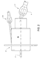
- FIG. 2 shows a master cylinder 15 according to the invention, in which a damper unit has been integrated into said cylinder.
- the master cylinder 15 is connected to a clutch pedal by means of an actuator arm 2.
- the master cylinder 2 comprises a housing 16 provided with a first fluid connector 17 connected to the hydraulic line 4.
- the housing is also provided with a second fluid connector 18 connected to a fluid reservoir (not shown) for maintaining a predetermined fluid level in the system.
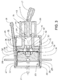
- Figure 3 shows a cross-section through the master cylinder 15 of Figure 2.
- the housing 16 comprises a first section 19, having a first diameter, and a second section 20, having a second, smaller diameter.
- the first and second sections 19, 20 are separated by a stepped section, which is preferably, but not necessarily, located in a radial plane at right angles to a central axis X of the housing.
- the relation between the first and second diameters can be selected depending on the length of stroke of the actuator arm 2, the desired pressure in the hydraulic line, and a number of other parameters.
- a piston 21 is slidably arranged in the housing 16 between a rest position, as shown in the figure, and an actuated position, as indicated by dash-dotted lines.
- the rest position of the piston 21 is limited by a stop in the form of a resilient spring clip 22 placed in a groove around the inner periphery of the first section 19 of the housing 16.
- a stop in the form of a resilient spring clip 22 placed in a groove around the inner periphery of the first section 19 of the housing 16.
- the end face of the housing 16 containing the first section 19 is shaped as an open cylindrical section.
- the piston 21 comprises a first hollow section 23, having a first diameter, and a second hollow section 24, having a second, smaller diameter.
- the first and second hollow sections 23, 24 are separated by a stepped section, which is preferably, but not necessarily, located in a radial plane at right angles to a central axis X of the housing.
- the first hollow section 23 is located adjacent the open end face of the housing 16 and provided with a cylindrical member 25 that can be slid into the first hollow section 23 and locked into position with a resilient spring clip 26 placed in a groove around the inner periphery of the first hollow section 23.
- the cylindrical member 25 is provided with attachment means 27 for the first actuator arm 2.
- said member 25 On its inner surface said member 25 is provided with a central recess 28 and an annular radial surface 29 adjacent its outer diameter.
- the annular surface 29 is provided with a groove containing a first seal 30.
- a stepped section 31 between the first and second hollow sections 23, 24 is provided with a corresponding groove containing a second seal 32.
- the seals 30, 32 preferably, but not necessarily, comprise O-rings made from a resilient material such as a rubber.
- a circular, flat membrane 33 is located between the annular section 29 of the cylindrical member 25 and the stepped section 31 of the piston.
- a cavity is created by the membrane 33 and the recess 28 in the cylindrical member 25, which cavity is sealed by said first seal 30.
- a further cavity is created by the membrane 33 and the second hollow section 24 in the piston. This further cavity is connected to the hydraulic line 4 at one end and is sealed by said second seal 32 at its opposite end, which seal 32 prevents hydraulic fluid from leaking past the membrane 33.
- the thickness and the free diameter of the membrane are selected with respect to the frequency and/or amplitude of the pressure pulses in the hydraulic fluid.
- the second hollow section 24 of the piston 21 comprises an inner and an outer section 34, 35.
- the inner section 34, adjacent the membrane 33, is provided with radial channels 36 connecting the hollow section 24 with the second fluid connector 18 that is connected to a fluid reservoir. This allows the volume of hydraulic fluid in the system to be maintained at a constant level, as fluid may be filled or drained through said radial channels 36 whenever the piston is in its rest position as shown in Figure 3.
- the piston is provided with multiple seals in grooves around the outer circumference of its first hollow section 23.
- a first seal 37 is located adjacent its outer open end, which seal maintains a seal between the second fluid connector 18 and the atmosphere when the piston is in its actuated position (dash-dotted lines in Fig.3).
- Further second and third seals 38, 39 are located in axially displaced positions on either side of the exits of said radial channels 36 connecting the hollow section 24 with the exit of the second fluid connector 18 when the piston is in its rest position, as described above.
- the inner section 34 of the second cavity is further provided with a support surface 40 that contacts a central portion of the membrane 33 when said membrane is at rest.
- the support surface 40 is connected to the inner wall of the second cavity by at least two radially extending sections 41 separated by fluid conducting openings 42.
- the membrane can be held flat, as shown in Figure 3, or in a pre-tensioned, concave shape into the first cavity.
- a spring (S) in the first recess 28 for spring loading the membrane 33 towards support surface 40.
- the spring element (S) can be any type of suitable spring, such as a coil compression spring (indicated in Fig. 3).
- the second cavity can also be arranged without a support surface for the membrane.
- the outer section 35 of the second cavity comprises a hollow cylindrical section that is slidably arranged along the outer surface of a tubular section 43 extending axially into the second section 20 of the housing 16 from the end wall of said housing.
- the tubular section 43 is provided with a seal 44 in a groove around its outer circumference. This seal 44 prevents hydraulic fluid from leaking out of the second cavity into a space 45 inside the housing surrounding the second hollow section 24 of the piston.
- This space 45 is taken up by the first hollow section 23 of the piston 21 when the clutch pedal 1 is actuated. Consequently the space 45 must be ventilated to the atmosphere in order to allow air to escape.
Landscapes
- Engineering & Computer Science (AREA)
- General Engineering & Computer Science (AREA)
- Mechanical Engineering (AREA)
- Physics & Mathematics (AREA)
- Fluid Mechanics (AREA)
- Transportation (AREA)
- Hydraulic Clutches, Magnetic Clutches, Fluid Clutches, And Fluid Joints (AREA)
Abstract
Description
- The present invention concerns a device to reduce vibrations in a hydraulic force transfer system. In particular, the invention relates to a device to suppress or reduce vibrations in hydraulic systems, such as a hydraulic line connecting a clutch pedal and a hydraulic clutch control unit in a vehicle.
- The conventional hydraulic clutch control has a master cylinder which can be activated via a clutch pedal and which is connected to a reservoir. The master cylinder is hydraulically connected via a pressure line with the slave cylinder, so that, when the clutch pedal is pressed, the pressure generated in the master cylinder is transferred via the fluid column in the pressure line to the slave cylinder. As a result the clutch release bearing receives an activation force from the slave cylinder in order to separate via a release mechanism the clutch pressure plate from the clutch flywheel and hence the combustion engine from the gearbox of the motor vehicle.
- In such hydraulic clutch controls, which can be regarded as quasi-stationary hydraulic force transfer systems in which there is no continuous flow of hydraulic fluid, the problem arises that vibrations from the combustion engine are transferred via the clutch plate, release mechanism, release bearing and fluid column in the pressure line between the slave cylinder and the master cylinder to the clutch pedal, so the clutch pedal vibrates perceptibly for the driver when he presses this down to release the clutch. The vibrations on the slave cylinder are transferred via the fluid column in the pressure line to the master cylinder as pressure pulses. This problem is particularly noticeable in high torque engines, such as diesel engines.
- One solution to this problem is shown in US 5 816 046 in which an additional oscillator is connected in the pressure line between the slave cylinder and the master cylinder. This additional oscillator has a housing, the base and/or cover of which is formed by a freely vibrating membrane whose edge is firmly clamped to the housing and which together with the housing delimits a chamber which can be connected via connections to the master cylinder and slave cylinder of the hydraulic clutch control so that the membrane is pressurized by the hydraulic line between the master cylinder and slave cylinder. In this state of the art, because of a low frequency exciter vibration on the slave cylinder a low frequency pressure pulse is transmitted via the fluid column between the master cylinder and slave cylinder, where this pressure pulse excites the additional oscillator provided in the fluid column and tuned accordingly such that the additional oscillator vibrates at its inherent frequency which is higher than the frequency of the low frequency pressure pulse, so that the additional oscillator in the fluid column induces a higher frequency pressure pulse which the vibration-susceptible system comprising the master cylinder and clutch pedal cannot follow.
- However, a problem with the above oscillator or damper arrangement is that it adds an additional component that must be located in the hydraulic line between the master cylinder and slave cylinder. In the engine compartment of a modern vehicle it is often difficult to find additional space, due the very compact packaging of the engine and its auxiliary components. The arrangement according to the invention solves both the problem relating to dampening of vibrations, as well as the problem of packaging the vibration dampening component without requiring additional space in the engine compartment.
- It is therefore an object of the present invention to provide a method and an apparatus that solves the above problems. This is achieved by device to reduce vibrations in a hydraulic force transfer system, according to claim 1, and a vehicle provided with such a device, according to
claim 14. - According to a first embodiment, the present invention relates to a device for reducing vibrations in a hydraulic force transfer system, which system comprises a master cylinder and a slave cylinder connected to the master cylinder via a hydraulic line. The hydraulic system may preferably, but not necessarily, be placed between a mechanical actuator, such as a foot pedal, and a clutch for an internal combustion engine. The device further comprises a membrane positioned in a housing in at least one of said cylinders, the membrane being attached to a piston in said housing, so that the membrane can be pressurized hydraulically by a fluid column in the hydraulic line between the master cylinder and slave cylinder.
- The said housing comprises a first cavity wherein the piston and the membrane delimit a first chamber that may be connected via a fluid connection to the master cylinder and via a further fluid connection to the slave cylinder. In addition, a second cavity in the piston and the membrane delimit a second chamber.
- The second cavity contains a member having an inner surface that delimits the second chamber and clamps the membrane around its peripheral edge. The membrane itself may have any suitable shape, but is preferably adapted to the respective cross-sectional shapes of the second cavity and the outer, peripheral contour of said member that is arranged to clamp the membrane in place. For manufacturing reasons, the cross-sectional shape of the second cavity and its co-operating member is preferably cylindrical. Consequently, the membrane may have a circular shape and can preferably, but not necessarily, be made of spring steel.
- The piston may be provided with a suitable means for retaining the said member in place. One such means may be a groove around the periphery of the internal surface of the second cavity to hold a fastening element, such as a resilient spring clip, for clamping the member against the membrane in the cavity. Alternative means may range from a permanent attachment, achieved by e.g. welding, to a spring loaded means. However, pressure pulses in the hydraulic line should preferably be dampened by the membrane and not by movement of the member clamping the membrane in place.
- According to a further embodiment the member itself may be replaced by a suitable spring element, such as a coil compression spring acting directly on the outer periphery of the membrane. The rear end of the said spring can be held in place by a circular resilient spring clip, as described above, or by means of an end closure means with an external threaded surface co-operating with an internal threaded surface in the second cavity.
- In order to prevent hydraulic fluid from leaking out of the first chamber, and partially to prevent vibrations from being transmitted into the piston, a sealing element may be provided. The second cavity of the piston may be provided an annular groove in a surface located substantially in a substantially annular surface created by a radial plane surrounding the opening of the first cavity concentrically. This groove may hold a first sealing element facing the membrane, which sealing element seals the first chamber against the environment.
- Similarly, the inner surface of the member placed in the second cavity of the piston may have an annular groove in a substantially radial plane in a part of its end surface surrounding the opening of the second cavity concentrically. This groove may hold a second sealing element facing the membrane, which sealing element seals the second chamber against the environment.
- The member, or end closure means, located in the second cavity of the piston may have an outer surface having connecting means for an actuator connected to the piston. This actuator may be a mechanical actuator, such as a foot pedal.
- The membrane may, at least in a rest state of the hydraulic force transfer system, be held against the direction of the hydraulic pressurization of the membrane by means of a spring element. The spring element may force the membrane against a support surface on at least one projection located in the first chamber. The spring element may be a coil compression spring.
- The face of the annular surface supporting the membrane and the support surface on the at least one projection can lie in one plane, so that the membrane loaded by a spring element in the rest state of the hydraulic force transfer system is advantageously held flat. However, depending on the requirements concerned it is also possible to provide an offset between the supporting surface on the projection and the face surface on the ring-cylindrical section in the axial direction of the device and/or to chamfer or make convex the supporting surface at the projection and/or the face surface at the ring-cylindrical section so that the membrane is held curved convex or concave under a defined pretension. The spring element used for locating the membrane can be a spring ring or a plate spring. However the use of a coil compression spring is preferred.
- As stated above the membrane can be made of spring steel. With a spring steel membrane with a ratio of diameter to thickness of the membrane preferably between 40 and 160, more preferably between 60 and 90, with the device according to the invention particularly good results can be achieved in the reduction of vibrations in a hydraulic clutch control.
- The piston containing the vibration damping membrane is preferably, but not necessarily, located in the master cylinder. Alternatively, such a piston may be located in the slave cylinder.
- The invention further relates to a motor vehicle provided with a device for reducing vibrations in a hydraulic force transfer system connecting an actuator device and a clutch in the vehicle.
- In the following text, the invention will be described in detail with reference to the attached drawings. These drawings are used for illustration only and do not in any way limit the scope of the invention. In the drawings:
- Figure 1
- shows a schematic drawing of a prior art system comprising a hydraulic line connecting a clutch pedal and a hydraulic clutch control unit in a vehicle;
- Figure 2
- shows a
master cylinder 15 according to the invention; - Figure 3
- shows a cross-section through the master cylinder of Figure 2.
- Figure 1 shows a system comprising a hydraulic line connecting a clutch pedal and a hydraulic clutch control unit in a vehicle, which line is provided with a damper unit. The figure shows a mechanical actuator in the form of a clutch pedal 1, or a first pivoted lever, acting on a
first actuator arm 2 that in turn actuates a piston (see Fig.3) in amaster cylinder 3. This causes an increased hydraulic pressure in a firsthydraulic line 4, which pressure actuates aslave cylinder 5 attached directly or adjacent to adriveline 6 by means of anattachment flange 7, or similar. Thedriveline 6 is driven by an engine, indicated by a crankshaft 8, connected to agearbox 9 that in turn is connected to the driving wheels (not shown) of the vehicle. Aclutch unit 10, such as a friction clutch, is provided between the crankshaft 8 and the gearbox in order to allow disengagement of the engine during a gear change. The pressure in thehydraulic line 4 acts on a piston (not shown) in theslave cylinder 5, causing a displacement of asecond actuator arm 11. Thesecond actuator arm 11 pivots asecond lever 12 that acts on athird actuator arm 13 to disengage theclutch unit 10. - Vibrations may be transmitted from the
clutch unit 10 through the linkage comprising thesecond lever 12 and thesecond actuator arm 11, causing pressure pulses in theslave cylinder 5, thehydraulic line 4 and themaster cylinder 3. Such pressure pulses will then be transmitted to the clutch pedal 1 and the foot of the driver of the vehicle. In order to eliminate such vibrations, the hydraulic line is provided with adamper unit 14 for dampening pressure pulses in thehydraulic line 4. - Figure 2 shows a
master cylinder 15 according to the invention, in which a damper unit has been integrated into said cylinder. As in Figure 1, themaster cylinder 15 is connected to a clutch pedal by means of anactuator arm 2. Furthermore, themaster cylinder 2 comprises ahousing 16 provided with afirst fluid connector 17 connected to thehydraulic line 4. The housing is also provided with asecond fluid connector 18 connected to a fluid reservoir (not shown) for maintaining a predetermined fluid level in the system. - Figure 3 shows a cross-section through the
master cylinder 15 of Figure 2. Thehousing 16 comprises afirst section 19, having a first diameter, and asecond section 20, having a second, smaller diameter. The first andsecond sections actuator arm 2, the desired pressure in the hydraulic line, and a number of other parameters. Apiston 21 is slidably arranged in thehousing 16 between a rest position, as shown in the figure, and an actuated position, as indicated by dash-dotted lines. The rest position of thepiston 21 is limited by a stop in the form of aresilient spring clip 22 placed in a groove around the inner periphery of thefirst section 19 of thehousing 16. In order to allow assembly of the master cylinder, the end face of thehousing 16 containing thefirst section 19 is shaped as an open cylindrical section. - Similar to the
housing 16, thepiston 21 comprises a firsthollow section 23, having a first diameter, and a secondhollow section 24, having a second, smaller diameter. The first and secondhollow sections hollow section 23 is located adjacent the open end face of thehousing 16 and provided with acylindrical member 25 that can be slid into the firsthollow section 23 and locked into position with aresilient spring clip 26 placed in a groove around the inner periphery of the firsthollow section 23. In its outer end surface, thecylindrical member 25 is provided with attachment means 27 for thefirst actuator arm 2. On its inner surface saidmember 25 is provided with acentral recess 28 and an annularradial surface 29 adjacent its outer diameter. Theannular surface 29 is provided with a groove containing afirst seal 30. Similarly, a steppedsection 31 between the first and secondhollow sections second seal 32. Theseals - A circular,
flat membrane 33 is located between theannular section 29 of thecylindrical member 25 and the steppedsection 31 of the piston. A cavity is created by themembrane 33 and therecess 28 in thecylindrical member 25, which cavity is sealed by saidfirst seal 30. A further cavity is created by themembrane 33 and the secondhollow section 24 in the piston. This further cavity is connected to thehydraulic line 4 at one end and is sealed by saidsecond seal 32 at its opposite end, which seal 32 prevents hydraulic fluid from leaking past themembrane 33. The thickness and the free diameter of the membrane are selected with respect to the frequency and/or amplitude of the pressure pulses in the hydraulic fluid. - The second
hollow section 24 of thepiston 21 comprises an inner and anouter section inner section 34, adjacent themembrane 33, is provided withradial channels 36 connecting thehollow section 24 with thesecond fluid connector 18 that is connected to a fluid reservoir. This allows the volume of hydraulic fluid in the system to be maintained at a constant level, as fluid may be filled or drained through saidradial channels 36 whenever the piston is in its rest position as shown in Figure 3. - The piston is provided with multiple seals in grooves around the outer circumference of its first
hollow section 23. Afirst seal 37 is located adjacent its outer open end, which seal maintains a seal between thesecond fluid connector 18 and the atmosphere when the piston is in its actuated position (dash-dotted lines in Fig.3). Further second andthird seals radial channels 36 connecting thehollow section 24 with the exit of thesecond fluid connector 18 when the piston is in its rest position, as described above. - The
inner section 34 of the second cavity is further provided with asupport surface 40 that contacts a central portion of themembrane 33 when said membrane is at rest. Thesupport surface 40 is connected to the inner wall of the second cavity by at least two radially extendingsections 41 separated byfluid conducting openings 42. Depending on the position of thesupport surface 40, the membrane can be held flat, as shown in Figure 3, or in a pre-tensioned, concave shape into the first cavity. - Alternatively, it is also possible to provide a spring (S) in the
first recess 28 for spring loading themembrane 33 towardssupport surface 40. In this way the membrane can be held flat or in a pre-tensioned, concave shape into the second cavity. The spring element (S) can be any type of suitable spring, such as a coil compression spring (indicated in Fig. 3). Depending on the dimensions of the membrane, the second cavity can also be arranged without a support surface for the membrane. - The
outer section 35 of the second cavity comprises a hollow cylindrical section that is slidably arranged along the outer surface of atubular section 43 extending axially into thesecond section 20 of thehousing 16 from the end wall of said housing. Thetubular section 43 is provided with aseal 44 in a groove around its outer circumference. Thisseal 44 prevents hydraulic fluid from leaking out of the second cavity into aspace 45 inside the housing surrounding the secondhollow section 24 of the piston. Thisspace 45 is taken up by the firsthollow section 23 of thepiston 21 when the clutch pedal 1 is actuated. Consequently thespace 45 must be ventilated to the atmosphere in order to allow air to escape. - The invention is not limited to the embodiments described above and may be varied freely within the scope of the appended claims.
Claims (14)
- A device for reducing vibrations in a hydraulic force transfer system, which system comprises a master cylinder (3) and a slave cylinder (5) connected to the master cylinder via a hydraulic line (4), characterized in that a membrane (33) is positioned in a housing (16) in at least one of said cylinders (3, 5), the membrane being attached to a piston (21) in said housing, so that the membrane can be pressurized hydraulically by a fluid column between the master cylinder and slave cylinder.
- A device according to claim 1, characterized in in that a cavity (24) in the piston (21) and the membrane (33) delimit a first chamber which can be connected via a connection to the master cylinder and via a further connection to the slave cylinder,
- A device according to claim 2, characterized in in that a member (25) placed in a second cavity (23) in the piston (21) and the membrane (33) delimit a second chamber.
- A device according to claim 3, characterized in in that the member (25) has an inner surface that has a recess (28) delimiting the second chamber and that clamps the membrane (33) around its peripheral edge.
- A device according to claim 4, characterized in in that the piston (21) has a groove around the periphery of the internal surface of the second cavity (23) to hold a fastening element (27) for clamping the member (25) in the cavity.
- A device according to claim 5, characterized in that the second cavity (23) of the piston has an annular groove in a substantially radial plane surrounding the opening of the first cavity concentrically to hold a sealing element (32) facing the membrane, which seals the first chamber against the environment.
- A device according to claim 5, characterized in that the inner surface of the member (25) has an annular groove in a substantially radial plane surrounding the opening of the second cavity concentrically to hold a sealing element (30) facing the membrane, which seals the second chamber against the environment.
- A device according to claim 5, characterized in in that the member has an outer surface having connecting means (27) for an actuator connected to the piston (21).
- A device according to claim 1, characterized in in that the membrane (33), at least in a rest state of the hydraulic force transfer system, is pressed by means of a spring element (S) against the direction of the hydraulic pressurization of the membrane against a support surface (40) in the first chamber.
- A device according to claim 1, characterized in in that the spring element is a coil compression spring.
- A device according to claim 1, characterized in in that the membrane is made of spring steel.
- A device according to any one of the above claims 1-11, characterized in in that the piston is located in the master cylinder.
- A device according to any one of the above claims 1-11, characterized in in that the piston is located in the slave cylinder.
- Motor vehicle provided with a device according to claim 1, to reduce vibrations in a hydraulic force transfer system connecting an actuator device and a clutch in the vehicle.
Priority Applications (2)
| Application Number | Priority Date | Filing Date | Title |
|---|---|---|---|
| EP04004333A EP1568907B1 (en) | 2004-02-26 | 2004-02-26 | Hydraulic force transfer system with a device for reducing vibrations and a vehicle provided with such a system |
| DE602004004629T DE602004004629T2 (en) | 2004-02-26 | 2004-02-26 | Hydraulic power transmission system having a vibration reducing device and a vehicle provided with such a system |
Applications Claiming Priority (1)
| Application Number | Priority Date | Filing Date | Title |
|---|---|---|---|
| EP04004333A EP1568907B1 (en) | 2004-02-26 | 2004-02-26 | Hydraulic force transfer system with a device for reducing vibrations and a vehicle provided with such a system |
Publications (2)
| Publication Number | Publication Date |
|---|---|
| EP1568907A1 true EP1568907A1 (en) | 2005-08-31 |
| EP1568907B1 EP1568907B1 (en) | 2007-02-07 |
Family
ID=34745901
Family Applications (1)
| Application Number | Title | Priority Date | Filing Date |
|---|---|---|---|
| EP04004333A Expired - Lifetime EP1568907B1 (en) | 2004-02-26 | 2004-02-26 | Hydraulic force transfer system with a device for reducing vibrations and a vehicle provided with such a system |
Country Status (2)
| Country | Link |
|---|---|
| EP (1) | EP1568907B1 (en) |
| DE (1) | DE602004004629T2 (en) |
Citations (6)
| Publication number | Priority date | Publication date | Assignee | Title |
|---|---|---|---|---|
| GB1592306A (en) * | 1976-11-03 | 1981-07-01 | Ferodo Sa | Hydraulic control cylinders |
| EP0591064A1 (en) * | 1992-10-01 | 1994-04-06 | Valeo | Electro hydraulic actuator |
| US5816046A (en) * | 1995-11-02 | 1998-10-06 | Fahrzeugtechnik Ebern Gmbh | Method of supressing vibrations of an actuation element of a hydraulic force transmission apparatus and auxiliary vibrator for carrying out the method |
| EP0894687A1 (en) * | 1994-03-16 | 1999-02-03 | Automotive Products France S.A. | Hydraulic actuating system |
| DE19920821C1 (en) * | 1999-05-06 | 2000-08-24 | Daimler Chrysler Ag | Hydraulic power transmission device, with membrane and carrier body forming auxiliary vibrator |
| US20020116924A1 (en) * | 1999-10-18 | 2002-08-29 | Luk Lamellen Und Kupplungsbau Gmbh | Master cylinder for use in power trains of motor vehicles |
-
2004
- 2004-02-26 DE DE602004004629T patent/DE602004004629T2/en not_active Expired - Lifetime
- 2004-02-26 EP EP04004333A patent/EP1568907B1/en not_active Expired - Lifetime
Patent Citations (6)
| Publication number | Priority date | Publication date | Assignee | Title |
|---|---|---|---|---|
| GB1592306A (en) * | 1976-11-03 | 1981-07-01 | Ferodo Sa | Hydraulic control cylinders |
| EP0591064A1 (en) * | 1992-10-01 | 1994-04-06 | Valeo | Electro hydraulic actuator |
| EP0894687A1 (en) * | 1994-03-16 | 1999-02-03 | Automotive Products France S.A. | Hydraulic actuating system |
| US5816046A (en) * | 1995-11-02 | 1998-10-06 | Fahrzeugtechnik Ebern Gmbh | Method of supressing vibrations of an actuation element of a hydraulic force transmission apparatus and auxiliary vibrator for carrying out the method |
| DE19920821C1 (en) * | 1999-05-06 | 2000-08-24 | Daimler Chrysler Ag | Hydraulic power transmission device, with membrane and carrier body forming auxiliary vibrator |
| US20020116924A1 (en) * | 1999-10-18 | 2002-08-29 | Luk Lamellen Und Kupplungsbau Gmbh | Master cylinder for use in power trains of motor vehicles |
Also Published As
| Publication number | Publication date |
|---|---|
| DE602004004629T2 (en) | 2007-11-22 |
| EP1568907B1 (en) | 2007-02-07 |
| DE602004004629D1 (en) | 2007-03-22 |
Similar Documents
| Publication | Publication Date | Title |
|---|---|---|
| US6325194B1 (en) | Hydraulic control clutch device equipped with a guide tube and method for producing such a tube | |
| US20110303315A1 (en) | Device for Reducing Pressure Pulsations | |
| US8636128B2 (en) | Slave cylinder for a vibration-damped hydraulic force transmission system, particularly a hydraulic clutch actuating system for motor vehicles | |
| US7107768B2 (en) | Hydraulic system | |
| CN101476604A (en) | Slave cylinder | |
| GB1562709A (en) | Clutch hydraulic actuation system | |
| US6745886B1 (en) | Motor vehicle clutch pedal vibration absorber | |
| US7578378B2 (en) | Valve arrangement for vibration decoupling, which can be connected between a master cylinder and a slave cylinder of a hydraulic force transmission system | |
| US7063200B2 (en) | Pulsation dampening apparatus and clutch master cylinder | |
| US6360863B1 (en) | Clutches | |
| US4924992A (en) | Anti-vibration mechanism for a clutch pedal | |
| EP1568907B1 (en) | Hydraulic force transfer system with a device for reducing vibrations and a vehicle provided with such a system | |
| US4416191A (en) | Vacuum booster device | |
| EP1083364A1 (en) | Flywheel | |
| JP3389823B2 (en) | Pulsation damping structure of pressure fluid piping | |
| US20080302618A1 (en) | Hydraulic Coupling For An Actuating System For Actuating A Motor Vehicle Clutch | |
| JP3051514B2 (en) | Anti-vibration device | |
| JP4016343B2 (en) | Anti-vibration actuator and active vibration isolator using the same | |
| JP2010210007A (en) | Hydraulic clutch release device | |
| WO2005108815A1 (en) | Hydraulic actuators | |
| JP2005282693A (en) | Active fluid-filled vibration isolator and manufacturing method of active fluid-filled vibration isolator | |
| KR100527774B1 (en) | Structure of clutch release bearing in automobile | |
| US20070261405A1 (en) | Hydraulic system | |
| JP3636730B2 (en) | Vibration isolator | |
| JP4793355B2 (en) | Arrangement structure of hydraulic equipment in clutch operating device |
Legal Events
| Date | Code | Title | Description |
|---|---|---|---|
| PUAI | Public reference made under article 153(3) epc to a published international application that has entered the european phase |
Free format text: ORIGINAL CODE: 0009012 |
|
| AK | Designated contracting states |
Kind code of ref document: A1 Designated state(s): AT BE BG CH CY CZ DE DK EE ES FI FR GB GR HU IE IT LI LU MC NL PT RO SE SI SK TR |
|
| AX | Request for extension of the european patent |
Extension state: AL LT LV MK |
|
| 17P | Request for examination filed |
Effective date: 20051005 |
|
| AKX | Designation fees paid |
Designated state(s): DE GB SE |
|
| RAP1 | Party data changed (applicant data changed or rights of an application transferred) |
Owner name: FORD GLOBAL TECHNOLOGIES, LLC. |
|
| GRAP | Despatch of communication of intention to grant a patent |
Free format text: ORIGINAL CODE: EPIDOSNIGR1 |
|
| RIN1 | Information on inventor provided before grant (corrected) |
Inventor name: VENNBERG, BJOERN |
|
| RTI1 | Title (correction) |
Free format text: HYDRAULIC FORCE TRANSFER SYSTEM WITH A DEVICE FOR REDUCING VIBRATIONS AND A VEHICLE PROVIDED WITH SUCH A SYSTEM |
|
| GRAS | Grant fee paid |
Free format text: ORIGINAL CODE: EPIDOSNIGR3 |
|
| GRAA | (expected) grant |
Free format text: ORIGINAL CODE: 0009210 |
|
| AK | Designated contracting states |
Kind code of ref document: B1 Designated state(s): DE GB SE |
|
| REG | Reference to a national code |
Ref country code: GB Ref legal event code: FG4D |
|
| REF | Corresponds to: |
Ref document number: 602004004629 Country of ref document: DE Date of ref document: 20070322 Kind code of ref document: P |
|
| REG | Reference to a national code |
Ref country code: SE Ref legal event code: TRGR |
|
| PLBE | No opposition filed within time limit |
Free format text: ORIGINAL CODE: 0009261 |
|
| STAA | Information on the status of an ep patent application or granted ep patent |
Free format text: STATUS: NO OPPOSITION FILED WITHIN TIME LIMIT |
|
| 26N | No opposition filed |
Effective date: 20071108 |
|
| REG | Reference to a national code |
Ref country code: GB Ref legal event code: 732E Free format text: REGISTERED BETWEEN 20111020 AND 20111025 |
|
| REG | Reference to a national code |
Ref country code: DE Ref legal event code: R082 Ref document number: 602004004629 Country of ref document: DE Representative=s name: ISARPATENT, DE |
|
| REG | Reference to a national code |
Ref country code: DE Ref legal event code: R081 Ref document number: 602004004629 Country of ref document: DE Owner name: VOLVO CAR CORPORATION, SE Free format text: FORMER OWNER: FORD GLOBAL TECHNOLOGIES, LLC, DEARBORN, MICH., US Effective date: 20120207 Ref country code: DE Ref legal event code: R082 Ref document number: 602004004629 Country of ref document: DE Representative=s name: ISARPATENT PATENTANWAELTE BEHNISCH, BARTH, CHA, DE Effective date: 20120207 |
|
| PGFP | Annual fee paid to national office [announced via postgrant information from national office to epo] |
Ref country code: GB Payment date: 20130226 Year of fee payment: 10 Ref country code: SE Payment date: 20130226 Year of fee payment: 10 Ref country code: DE Payment date: 20130221 Year of fee payment: 10 |
|
| REG | Reference to a national code |
Ref country code: DE Ref legal event code: R119 Ref document number: 602004004629 Country of ref document: DE |
|
| REG | Reference to a national code |
Ref country code: SE Ref legal event code: EUG |
|
| GBPC | Gb: european patent ceased through non-payment of renewal fee |
Effective date: 20140226 |
|
| PG25 | Lapsed in a contracting state [announced via postgrant information from national office to epo] |
Ref country code: SE Free format text: LAPSE BECAUSE OF NON-PAYMENT OF DUE FEES Effective date: 20140227 |
|
| REG | Reference to a national code |
Ref country code: DE Ref legal event code: R119 Ref document number: 602004004629 Country of ref document: DE Effective date: 20140902 |
|
| PG25 | Lapsed in a contracting state [announced via postgrant information from national office to epo] |
Ref country code: GB Free format text: LAPSE BECAUSE OF NON-PAYMENT OF DUE FEES Effective date: 20140226 Ref country code: DE Free format text: LAPSE BECAUSE OF NON-PAYMENT OF DUE FEES Effective date: 20140902 |