EP1568413A1 - Gas processing device and combustion efficiency improving device for engines - Google Patents
Gas processing device and combustion efficiency improving device for engines Download PDFInfo
- Publication number
- EP1568413A1 EP1568413A1 EP04255021A EP04255021A EP1568413A1 EP 1568413 A1 EP1568413 A1 EP 1568413A1 EP 04255021 A EP04255021 A EP 04255021A EP 04255021 A EP04255021 A EP 04255021A EP 1568413 A1 EP1568413 A1 EP 1568413A1
- Authority
- EP
- European Patent Office
- Prior art keywords
- processing device
- vibration generating
- gas
- electron
- electron vibration
- Prior art date
- Legal status (The legal status is an assumption and is not a legal conclusion. Google has not performed a legal analysis and makes no representation as to the accuracy of the status listed.)
- Withdrawn
Links
Images


Classifications
-
- B—PERFORMING OPERATIONS; TRANSPORTING
- B01—PHYSICAL OR CHEMICAL PROCESSES OR APPARATUS IN GENERAL
- B01J—CHEMICAL OR PHYSICAL PROCESSES, e.g. CATALYSIS OR COLLOID CHEMISTRY; THEIR RELEVANT APPARATUS
- B01J19/00—Chemical, physical or physico-chemical processes in general; Their relevant apparatus
- B01J19/08—Processes employing the direct application of electric or wave energy, or particle radiation; Apparatus therefor
- B01J19/12—Processes employing the direct application of electric or wave energy, or particle radiation; Apparatus therefor employing electromagnetic waves
- B01J19/122—Incoherent waves
- B01J19/128—Infrared light
-
- F—MECHANICAL ENGINEERING; LIGHTING; HEATING; WEAPONS; BLASTING
- F02—COMBUSTION ENGINES; HOT-GAS OR COMBUSTION-PRODUCT ENGINE PLANTS
- F02M—SUPPLYING COMBUSTION ENGINES IN GENERAL WITH COMBUSTIBLE MIXTURES OR CONSTITUENTS THEREOF
- F02M27/00—Apparatus for treating combustion-air, fuel, or fuel-air mixture, by catalysts, electric means, magnetism, rays, sound waves, or the like
- F02M27/04—Apparatus for treating combustion-air, fuel, or fuel-air mixture, by catalysts, electric means, magnetism, rays, sound waves, or the like by electric means, ionisation, polarisation or magnetism
-
- F—MECHANICAL ENGINEERING; LIGHTING; HEATING; WEAPONS; BLASTING
- F23—COMBUSTION APPARATUS; COMBUSTION PROCESSES
- F23C—METHODS OR APPARATUS FOR COMBUSTION USING FLUID FUEL OR SOLID FUEL SUSPENDED IN A CARRIER GAS OR AIR
- F23C99/00—Subject-matter not provided for in other groups of this subclass
- F23C99/001—Applying electric means or magnetism to combustion
-
- F—MECHANICAL ENGINEERING; LIGHTING; HEATING; WEAPONS; BLASTING
- F23—COMBUSTION APPARATUS; COMBUSTION PROCESSES
- F23D—BURNERS
- F23D14/00—Burners for combustion of a gas, e.g. of a gas stored under pressure as a liquid
- F23D14/46—Details
- F23D14/66—Preheating the combustion air or gas
-
- B—PERFORMING OPERATIONS; TRANSPORTING
- B01—PHYSICAL OR CHEMICAL PROCESSES OR APPARATUS IN GENERAL
- B01J—CHEMICAL OR PHYSICAL PROCESSES, e.g. CATALYSIS OR COLLOID CHEMISTRY; THEIR RELEVANT APPARATUS
- B01J2219/00—Chemical, physical or physico-chemical processes in general; Their relevant apparatus
- B01J2219/08—Processes employing the direct application of electric or wave energy, or particle radiation; Apparatus therefor
- B01J2219/0873—Materials to be treated
- B01J2219/0875—Gas
-
- C—CHEMISTRY; METALLURGY
- C02—TREATMENT OF WATER, WASTE WATER, SEWAGE, OR SLUDGE
- C02F—TREATMENT OF WATER, WASTE WATER, SEWAGE, OR SLUDGE
- C02F3/00—Biological treatment of water, waste water, or sewage
- C02F3/02—Aerobic processes
- C02F3/12—Activated sludge processes
-
- Y—GENERAL TAGGING OF NEW TECHNOLOGICAL DEVELOPMENTS; GENERAL TAGGING OF CROSS-SECTIONAL TECHNOLOGIES SPANNING OVER SEVERAL SECTIONS OF THE IPC; TECHNICAL SUBJECTS COVERED BY FORMER USPC CROSS-REFERENCE ART COLLECTIONS [XRACs] AND DIGESTS
- Y02—TECHNOLOGIES OR APPLICATIONS FOR MITIGATION OR ADAPTATION AGAINST CLIMATE CHANGE
- Y02E—REDUCTION OF GREENHOUSE GAS [GHG] EMISSIONS, RELATED TO ENERGY GENERATION, TRANSMISSION OR DISTRIBUTION
- Y02E20/00—Combustion technologies with mitigation potential
- Y02E20/34—Indirect CO2mitigation, i.e. by acting on non CO2directly related matters of the process, e.g. pre-heating or heat recovery
-
- Y—GENERAL TAGGING OF NEW TECHNOLOGICAL DEVELOPMENTS; GENERAL TAGGING OF CROSS-SECTIONAL TECHNOLOGIES SPANNING OVER SEVERAL SECTIONS OF THE IPC; TECHNICAL SUBJECTS COVERED BY FORMER USPC CROSS-REFERENCE ART COLLECTIONS [XRACs] AND DIGESTS
- Y02—TECHNOLOGIES OR APPLICATIONS FOR MITIGATION OR ADAPTATION AGAINST CLIMATE CHANGE
- Y02W—CLIMATE CHANGE MITIGATION TECHNOLOGIES RELATED TO WASTEWATER TREATMENT OR WASTE MANAGEMENT
- Y02W10/00—Technologies for wastewater treatment
- Y02W10/10—Biological treatment of water, waste water, or sewage
-
- Y—GENERAL TAGGING OF NEW TECHNOLOGICAL DEVELOPMENTS; GENERAL TAGGING OF CROSS-SECTIONAL TECHNOLOGIES SPANNING OVER SEVERAL SECTIONS OF THE IPC; TECHNICAL SUBJECTS COVERED BY FORMER USPC CROSS-REFERENCE ART COLLECTIONS [XRACs] AND DIGESTS
- Y02—TECHNOLOGIES OR APPLICATIONS FOR MITIGATION OR ADAPTATION AGAINST CLIMATE CHANGE
- Y02W—CLIMATE CHANGE MITIGATION TECHNOLOGIES RELATED TO WASTEWATER TREATMENT OR WASTE MANAGEMENT
- Y02W10/00—Technologies for wastewater treatment
- Y02W10/30—Wastewater or sewage treatment systems using renewable energies
- Y02W10/37—Wastewater or sewage treatment systems using renewable energies using solar energy
Definitions
- the present invention relates to a gas processing device for improving properties of the gas passing through a gas passage of an apparatus.
- the present invention also relates to a device for improving combustion efficiency for an engine of a vehicle and the like.
- the properties of water changes depending on the type and concentration of the salt dissolved in the water.
- the shape of electron clouds, or the state of water molecule electrons has a larger influence on the properties of water.
- electrostatic attraction of ions and charged particles dissolved in water becomes small.
- a neutralizing dispersion effect of potential differences occurs at the interface between, for example, water and metal. This causes ions and suspended substances in the water to be dispersed from the interface and prevents scales from being produced.
- the hydrotreater includes an electrode structure and an electron field generator.
- the electrode structure has a titanium anode rod arranged in the center of an external cylinder, which functions as a cathode.
- the electron field generator is positioned on the external cylinder. The properties of water are changed by a weak current that is applied to the water when passing between the two electrodes.
- This water processing technique is generally referred to as electron field processing and is applied in various fields.
- a water processing technique using a so-called magnet mixer has also been developed in the prior art.
- the magnet mixer water passes through a magnetic field while being rotated by the mixer.
- scale products contained in the water are electrochemically changed by an electric field generated based on Faraday's law. This weakens the electron bonding energy between a positive ion and a negative ion, which is the main cause of scale production. Further, scales that have already been produced are gradually pulverized and eliminated.
- hydrotreater and magnet mixer water must either pass through two electrodes or through a magnetic field.
- the hydrotreater and magnet mixer must be arranged in a pipe.
- the attachment and removal of the hydrotreater or magnet mixer is burdensome.
- the hydrotreater or magnet mixer When using the hydrotreater or the magnet mixer in an existing water processing facility, for example, the hydrotreater or magnet mixer must be installed in accordance with the facility.
- the above mentioned hydrotreater works under the following principles.
- wave motion is externally applied to an electron having a wave motion corresponding to its position in the molecule
- the wave motion of the electron is changed.
- the applicant of the present invention has proposed a water processing device disclosed in Japanese Patent No. 2882897.
- Each of the above mentioned water processing devices including that described in Japanese Patent No. 2882897 improves the properties of water passing through a water passage in an apparatus.
- these devices do not improve the properties of gas (e.g., oxygen or air) passing through the gas passage of the apparatus.
- gas e.g., oxygen or air
- these devices do not improve the fuel efficiency of an engine.
- a further object of the present invention is to improve the fuel efficiency of an engine.
- the present invention provides a gas processing device for processing gas passing through a gas passage of an apparatus.
- the gas processing device is provided with an electron vibration generating body including a main body having a large electric conductivity.
- the electron vibration generating body is vibrated when irradiated with light.
- the vibration of the electron vibration generating body is transmitted to the gas passage.
- the device includes an electron vibration generating main body having a resistivity being 0 to 200 ⁇ 10 -6 ⁇ cm at 20°C.
- the main body is vibrated when irradiated with light.
- a surface body is adhered to the main body.
- the surface body includes an infrared ray radiating substance for generating light in an infrared wavelength range of 10 -6 to 10 -4 m when the surface body is irradiated with light.
- An electric conductor is arranged between the main body and at least one of a fuel supply passage for supplying the engine with fuel and an air supply passage for supplying the engine with air.
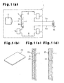
- FIG. 1(a), Fig. 2(a), Fig. 3(a) and Fig. 3(b) show an air processing device, which functions as a gas processing device, and applications thereof according to a first preferred embodiment of the present invention.
- an electron vibration generator 1 which functions as the air processing device, includes a light source 2, an electron vibration generating body 3, current limiters 4, and a power supply 5.
- the electron vibration generating body 3 and the current limiters 4 are connected in series to the power supply 5 by electric wires 6.
- Insulated connecting wires 6a, which extend from the electric wires 6, are connected to a connector 6b.
- the electron vibration generator 1 functions as an air processing device in this embodiment.
- the electron vibration generating body 3 includes a main body 3a, which is connected to the electric wire 6, and a surface body 3b, which is attached to the outer side of the main body 3a.
- the main body 3a is made of a substance having a large amount of free electrons and unpaired electrons. Further, the substance of the main body 3a has large electric conductivity. More specifically, the main body 3a is made of a metal, such as silver, copper, aluminum, gold, and steel, a compound of these metals, a metal alloy, or electric carbon. Further, the substance of the main body 3a preferably has a resistivity, which corresponds to the inverse of the electric conductivity, in a range of 0 to 200 x 10 -6 Q.cm at 20°C.
- the surface body 3b is made of a compound having a small ionic crystal radius, for example, a fluoride obtained by treating a substance with fluorine. More specifically, the surface body 3b is preferably made of a compound including positive ions having an ionic crystal radius in a range of 0.07 to 1.30 x 10 -10 m. The surface body 3b is actually made of a silver fluoride obtained by treating silver in fluorine gas or hydrogen fluoride and the like. The surface body 3b may be made of an iron oxide, a copper oxide, or a beryllium oxide.
- a resistor, a capacitor, a coil, or the like may be used as the current limiters 4.
- the capacitor and the coil are actually used as the current limiters 4.
- the power supply 5 may be a DC or AC power supply that is not affected by voltage or AC frequency.
- the power supply 5 is actually an AC power supply with a voltage of 12V and 210V.
- the electric wires 6 and the connecting wires 6a are electrically conductive. Copper wires are actually used as the electric wires 6 and the connecting wires 6a.
- the light source 2 efficiently radiates light with an infrared wavelength of 10 -6 to 10 -4 m.
- an infrared heater is used for the light source 2
- heat is easily generated and the life is short.
- an infrared light emitting diode, a semiconductor laser, and the like be used as the light source 2. This would reduce the size and power consumption and prolong the life of the light source 2.
- a white light emitting diode or a semiconductor laser emitting light in the wavelength of 300 ⁇ 10 -9 to 10 -6 m is actually used.
- the surface body 3b may be formed by applying an infrared ray radiating body, which is made of an infrared ray radiating substance that generates light having an infrared wavelength of 10 -6 to 10 -4 m, to the surface of the surface body 3b.
- the surface body 3b may be made by adhering a mixture of a powdered infrared ray radiating substance and an adhesive (e.g., transparent adhesive) to the surface of the surface body 3b or by mixing a powdered infrared ray radiating substance in the surface body 3b.
- the infrared ray radiating substance includes, for example, carbon (graphite), charcoal made from bamboo, wood, or coconut shells, or infrared ray generating ceramics.
- the crystal lattice of the main body 3a is vibrated. Specifically, when the light from the white light emitting diode or the semiconductor laser emitting light in the wavelength of 300 ⁇ 10 -9 to 10 -6 m is radiated to the surface of the surface body 3b, the infrared ray radiating substance in the surface body 3b radiates the light having the infrared wavelength of 10 -6 to 10 -4 m. Due to this light from the surface body 3b, the electron vibration generating body 3 vibrates efficiently. This vibrates the free electrons.
- the vibrations of the electron vibration generating body 3 becomes large when the light waveband is 10 -6 to 10 -4 m, increases when the light waveband is 1.5 ⁇ 10 -6 to 50 ⁇ 10 -6 m, and becomes significant when the light waveband is 3 ⁇ 10 -6 to 30 ⁇ 10 -6 m.
- the vibration of the electron vibration generating body 3 increases as the electric conductivity of the main body 3a in the electron vibration generating body 3 increases and the ionic crystal radius of the surface body 3b decreases.
- the vibrations of the free electrons are easily transmitted through the electric wires 6 and the connecting wires 6a.
- the surface body 3b is not necessarily required, and light may be radiated to the main body 3a.
- a magnet 7 (permanent magnet or electromagnet) may be attached or arranged close to the rear side of the main body 3a facing away from the outer side (surface body 3b) to which the light is radiated.
- the N-pole side of the magnet 7 is arranged facing towards the rear side of the main body 3a. The vibration generating efficiency in the electron vibration generating body 3 is increased by the magnet 7.
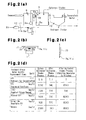
- sewage flows into a regulating tank 8.
- the sewage is then sent from the regulating tank 8 to an aeration tank 9 at a constant rate by a pump 8a.
- Active sludge is then sent from the aeration tank 9 and supplied to a sedimentation tank 10 in which the sludge is separated into sediment sludge and water.
- the sediment sludge is collected in the sedimentation tank 10 and the water is released from the sedimentation tank 10.
- An air supply duct 11 air supply passage or gas supply passage
- An air supply blower 12 blows gas, or air (oxygen), into the aeration tank 9 through the air supply duct 11.
- the electron vibration generator 1 is attached to the aeration tank 9 and the air supply duct 11.
- the connector 6b of the electron vibration generator 1 is connected to an outer wall 9a (electric conductor) of the aeration tank 9 and an outer wall 11a (electric conductor) of the air supply duct 11.
- the free electrons vibrate the crystal lattice in the electron vibration generating body 3.
- the vibration is transmitted from the connector 6b of the electron vibration generator 1 through the outer wall 9a of the aeration tank 9 and the outer wall 11a of the air supply duct 11. This vibrates the oxygen atoms of the air in an air chamber (air passage, gas passage) defined in the aeration tank 9 or in an air passage (gas passage) extending through the air supply duct 11.
- the vibrations of the free electrons match the resonance frequency of the oxygen atoms.
- the orbits of the oxygen atom electrons change.
- the oxygen is activated, the properties of the oxygen are changed, and aerobic microbes become active. This enhances sewage purification capability and improves the water quality of the sludge.
- the table shown in Fig. 2(d) shows the measurement results of the sediment sludge water quality before and after the active sludge processing in a state in which the electron vibration generator 1 is not used and in a state in which the electron vibration generator 1 is used.
- the results show that the purification capability of the sewage is enhanced and that the water quality of the sludge is improved in a preferable manner after the active sludge processing in a state in which the electron vibration generator 1 is attached to the aeration tank 9 and the air supply duct 11.
- the attachment of the electron vibration generator 1 is not limited to the outer wall 9a of the aeration tank 9 and the outer wall 11a of the air supply duct 11.
- the electron vibration generator 1 may be attached to another air passage portion in the aeration tank 9 and the air supply duct 11, as well as to aerobic processing tanks and air supply passages other than the aeration tank 9 and the air supply duct 11.
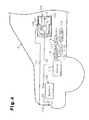
- the electron vibration generating body 3 of the electron vibration generator 100 may be connected to the fuel supply passage 115 and the air supply passage 117 of the engine 113 by the electric conductor without using the vehicle body 110.
- the present invention may also be used, besides in the engine 113 of the vehicle 102, to improve the combustion efficiency of various types of engines arranged in, for example, a factory.
Landscapes
- Engineering & Computer Science (AREA)
- Chemical & Material Sciences (AREA)
- General Engineering & Computer Science (AREA)
- Mechanical Engineering (AREA)
- Combustion & Propulsion (AREA)
- Chemical Kinetics & Catalysis (AREA)
- General Health & Medical Sciences (AREA)
- Organic Chemistry (AREA)
- Toxicology (AREA)
- Physics & Mathematics (AREA)
- Health & Medical Sciences (AREA)
- Electromagnetism (AREA)
- Physical Or Chemical Processes And Apparatus (AREA)
- Ignition Installations For Internal Combustion Engines (AREA)
Abstract
A gas processing device that improves the properties of
gas passing through a gas passage of an apparatus and is
easily installed on the gas passage of the apparatus. The
gas processing device is provided with an electron vibration
generating body including a main body having a large
electric conductivity. The electron vibration generating
body is vibrated when irradiated with light. An electric
conductor is arranged between the electron vibration
generating body and the gas passage for transmitting
vibration of the electron vibration generating body to the
gas passage.
Description
The present invention relates to a gas processing
device for improving properties of the gas passing through a
gas passage of an apparatus. The present invention also
relates to a device for improving combustion efficiency for
an engine of a vehicle and the like.
The properties of water changes depending on the type
and concentration of the salt dissolved in the water.
However, the shape of electron clouds, or the state of water
molecule electrons, has a larger influence on the properties
of water. Generally, in a state in which electrons have a
high energy level, which involves loss of potential energy
and decrease in entropy, electrostatic attraction of ions
and charged particles dissolved in water becomes small. As
a result, a neutralizing dispersion effect of potential
differences occurs at the interface between, for example,
water and metal. This causes ions and suspended substances
in the water to be dispersed from the interface and prevents
scales from being produced.
A hydrotreater using this scale prevention principle is
known in the art. The hydrotreater includes an electrode
structure and an electron field generator. The electrode
structure has a titanium anode rod arranged in the center of
an external cylinder, which functions as a cathode. The
electron field generator is positioned on the external
cylinder. The properties of water are changed by a weak
current that is applied to the water when passing between
the two electrodes. This water processing technique is
generally referred to as electron field processing and is
applied in various fields.
In addition to the hydrotreater, a water processing
technique using a so-called magnet mixer has also been
developed in the prior art. In the magnet mixer, water
passes through a magnetic field while being rotated by the
mixer. When passing through the magnetic field, scale
products contained in the water are electrochemically
changed by an electric field generated based on Faraday's
law. This weakens the electron bonding energy between a
positive ion and a negative ion, which is the main cause of
scale production. Further, scales that have already been
produced are gradually pulverized and eliminated.
In the aforementioned hydrotreater and magnet mixer,
water must either pass through two electrodes or through a
magnetic field. Thus, the hydrotreater and magnet mixer
must be arranged in a pipe. However, the attachment and
removal of the hydrotreater or magnet mixer is burdensome.
When using the hydrotreater or the magnet mixer in an
existing water processing facility, for example, the
hydrotreater or magnet mixer must be installed in accordance
with the facility.
The above mentioned hydrotreater works under the
following principles. When wave motion is externally
applied to an electron having a wave motion corresponding to
its position in the molecule, the wave motion of the
electron is changed. This changes the position of the
electron. That is, the change of wave motion of the
electron in the water can be considered as an amplification
of the wave motion, causing the electron to move outwards so
that the electron of the water shifts to a higher energy
level. This prevents scales from being produced, as
mentioned above.
Accordingly, the applicant of the present invention has
proposed a water processing device disclosed in Japanese
Patent No. 2882897.
Each of the above mentioned water processing devices
including that described in Japanese Patent No. 2882897
improves the properties of water passing through a water
passage in an apparatus. However, these devices do not
improve the properties of gas (e.g., oxygen or air) passing
through the gas passage of the apparatus. Furthermore,
these devices do not improve the fuel efficiency of an
engine.
It is an object of the present invention to provide an
effective gas processing device that improves the properties
of gas passing through a gas passage of an apparatus and is
easily installed on the gas passage of the apparatus. A
further object of the present invention is to improve the
fuel efficiency of an engine.
To achieve the above objects, the present invention
provides a gas processing device for processing gas passing
through a gas passage of an apparatus. The gas processing
device is provided with an electron vibration generating
body including a main body having a large electric
conductivity. The electron vibration generating body is
vibrated when irradiated with light. The vibration of the
electron vibration generating body is transmitted to the gas
passage.
Another aspect of the present invention is a combustion
efficiency improving device for an engine. The device
includes an electron vibration generating main body having a
resistivity being 0 to 200×10-6Ω·cm at 20°C. The main body
is vibrated when irradiated with light. A surface body is
adhered to the main body. The surface body includes an
infrared ray radiating substance for generating light in an
infrared wavelength range of 10-6 to 10-4 m when the surface
body is irradiated with light. An electric conductor is
arranged between the main body and at least one of a fuel
supply passage for supplying the engine with fuel and an air
supply passage for supplying the engine with air.
Other aspects and advantages of the invention will
become apparent from the following description, taken in
conjunction with the accompanying drawings, illustrating by
way of example the principles of the invention.
The invention, together with objects and advantages
thereof, may best be understood by reference to the
following description of the presently preferred embodiments
together with the accompanying drawings in which:
Fig. 1(a), Fig. 2(a), Fig. 3(a) and Fig. 3(b) show an
air processing device, which functions as a gas processing
device, and applications thereof according to a first
preferred embodiment of the present invention. As shown in
Fig. 1(a), an electron vibration generator 1, which
functions as the air processing device, includes a light
source 2, an electron vibration generating body 3, current
limiters 4, and a power supply 5. The electron vibration
generating body 3 and the current limiters 4 are connected
in series to the power supply 5 by electric wires 6.
Insulated connecting wires 6a, which extend from the
electric wires 6, are connected to a connector 6b. The
electron vibration generator 1 functions as an air
processing device in this embodiment.
The electron vibration generating body 3 includes a
main body 3a, which is connected to the electric wire 6, and
a surface body 3b, which is attached to the outer side of
the main body 3a. The main body 3a is made of a substance
having a large amount of free electrons and unpaired
electrons. Further, the substance of the main body 3a has
large electric conductivity. More specifically, the main
body 3a is made of a metal, such as silver, copper,
aluminum, gold, and steel, a compound of these metals, a
metal alloy, or electric carbon. Further, the substance of
the main body 3a preferably has a resistivity, which
corresponds to the inverse of the electric conductivity, in
a range of 0 to 200 x 10-6 Q.cm at 20°C. The surface body 3b
is made of a compound having a small ionic crystal radius,
for example, a fluoride obtained by treating a substance
with fluorine. More specifically, the surface body 3b is
preferably made of a compound including positive ions having
an ionic crystal radius in a range of 0.07 to 1.30 x 10⁻¹⁰ m.
The surface body 3b is actually made of a silver fluoride
obtained by treating silver in fluorine gas or hydrogen
fluoride and the like. The surface body 3b may be made of
an iron oxide, a copper oxide, or a beryllium oxide.
A resistor, a capacitor, a coil, or the like may be
used as the current limiters 4. The capacitor and the coil
are actually used as the current limiters 4. The power
supply 5 may be a DC or AC power supply that is not affected
by voltage or AC frequency. The power supply 5 is actually
an AC power supply with a voltage of 12V and 210V. The
electric wires 6 and the connecting wires 6a are
electrically conductive. Copper wires are actually used as
the electric wires 6 and the connecting wires 6a.
It is preferred that the light source 2 efficiently
radiates light with an infrared wavelength of 10-6 to 10-4 m.
When an infrared heater is used for the light source 2, heat
is easily generated and the life is short. Thus, it is
preferred that an infrared light emitting diode, a
semiconductor laser, and the like be used as the light
source 2. This would reduce the size and power consumption
and prolong the life of the light source 2. A white light
emitting diode or a semiconductor laser emitting light in
the wavelength of 300×10-9 to 10-6 m is actually used.
The surface body 3b may be formed by applying an
infrared ray radiating body, which is made of an infrared
ray radiating substance that generates light having an
infrared wavelength of 10-6 to 10-4 m, to the surface of the
surface body 3b. Alternatively, the surface body 3b may be
made by adhering a mixture of a powdered infrared ray
radiating substance and an adhesive (e.g., transparent
adhesive) to the surface of the surface body 3b or by mixing
a powdered infrared ray radiating substance in the surface
body 3b. The infrared ray radiating substance includes, for
example, carbon (graphite), charcoal made from bamboo, wood,
or coconut shells, or infrared ray generating ceramics.
When light from the light source 2 is radiated to the
surface of the surface body 3b in the electron vibration
generating body 3, the crystal lattice of the main body 3a
is vibrated. Specifically, when the light from the white
light emitting diode or the semiconductor laser emitting
light in the wavelength of 300×10-9 to 10-6 m is radiated to
the surface of the surface body 3b, the infrared ray
radiating substance in the surface body 3b radiates the
light having the infrared wavelength of 10-6 to 10-4 m. Due
to this light from the surface body 3b, the electron
vibration generating body 3 vibrates efficiently. This
vibrates the free electrons. The vibrations of the electron
vibration generating body 3 becomes large when the light
waveband is 10-6 to 10-4 m, increases when the light waveband
is 1.5×10⁻⁶ to 50×10-6 m, and becomes significant when the
light waveband is 3×10⁻⁶ to 30×10-6 m. In this case, the
vibration of the electron vibration generating body 3
increases as the electric conductivity of the main body 3a
in the electron vibration generating body 3 increases and
the ionic crystal radius of the surface body 3b decreases.
When the free electron enters the flow of current, the
vibrations of the free electrons are easily transmitted
through the electric wires 6 and the connecting wires 6a.
In the electron vibration generating body 3, the surface
body 3b is not necessarily required, and light may be
radiated to the main body 3a.
In the electron vibration generating body 3, a magnet 7
(permanent magnet or electromagnet) may be attached or
arranged close to the rear side of the main body 3a facing
away from the outer side (surface body 3b) to which the
light is radiated. In this case, the N-pole side of the
magnet 7 is arranged facing towards the rear side of the
main body 3a. The vibration generating efficiency in the
electron vibration generating body 3 is increased by the
magnet 7.
In a sewage processing apparatus (apparatus) shown in
Fig. 2(a), sewage flows into a regulating tank 8. The
sewage is then sent from the regulating tank 8 to an
aeration tank 9 at a constant rate by a pump 8a. Active
sludge is then sent from the aeration tank 9 and supplied to
a sedimentation tank 10 in which the sludge is separated
into sediment sludge and water. The sediment sludge is
collected in the sedimentation tank 10 and the water is
released from the sedimentation tank 10. An air supply duct
11 (air supply passage or gas supply passage) is connected
to the aeration tank 9 (processing tank). An air supply
blower 12 blows gas, or air (oxygen), into the aeration tank
9 through the air supply duct 11.
The electron vibration generator 1 is attached to the
aeration tank 9 and the air supply duct 11. The connector
6b of the electron vibration generator 1 is connected to an
outer wall 9a (electric conductor) of the aeration tank 9
and an outer wall 11a (electric conductor) of the air supply
duct 11. As mentioned above, when light is radiated on the
surface body 3b of the electron vibration generating body 3,
the free electrons vibrate the crystal lattice in the
electron vibration generating body 3. The vibration is
transmitted from the connector 6b of the electron vibration
generator 1 through the outer wall 9a of the aeration tank 9
and the outer wall 11a of the air supply duct 11. This
vibrates the oxygen atoms of the air in an air chamber (air
passage, gas passage) defined in the aeration tank 9 or in
an air passage (gas passage) extending through the air
supply duct 11.
In this case, the vibrations of the free electrons
match the resonance frequency of the oxygen atoms. This
vibrates the oxygen atoms. As a result, the orbits of the
oxygen atom electrons change. This changes the wave motions
of the electrons and shifts the oxygen atom electrons to
orbits of a higher energy level. Accordingly, the oxygen is
activated, the properties of the oxygen are changed, and
aerobic microbes become active. This enhances sewage
purification capability and improves the water quality of
the sludge.
The table shown in Fig. 2(d) shows the measurement
results of the sediment sludge water quality before and
after the active sludge processing in a state in which the
electron vibration generator 1 is not used and in a state in
which the electron vibration generator 1 is used. The
results show that the purification capability of the sewage
is enhanced and that the water quality of the sludge is
improved in a preferable manner after the active sludge
processing in a state in which the electron vibration
generator 1 is attached to the aeration tank 9 and the air
supply duct 11.
The attachment of the electron vibration generator 1 is
not limited to the outer wall 9a of the aeration tank 9 and
the outer wall 11a of the air supply duct 11. The electron
vibration generator 1 may be attached to another air passage
portion in the aeration tank 9 and the air supply duct 11,
as well as to aerobic processing tanks and air supply
passages other than the aeration tank 9 and the air supply
duct 11.
The above embodiment has the following advantages.
The electron vibration generating body 3 of the
electron vibration generator 100 may be connected to the
fuel supply passage 115 and the air supply passage 117 of
the engine 113 by the electric conductor without using the
vehicle body 110.
Although not shown, the present invention may also be
used, besides in the engine 113 of the vehicle 102, to
improve the combustion efficiency of various types of
engines arranged in, for example, a factory.
Claims (20)
- A gas processing device for processing gas passing through a gas passage of an apparatus,
the gas processing device being characterized by:an electron vibration generating body including a main body having a large electric conductivity, the electron vibration generating body being vibrated when irradiated with light, wherein the vibration of the electron vibration generating body is transmitted to the gas passage. - The gas processing device according to claim 1, characterized in that the main body has a resistivity inversely corresponding to the electric conductivity of the main body, said resistivity being 0 to 200×10-6Ω·cm at 20°C.
- The gas processing device according to claim 1 or 2, characterized in that the electron vibration generating body generates the vibration to shift the oxygen atom electrons to orbits of a higher energy level.
- The gas processing device according to any one of claims 1 to 3, characterized by:a light source for radiating light onto the electron vibration generating body; andan electric conductor arranged between the electron vibration generating body and the gas passage.
- The gas processing device according to claim 4, characterized in that the light source generates light in an infrared wavelength range of 10-6 to 10-4 m.
- The gas processing device according to any one of claims 1 to 5, characterized in that the electron vibration generating body includes a surface body adhered to the main body, the surface body including an infrared ray radiating substance for generating light in an infrared wavelength range of 10-6 to 10-4 m when the surface body is irradiated with light.
- The gas processing device according to claim 6, wherein the surface body is made of a compound having a ionic crystal radius in a range of 0.07 to 1.30 × 10⁻¹⁰ m.
- The gas processing device according to any one of claims 1 to 5, characterized in that the main body includes a surface layer having resistivity being 0 to 200×10-6Ω·cm at 20°C, the surface layer including an infrared ray radiating substance for generating light in an infrared wavelength range of 10-6 to 10-4 m when the surface layer is irradiated with light.
- The gas processing device according to claim 8, wherein the surface layer is made of a compound having a ionic crystal radius in a range of 0.07 to 1.30 × 10⁻¹⁰ m.
- The gas processing device according to any one of claims 5 to 9, characterized in that the apparatus is a sewage processing apparatus for supplying sewage to a processing tank and processing the sewage, the gas passage receiving the vibration of the electron vibration generating body is an air supply passage connected to the processing tank or an air chamber defined in the processing tank.
- The gas processing device according to any one of claims 5 to 9, characterized in that the apparatus is a combustion apparatus for mixing fuel and air for combustion, the gas passage receiving the vibration of the electron vibration generating body is at least one of an air supply passage for supplying the combustion apparatus with air and a fuel supply passage for supplying the combustion apparatus with fuel.
- The gas processing device according to any one of claims 1 to 11, characterized in that the apparatus is a combustion engine, the gas passage being at least one of an air supply passage for supplying the combustion apparatus with air and a fuel supply passage for supplying the combustion apparatus with fuel.
- The gas processing device according to claim 12, characterized by:wherein the electron vibration generator is attached to the socket, and the vibration of the electron vibration generator is transmitted via the vehicle body to at least one of the fuel supply passage and the air supply passage.an electron vibration generator including the electron vibration generating body and a light source for radiating light onto the electron vibration generating body; andan electric conductor arranged between the electron vibration generating body and at least one of the air supply passage and the fuel supply passage, the electric conductor including a vehicle body on which the engine is mounted, and the vehicle body including a cigarette lighter socket,
- The gas processing device according to claim 13, characterized in that the light source has a power source corresponding to a battery mounted on the vehicle body.
- The gas processing device according to claim 13 or 14, characterized by:a further electron vibration generating body attached to at least one of the fuel supply passage and the air supply passage, the further electron vibration generating body being vibrated by vibrations transmitted from the electron vibration generator via the vehicle body.
- The gas processing device according to any one of claims 1 to 15, characterized in that the electron vibration generating body is ring-shaped and fitted to an outer wall of the gas passage so as to extend around the gas passage.
- The gas processing device according to any one of claims 1 to 16, characterized in that the main body includes a front side that is irradiated with light and a rear side opposite to the front side, the gas processing device further comprising:a magnet attached to or arranged close to the main body on said rear side.
- The gas processing device according to claim 17, characterized in that the magnet has an N-pole side facing towards the rear side of the main body.
- The gas processing device according to claim 4 or 13, characterized in that the electron vibration generating body and a light source are arranged outside the gas passage, the electric conductor is connected to the electron vibration generating body, and the electric conductor transmits the vibration of the electron vibration generating body to the gas passage from outside the gas passage.
- A combustion efficiency improving device for an engine, the device being characterized by:an electron vibration generating main body having a resistivity being 0 to 200×10-6Ω·cm at 20°C, wherein the main body being vibrated when irradiated with light;a surface body adhered to the main body, the surface body including an infrared ray radiating substance for generating light in an infrared wavelength range of 10-6 to 10-4 m when the surface body is irradiated with light; andan electric conductor arranged between the main body and at least one of a fuel supply passage for supplying the engine with fuel and an air supply passage for supplying the engine with air.
Applications Claiming Priority (2)
| Application Number | Priority Date | Filing Date | Title |
|---|---|---|---|
| JP2004053934A JP2005240741A (en) | 2004-02-27 | 2004-02-27 | Combustion efficiency improving device for engine |
| JP2004053934 | 2004-02-27 |
Publications (1)
| Publication Number | Publication Date |
|---|---|
| EP1568413A1 true EP1568413A1 (en) | 2005-08-31 |
Family
ID=34747549
Family Applications (1)
| Application Number | Title | Priority Date | Filing Date |
|---|---|---|---|
| EP04255021A Withdrawn EP1568413A1 (en) | 2004-02-27 | 2004-08-20 | Gas processing device and combustion efficiency improving device for engines |
Country Status (3)
| Country | Link |
|---|---|
| US (1) | US20050207949A1 (en) |
| EP (1) | EP1568413A1 (en) |
| JP (1) | JP2005240741A (en) |
Cited By (1)
| Publication number | Priority date | Publication date | Assignee | Title |
|---|---|---|---|---|
| DE102011011819A1 (en) * | 2011-02-19 | 2012-08-23 | Mark Steyn | Device for increasing the amount of oxygen in the air mixture, supplied in internal combustion engine |
Families Citing this family (2)
| Publication number | Priority date | Publication date | Assignee | Title |
|---|---|---|---|---|
| WO2006088084A1 (en) * | 2005-02-16 | 2006-08-24 | Fire Up Ltd. | Fuel activation apparatus for methane gas |
| CN101865960A (en) * | 2010-06-04 | 2010-10-20 | 中兴通讯股份有限公司 | A method and device for monitoring equipment energy efficiency performance |
Citations (4)
| Publication number | Priority date | Publication date | Assignee | Title |
|---|---|---|---|---|
| US3941670A (en) * | 1970-11-12 | 1976-03-02 | Massachusetts Institute Of Technology | Method of altering biological and chemical activity of molecular species |
| US5138175A (en) * | 1989-09-14 | 1992-08-11 | Lehigh University | Lamp sheath assembly for optically-assisted gas decontamination process |
| JPH067742A (en) * | 1990-11-29 | 1994-01-18 | Keiichi Hasegawa | Electronicoscillation generating device and apparatus for treating water and water-containing substance by using it and electronic oscillation generating body |
| US5445800A (en) * | 1993-04-23 | 1995-08-29 | Mitsubishi Denki Kabushiki Kaisha | Reaction control method and apparatus using carbon soot molecules and organometallic complexes in excited state |
-
2004
- 2004-02-27 JP JP2004053934A patent/JP2005240741A/en not_active Withdrawn
- 2004-08-20 EP EP04255021A patent/EP1568413A1/en not_active Withdrawn
- 2004-08-23 US US10/924,362 patent/US20050207949A1/en not_active Abandoned
Patent Citations (4)
| Publication number | Priority date | Publication date | Assignee | Title |
|---|---|---|---|---|
| US3941670A (en) * | 1970-11-12 | 1976-03-02 | Massachusetts Institute Of Technology | Method of altering biological and chemical activity of molecular species |
| US5138175A (en) * | 1989-09-14 | 1992-08-11 | Lehigh University | Lamp sheath assembly for optically-assisted gas decontamination process |
| JPH067742A (en) * | 1990-11-29 | 1994-01-18 | Keiichi Hasegawa | Electronicoscillation generating device and apparatus for treating water and water-containing substance by using it and electronic oscillation generating body |
| US5445800A (en) * | 1993-04-23 | 1995-08-29 | Mitsubishi Denki Kabushiki Kaisha | Reaction control method and apparatus using carbon soot molecules and organometallic complexes in excited state |
Non-Patent Citations (1)
| Title |
|---|
| PATENT ABSTRACTS OF JAPAN vol. 018, no. 209 (C - 1190) 13 April 1994 (1994-04-13) * |
Cited By (3)
| Publication number | Priority date | Publication date | Assignee | Title |
|---|---|---|---|---|
| DE102011011819A1 (en) * | 2011-02-19 | 2012-08-23 | Mark Steyn | Device for increasing the amount of oxygen in the air mixture, supplied in internal combustion engine |
| WO2012110626A1 (en) | 2011-02-19 | 2012-08-23 | Steyn Mark | Device for increasing the oxygen quantity in an air mixture that is supplied into an internal combustion engine |
| DE202012012531U1 (en) | 2011-02-19 | 2013-03-22 | Mark Steyn | Device for increasing the amount of oxygen in the air mixture, supplied in internal combustion engine |
Also Published As
| Publication number | Publication date |
|---|---|
| JP2005240741A (en) | 2005-09-08 |
| US20050207949A1 (en) | 2005-09-22 |
Similar Documents
| Publication | Publication Date | Title |
|---|---|---|
| KR20240010054A (en) | cell, battery, charger, generator, fuel cell, hydrogen fuel cell | |
| US7387724B1 (en) | Fluid magnetizer | |
| Michl | Relationship of bonding to electronic spectra. Comments | |
| US20100000876A1 (en) | Caviation assisted sonochemical hydrogen production system | |
| EP1568413A1 (en) | Gas processing device and combustion efficiency improving device for engines | |
| JP6280691B2 (en) | Method for producing material activation material | |
| EP1649157B1 (en) | A method and equipment for reducing emission and fuel consumption in order to improve combustion in internal combustion engines | |
| EP1775053A3 (en) | Apparatus for generating a negatively charged ionic reducing gas | |
| US7410557B2 (en) | Hydrogen activating apparatus | |
| EP0781874A3 (en) | Apparatus for producing silicon single crystal | |
| JP2000263062A (en) | Apparatus for producing reformed water, method for producing reformed water, apparatus for producing emulsion fuel, and method for producing emulsion fuel | |
| TW555879B (en) | Plasma processing apparatus | |
| US20150239735A1 (en) | Apparatus and methods for generating hydrogen from water | |
| JP2004255239A (en) | Gas treatment apparatus | |
| JP2025093724A (en) | Hydrogen gas production method and production device | |
| CA2143482A1 (en) | Method of electrolyzing water and apparatus thereof | |
| CN1181296C (en) | Personal electric air feeder-regulator | |
| JP2882897B2 (en) | Water or water-containing treatment equipment | |
| EP0244842A3 (en) | Apparatus for forming thin film | |
| US20050178710A1 (en) | Substance activating method and device therefor | |
| JPH05329482A (en) | Ultrasonic underwater power generator and water conditioner by ultrasonic underwater power generation | |
| JP2013223853A (en) | Particle collection apparatus and particle detection apparatus provided with the same | |
| JP2006194230A (en) | Internal combustion engine and engine body using energy by electrolysis of water | |
| JP4637051B2 (en) | Water activation method and activation apparatus | |
| Tachibana et al. | Chemical Reactions Induced by Atmospheric Pressure Hydrogen Plasma |
Legal Events
| Date | Code | Title | Description |
|---|---|---|---|
| PUAI | Public reference made under article 153(3) epc to a published international application that has entered the european phase |
Free format text: ORIGINAL CODE: 0009012 |
|
| AK | Designated contracting states |
Kind code of ref document: A1 Designated state(s): AT BE BG CH CY CZ DE DK EE ES FI FR GB GR HU IE IT LI LU MC NL PL PT RO SE SI SK TR |
|
| AX | Request for extension of the european patent |
Extension state: AL HR LT LV MK |
|
| AKX | Designation fees paid | ||
| REG | Reference to a national code |
Ref country code: DE Ref legal event code: 8566 |
|
| STAA | Information on the status of an ep patent application or granted ep patent |
Free format text: STATUS: THE APPLICATION IS DEEMED TO BE WITHDRAWN |
|
| 18D | Application deemed to be withdrawn |
Effective date: 20060302 |