EP1566984B1 - A method of delivering multimedia associated with a voice link - Google Patents
A method of delivering multimedia associated with a voice link Download PDFInfo
- Publication number
- EP1566984B1 EP1566984B1 EP05250718A EP05250718A EP1566984B1 EP 1566984 B1 EP1566984 B1 EP 1566984B1 EP 05250718 A EP05250718 A EP 05250718A EP 05250718 A EP05250718 A EP 05250718A EP 1566984 B1 EP1566984 B1 EP 1566984B1
- Authority
- EP
- European Patent Office
- Prior art keywords
- party
- calling
- service
- multimedia content
- uniform resource
- Prior art date
- Legal status (The legal status is an assumption and is not a legal conclusion. Google has not performed a legal analysis and makes no representation as to the accuracy of the status listed.)
- Expired - Lifetime
Links
- 238000000034 method Methods 0.000 title claims description 42
- 230000000977 initiatory effect Effects 0.000 claims description 31
- 238000004891 communication Methods 0.000 claims description 26
- 230000004044 response Effects 0.000 claims description 19
- 230000005540 biological transmission Effects 0.000 claims description 13
- 238000012152 algorithmic method Methods 0.000 description 17
- 230000008569 process Effects 0.000 description 4
- 238000012986 modification Methods 0.000 description 3
- 230000004048 modification Effects 0.000 description 3
- 238000012545 processing Methods 0.000 description 3
- 230000003319 supportive effect Effects 0.000 description 3
- 238000013459 approach Methods 0.000 description 2
- 230000008901 benefit Effects 0.000 description 2
- 230000001413 cellular effect Effects 0.000 description 2
- 230000000994 depressogenic effect Effects 0.000 description 2
- 238000001228 spectrum Methods 0.000 description 2
- 239000000969 carrier Substances 0.000 description 1
- 230000010267 cellular communication Effects 0.000 description 1
- 230000001419 dependent effect Effects 0.000 description 1
- 238000005516 engineering process Methods 0.000 description 1
- 230000007717 exclusion Effects 0.000 description 1
- 230000002452 interceptive effect Effects 0.000 description 1
- 230000001788 irregular Effects 0.000 description 1
- 238000013507 mapping Methods 0.000 description 1
- 239000000463 material Substances 0.000 description 1
- 230000011664 signaling Effects 0.000 description 1
- 230000007480 spreading Effects 0.000 description 1
- 238000012876 topography Methods 0.000 description 1
- 238000012546 transfer Methods 0.000 description 1
Images



Classifications
-
- H—ELECTRICITY
- H05—ELECTRIC TECHNIQUES NOT OTHERWISE PROVIDED FOR
- H05B—ELECTRIC HEATING; ELECTRIC LIGHT SOURCES NOT OTHERWISE PROVIDED FOR; CIRCUIT ARRANGEMENTS FOR ELECTRIC LIGHT SOURCES, IN GENERAL
- H05B1/00—Details of electric heating devices
- H05B1/02—Automatic switching arrangements specially adapted to apparatus ; Control of heating devices
- H05B1/0202—Switches
-
- H—ELECTRICITY
- H04—ELECTRIC COMMUNICATION TECHNIQUE
- H04W—WIRELESS COMMUNICATION NETWORKS
- H04W4/00—Services specially adapted for wireless communication networks; Facilities therefor
- H04W4/20—Services signaling; Auxiliary data signalling, i.e. transmitting data via a non-traffic channel
-
- G—PHYSICS
- G01—MEASURING; TESTING
- G01R—MEASURING ELECTRIC VARIABLES; MEASURING MAGNETIC VARIABLES
- G01R15/00—Details of measuring arrangements of the types provided for in groups G01R17/00 - G01R29/00, G01R33/00 - G01R33/26 or G01R35/00
- G01R15/14—Adaptations providing voltage or current isolation, e.g. for high-voltage or high-current networks
- G01R15/18—Adaptations providing voltage or current isolation, e.g. for high-voltage or high-current networks using inductive devices, e.g. transformers
-
- H—ELECTRICITY
- H04—ELECTRIC COMMUNICATION TECHNIQUE
- H04M—TELEPHONIC COMMUNICATION
- H04M3/00—Automatic or semi-automatic exchanges
- H04M3/42—Systems providing special services or facilities to subscribers
- H04M3/42382—Text-based messaging services in telephone networks such as PSTN/ISDN, e.g. User-to-User Signalling or Short Message Service for fixed networks
-
- H—ELECTRICITY
- H04—ELECTRIC COMMUNICATION TECHNIQUE
- H04M—TELEPHONIC COMMUNICATION
- H04M7/00—Arrangements for interconnection between switching centres
- H04M7/0024—Services and arrangements where telephone services are combined with data services
-
- H—ELECTRICITY
- H04—ELECTRIC COMMUNICATION TECHNIQUE
- H04L—TRANSMISSION OF DIGITAL INFORMATION, e.g. TELEGRAPHIC COMMUNICATION
- H04L65/00—Network arrangements, protocols or services for supporting real-time applications in data packet communication
- H04L65/1066—Session management
- H04L65/1101—Session protocols
- H04L65/1104—Session initiation protocol [SIP]
-
- H—ELECTRICITY
- H04—ELECTRIC COMMUNICATION TECHNIQUE
- H04M—TELEPHONIC COMMUNICATION
- H04M2201/00—Electronic components, circuits, software, systems or apparatus used in telephone systems
- H04M2201/50—Telephonic communication in combination with video communication
-
- H—ELECTRICITY
- H04—ELECTRIC COMMUNICATION TECHNIQUE
- H04M—TELEPHONIC COMMUNICATION
- H04M2203/00—Aspects of automatic or semi-automatic exchanges
- H04M2203/65—Aspects of automatic or semi-automatic exchanges related to applications where calls are combined with other types of communication
- H04M2203/654—Pre, in or post-call message
-
- H—ELECTRICITY
- H04—ELECTRIC COMMUNICATION TECHNIQUE
- H04M—TELEPHONIC COMMUNICATION
- H04M3/00—Automatic or semi-automatic exchanges
- H04M3/42—Systems providing special services or facilities to subscribers
- H04M3/487—Arrangements for providing information services, e.g. recorded voice services or time announcements
-
- H—ELECTRICITY
- H04—ELECTRIC COMMUNICATION TECHNIQUE
- H04M—TELEPHONIC COMMUNICATION
- H04M3/00—Automatic or semi-automatic exchanges
- H04M3/42—Systems providing special services or facilities to subscribers
- H04M3/487—Arrangements for providing information services, e.g. recorded voice services or time announcements
- H04M3/4872—Non-interactive information services
- H04M3/4878—Advertisement messages
-
- H—ELECTRICITY
- H05—ELECTRIC TECHNIQUES NOT OTHERWISE PROVIDED FOR
- H05B—ELECTRIC HEATING; ELECTRIC LIGHT SOURCES NOT OTHERWISE PROVIDED FOR; CIRCUIT ARRANGEMENTS FOR ELECTRIC LIGHT SOURCES, IN GENERAL
- H05B2203/00—Aspects relating to Ohmic resistive heating covered by group H05B3/00
- H05B2203/035—Electrical circuits used in resistive heating apparatus
Definitions
- the present invention relates to telecommunications, and more particularly, to wireless communications.
- Wireless communications systems provide wireless service to a number of wireless or mobile units situated within a geographic region.
- the geographic region supported by a wireless communications system is divided into spatially distinct areas commonly referred to as "cells.”
- Each cell ideally, may be represented by a hexagon in a honeycomb pattern. In practice, however, each cell may have an irregular shape, depending on various factors including the topography of the terrain surrounding the cell.
- each cell is further broken into two or more sectors. Each cell is commonly divided into three sectors, each having a range of about 120 degrees, for example.
- a conventional cellular system comprises a number of cell sites or base stations geographically distributed to support the transmission and reception of communication signals to and from the wireless or mobile units. Each cell site handles voice communications within a cell. Moreover, the overall coverage area for the cellular system may be defined by the union of cells for all of the cell sites, where the coverage areas for nearby cell sites overlap to ensure, where possible, contiguous communication coverage within the outer boundaries of the system's coverage area.
- Each base station comprises at least one radio and at least one antenna for communicating with the wireless units in that cell. Moreover, each base station also comprises transmission equipment for communicating with a Mobile Switching Center (“MSC”).
- MSC Mobile Switching Center
- a mobile switching center is responsible for, among other things, establishing and maintaining calls between the wireless units, between a wireless unit and a wireline unit through a public switched telephone network (“PSTN”), as well as between a wireless unit and a packet data network (“PDN”), such as the Internet.
- PSTN public switched telephone network
- PDN packet data network
- a base station controller administers the radio resources for one or more base stations and relays this information to the MSC.
- a wireless unit When active, a wireless unit receives signals from at least one base station over a forward link or downlink and transmits signals to at least one base station over a reverse link or uplink.
- TDMA time-division multiple access
- OFDMA orthogonal-frequency division multiple access
- CDMA code-division multiple access
- TDMA Time Division Multiple Access
- the radio spectrum is divided into time slots.
- Each time slot is designed to allow only one user to transmit and/or receive in this scheme.
- TDMA may require precise timing between the transmitter and receiver so that each user may transmit their information during their allocated time.
- each wireless channel is distinguished by a distinct channelization code (e.g., spreading code, spread spectrum code or Walsh code).
- Each distinct channelization code is used to encode different information streams. These information streams may then be modulated at one or more different carrier frequencies for simultaneous transmission.
- a receiver may recover a particular stream from a received signal using the appropriate channelization code to decode the received signal.
- a carrier signal may be defined by a number (e.g., 1024) of sub-carriers or tones transmitted using a set of mathematically timed orthogonal continuous waveforms.
- Each wireless channel may be distinguished by a distinct channelization tone.
- continuous waveforms the transmission and/or reception of the tones may be achieved because their orthogonality prevents them from interfering with one another.
- CS circuit- switched
- PS packet-switched
- WSPs wireless service providers
- WSPs One area for revenue generation that has not been fully explored by WSPs involves the close collaboration of voice, carried over a CS type network, in combination with data/multimedia, carried over a PS type network.
- CS and PS networks are relatively independent of each other from the end-user and services points of view.
- services and/or applications offered by WSPs use the strengths of one type network to the exclusion of the other. Consequently, end-users may not the benefits or enhanced user experience offered by the simultaneous use of both network types. WSPs have not, therefore, derived additional revenue from any enhanced services from the simultaneous use of both network types.
- WSPs' networks have not been utilized to their fullest potential.
- Patent Cooperation Treaty (PCT) Patent Application No. WO 01/06679 relates to a method and system for providing customized information to a calling subscriber during a call setup process, that is, while the subscriber is waiting for a called party's answer after making a call setup request.
- the application provides an information provision apparatus, interconnecting with an exchange, for providing the realtime customized information to an originating subscriber.
- the apparatus capable of connecting the Internee is coupled with a short message service center through a predetermined closed network.
- the mobile subscriber can make a new subscription for the information provision service on the Internet.
- the subscription state is stored in a homo location register (HLR).
- HLR homo location register
- the exchange interconnected with the apparatus executes the service to the originating subscriber based on the subscription information of the HLR.
- the service is continued till a called party answers to the call.
- the apparatus supplies access information with which the originating subscriber may obtain more detailed information additionally.
- the access information including a telephone number, URL, etc. is provided to the originating subscriber through the short message service center.
- the customized information which the subscriber receives can be selected by the subscriber on the Internet, or alternated according to the service subscriber's information or the subscriber's location information automatically.
- Patent Cooperation Treaty (PCT) Patent Application No. WO 02/089448 relates to a method for processing a request from a first terminal to establish a communication session between the first terminal and a second terminal, the first terminal and the second terminal being operable to communicate via a telecommunication network, the method comprising: receiving at the telecommunication network a request from the first terminal to establish a communication session with the second terminal; determining whether the second terminal is available to support the communication session; and if the second terminal is determined not to be available to support the communication session, transmitting to the first terminal the address of a data set corresponding to the second terminal.
- United States Patent No. 6,222,826 relates to a method and apparatus for establishing multimedia calls over an intelligent telecommunications network in which the calls are requested through an internetwork of client computers and server computers and the internetwork of client computers and server computers is further connected to the intelligent telecommunications network.
- the method involves: 1) a caller generating a request for a call utilizing the internetwork to initiate the request; 2) delivering multimedia and/or audiovisual presentations(s) to the caller via the internetwork and/or public switched telephone network (PSTN); and 3) completing a circuit switched telephone call between the caller and a destination user subsequent to the delivery of the presentations(s) wherein the call is placed from within the intelligent network itself.
- PSTN public switched telephone network
- a method is needed to support the service to both network types.
- the present invention provides a method of providing service to multiple network types by a wireless unit in the context of person-to-person voice calling. More particularly, the present invention provides a method for cooperatively providing voice service(s), carried over a circuit-switched ("CS") type network, with multimedia service(s), carried over a packet-switched (“PS”) type network to a wireless unit.
- a multimedia service(s) includes the delivery of multimedia content, such as a video clip(s), a web page(s), as well as data services, such as the delivery of a non-multimedia content type data file(s), for example.
- providing collaboration of voice service(s) with multimedia service(s), as stated herein includes communication between a calling-from-party and a calling-to-party, one or both of which may be directed from a wireless or wireline unit.
- a method of the present invention involves the communication between a calling-from-party and a calling-to-party.
- the method includes the step of receiving an initiation signal from the calling-from-party for identifying the calling-to-party.
- the method selects multimedia content to be transmitted to the calling-from-party.
- a voice link may then be established to the calling-to-party in response to the initiation signal from the calling-from-party.
- the initiation signal may be bridged to establish a voice link between the calling-from-party the calling-to-party. This bridging may rely on the previously established voice link.
- a method of the present invention involves the communication between a calling-from-party and a calling-to-party.
- the method includes the step of transmitting a uniform resource locator to the calling-from-party in response to an initiation signal transmitted from the calling-from-party.
- the uniform resource locator may be transmitted over a data link (e.g., data session).
- the uniform resource locator identifies a location where multimedia content may be accessed by the calling-from-party if the calling-to-party is a service subscriber according to a database of service subscribers. Subsequently, another data link (e.g., data session) may be established for the downlink of the multimedia content.
- a voice link may then be established to the calling-to-party in response to the initiation signal from the calling-from-party. Thereafter, the initiation signal may be bridged to establish a voice link between the calling-from-party and the calling-to-party. This bridging may rely on the previously established voice link.
- the established data links e.g., data sessions
- a flow chart depicting one embodiment of the present invention is illustrated.
- an algorithmic method 100 is shown for use with multiple network types. More particularly, method 100 depicts a sequence of steps in providing a collaboration of a voice service(s), carried over a circuit-switched (“CS") type network, with multimedia service(s), carried over a packet-switched (“PS”) type network.
- a multimedia service(s) includes the delivery of multimedia content, such as a video clip(s), a web page(s), as well as data services, such as the delivery of a non-multimedia content type data file(s), for example.
- providing collaboration of voice service(s) with multimedia service(s), as stated herein includes communication between a calling-from-party and a calling-to-party, one or both of which may be directed from a wireless or wireline unit.
- Algorithmic method 100 initially provides for the step of transmitting an initiation signal from a calling-from-party (step 110).
- This initiation signal is received by a communication network infrastructure element, such as a service control point/service node (e.g., server), for example.
- the step of transmitting the initiation signal may include entering the telephone number of the calling-to-party into the temporary memory of the calling-from-party's wireless or wireline unit.
- a corresponding send button or the like on the calling-from-party's wireless or wireline unit may be depressed so as to commence the sequence of steps in formulating a telephonic connection between the calling-from- and calling-to- parties. Consequently, the initiation signal identifies the calling-to-party.
- the service control point/service node may determine if the calling-to-party is a subscriber to the collaboration of voice and multimedia services (step 120). This step of determining may include the step of looking up the telephone number of the calling-to-party in a database of service subscribers. If the calling-to-party is determined to be a service subscriber, algorithmic method 100 proceeds as depicted in the flow chart of FIG. 1. However, if the telephone number is not found within a database, the remainder of algorithmic method 100 may be terminated. In this case, the initiation signal triggers either a voice link or data link (e.g., sessions) connecting the calling-from-party with the calling-to-party.
- a voice link or data link e.g., sessions
- algorithmic method 100 may transmit multimedia content to the calling-from-party (step 130).
- the calling-to-party's identity e.g., telephone number
- This multimedia content may, for example, include commercial matter, such as advertising and/or marketing material, or general information, for example, selected in response to the calling-to-party's identity.
- the step of transmitting multimedia content may include establishing a data link (e.g., data session) in the event the calling-to-party is found to be a service subscriber.
- This established data link e.g., data session
- the service control point/service node e.g., server
- the established data link e.g., data session
- PS packet switched
- algorithmic method 100 establishes an intermediate voice link to the calling-to-party (step 140).
- the intermediate voice link may be established by the service control point/service node supporting the transmissions of multimedia content to the calling-from-party.
- the intermediate voice link may rely on a circuit switched ("CS") type network.
- the service control point/service node may thereafter bridge the initiation signal and the intermediate voice link (step 150). Consequently, a voice call between the calling-from-party and the calling-to-party, as initiated at the onset of algorithmic method 100, may be established and completed. It should be noted that this step of bridging may be performed after the transmission of multimedia content is concluded, though it is may also occur prior thereto.
- Method 100 also depicts a sequence of steps in providing a collaboration of voice service(s), carried over a circuit-switched (“CS") type network, with multimedia service(s), carried over a packet-switched (“PS”) type network.
- CS circuit-switched
- PS packet-switched
- Algorithmic method 200 initially provides for the step of transmitting an initiation signal from a calling-from-party (step 110).
- This initiation signal is received by a communication network infrastructure element, such as a service control point/service node (e.g., server), for example.
- the step of transmitting the initiation signal may include entering the telephone number of the calling-to-party into the temporary memory of the calling-from-party's wireless or wireline unit.
- a corresponding send button or the like on the calling-from-party's wireless or wireline unit may be depressed so as to commence the sequence of steps in formulating a telephonic connection between the calling-from- and calling-to- parties. Consequently, the initiation signal identifies the calling-to-party.
- the service control point/service node may determine if the calling-to-party is a subscriber to the collaboration of voice and multimedia services (step 220). This step of determining may include the step of looking up the telephone number of the calling-to-party in a database of service subscribers. If the calling-to-party is determined to be a service subscriber, algorithmic method 200 proceeds as depicted in the flow chart of FIG. 2. In the alternative, should the telephone number of the calling-to-party not be found within a database, the offering of collaborative voice and multimedia services the remainder of algorithmic method 200 may be terminated. In this case, the initiation signal triggers either a voice link or data link (e.g., session) connecting the calling-from-party with the calling-to-party.
- a voice link or data link e.g., session
- algorithmic method 200 establishes a data link (e.g., data session) to the calling-from-party (step 230).
- a uniform resource locator (“URL") may be selected in response to affirming if calling-to-party is a service subscriber.
- This URL may identify the location where multimedia content may be received by the calling-from-party over a downlink. It should be noted that the URL might be designated in advance by the calling-to-party, as part of the service subscription.
- algorithmic method 200 establishes another data link (e.g., data session) (step 240).
- this subsequent data link e.g., data session
- this additional data link is intended in the scenario where the multimedia content cannot be transmitted over the same data link (e.g., data session) in which the URL is communicated. This may also arise, for example, if the multimedia content is stored in a network element physically separated from the network element storing the URL.
- algorithmic method 200 calls for establishing an intermediate voice link (step 250).
- This intermediate voice link is established to the calling-to-party.
- the intermediate voice link may be established by the service control point/service node supporting the transmissions of multimedia content to the calling-from-party.
- the intermediate voice link may rely on a circuit switched ("CS") type network.
- the aforementioned data links should be terminated in a logical sequence (step 260).
- the established data link e.g., data session
- the established data link for the transmission of the URL might be terminated in response to the establishing the intermediate voice link.
- the established data link e.g., data session
- the established data link for the transmission of the multimedia content may also be terminated.
- the service control point/service node may thereafter bridge the initiation signal and the intermediate voice link (step 270). Consequently, a voice call between the calling-from-party and the calling-to-party, as initiated at the onset of algorithmic method 200, may be established and completed. It should be noted that this step of bridging may be performed after the transmission of multimedia content is concluded, though it is may also occur prior thereto.
- the present invention may provide a framework for the creation of enhanced services utilizing simultaneous CS voice and PS data capabilities of the network.
- the present invention may be based on widely used telecommunication signaling technologies and Internet standards, such as a session initiation protocol ("SIP"), for example.
- SIP session initiation protocol
- the present invention may combine both in a manner that may minimize the impact to the existing network infrastructure.
- a call flow 300 supportive of the present invention is illustrated.
- a wireless circuit switched (“CS") network 310 and a wireless packet switched (“PS") network 320 may be included as part of a network configuration.
- the network configuration may also include a service control point/service node 330 (e.g., eMRS, which acts as both a SCP and SN) with a user information database formed therein, a first wireless unit supportive of simultaneous CS voice and PS data 340 (e.g., class A terminal), and a video server 360 to support call flow 300.
- a service control point/service node 330 e.g., eMRS, which acts as both a SCP and SN
- a first wireless unit supportive of simultaneous CS voice and PS data 340 e.g., class A terminal
- call flow 300 may process the call control when first wireless unit 340 initiates a voice call toward a called (wireline or wireless) receiving unit 370.
- call flow 300 may process call control if it receives other triggers from the network - e.g., answer and/or disconnect.
- the application of simultaneous CS voice and PS data may enable the performance of the appropriate tasks for the service, including, for example, initiating and/or terminating a data session.
- First wireless unit 340 may have a client application(s) for handling the needs of a service, such as a session initiation protocol ("SIP") stack to process the message, establishing a multimedia session, and for streaming video and/or audio, controls, for example.
- a service such as a session initiation protocol ("SIP") stack to process the message, establishing a multimedia session, and for streaming video and/or audio, controls, for example.
- User database may store user, service subscription, network and/or session information for each user.
- the application servers may provide specific service subscriber resources - e.g., a video clip(s), a web page(s), a data file(s) - for the user.
- a calling-from-party 340 may initiate a voice call to a calling-to-party 370 over circuit-switched network 310.
- a Mobile Switching Center MSC
- MSC Mobile Switching Center
- service control point/service node 330 may determine if the calling-to-party 370 is a subscriber to the multimedia service (e.g., video greeting service). If so, service control point/service node 330 may transmit a video clip URL to the calling-from-party 340. This step may be realized through a SIP INVITE. Once the video clip URL is transmitted, calling-from-party 340 may receive the multimedia content associated with the URL from video server 360.
- Video server 360 may send the multimedia content (e.g., video greeting) to the calling-from-party 340.
- service control point/service node 330 may initiate a voice call to calling-to-party 370.
- service control point/service node 330 may transmit a termination message (e.g., BYE) to calling-from-party 340 to terminate the SIP session in which the video clip may be transmitted.
- termination message e.g., BYE
- service control point/service node 330 may then bridge the two voice call legs together. Consequently, calling-from-party 340 and calling-to-party 370 may now have a complete voice conversation.
- Message flow 400 is illustrated in accordance with an exemplary personal video greeting service enabled with this framework.
- Message flow 400 may include a sequence of process steps, as follows:
- a message flow 500 is illustrated in accordance with an exemplary personal video greeting service enabled with this framework. Message flow 500 continues the sequence of steps depicted in flow 400 of FIG. 4 as follows:
- a message flow 600 is illustrated in accordance with another exemplary approach. Message flow 600 is reflected in the following steps:
- Message flow 700 illustrates a methodology for invoking an alternative application(s) after the initial video greeting is complete.
- Message flow 700 incorporating the sequence of steps for delivering the personal video greeting, as depicted in message flow 400 of FIG. 4 and flow 500 of FIG. 5, also includes the following additional steps:
- processing circuitry required to implemenf and use the described system may be implemented in application specific integrated circuits, software-driven processing circuitry, firmware, programmable logic devices, hardware, discrete components or arrangements of the above components as would be understood by one of ordinary skill in the art with the benefit of this disclosure.
- processing circuitry required to implemenf and use the described system may be implemented in application specific integrated circuits, software-driven processing circuitry, firmware, programmable logic devices, hardware, discrete components or arrangements of the above components as would be understood by one of ordinary skill in the art with the benefit of this disclosure.
Landscapes
- Engineering & Computer Science (AREA)
- Signal Processing (AREA)
- Computer Networks & Wireless Communication (AREA)
- General Engineering & Computer Science (AREA)
- Power Engineering (AREA)
- Physics & Mathematics (AREA)
- General Physics & Mathematics (AREA)
- Mobile Radio Communication Systems (AREA)
- Telephonic Communication Services (AREA)
Description
- The present invention relates to telecommunications, and more particularly, to wireless communications.
- Wireless communications systems provide wireless service to a number of wireless or mobile units situated within a geographic region. The geographic region supported by a wireless communications system is divided into spatially distinct areas commonly referred to as "cells." Each cell, ideally, may be represented by a hexagon in a honeycomb pattern. In practice, however, each cell may have an irregular shape, depending on various factors including the topography of the terrain surrounding the cell. Moreover, each cell is further broken into two or more sectors. Each cell is commonly divided into three sectors, each having a range of about 120 degrees, for example.
- A conventional cellular system comprises a number of cell sites or base stations geographically distributed to support the transmission and reception of communication signals to and from the wireless or mobile units. Each cell site handles voice communications within a cell. Moreover, the overall coverage area for the cellular system may be defined by the union of cells for all of the cell sites, where the coverage areas for nearby cell sites overlap to ensure, where possible, contiguous communication coverage within the outer boundaries of the system's coverage area.
- Each base station comprises at least one radio and at least one antenna for communicating with the wireless units in that cell. Moreover, each base station also comprises transmission equipment for communicating with a Mobile Switching Center ("MSC"). A mobile switching center is responsible for, among other things, establishing and maintaining calls between the wireless units, between a wireless unit and a wireline unit through a public switched telephone network ("PSTN"), as well as between a wireless unit and a packet data network ("PDN"), such as the Internet. A base station controller ("BSC") administers the radio resources for one or more base stations and relays this information to the MSC.
- When active, a wireless unit receives signals from at least one base station over a forward link or downlink and transmits signals to at least one base station over a reverse link or uplink. Several approaches have been developed for defining links or channels in a cellular communication system, including time-division multiple access ("TDMA"), orthogonal-frequency division multiple access ("OFDMA") and code-division multiple access ("CDMA"), for example.
- In TDMA communication systems, the radio spectrum is divided into time slots. Each time slot is designed to allow only one user to transmit and/or receive in this scheme. Thusly, TDMA may require precise timing between the transmitter and receiver so that each user may transmit their information during their allocated time.
- In a CDMA scheme, each wireless channel is distinguished by a distinct channelization code (e.g., spreading code, spread spectrum code or Walsh code). Each distinct channelization code is used to encode different information streams. These information streams may then be modulated at one or more different carrier frequencies for simultaneous transmission. A receiver may recover a particular stream from a received signal using the appropriate channelization code to decode the received signal.
- In OFDMA systems, a carrier signal may be defined by a number (e.g., 1024) of sub-carriers or tones transmitted using a set of mathematically timed orthogonal continuous waveforms. Each wireless channel may be distinguished by a distinct channelization tone. By employing continuous waveforms, the transmission and/or reception of the tones may be achieved because their orthogonality prevents them from interfering with one another.
- Currently, wireless voice traffic is typically carried over circuit- switched ("CS") type networks. The reliance on CS type networks is likely to continue over at least the short run, as plans to put voice traffic onto the packet-switched ("PS") type network have been pushed out in time by most wireless service providers ("WSPs"). WSPs, however, have been actively upgrading their networks to add new packet-switched data capabilities, as well as expand voice capacities in the hopes of generating more revenue.
- One area for revenue generation that has not been fully explored by WSPs involves the close collaboration of voice, carried over a CS type network, in combination with data/multimedia, carried over a PS type network. CS and PS networks are relatively independent of each other from the end-user and services points of view. To date, services and/or applications offered by WSPs use the strengths of one type network to the exclusion of the other. Consequently, end-users may not the benefits or enhanced user experience offered by the simultaneous use of both network types. WSPs have not, therefore, derived additional revenue from any enhanced services from the simultaneous use of both network types. Moreover, it may be said that WSPs' networks have not been utilized to their fullest potential.
- Patent Cooperation Treaty (PCT) Patent Application No.
WO 01/06679 - Patent Cooperation Treaty (PCT) Patent Application No.
WO 02/089448 -
United States Patent No. 6,222,826 relates to a method and apparatus for establishing multimedia calls over an intelligent telecommunications network in which the calls are requested through an internetwork of client computers and server computers and the internetwork of client computers and server computers is further connected to the intelligent telecommunications network. The method involves: 1) a caller generating a request for a call utilizing the internetwork to initiate the request; 2) delivering multimedia and/or audiovisual presentations(s) to the caller via the internetwork and/or public switched telephone network (PSTN); and 3) completing a circuit switched telephone call between the caller and a destination user subsequent to the delivery of the presentations(s) wherein the call is placed from within the intelligent network itself. In this manner, one or more multimedia advertisements or other presentations are delivered to the originating caller before completion of the requested call. - In view of the above considerations, a method is needed to support the service to both network types. Moreover, a demand exists for a method for cooperatively providing voice service(s), carried over a CS type network, with data/multimedia service(s), carried over a PS type network, for example.
- Methods according to the present invention are set out in the independent claims to which the reader is now referred. Preferred features are laid out in the dependent claims.
- The present invention provides a method of providing service to multiple network types by a wireless unit in the context of person-to-person voice calling. More particularly, the present invention provides a method for cooperatively providing voice service(s), carried over a circuit-switched ("CS") type network, with multimedia service(s), carried over a packet-switched ("PS") type network to a wireless unit. For the purposes of the present invention, a multimedia service(s) includes the delivery of multimedia content, such as a video clip(s), a web page(s), as well as data services, such as the delivery of a non-multimedia content type data file(s), for example. Moreover, it should be noted that providing collaboration of voice service(s) with multimedia service(s), as stated herein, includes communication between a calling-from-party and a calling-to-party, one or both of which may be directed from a wireless or wireline unit.
- In one embodiment, a method of the present invention involves the communication between a calling-from-party and a calling-to-party. The method includes the step of receiving an initiation signal from the calling-from-party for identifying the calling-to-party. In response to verifying the identity of the calling-to-party as a service subscriber in a database, the method selects multimedia content to be transmitted to the calling-from-party. A voice link may then be established to the calling-to-party in response to the initiation signal from the calling-from-party. Thereafter, the initiation signal may be bridged to establish a voice link between the calling-from-party the calling-to-party. This bridging may rely on the previously established voice link.
- In another embodiment, a method of the present invention involves the communication between a calling-from-party and a calling-to-party. The method includes the step of transmitting a uniform resource locator to the calling-from-party in response to an initiation signal transmitted from the calling-from-party. The uniform resource locator may be transmitted over a data link (e.g., data session). The uniform resource locator identifies a location where multimedia content may be accessed by the calling-from-party if the calling-to-party is a service subscriber according to a database of service subscribers. Subsequently, another data link (e.g., data session) may be established for the downlink of the multimedia content. A voice link may then be established to the calling-to-party in response to the initiation signal from the calling-from-party. Thereafter, the initiation signal may be bridged to establish a voice link between the calling-from-party and the calling-to-party. This bridging may rely on the previously established voice link. In response to establishing a voice link between the calling-from-party and the calling-to-party, the established data links (e.g., data sessions) may be terminated.
- These and other embodiments will become apparent to those skilled in the art from the following detailed description read in conjunction with the appended claims and the drawings attached hereto.
- The present invention will be better understood from reading the following description of non-limiting embodiments, with reference to the attached drawings, wherein below:
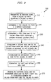
- FIG.1 depicts a flow chart of an embodiment of the present invention;
- FIG. 2 depicts a flow chart of another embodiment of the present invention;
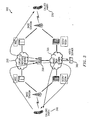
- FIG. 3 depicts a call flow supportive of the present invention;
- FIG. 4 depicts a flow chart of an aspect of the present invention;
- FIG. 5 depicts a flow chart of yet another embodiment of the present invention; and
- FIG. 6 depicts a flow chart of still another embodiment of the present invention.
- It should be emphasized that the drawings of the instant application are not to scale but are merely schematic representations, and thus are not intended to portray the specific dimensions of the invention, which may be determined by skilled artisans through examination of the disclosure herein.
- Referring to FIG. 1, a flow chart depicting one embodiment of the present invention is illustrated. Here, an
algorithmic method 100 is shown for use with multiple network types. More particularly,method 100 depicts a sequence of steps in providing a collaboration of a voice service(s), carried over a circuit-switched ("CS") type network, with multimedia service(s), carried over a packet-switched ("PS") type network. For the purposes of the present invention, a multimedia service(s) includes the delivery of multimedia content, such as a video clip(s), a web page(s), as well as data services, such as the delivery of a non-multimedia content type data file(s), for example. Moreover, it should be noted that providing collaboration of voice service(s) with multimedia service(s), as stated herein, includes communication between a calling-from-party and a calling-to-party, one or both of which may be directed from a wireless or wireline unit. -
Algorithmic method 100 initially provides for the step of transmitting an initiation signal from a calling-from-party (step 110). This initiation signal is received by a communication network infrastructure element, such as a service control point/service node (e.g., server), for example. The step of transmitting the initiation signal may include entering the telephone number of the calling-to-party into the temporary memory of the calling-from-party's wireless or wireline unit. Thereafter, a corresponding send button or the like on the calling-from-party's wireless or wireline unit may be depressed so as to commence the sequence of steps in formulating a telephonic connection between the calling-from- and calling-to- parties. Consequently, the initiation signal identifies the calling-to-party. - Once the initiation signal is received by the communication network infrastructure, such as a service control point/service node, for example, a determination is made regarding the calling-to-party's status. More particularly, the service control point/service node may determine if the calling-to-party is a subscriber to the collaboration of voice and multimedia services (step 120). This step of determining may include the step of looking up the telephone number of the calling-to-party in a database of service subscribers. If the calling-to-party is determined to be a service subscriber,
algorithmic method 100 proceeds as depicted in the flow chart of FIG. 1. However, if the telephone number is not found within a database, the remainder ofalgorithmic method 100 may be terminated. In this case, the initiation signal triggers either a voice link or data link (e.g., sessions) connecting the calling-from-party with the calling-to-party. - After the calling-to-party is deemed a service subscriber,
algorithmic method 100 may transmit multimedia content to the calling-from-party (step 130). Here, the calling-to-party's identity (e.g., telephone number) may trigger the transmission of multimedia content to the calling-from-party over a downlink channel, for example. This multimedia content may, for example, include commercial matter, such as advertising and/or marketing material, or general information, for example, selected in response to the calling-to-party's identity. - In one embodiment of
algorithmic method 100, the step of transmitting multimedia content may include establishing a data link (e.g., data session) in the event the calling-to-party is found to be a service subscriber. This established data link (e.g., data session) might be formed between the calling-from-party and the service control point/service node (e.g., server). Here, the service control point/service node, and thus, the established data link (e.g., data session) may serve as the sole resource for the step of transmitting multimedia content to the calling-from-party. It should be noted that this established data link (e.g., data session) might be rely on a packet switched ("PS") type network. - With the transfer of the multimedia content to calling-from-party,
algorithmic method 100 establishes an intermediate voice link to the calling-to-party (step 140). The intermediate voice link may be established by the service control point/service node supporting the transmissions of multimedia content to the calling-from-party. Moreover, the intermediate voice link may rely on a circuit switched ("CS") type network. - In furtherance of desire for a collaboration of data (e.g., multimedia) service, carried over a PS type network, with the of voice service, carried over a CS type network, for example, the service control point/service node may thereafter bridge the initiation signal and the intermediate voice link (step 150). Consequently, a voice call between the calling-from-party and the calling-to-party, as initiated at the onset of
algorithmic method 100, may be established and completed. It should be noted that this step of bridging may be performed after the transmission of multimedia content is concluded, though it is may also occur prior thereto. - Referring to FIG. 2, a flow chart depicting a further embodiment of the present invention is illustrated. Here, another
algorithmic method 200 is shown for use with multiple network types.Method 100 also depicts a sequence of steps in providing a collaboration of voice service(s), carried over a circuit-switched ("CS") type network, with multimedia service(s), carried over a packet-switched ("PS") type network. -
Algorithmic method 200 initially provides for the step of transmitting an initiation signal from a calling-from-party (step 110). This initiation signal is received by a communication network infrastructure element, such as a service control point/service node (e.g., server), for example. The step of transmitting the initiation signal may include entering the telephone number of the calling-to-party into the temporary memory of the calling-from-party's wireless or wireline unit. Thereafter, a corresponding send button or the like on the calling-from-party's wireless or wireline unit may be depressed so as to commence the sequence of steps in formulating a telephonic connection between the calling-from- and calling-to- parties. Consequently, the initiation signal identifies the calling-to-party. - Thereafter, a determination is made regarding the calling-to-party's identity. Here, the service control point/service node may determine if the calling-to-party is a subscriber to the collaboration of voice and multimedia services (step 220). This step of determining may include the step of looking up the telephone number of the calling-to-party in a database of service subscribers. If the calling-to-party is determined to be a service subscriber,
algorithmic method 200 proceeds as depicted in the flow chart of FIG. 2. In the alternative, should the telephone number of the calling-to-party not be found within a database, the offering of collaborative voice and multimedia services the remainder ofalgorithmic method 200 may be terminated. In this case, the initiation signal triggers either a voice link or data link (e.g., session) connecting the calling-from-party with the calling-to-party. - Once the calling-to-party is deemed a service subscriber,
algorithmic method 200 establishes a data link (e.g., data session) to the calling-from-party (step 230). Here, a uniform resource locator ("URL") may be selected in response to affirming if calling-to-party is a service subscriber. This URL may identify the location where multimedia content may be received by the calling-from-party over a downlink. It should be noted that the URL might be designated in advance by the calling-to-party, as part of the service subscription. - Subsequently,
algorithmic method 200 establishes another data link (e.g., data session) (step 240). With the URL information stored in memory, this subsequent data link (e.g., data session) may be used to forward the multimedia content, as intended by the calling-to-party, to the calling-from-party. Unlikealgorithmic method 100 of FIG. 1, this additional data link (e.g., data session) is intended in the scenario where the multimedia content cannot be transmitted over the same data link (e.g., data session) in which the URL is communicated. This may also arise, for example, if the multimedia content is stored in a network element physically separated from the network element storing the URL. - With the transmission and reception of the multimedia content,
algorithmic method 200 calls for establishing an intermediate voice link (step 250). This intermediate voice link is established to the calling-to-party. The intermediate voice link may be established by the service control point/service node supporting the transmissions of multimedia content to the calling-from-party. Moreover, the intermediate voice link may rely on a circuit switched ("CS") type network. - It should be noted that in order to manage communication network resources, the aforementioned data links (e.g., data sessions) should be terminated in a logical sequence (step 260). For example, the established data link (e.g., data session) for the transmission of the URL might be terminated in response to the establishing the intermediate voice link. Sometime thereafter, the established data link (e.g., data session) for the transmission of the multimedia content may also be terminated.
- In furtherance of desire for a collaboration of data (e.g., multimedia) service, carried over a PS type network, for example, with the voice service, carried over a CS type network, the service control point/service node may thereafter bridge the initiation signal and the intermediate voice link (step 270). Consequently, a voice call between the calling-from-party and the calling-to-party, as initiated at the onset of
algorithmic method 200, may be established and completed. It should be noted that this step of bridging may be performed after the transmission of multimedia content is concluded, though it is may also occur prior thereto. - The present invention may provide a framework for the creation of enhanced services utilizing simultaneous CS voice and PS data capabilities of the network. The present invention may be based on widely used telecommunication signaling technologies and Internet standards, such as a session initiation protocol ("SIP"), for example. The present invention may combine both in a manner that may minimize the impact to the existing network infrastructure.
- Referring to FIG. 3, a
call flow 300 supportive of the present invention is illustrated. To facilitatecall flow 300, a wireless circuit switched ("CS")network 310 and a wireless packet switched ("PS")network 320 may be included as part of a network configuration. The network configuration may also include a service control point/service node 330 (e.g., eMRS, which acts as both a SCP and SN) with a user information database formed therein, a first wireless unit supportive of simultaneous CS voice and PS data 340 (e.g., class A terminal), and avideo server 360 to supportcall flow 300. - To realize the present invention,
call flow 300 may process the call control whenfirst wireless unit 340 initiates a voice call toward a called (wireline or wireless)receiving unit 370. Alternatively,call flow 300 may process call control if it receives other triggers from the network - e.g., answer and/or disconnect. Depending on the nature of the trigger and the call state, the application of simultaneous CS voice and PS data may enable the performance of the appropriate tasks for the service, including, for example, initiating and/or terminating a data session. -
First wireless unit 340 may have a client application(s) for handling the needs of a service, such as a session initiation protocol ("SIP") stack to process the message, establishing a multimedia session, and for streaming video and/or audio, controls, for example. User database may store user, service subscription, network and/or session information for each user. The application servers may provide specific service subscriber resources - e.g., a video clip(s), a web page(s), a data file(s) - for the user. - In one example of the call flow, a calling-from-
party 340 may initiate a voice call to a calling-to-party 370 over circuit-switchednetwork 310. In turn, a Mobile Switching Center ("MSC") may then send the call control over to service control point/service node 330. Thereafter, service control point/service node 330 may determine if the calling-to-party 370 is a subscriber to the multimedia service (e.g., video greeting service). If so, service control point/service node 330 may transmit a video clip URL to the calling-from-party 340. This step may be realized through a SIP INVITE. Once the video clip URL is transmitted, calling-from-party 340 may receive the multimedia content associated with the URL fromvideo server 360.Video server 360, as a result, may send the multimedia content (e.g., video greeting) to the calling-from-party 340. Subsequently, service control point/service node 330 may initiate a voice call to calling-to-party 370. After calling-to-party 370 the voice call is established from service control point/service node 330, service control point/service node 330 may transmit a termination message (e.g., BYE) to calling-from-party 340 to terminate the SIP session in which the video clip may be transmitted. Thereafter, service control point/service node 330 may then bridge the two voice call legs together. Consequently, calling-from-party 340 and calling-to-party 370 may now have a complete voice conversation. - It should be noted that personal video greeting is merely one example of a multimedia service enabled by the present invention. This multimedia service may enable a subscriber to send a personalized video-greeting message to callers while the voice call is being connected. Referring to FIG. 4, a
message flow 400 is illustrated in accordance with an exemplary personal video greeting service enabled with this framework.Message flow 400 may include a sequence of process steps, as follows: - 1. Calling party (A) sets up a PDPContext;
- 2. Calling party (A) registers with a SIP registrar/server;
- 3. Calling party (A) initiated a voice call to called party (B), and the originating MSC queries the HLR for called party location and service subscription;
- 4. The GMSC detects the Termination Attempt Authorized trigger and sends an InitialDP message to the eMRS;
- 5. The eMRS (e.g., service control point/service node) queries a user database for subscriber and service subscription data - URL of the personal video, etc., and caller data, mapping of SIP URL to the caller MSISDN;
- 6. The eMRS responds with a Connect message;
- 7. The GMSC sends an IAM to extend the call to eMRS;
- 8. The eMRS responds with an ACM;
- 9. The eMRS initiates a SIP call to call party (A) by sending a INVITE message to calling party (A);
- 10. Calling party (A) responds with a trying message;
- 11. Calling party (A) responds with a ringing message;
- 12. Calling party (A) responds with an OK message;
- 13. The eMRS sends an ACK to calling party (A);
- 14. Calling party (A) requests video from the video server based on the URI included in the SIP message;
- 15. The video server streams the video greeting to calling party (A);
- 16. The eMRS initiates a new call to the called party by sending an IAM to the GMSC; and
- 17. The GMSC responds with an ACM.
- Referring to FIG. 5, a
message flow 500 is illustrated in accordance with an exemplary personal video greeting service enabled with this framework.Message flow 500 continues the sequence of steps depicted inflow 400 of FIG. 4 as follows: - 18. The GMSC exchange SendRoutingInfo (SRI) message with HLR;
- 19. The GMSC sends an InitialDP message to an eMRS (e.g., service control point/service node);
- 20. The eMRS responds with a Continue message;
- 21. The GMSC sends the IAM to the VMSC;
- 22. The VMSC responds with an ACM;
- 23. The VMSC sets up the call to called party (B);
- 24. The called party answers;
- 25. The VMSC sends an ANM to the GMSC;
- 26. The GMSC informs eMRS that the called party answered with an ANM;
- 27. The eMRS hairpins the two call legs and sends an ANM to the GMSC on the calling party leg;
- 28. The eMRS sends a BYE message to the calling party (A) to terminate the SIP session. The SIP application then closes the video viewer; and
- 29. The voice communication begins.
- Referring to FIG. 6, a
message flow 600 is illustrated in accordance with another exemplary approach.Message flow 600 is reflected in the following steps: - 28. The voice communication begins;
- 29. The eMRS sends a re-Invite message with the URL of the application(s) to calling party (A);
- 30. The calling party (A) responds with an OK message;
- 31. The eMRS sends an ACK to calling party (A);
- 32. The calling party (A) request the URL of the application;
- 33. The application sends the response back to calling party (A); and
- 34. The calling party (A) sends a Bye message to the eMRS.
- It should be noted that the principles reflected in the personal video greeting service detailed herein, for example, may be extended to other applications. Exemplary alternative applications may include on-line browsing/shopping with operator assistance. Referring to FIG. 7, a
message flow 700 is shown.Message flow 700 illustrates a methodology for invoking an alternative application(s) after the initial video greeting is complete.Message flow 700, incorporating the sequence of steps for delivering the personal video greeting, as depicted in message flow 400 of FIG. 4 and flow 500 of FIG. 5, also includes the following additional steps: - 28. The voice communication begins;
- 29. The eMRS (e.g., service control point/service node) sends a REFER message with the URL of the application(s) to calling party (A);
- 30. The calling party (A) responds with an ACCEPTED message;
- 31. The calling party (A) responds with a NOTIFY message;
- 32. The eMRS sends an OK to calling party (A);
- 33. The calling party (A) request the URL of the application;
- 34. The application sends the response back to calling party (A);
- 35. The calling party (A) sends a NOTIFY message to the eMRS;
- 36. The eMRS responds with an OK message; and
- 37. The eMRS sends a BYE message to the calling party (A).
- While the particular invention has been described with reference to illustrative embodiments, this description is not meant to be construed in a limiting sense. It is understood that although the present invention has been described, various modifications of the illustrative embodiments, as well as additional embodiments of the invention, will be apparent to one of ordinary skill in the art upon reference to this description without departing from the scope of the invention, as recited in the claims appended hereto. Consequently, the method, system and portions thereof and of the described method and system may be implemented in different locations, such as the wireless unit, the base station, a base station controller and/or mobile switching center. Moreover, processing circuitry required to implemenf and use the described system may be implemented in application specific integrated circuits, software-driven processing circuitry, firmware, programmable logic devices, hardware, discrete components or arrangements of the above components as would be understood by one of ordinary skill in the art with the benefit of this disclosure. Those skilled in the art will readily recognize that these and various other modifications, arrangements and methods can be made to the present invention without strictly following the exemplary applications illustrated and described herein and without departing from the scope of the present invention It is therefore contemplated that the appended claims will cover any such modifications or embodiments as fall within the scope of the invention.
Claims (10)
- A method of communication between a calling-from-party (340) and a calling-to-party (370), the method comprising:enabling a data service over a first type of network (320) to operate with a voice service over a second type of network (310) different than the first type of network (320);transmitting a uniform resource locator to the calling-from-party (340) in response to an initiation signal from the calling-from-party (340);determining if the calling-to-party (370) is a service subscriber of the data service to receive multimedia content from the calling-from-party (340); andestablishing a voice link to the calling-to-party (370) in response to the initiation signal from the calling-from-party (340).
- The method of Claim 1, wherein the uniform resource locator identifies a location for a multimedia content, and wherein the step of transmitting a uniform resource locator comprises:establishing a first data session for downloading the multimedia content;looking up the calling-to-party(370) in a database (350) of service subscribers; andselecting the uniform resource locator if the calling-to-party (370) is at least one of the service subscribers in the database (350).
- A method of communication with a calling-to-party (370), the method comprising:receiving a uniform resource locator associated with the calling-to-party (370) from a video server (360) in response to an initiation signal from a calling-from party (340);enabling the calling-from-party (340) to determine whether the calling-to-party (370) is a service subscriber of a multimedia service; andestablishing a first data session from a service controlling node (330) to the calling-from-party (340) in response to the received uniform resource locator.
- The method of Claim 3, wherein the step of receiving a uniform resource locator comprises:establishing a second data session for receiving the uniform resource locator.
- The method of Claim 4, wherein the uniform resource locator identifies a location for multimedia content to be received over the second data session, the multimedia content received over the second data session if the calling-to-party (370) is a service subscriber of a multimedia service, the method comprising:bridging the initiation signal from the calling-from party into a voice link from the calling-from-party (340) to the calling-to-party (370);terminating the established second data session prior to the step of bridging the initiation signal; andterminating the established first data session after the step of terminating the established second data session.
- A method of communication with a calling-from-party (340), the method comprising:selecting multimedia content associated with a calling-to-party (370) to be forwarded to the calling-from-party (340) in response to identifying the calling-to-party (370), the multimedia content selected if the calling-to-party (370) is a service subscriber of a data service to receive multimedia content; andestablishing a voice link from the calling-from-party to the calling-to-party (370) in response to the identifying the calling-to-party (370) based on an initiation signal from the calling-from-party (340).
- A method of communication between a calling-from-party (340) and a calling-to-party (370), the method comprising:enabling a data service over a first type of network (320) to operate with a voice service over a second type of network (310) different than the first type of network (320);receiving an initiation signal from the calling-from-party (340) identifying the calling-to-party (370);determining if the calling-to-party(370) is a service subscriber of the data service to receive multimedia content;transmitting multimedia content to the calling-from-party (340), the multimedia content selected in response to the identifying of the calling-to-party (370) to be a service subscriber of the data service to receive the multimedia content; andestablishing a voice link to the calling-to-party (370) in response to the initiation signal from the calling-from-party (340).
- The method of Claims 1 or 7, comprising:bridging the initiation signal from the calling-from-party(340) with the established voice link to the calling-to-party (370).
- The method of Claim 7, wherein a uniform resource locator identifies a location for the selected multimedia content to be received from, and the step of transmitting multimedia content comprises:transmitting a uniform resource locator;looking up the calling-to-party (370) in a database (350) of service subscribers;selecting the uniform resource locator if the calling-to-party (370) is at least one of the service subscribers in the database (350); andestablishing a first data session for the transmission of the multimedia content.
- The method of Claims 2 or 9, wherein the step of transmitting a uniform resource locator comprises:establishing a second data session for transmitting the uniform resource locator to the calling-from-party (340);terminating the established second data session in response to the step of establishing a voice link to the calling-to-party (370); andterminating the established first data session after the step of terminating the established second data session.
Applications Claiming Priority (2)
| Application Number | Priority Date | Filing Date | Title |
|---|---|---|---|
| US783308 | 2004-02-20 | ||
| US10/783,308 US20050185771A1 (en) | 2004-02-20 | 2004-02-20 | Method of delivering multimedia associated with a voice link |
Publications (2)
| Publication Number | Publication Date |
|---|---|
| EP1566984A1 EP1566984A1 (en) | 2005-08-24 |
| EP1566984B1 true EP1566984B1 (en) | 2007-06-27 |
Family
ID=34711875
Family Applications (1)
| Application Number | Title | Priority Date | Filing Date |
|---|---|---|---|
| EP05250718A Expired - Lifetime EP1566984B1 (en) | 2004-02-20 | 2005-02-08 | A method of delivering multimedia associated with a voice link |
Country Status (6)
| Country | Link |
|---|---|
| US (1) | US20050185771A1 (en) |
| EP (1) | EP1566984B1 (en) |
| JP (1) | JP2005237011A (en) |
| KR (1) | KR20060042977A (en) |
| CN (1) | CN1697534A (en) |
| DE (1) | DE602005001455T2 (en) |
Cited By (1)
| Publication number | Priority date | Publication date | Assignee | Title |
|---|---|---|---|---|
| WO2024079746A1 (en) * | 2022-10-12 | 2024-04-18 | Rajender Kumar Nangia | Method and system of rendering multimedia content during call establishment |
Families Citing this family (17)
| Publication number | Priority date | Publication date | Assignee | Title |
|---|---|---|---|---|
| US7852828B2 (en) * | 2002-08-07 | 2010-12-14 | Cisco Technology, Inc. | Extended telephony functionality at end points |
| US20060104259A1 (en) * | 2004-11-15 | 2006-05-18 | Cisco Technology, Inc. | System and method for executing a multi-modal transfer in a session initiation protocol (SIP) environment |
| US8068593B2 (en) * | 2004-12-30 | 2011-11-29 | Alcatel Lucent | Method and apparatus for providing multimedia ringback services to mobile user devices in pre-IMS networks |
| US7693134B2 (en) * | 2004-12-30 | 2010-04-06 | Alcatel-Lucent Usa Inc. | Method and apparatus for providing multimedia ringback services to user devices in IMS networks |
| US20070121595A1 (en) * | 2005-11-30 | 2007-05-31 | Batni Ramachendra P | Method and apparatus for providing customized ringback to calling party devices in an IMS network |
| KR101247985B1 (en) * | 2006-06-09 | 2013-03-27 | 에스케이텔레콤 주식회사 | Method for providing early-media service based on session initiation protocol using early session |
| US8270590B2 (en) * | 2006-06-15 | 2012-09-18 | Alcatel Lucent | User message delivery to calling party device |
| US20070294263A1 (en) * | 2006-06-16 | 2007-12-20 | Ericsson, Inc. | Associating independent multimedia sources into a conference call |
| CN100454906C (en) * | 2006-07-04 | 2009-01-21 | 华为技术有限公司 | Method and gateway for transmitting voice stream based on network bearer in wireless packet network |
| CN1949889B (en) * | 2006-11-01 | 2010-09-29 | 华为技术有限公司 | A method and device for realizing call service |
| CN101277343B (en) * | 2007-03-30 | 2012-01-04 | 华为技术有限公司 | Method, terminal and system for implementing video binding in voice communication network |
| CN101217822B (en) * | 2008-01-17 | 2011-12-07 | 中兴通讯股份有限公司 | A method and system for transferring multimedia data information of caller in combined operations |
| US20090199255A1 (en) * | 2008-01-31 | 2009-08-06 | At&T Knowledge Ventures, Lp | Device and Methods for Customization of Communication Notification In A Converged Network |
| US20090316865A1 (en) * | 2008-06-20 | 2009-12-24 | Jones David A | Method for providing green service to a communication unit |
| US10812937B2 (en) | 2008-12-11 | 2020-10-20 | Qualcomm Incorporated | Method and apparatus for obtaining contextually relevant content |
| WO2010127478A1 (en) * | 2009-05-04 | 2010-11-11 | 华为技术有限公司 | Switch method and equipment |
| PL2405638T3 (en) * | 2010-07-08 | 2015-08-31 | Deutsche Telekom Ag | Method and system for audio-visual telecommunication |
Family Cites Families (9)
| Publication number | Priority date | Publication date | Assignee | Title |
|---|---|---|---|---|
| US5978806A (en) * | 1997-02-18 | 1999-11-02 | Ameritech Corporation | Method and apparatus for communicating information about a called party to a calling party |
| US6222826B1 (en) * | 1997-11-19 | 2001-04-24 | Lucent Technologies Inc. | Multimedia calling method and apparatus |
| US6480484B2 (en) * | 1998-06-09 | 2002-11-12 | Avaya Technology Corp. | Internet-intranet greeting service |
| KR100325961B1 (en) * | 1999-07-16 | 2002-03-07 | Information providing method and apparatus using waiting time of incoming call response in communication system | |
| FR2810827B1 (en) * | 2000-06-23 | 2002-10-31 | France Telecom | METHOD FOR TRANSMITTING INFORMATION, ESPECIALLY ADVERTISING INFORMATION, ON A USER TERMINAL |
| US6603840B2 (en) * | 2000-12-06 | 2003-08-05 | At&T Corp. | Technique for linking telephony and multimedia information |
| GB0110542D0 (en) * | 2001-04-30 | 2001-06-20 | Nokia Corp | Messaging system |
| JP3873697B2 (en) * | 2001-10-01 | 2007-01-24 | 日本電気株式会社 | Transmission device and transmission / reception device, transmission program and transmission / reception program |
| US6934369B2 (en) * | 2003-03-31 | 2005-08-23 | Nortel Networks Limited | White and yellow page multimedia service |
-
2004
- 2004-02-20 US US10/783,308 patent/US20050185771A1/en not_active Abandoned
-
2005
- 2005-02-08 EP EP05250718A patent/EP1566984B1/en not_active Expired - Lifetime
- 2005-02-08 DE DE602005001455T patent/DE602005001455T2/en not_active Expired - Lifetime
- 2005-02-18 CN CNA200510009383XA patent/CN1697534A/en active Pending
- 2005-02-18 KR KR1020050013494A patent/KR20060042977A/en not_active Withdrawn
- 2005-02-18 JP JP2005041476A patent/JP2005237011A/en active Pending
Non-Patent Citations (1)
| Title |
|---|
| None * |
Cited By (1)
| Publication number | Priority date | Publication date | Assignee | Title |
|---|---|---|---|---|
| WO2024079746A1 (en) * | 2022-10-12 | 2024-04-18 | Rajender Kumar Nangia | Method and system of rendering multimedia content during call establishment |
Also Published As
| Publication number | Publication date |
|---|---|
| DE602005001455T2 (en) | 2008-02-28 |
| US20050185771A1 (en) | 2005-08-25 |
| KR20060042977A (en) | 2006-05-15 |
| EP1566984A1 (en) | 2005-08-24 |
| JP2005237011A (en) | 2005-09-02 |
| CN1697534A (en) | 2005-11-16 |
| DE602005001455D1 (en) | 2007-08-09 |
Similar Documents
| Publication | Publication Date | Title |
|---|---|---|
| US8717876B2 (en) | Providing packet-based multimedia services via a circuit bearer | |
| EP1566984A1 (en) | A method of delivering multimedia associated with a voice link | |
| US7904068B2 (en) | System and method for providing integrated voice and data services utilizing wired cordless access with unlicensed spectrum and wired access with licensed spectrum | |
| KR100701637B1 (en) | Circuit Switched and Packet Switched Communications | |
| US7876743B2 (en) | Conversational bearer negotiation | |
| US10368209B2 (en) | Routing multiple numbers for one telecommunications device | |
| US20070053343A1 (en) | Conversational bearer negotiation | |
| JP2004312738A (en) | Fast network sip/sdp procedures for conference administration upon request from end user with optimization of network resources | |
| CN1993972B (en) | Method and system for retrieving network addresses in hybrid telecommunication networks | |
| EP1487221A1 (en) | Server component redirection of new media path portion between packet-switched and circuit-switched portions of mobile switching center | |
| JP2007528157A (en) | Domain ID mapping for wireless device identifier | |
| EP2184945A1 (en) | Redirection during call set-up in a communication network | |
| EP1736015B1 (en) | System and method for providing early ringback by a home legacy mobile station domain network | |
| KR101407383B1 (en) | Method, server and terminal device for playing multimedia ring tone during call | |
| US9615230B2 (en) | Method to manage multiple caller identities in a telecommunication system | |
| EP1849286B1 (en) | Method and apparatuses for routing or redirecting video traffic in communications system | |
| CN101668229A (en) | Method, device and system for calling and controlling multimedia ringtone service | |
| US8254919B2 (en) | Selectively terminating CAMEL dialogues | |
| KR20060010071A (en) | File Transfer System and Method During Voice Call | |
| CN101646271B (en) | Method, device and system for realizing multimedia services before answering | |
| CN100396113C (en) | Implementation method of concurrent voice service after inter-office handover | |
| KR100844396B1 (en) | Video call connection service system and method | |
| CN102056110A (en) | Method, system and device for 2-generation (2G) communication system and IP multimedia subsystem (IMS) communication system to share ring back tone service | |
| WO2005069580A1 (en) | Controlling data sessions in a communication system | |
| CN101656919A (en) | Method for implementing satisfaction investigation, ring back tone server and terminal |
Legal Events
| Date | Code | Title | Description |
|---|---|---|---|
| PUAI | Public reference made under article 153(3) epc to a published international application that has entered the european phase |
Free format text: ORIGINAL CODE: 0009012 |
|
| 17P | Request for examination filed |
Effective date: 20050221 |
|
| AK | Designated contracting states |
Kind code of ref document: A1 Designated state(s): AT BE BG CH CY CZ DE DK EE ES FI FR GB GR HU IE IS IT LI LT LU MC NL PL PT RO SE SI SK TR |
|
| AX | Request for extension of the european patent |
Extension state: AL BA HR LV MK YU |
|
| AKX | Designation fees paid |
Designated state(s): DE FR GB |
|
| 17Q | First examination report despatched |
Effective date: 20050902 |
|
| GRAP | Despatch of communication of intention to grant a patent |
Free format text: ORIGINAL CODE: EPIDOSNIGR1 |
|
| GRAS | Grant fee paid |
Free format text: ORIGINAL CODE: EPIDOSNIGR3 |
|
| GRAA | (expected) grant |
Free format text: ORIGINAL CODE: 0009210 |
|
| AK | Designated contracting states |
Kind code of ref document: B1 Designated state(s): DE FR GB |
|
| REG | Reference to a national code |
Ref country code: GB Ref legal event code: FG4D |
|
| REF | Corresponds to: |
Ref document number: 602005001455 Country of ref document: DE Date of ref document: 20070809 Kind code of ref document: P |
|
| ET | Fr: translation filed | ||
| PLBE | No opposition filed within time limit |
Free format text: ORIGINAL CODE: 0009261 |
|
| STAA | Information on the status of an ep patent application or granted ep patent |
Free format text: STATUS: NO OPPOSITION FILED WITHIN TIME LIMIT |
|
| 26N | No opposition filed |
Effective date: 20080328 |
|
| REG | Reference to a national code |
Ref country code: GB Ref legal event code: 732E Free format text: REGISTERED BETWEEN 20131107 AND 20131113 |
|
| REG | Reference to a national code |
Ref country code: FR Ref legal event code: CD Owner name: ALCATEL-LUCENT USA INC. Effective date: 20131122 |
|
| REG | Reference to a national code |
Ref country code: FR Ref legal event code: GC Effective date: 20140410 |
|
| REG | Reference to a national code |
Ref country code: FR Ref legal event code: RG Effective date: 20141015 |
|
| REG | Reference to a national code |
Ref country code: FR Ref legal event code: PLFP Year of fee payment: 11 |
|
| REG | Reference to a national code |
Ref country code: FR Ref legal event code: PLFP Year of fee payment: 12 |
|
| REG | Reference to a national code |
Ref country code: FR Ref legal event code: PLFP Year of fee payment: 13 |
|
| PGFP | Annual fee paid to national office [announced via postgrant information from national office to epo] |
Ref country code: FR Payment date: 20170217 Year of fee payment: 13 |
|
| PGFP | Annual fee paid to national office [announced via postgrant information from national office to epo] |
Ref country code: GB Payment date: 20180216 Year of fee payment: 14 Ref country code: DE Payment date: 20180219 Year of fee payment: 14 |
|
| REG | Reference to a national code |
Ref country code: FR Ref legal event code: ST Effective date: 20181031 |
|
| REG | Reference to a national code |
Ref country code: GB Ref legal event code: 732E Free format text: REGISTERED BETWEEN 20190131 AND 20190206 |
|
| PG25 | Lapsed in a contracting state [announced via postgrant information from national office to epo] |
Ref country code: FR Free format text: LAPSE BECAUSE OF NON-PAYMENT OF DUE FEES Effective date: 20180228 |
|
| REG | Reference to a national code |
Ref country code: DE Ref legal event code: R081 Ref document number: 602005001455 Country of ref document: DE Owner name: PROVENANCE ASSET GROUP LLC, PITTSFORD, US Free format text: FORMER OWNER: LUCENT TECHNOLOGIES INC., MURRAY HILL, N.J., US |
|
| REG | Reference to a national code |
Ref country code: DE Ref legal event code: R081 Ref document number: 602005001455 Country of ref document: DE Owner name: PROVENANCE ASSET GROUP LLC, PITTSFORD, US Free format text: FORMER OWNER: NOKIA OF AMERICA CORP. (N. D. GES. D. STAATES DELAWARE), MURRAY HILL, NJ, US Ref country code: DE Ref legal event code: R081 Ref document number: 602005001455 Country of ref document: DE Owner name: PROVENANCE ASSET GROUP LLC, PITTSFORD, US Free format text: FORMER OWNER: ALCATEL-LUCENT USA INC. (N. D. GES. D. STAATES DELAWARE), MURRAY HILL, N.J., US |
|
| REG | Reference to a national code |
Ref country code: DE Ref legal event code: R119 Ref document number: 602005001455 Country of ref document: DE |
|
| GBPC | Gb: european patent ceased through non-payment of renewal fee |
Effective date: 20190208 |
|
| PG25 | Lapsed in a contracting state [announced via postgrant information from national office to epo] |
Ref country code: DE Free format text: LAPSE BECAUSE OF NON-PAYMENT OF DUE FEES Effective date: 20190903 Ref country code: GB Free format text: LAPSE BECAUSE OF NON-PAYMENT OF DUE FEES Effective date: 20190208 |