EP1566881A1 - Controller of ac generator for vehicle - Google Patents
Controller of ac generator for vehicle Download PDFInfo
- Publication number
- EP1566881A1 EP1566881A1 EP02788663A EP02788663A EP1566881A1 EP 1566881 A1 EP1566881 A1 EP 1566881A1 EP 02788663 A EP02788663 A EP 02788663A EP 02788663 A EP02788663 A EP 02788663A EP 1566881 A1 EP1566881 A1 EP 1566881A1
- Authority
- EP
- European Patent Office
- Prior art keywords
- generator
- voltage
- controller
- temperature
- rotational speed
- Prior art date
- Legal status (The legal status is an assumption and is not a legal conclusion. Google has not performed a legal analysis and makes no representation as to the accuracy of the status listed.)
- Granted
Links
Images


Classifications
-
- H—ELECTRICITY
- H02—GENERATION; CONVERSION OR DISTRIBUTION OF ELECTRIC POWER
- H02P—CONTROL OR REGULATION OF ELECTRIC MOTORS, ELECTRIC GENERATORS OR DYNAMO-ELECTRIC CONVERTERS; CONTROLLING TRANSFORMERS, REACTORS OR CHOKE COILS
- H02P9/00—Arrangements for controlling electric generators for the purpose of obtaining a desired output
- H02P9/14—Arrangements for controlling electric generators for the purpose of obtaining a desired output by variation of field
- H02P9/26—Arrangements for controlling electric generators for the purpose of obtaining a desired output by variation of field using discharge tubes or semiconductor devices
- H02P9/30—Arrangements for controlling electric generators for the purpose of obtaining a desired output by variation of field using discharge tubes or semiconductor devices using semiconductor devices
-
- H—ELECTRICITY
- H02—GENERATION; CONVERSION OR DISTRIBUTION OF ELECTRIC POWER
- H02P—CONTROL OR REGULATION OF ELECTRIC MOTORS, ELECTRIC GENERATORS OR DYNAMO-ELECTRIC CONVERTERS; CONTROLLING TRANSFORMERS, REACTORS OR CHOKE COILS
- H02P9/00—Arrangements for controlling electric generators for the purpose of obtaining a desired output
- H02P9/14—Arrangements for controlling electric generators for the purpose of obtaining a desired output by variation of field
- H02P9/26—Arrangements for controlling electric generators for the purpose of obtaining a desired output by variation of field using discharge tubes or semiconductor devices
- H02P9/30—Arrangements for controlling electric generators for the purpose of obtaining a desired output by variation of field using discharge tubes or semiconductor devices using semiconductor devices
- H02P9/305—Arrangements for controlling electric generators for the purpose of obtaining a desired output by variation of field using discharge tubes or semiconductor devices using semiconductor devices controlling voltage
Definitions
- the present invention relates to a controller of an A.C. generator for vehicles.
- a conventional controller of an A.C. generator for vehicles controlled a duty ratio of a switching element for intermittently controlling a field current of a generator to thereby limit the field current so as for the field current not to exceed a predetermined limitation value.
- the predetermined limitation value is selected so as to become a value equal to or larger than a value of a field current which is to be caused to flow in order to obtain a predetermined output from the generator when a temperature of a generator has risen up to a predetermined value (refer to JP 6-38720 B (page 2 and FIG. 1)).
- the present invention has been made to solve the above-mentioned problems, and it is an object of the present invention that after the rotational speed of the generator exceeds the predetermined value, an increase in output of the generator is suppressed, whereby it is possible to realize the miniaturized controller of an A.C. generator for vehicles (car, and the like) which is capable of preventing the heating of the armature coil, the rectifier and the like, and hence which requires no cooling fan.
- a controller of an A.C. generator for vehicles includes: a switching element inserted in series in a field coil of an A.C. generator for intermittently controlling a field current supplied to the field coil in accordance with an output voltage from the A.C. generator in order to control the output voltage from the A.C. generator to a predetermined value; and conduction rate control means for detecting a rotational speed of the A.C. generator to reduce a conduction rate of the switching element in accordance with an increase in rotational speed.
- FIG. 1 is a circuit diagram of a controller of anA.C. generator for vehicles according to Embodiment 1 of the present invention.
- a generator for vehicles hereinafter referred to as "a generator” for short when applicable
- a rectifier 2 for subjecting an A.C. output of the generator 1 to full wave rectification has a main output terminal 201 and a grounding terminal 202.
- a voltage regulator 3 for regulating an output voltage of the generator 1 to a predetermined value includes voltage division resistors 301 and 302 for detecting a voltage which serve to voltage-dividing an output voltage obtained through the main output terminal 201 of the rectifier 2 to detect a resultant voltage.
- a constant voltage power supply circuit 300 provides a constant voltage source A on the basis of an electric power which is supplied from a battery 5 by turning ON a key switch 4.
- a constant voltage of the constant voltage source A is divided through voltage division resistors 303 and 304 for generating a reference voltage to generate a reference voltage.
- a comparator 305 compares the detected voltage obtained through the voltage division in the voltage division resistors 301 and 302 for detecting a voltage with the reference voltage generated through the voltage division resistors 303 and 304 for generating a reference voltage.
- a power transistor (switching element) 307 is inserted in series in the field coil 102.
- the controller for an A.C. generator for vehicles according to Embodiment 1 includes a conduction rate control circuit (conduction rate control means) 312 for controlling a conduction rate of the power transistor 307.
- the conduction rate control circuit 302 has an f-V converter 309 for converting a frequency proportional to a rotational speed obtained on the basis of one-phase output from the armature coil 101 into a voltage, a triangular waveform generator 310 for generating a voltage having a triangular waveform, and a comparator 311 for comparing the f-V conversion voltage value obtained through the f-V conversion in the f-V converter 309 with the voltage having a triangular waveform generated from the triangular waveform generator.
- the comparator 305 outputs an output signal at a "High” level when the detection voltage of the generator 1 detected by the voltage division resistors 301 and 302 for detecting a voltage is lower in level than a predetermined value set using the resistors 303 and 304 for generating a reference voltage, and outputs an output signal at a "Low” level when the detection voltage is higher in level than the reference voltage.
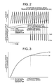
- an upper stage of FIG. 2 is a waveform chart showing a waveform of an input signal of the comparator 311, i.e., a waveform of an output signal of the triangular waveform generator 310 (an axis of abscissas represents an axis of time), and a waveform of an output signal of the f-V converter 309 (an axis of abscissas represents an axis of a rotational speed of the generator).
- the comparator 311 compares the voltage level of the f-V conversion voltage value with the voltage level of the voltage having a triangular waveform generated by the triangular waveform generator 310.
- the comparator 311 outputs an output signal at a "High” level when after the rotational speed of the generator 1 has exceeded a predetermined rotational speed, the voltage level of the f-V conversion voltage value does not exceed the voltage level of the voltage having a triangular waveform, and outputs an output signal at a "Low” level when after the rotational speed of the generator 1 has exceeded a predetermined rotational speed, the voltage level of the f-V conversion voltage value exceeds the voltage level of the voltage having a triangular waveform.
- FIG. 3 is a graphical representation for comparison between output current characteristics of generators controlled by the controllers for anA.C. generator for vehicles.
- a curve (a) represents the output characteristics of the generator according to Embodiment 1 of the present invention
- a curve (b) represents the output characteristics of a conventional generator. From FIG. 3 as well, it is understood that the output current of the generator according to Embodiment 1 is suppressed so as not to be increased even when the number of rotations of the generator 1 exceeds the predetermined rotational speed.
- the conduction rate of the power transistor 307 is reduced in accordance with an increase in rotational speed to reduce the field current, whereby it is possible to obtain the output current characteristics in which even when the number of rotations of the generator 1 becomes equal to or larger than the predetermined rotational speed, the output current is suppressed so as not to be increased.
- the heating of the armature coil, the rectifier and the like can be prevented, and hence no cooling fan is required. Consequently, miniaturization can be realized.
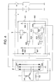
- FIG. 4 is a circuit diagram of a controller of an A.C. generator for vehicles according to Embodiment 2 of the present invention.
- the controller of Embodiment 2 has such a configuration as to newly provide a temperature detector 313 in the conduction rate control circuit 312 in addition to the constituent elements of the configuration shown in FIG. 1.
- FIGS. 5 to 7 show examples of concrete configurations of the above-mentioned temperature detector 313.
- FIG. 5 shows the temperature detector 313 including a thermosensitive semiconductor element
- FIG. 6 shows the temperature detector 313 including a thermosensitive resistance element having a positive resistance temperature coefficient
- FIG. 7 shows the temperature detector 313 including a thermosensitive element having a negative resistance temperature coefficient.
- a diode 312a serving as the thermosensitive semiconductor element and a resistor 312b are inserted in series between the constant voltage source A and the earth to be adapted to detect a temperature change voltage obtained on the basis of a change in temperature of the diode 312a.
- voltage division resistors 312c and 312d similarly, are inserted between the constant voltage source A and the earth to be adapted to generate a reference voltage from the constant voltage source A. The reference voltage and the temperature change voltage which are obtained in such a manner are compared with each other in a comparator 312e.
- the reference voltage (a minus input voltage of the comparator 312e) is set so as to be higher than the temperature change voltage (a plus input voltage of the comparator 312e), and hence the comparator 312e outputs an output signal at a "Low” level.
- the plus input voltage of the comparator 312e is increased in level due to negative temperature characteristics of an internal voltage drop developed across the diode 312a to exceed the reference voltage (the minus input voltage), which results in that the comparator 312e outputs an output signal at a "High” level.
- FIG. 6 a point of difference in configuration with FIG. 5 is that a resistor 312f and a posistor 312g serving as a thermosensitive resistance element having a positive resistance temperature coefficient are provided for detection of the temperature change voltage instead of the diode 312a serving as the thermosensitive semiconductor element and the resistor 312b.
- a resistor 312f is connected to the side of the constant voltage source A. Consequently, similarly to the case of FIG. 5, the comparator 312e normally outputs an output signal at a "Low" level.
- the plus input voltage of the comparator 312e is increased in level due to positive resistance temperature coefficient characteristics of the posistor 312g to exceed the reference voltage (minus input voltage), which results in that the comparator 312e outputs an output signal at a "High" level.
- a point of difference in configuration with FIG. 6 is that a thermistor 312h having a negative resistance temperature coefficient and a resistor 312i are provided instead of the resistor 312f and the posistor 312g serving as the thermosensitive resistance element having a positive resistance temperature coefficient.
- the thermistor 312h is connected to the side of the constant voltage source A. Consequently, similarly to the cases of FIGS. 5 and 6, the comparator 312e normally outputs an output signal at a "Low" level.
- the plus input voltage of the comparator 312e is increased in level due to the negative resistance temperature coefficient characteristics of the thermistor 312h to exceed the reference voltage (minus input voltage). As a result, the comparator 312e outputs the output signal at a "High" level.
- the output signal at a "High" level is outputted from the temperature detector 313, the output signal of the f-V converter 309 becomes valid.
- the temperature detector 313 is provided to thereby allow a temperature limitation to be given.
- the present invention after the rotational speed of the generator exceeds the predetermined value, an increase in output of the generator is suppressed, whereby it is possible to realize the miniaturized controller of an A. C. generator for vehicles which is capable of preventing the heating of the armature coil, the rectifier and the like, and hence which requires no cooling fan.
Landscapes
- Engineering & Computer Science (AREA)
- Power Engineering (AREA)
- Control Of Eletrric Generators (AREA)
Abstract
Description
Claims (6)
- A controller of an A.C. generator for vehicles, comprising:a switching element inserted in series in a field coil of an A.C. generator for intermittently controlling a field current supplied to the field coil in accordance with an output voltage from the A.C. generator; andconduction rate control means for detecting a rotational speed of the A.C. generator to control a conduction rate of the switching element in accordance with an increase in rotational speed.
- A controller of an A.C. generator for vehicles according to claim 1, wherein the conduction rate control means comprises:an f-V converter for converting a frequency proportional to the rotational speed of the A.C. generator into a voltage;a triangular waveform generator for generating and outputting a predetermined triangular waveform; anda comparator for controlling the conduction rate of the switching element in accordance with a magnitude relationship between a level of the voltage obtained through the f-V conversion in the f-V converter and a level of the triangular waveform and which is outputted from the triangular waveform generator.
- A controller of an A.C. generator for vehicles according to claim 2, wherein the conduction rate control means further comprises temperature detection means for detecting a temperature of a predetermined position of the A.C. generator, and the temperature detection means, when a detected temperature is equal to or higher than a predetermined temperature, operates the f-V converter.
- A controller of an A.C. generator for vehicles according to claim 3, wherein the temperature detection means comprises a thermosensitive semiconductor element.
- A controller of an A.C. generator for vehicles according to claim 3, wherein the temperature detection means comprises a thermosensitive resistance element having a positive resistance temperature coefficient.
- A controller of an A.C. generator for vehicles according to claim 3, wherein the temperature detection means comprises a thermosensitive resistance element having a negative resistance temperature coefficient.
Applications Claiming Priority (1)
| Application Number | Priority Date | Filing Date | Title |
|---|---|---|---|
| PCT/JP2002/012325 WO2004049553A1 (en) | 2002-11-26 | 2002-11-26 | Controller of ac generator for vehicle |
Publications (3)
| Publication Number | Publication Date |
|---|---|
| EP1566881A1 true EP1566881A1 (en) | 2005-08-24 |
| EP1566881A4 EP1566881A4 (en) | 2006-07-19 |
| EP1566881B1 EP1566881B1 (en) | 2007-11-07 |
Family
ID=32375606
Family Applications (1)
| Application Number | Title | Priority Date | Filing Date |
|---|---|---|---|
| EP02788663A Expired - Lifetime EP1566881B1 (en) | 2002-11-26 | 2002-11-26 | Controller of ac generator for vehicle |
Country Status (8)
| Country | Link |
|---|---|
| US (1) | US7106028B2 (en) |
| EP (1) | EP1566881B1 (en) |
| JP (1) | JP4480583B2 (en) |
| KR (1) | KR100674351B1 (en) |
| CN (1) | CN1625832A (en) |
| AU (1) | AU2002368382B2 (en) |
| DE (1) | DE60223421T2 (en) |
| WO (1) | WO2004049553A1 (en) |
Families Citing this family (20)
| Publication number | Priority date | Publication date | Assignee | Title |
|---|---|---|---|---|
| DE10361215A1 (en) * | 2003-12-24 | 2005-07-28 | Daimlerchrysler Ag | Electrical device and operating method |
| JP2005268578A (en) * | 2004-03-19 | 2005-09-29 | Toudai Tlo Ltd | Thermistor element |
| JP4151642B2 (en) * | 2004-10-25 | 2008-09-17 | 株式会社デンソー | Vehicle power generation control system |
| JP4124209B2 (en) * | 2005-03-23 | 2008-07-23 | 株式会社デンソー | Power generation control device |
| JP4017637B2 (en) * | 2005-04-21 | 2007-12-05 | 三菱電機株式会社 | Control device for vehicle generator |
| TWI288998B (en) * | 2005-12-21 | 2007-10-21 | Prolific Technology Inc | Driving circuit of a fan |
| JP4367416B2 (en) * | 2006-01-13 | 2009-11-18 | 国産電機株式会社 | Battery charge control device |
| US7635922B2 (en) * | 2006-04-03 | 2009-12-22 | C.E. Niehoff & Co. | Power control system and method |
| JP4270279B2 (en) * | 2007-01-05 | 2009-05-27 | 株式会社デンソー | Control device for vehicle alternator |
| JP2009112169A (en) * | 2007-10-31 | 2009-05-21 | Honda Motor Co Ltd | Generator output control device |
| JP4849480B2 (en) * | 2008-03-03 | 2012-01-11 | 三菱電機株式会社 | Vehicle power generation control device |
| US8289005B2 (en) * | 2008-09-30 | 2012-10-16 | C.E. Niehoff & Co. | Field transient suppression system and method |
| CN101807810B (en) * | 2009-02-12 | 2015-05-27 | 国产电机株式会社 | Generating power supply device |
| JP4965686B2 (en) * | 2010-04-22 | 2012-07-04 | 三菱電機株式会社 | Control device for vehicle alternator |
| JP5008752B2 (en) * | 2010-07-07 | 2012-08-22 | 三菱電機株式会社 | Control device for vehicle alternator |
| FR2979767B1 (en) * | 2011-09-01 | 2015-04-03 | Leroy Somer Moteurs | METHOD FOR REGULATING AN ELECTROGEN GROUP |
| JP5452654B2 (en) * | 2012-04-11 | 2014-03-26 | 三菱電機株式会社 | Control device for vehicle alternator |
| JP5595447B2 (en) | 2012-06-15 | 2014-09-24 | 三菱電機株式会社 | Control device and control method for vehicle alternator |
| JP6203403B2 (en) * | 2014-07-11 | 2017-09-27 | 三菱電機株式会社 | Power generation control device for vehicle alternator |
| CN106788128A (en) * | 2016-11-24 | 2017-05-31 | 北京佩特来电器有限公司 | Motor vehicle electric rotating machine, voltage regulator controller and voltage-regulation control method |
Family Cites Families (26)
| Publication number | Priority date | Publication date | Assignee | Title |
|---|---|---|---|---|
| US2075733A (en) * | 1936-03-11 | 1937-03-30 | Coprox Inc | Resistance and impedance elements for electric circuits |
| US3984755A (en) * | 1975-12-02 | 1976-10-05 | General Motors Corporation | Voltage regulator |
| JPS5537881A (en) * | 1978-09-08 | 1980-03-17 | Nippon Denso Co | Automotive generator voltage controller |
| US4386310A (en) * | 1980-04-04 | 1983-05-31 | Motorola Inc. | Constant frequency automotive alternator battery charging system |
| JPS6070936A (en) * | 1983-09-22 | 1985-04-22 | 株式会社デンソー | Controller for vehicle charging generator |
| JPS60121932A (en) * | 1983-12-05 | 1985-06-29 | 株式会社デンソー | Controller for automotive charging generator |
| JPS60131037A (en) * | 1983-12-20 | 1985-07-12 | 株式会社デンソー | Controller for vehicle charging generator |
| JPS6135126A (en) * | 1984-07-24 | 1986-02-19 | 株式会社日立製作所 | Controller of generator |
| US4616162A (en) * | 1985-03-18 | 1986-10-07 | General Motors Corporation | Speed selection control for vehicle mounted electric accessory motor |
| JPH0528906Y2 (en) * | 1985-05-31 | 1993-07-26 | ||
| JPH0638720B2 (en) | 1985-10-29 | 1994-05-18 | 三菱電機株式会社 | Control device for vehicle generator |
| US5157321A (en) * | 1988-04-26 | 1992-10-20 | Nippondenso Co., Ltd. | Charging control apparatus for vehicle |
| JP2576233B2 (en) * | 1989-07-13 | 1997-01-29 | 三菱電機株式会社 | Control device for vehicle alternator |
| JP2956081B2 (en) * | 1989-10-02 | 1999-10-04 | 株式会社デンソー | Control device for vehicle generator |
| US5144220A (en) * | 1989-11-30 | 1992-09-01 | Mitsubishi Denki K.K. | Vehicle ac generator control system |
| JPH0530800A (en) | 1991-07-18 | 1993-02-05 | Mitsubishi Electric Corp | Control device for vehicle alternator |
| JPH0638720A (en) | 1992-05-29 | 1994-02-15 | Fuji Oil Co Ltd | Method for manufacturing instant cooking ingredients |
| JPH06335298A (en) * | 1993-03-23 | 1994-12-02 | Mitsubishi Electric Corp | Output control method and output control device for vehicle alternator |
| JPH0831606A (en) | 1994-07-19 | 1996-02-02 | Murata Mfg Co Ltd | Electronic part |
| FR2747859B1 (en) * | 1996-04-18 | 1998-05-22 | Valeo Equip Electr Moteur | METHOD FOR REGULATING THE EXCITATION CURRENT OF A MOTOR VEHICLE ALTERNATOR BY DIGITAL PROCESSING AND REGULATOR DEVICE IMPLEMENTING SUCH A METHOD |
| JP3932067B2 (en) * | 1997-11-04 | 2007-06-20 | 株式会社デンソー | Control device for vehicle alternator |
| US6081084A (en) * | 1999-05-12 | 2000-06-27 | Delco Remy America, Inc. | Sensorless power angle control for a vehicle alternator |
| JP3595252B2 (en) * | 2000-09-06 | 2004-12-02 | 三菱電機株式会社 | Power supply system for vehicles |
| JP4325094B2 (en) * | 2000-09-07 | 2009-09-02 | 株式会社デンソー | Vehicle power generation control device |
| JP4193348B2 (en) * | 2000-10-03 | 2008-12-10 | 株式会社デンソー | Vehicle power generation control device |
| JP4165015B2 (en) * | 2001-01-09 | 2008-10-15 | 株式会社デンソー | Vehicle power generation control device |
-
2002
- 2002-11-26 WO PCT/JP2002/012325 patent/WO2004049553A1/en not_active Ceased
- 2002-11-26 JP JP2004554938A patent/JP4480583B2/en not_active Expired - Fee Related
- 2002-11-26 CN CNA028288807A patent/CN1625832A/en active Pending
- 2002-11-26 AU AU2002368382A patent/AU2002368382B2/en not_active Ceased
- 2002-11-26 EP EP02788663A patent/EP1566881B1/en not_active Expired - Lifetime
- 2002-11-26 KR KR1020047017307A patent/KR100674351B1/en not_active Expired - Fee Related
- 2002-11-26 US US10/511,680 patent/US7106028B2/en not_active Expired - Lifetime
- 2002-11-26 DE DE60223421T patent/DE60223421T2/en not_active Expired - Lifetime
Also Published As
| Publication number | Publication date |
|---|---|
| JP4480583B2 (en) | 2010-06-16 |
| EP1566881B1 (en) | 2007-11-07 |
| DE60223421D1 (en) | 2007-12-20 |
| AU2002368382B2 (en) | 2006-10-19 |
| WO2004049553A1 (en) | 2004-06-10 |
| EP1566881A4 (en) | 2006-07-19 |
| US7106028B2 (en) | 2006-09-12 |
| KR20040102184A (en) | 2004-12-03 |
| DE60223421T2 (en) | 2008-08-28 |
| JPWO2004049553A1 (en) | 2006-03-30 |
| US20050231174A1 (en) | 2005-10-20 |
| KR100674351B1 (en) | 2007-01-24 |
| AU2002368382A1 (en) | 2004-06-18 |
| CN1625832A (en) | 2005-06-08 |
Similar Documents
| Publication | Publication Date | Title |
|---|---|---|
| US7106028B2 (en) | Controller of A.C. generator for vehicles | |
| US6130486A (en) | Engine operated generator | |
| US20100225284A1 (en) | Voltage control apparatus for automotive electric generator | |
| KR101426526B1 (en) | Method and system for improving voltage regulator accuracy in vehicle alternators | |
| KR20030051262A (en) | Hybrid vehicle and control method therefor | |
| EP1050945B1 (en) | Controller of ac generator for vehicle | |
| US4727307A (en) | Control apparatus for vehicular generator | |
| US7078881B2 (en) | Vehicle AC generator apparatus having improved generator control apparatus | |
| CN101185233A (en) | Method of controlling an electric motor supplied by a direct voltage grid | |
| JP2007215277A (en) | Vehicle power generation control device | |
| KR100453666B1 (en) | Voltage controller for automotive alternator | |
| JP2008061457A (en) | Temperature protection device for vehicle alternator control device | |
| US6424127B1 (en) | Alternator controller | |
| JP4121034B2 (en) | Control device for vehicle generator | |
| JPH089567A (en) | Output control method and output control device for vehicle alternator | |
| EP1921744B1 (en) | Controller of generator for vehicle | |
| CN85106149A (en) | Voltage Regulators for Generators | |
| US7173398B2 (en) | System for controlling a vehicular generator | |
| KR960013547B1 (en) | Voltage regulation circuit of vehicle alternator | |
| JP3502075B2 (en) | Stepping motor drive | |
| JPH05284737A (en) | DC-DC converter | |
| JPS59220030A (en) | Ac generating device for vehicle | |
| JPH0622469A (en) | Voltage controller of alternator for vehicle | |
| JPH0993991A (en) | Stepping motor drive |
Legal Events
| Date | Code | Title | Description |
|---|---|---|---|
| PUAI | Public reference made under article 153(3) epc to a published international application that has entered the european phase |
Free format text: ORIGINAL CODE: 0009012 |
|
| 17P | Request for examination filed |
Effective date: 20041027 |
|
| AK | Designated contracting states |
Kind code of ref document: A1 Designated state(s): AT BE BG CH CY CZ DE DK EE ES FI FR GB GR IE IT LI LU MC NL PT SE SK TR |
|
| RBV | Designated contracting states (corrected) |
Designated state(s): DE FR GB |
|
| RAP1 | Party data changed (applicant data changed or rights of an application transferred) |
Owner name: MITSUBISHI DENKI KABUSHIKI KAISHA |
|
| A4 | Supplementary search report drawn up and despatched |
Effective date: 20060621 |
|
| RIC1 | Information provided on ipc code assigned before grant |
Ipc: H02P 7/298 20060101ALI20060615BHEP Ipc: H02P 9/14 20060101AFI20060615BHEP |
|
| 17Q | First examination report despatched |
Effective date: 20061019 |
|
| GRAP | Despatch of communication of intention to grant a patent |
Free format text: ORIGINAL CODE: EPIDOSNIGR1 |
|
| GRAS | Grant fee paid |
Free format text: ORIGINAL CODE: EPIDOSNIGR3 |
|
| GRAA | (expected) grant |
Free format text: ORIGINAL CODE: 0009210 |
|
| AK | Designated contracting states |
Kind code of ref document: B1 Designated state(s): DE FR GB |
|
| REG | Reference to a national code |
Ref country code: GB Ref legal event code: FG4D |
|
| REF | Corresponds to: |
Ref document number: 60223421 Country of ref document: DE Date of ref document: 20071220 Kind code of ref document: P |
|
| REG | Reference to a national code |
Ref country code: GB Ref legal event code: 727 Free format text: APPLICATION FILED |
|
| REG | Reference to a national code |
Ref country code: GB Ref legal event code: 727A |
|
| REG | Reference to a national code |
Ref country code: GB Ref legal event code: S27 |
|
| ET | Fr: translation filed | ||
| PLBE | No opposition filed within time limit |
Free format text: ORIGINAL CODE: 0009261 |
|
| STAA | Information on the status of an ep patent application or granted ep patent |
Free format text: STATUS: NO OPPOSITION FILED WITHIN TIME LIMIT |
|
| 26N | No opposition filed |
Effective date: 20080808 |
|
| REG | Reference to a national code |
Ref country code: FR Ref legal event code: PLFP Year of fee payment: 14 |
|
| REG | Reference to a national code |
Ref country code: FR Ref legal event code: PLFP Year of fee payment: 15 |
|
| REG | Reference to a national code |
Ref country code: FR Ref legal event code: PLFP Year of fee payment: 16 |
|
| REG | Reference to a national code |
Ref country code: FR Ref legal event code: PLFP Year of fee payment: 17 |
|
| PGFP | Annual fee paid to national office [announced via postgrant information from national office to epo] |
Ref country code: DE Payment date: 20191112 Year of fee payment: 18 |
|
| PGFP | Annual fee paid to national office [announced via postgrant information from national office to epo] |
Ref country code: FR Payment date: 20191015 Year of fee payment: 18 |
|
| PGFP | Annual fee paid to national office [announced via postgrant information from national office to epo] |
Ref country code: GB Payment date: 20191122 Year of fee payment: 18 |
|
| REG | Reference to a national code |
Ref country code: DE Ref legal event code: R119 Ref document number: 60223421 Country of ref document: DE |
|
| GBPC | Gb: european patent ceased through non-payment of renewal fee |
Effective date: 20201126 |
|
| PG25 | Lapsed in a contracting state [announced via postgrant information from national office to epo] |
Ref country code: FR Free format text: LAPSE BECAUSE OF NON-PAYMENT OF DUE FEES Effective date: 20201130 |
|
| PG25 | Lapsed in a contracting state [announced via postgrant information from national office to epo] |
Ref country code: GB Free format text: LAPSE BECAUSE OF NON-PAYMENT OF DUE FEES Effective date: 20201126 Ref country code: DE Free format text: LAPSE BECAUSE OF NON-PAYMENT OF DUE FEES Effective date: 20210601 |