EP1566229A1 - Method for flattening a portion of a tubular element - Google Patents
Method for flattening a portion of a tubular element Download PDFInfo
- Publication number
- EP1566229A1 EP1566229A1 EP05100742A EP05100742A EP1566229A1 EP 1566229 A1 EP1566229 A1 EP 1566229A1 EP 05100742 A EP05100742 A EP 05100742A EP 05100742 A EP05100742 A EP 05100742A EP 1566229 A1 EP1566229 A1 EP 1566229A1
- Authority
- EP
- European Patent Office
- Prior art keywords
- tubular element
- deformed
- longitudinal portions
- opposed
- flattened
- Prior art date
- Legal status (The legal status is an assumption and is not a legal conclusion. Google has not performed a legal analysis and makes no representation as to the accuracy of the status listed.)
- Withdrawn
Links
- 238000000034 method Methods 0.000 title claims abstract description 11
- 230000008878 coupling Effects 0.000 claims 1
- 238000010168 coupling process Methods 0.000 claims 1
- 238000005859 coupling reaction Methods 0.000 claims 1
- 238000005452 bending Methods 0.000 description 3
- 238000003672 processing method Methods 0.000 description 1
Images


Classifications
-
- B—PERFORMING OPERATIONS; TRANSPORTING
- B21—MECHANICAL METAL-WORKING WITHOUT ESSENTIALLY REMOVING MATERIAL; PUNCHING METAL
- B21D—WORKING OR PROCESSING OF SHEET METAL OR METAL TUBES, RODS OR PROFILES WITHOUT ESSENTIALLY REMOVING MATERIAL; PUNCHING METAL
- B21D41/00—Application of procedures in order to alter the diameter of tube ends
- B21D41/04—Reducing; Closing
- B21D41/045—Closing
Definitions
- the object of the present invention is a method for flattening a portion of a tubular element, in particular but not exclusively, adapted for obtaining a bending support of a sunbed, a deck chair or similar item.
- said flattened portions are obtained by squashing the ends of the tubular element.
- a plate is obtained in this way, having a thickness equal to about twice the thickness of the initial tubular element. Said plate is then drilled and optionally cut or shaped, according to its use.
- the object of the present invention is to meet such need in a simple, low-cost way without the addition of material or other external means.
- the object is achieved, according to the invention, with a method for flattening a tubular element which provides for the radial deformation of said portion of tubular element by applying two radial forces on two longitudinal portions opposed relative to the main axis of the tubular element, so as to cause an approach of said two longitudinal portions leaving the remaining opposed parts of the portion to be flattened substantially non-deformed, and for squashing the portion of tubular element on said non-deformed parts with two mutually opposed forces and directed orthogonally relative to the radial forces.
- a flattened portion is obtained in this way, having a thickness substantially equal to four times the thickness of the tubular element, or twice that of the current plates.
- the fact of radially deforming the portion of tubular element with two opposed and converging forces before it is squashed allows reducing also the final overall dimensions of the flattened portion compared to what is possible with the current processing method.
- FIGS. 1, 1a and 1b schematically show the method for flattening a portion of a tubular element
- figure 2 shows a front view of the flattened end of a tubular element
- figure 3 shows the same flattened end in a side view
- figure 5 shows a perspective of a bending support of a sunbed having the ends flattened by the method of the invention.
- reference numeral 10 denotes a plan view of a portion of a tubular element 11, for example with circular section, that must be flattened.
- the tubular element 11 for example, could be intended for obtaining a bending support for a sunbed, as shown in figure 5.
- the method of the present invention provides for the radial deformation of said portion 10 of the tubular element 11 by applying two opposed and converging radial forces F on two diametrically opposed longitudinal portions 12 of portion 10.
- forces F must be preferably applied on very narrow longitudinal portions 12, tending to a line.
- forces F must be such as to push the longitudinal portions 12 inwards until they touch each other at the level of the tubular element axis.
- this squashing is such as to make the radially deformed longitudinal portions 12 and parts 13 deformed by squashing parallel and adjacent.
- the resulting flattened portion denoted with reference numeral 14, virtually along its entire cross section, exhibits a thickness substantially equal to four times the thickness of the tubular element, as is clear in particular in figure 1b.
- the flattened portion 14 can then be drilled and optionally cut so as to obtain the desired shape according to its use, as shown in the examples of figures 2, 3 and 4.
Landscapes
- Engineering & Computer Science (AREA)
- Mechanical Engineering (AREA)
- Shaping Of Tube Ends By Bending Or Straightening (AREA)
Abstract
The present invention relates to a method for flattening
a tubular element (11) which provides for the radial
deformation of said portion (10) of tubular element by
applying two radial forces (F) on two longitudinal portions (12)
opposed relative to the main axis of the tubular element,
so as to cause an approach of said two longitudinal
portions leaving the remaining opposed parts (13) of the
portion to be flattened substantially non-deformed, and
for squashing the portion of tubular element on said non-deformed
parts with opposed and converging forces (F'),
directed orthogonally relative to the radial forces.
Description
- The object of the present invention is a method for flattening a portion of a tubular element, in particular but not exclusively, adapted for obtaining a bending support of a sunbed, a deck chair or similar item.
- In fact, it is known that these supports have flattened end portions, that is, shaped as plates, crossed by a hole to be hinged to other parts of a frame.
- At present, said flattened portions are obtained by squashing the ends of the tubular element. A plate is obtained in this way, having a thickness equal to about twice the thickness of the initial tubular element. Said plate is then drilled and optionally cut or shaped, according to its use.
- In case of use on deck chairs, armchairs or sunbeds, the flattened ends of the support elements are subject to considerable side stresses, so the need of making these flattened portions as sturdy as possible is much felt.
- The object of the present invention is to meet such need in a simple, low-cost way without the addition of material or other external means.
- The object is achieved, according to the invention, with a method for flattening a tubular element which provides for the radial deformation of said portion of tubular element by applying two radial forces on two longitudinal portions opposed relative to the main axis of the tubular element, so as to cause an approach of said two longitudinal portions leaving the remaining opposed parts of the portion to be flattened substantially non-deformed, and for squashing the portion of tubular element on said non-deformed parts with two mutually opposed forces and directed orthogonally relative to the radial forces.
- A flattened portion is obtained in this way, having a thickness substantially equal to four times the thickness of the tubular element, or twice that of the current plates.
- Advantageously, moreover, the fact of radially deforming the portion of tubular element with two opposed and converging forces before it is squashed allows reducing also the final overall dimensions of the flattened portion compared to what is possible with the current processing method.
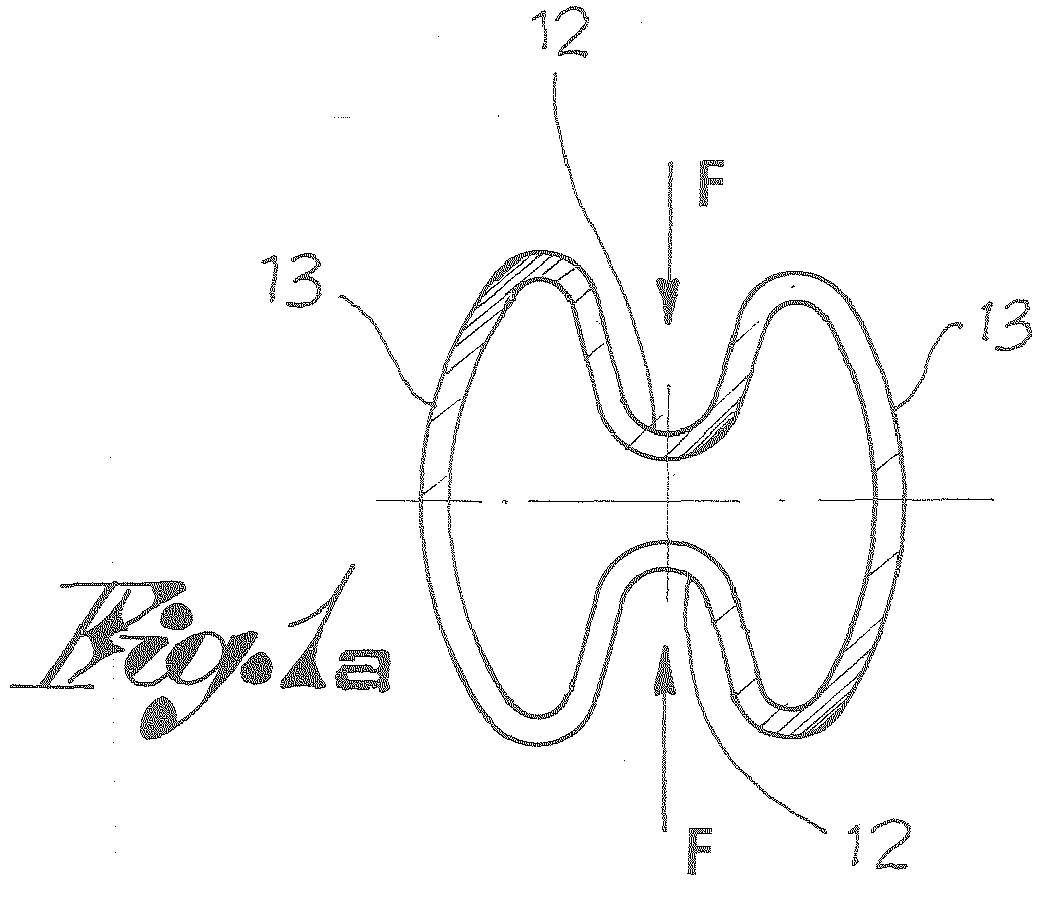
- Further features of the invention will appear more clearly from the following description, made with reference to the annexed indicative and non-limiting drawings, wherein:
- figures 1, 1a and 1b schematically show the method for flattening a portion of a tubular element;
- figure 2 shows a front view of the flattened end of a tubular element;
- figure 3 shows the same flattened end in a side view;
- figure 4 shows a front view of another example of the flattened end of a tubular element;
- figure 5 shows a perspective of a bending support of a sunbed having the ends flattened by the method of the invention.
- With reference to figures 1-1b, reference numeral 10 denotes a plan view of a portion of a
tubular element 11, for example with circular section, that must be flattened. - The
tubular element 11, for example, could be intended for obtaining a bending support for a sunbed, as shown in figure 5. - The method of the present invention provides for the radial deformation of said portion 10 of the
tubular element 11 by applying two opposed and converging radial forces F on two diametrically opposedlongitudinal portions 12 of portion 10. - Such deformation must be carried out in such way as to cause an approach of said two
longitudinal portions 12, leaving the remainingopposed parts 13 of portion 10 substantially non-deformed. - In other words, forces F must be preferably applied on very narrow
longitudinal portions 12, tending to a line. - Preferably, moreover, forces F must be such as to push the
longitudinal portions 12 inwards until they touch each other at the level of the tubular element axis. - Once such radial deformation has been applied, portion 10 is squashed acting on the entire surface of the non-deformed
parts 13 with opposed and converging forces F', directed orthogonally relative to the radial forces F. - Advantageously, this squashing is such as to make the radially deformed
longitudinal portions 12 andparts 13 deformed by squashing parallel and adjacent. - The resulting flattened portion, denoted with
reference numeral 14, virtually along its entire cross section, exhibits a thickness substantially equal to four times the thickness of the tubular element, as is clear in particular in figure 1b. - The
flattened portion 14 can then be drilled and optionally cut so as to obtain the desired shape according to its use, as shown in the examples of figures 2, 3 and 4.
Claims (5)
- Method for flattening a portion (10) of a tubular element (11), characterised in that it comprises the following sequence of steps:radially deforming said portion (10) of tubular element (11) by applying two converging radial forces (F) on two opposed longitudinal portions (12) relative to the main axis of the tubular element, so as to cause an approach of said two longitudinal portions leaving the remaining opposed parts (13) of the portion to be flattened substantially non-deformed,squashing the portion of tubular element acting on the entire surface of said non-deformed parts (13) with opposed and converging forces (F'), directed orthogonally relative to the radial forces.
- Method according to claim 1, wherein the radial deformation of the first step is such as to cause the tangency of the two longitudinal portions (12) at the level of the axis of the tubular element.
- Method according to claim 1 or 2, wherein the squashing of the second step is such as to make the radially deformed longitudinal portions and the parts deformed by squashing parallel and adjacent.
- Tubular element, particularly but not exclusively for obtaining frames of folding sunbeds, deck chairs and similar items, comprising at least one flattened portion (14) for coupling with another element of the frame, characterised in that said flattened portion exhibits, along its entire cross section, a thickness substantially equal to four times the thickness of the tubular element.
- Tubular element according to claim 4, wherein said flattened portion (14) is obtained with the method according to any one of claims from 1 to 3.
Applications Claiming Priority (2)
| Application Number | Priority Date | Filing Date | Title |
|---|---|---|---|
| ITBS20040021 | 2004-02-20 | ||
| ITBS20040021 ITBS20040021A1 (en) | 2004-02-20 | 2004-02-20 | METHOD TO APPLY A PORTION OF A TUBULAR ELEMENT |
Publications (1)
| Publication Number | Publication Date |
|---|---|
| EP1566229A1 true EP1566229A1 (en) | 2005-08-24 |
Family
ID=34708511
Family Applications (1)
| Application Number | Title | Priority Date | Filing Date |
|---|---|---|---|
| EP05100742A Withdrawn EP1566229A1 (en) | 2004-02-20 | 2005-02-03 | Method for flattening a portion of a tubular element |
Country Status (2)
| Country | Link |
|---|---|
| EP (1) | EP1566229A1 (en) |
| IT (1) | ITBS20040021A1 (en) |
Cited By (3)
| Publication number | Priority date | Publication date | Assignee | Title |
|---|---|---|---|---|
| US8490987B2 (en) | 2008-09-25 | 2013-07-23 | Mitsubishi Steel Mfg. Co., Ltd. | Stabilizer bar |
| WO2019193099A1 (en) * | 2018-04-05 | 2019-10-10 | Hydro Extruded Solutions As | Strut and method of manufacturing a strut |
| WO2025196250A1 (en) * | 2024-03-22 | 2025-09-25 | Hydro Extruded Solutions As | Method and apparatus for forming a strut |
Citations (2)
| Publication number | Priority date | Publication date | Assignee | Title |
|---|---|---|---|---|
| GB121352A (en) * | 1917-12-14 | 1918-12-16 | Rudge Whitworth Ltd | A New or Improved Method of Trapping the Ends of Metal Tubes. |
| DE19857589A1 (en) * | 1997-12-15 | 1999-07-15 | Honsel Profilprodukte Gmbh | Car door impact absorption carrier manufacturing process |
-
2004
- 2004-02-20 IT ITBS20040021 patent/ITBS20040021A1/en unknown
-
2005
- 2005-02-03 EP EP05100742A patent/EP1566229A1/en not_active Withdrawn
Patent Citations (2)
| Publication number | Priority date | Publication date | Assignee | Title |
|---|---|---|---|---|
| GB121352A (en) * | 1917-12-14 | 1918-12-16 | Rudge Whitworth Ltd | A New or Improved Method of Trapping the Ends of Metal Tubes. |
| DE19857589A1 (en) * | 1997-12-15 | 1999-07-15 | Honsel Profilprodukte Gmbh | Car door impact absorption carrier manufacturing process |
Cited By (6)
| Publication number | Priority date | Publication date | Assignee | Title |
|---|---|---|---|---|
| US8490987B2 (en) | 2008-09-25 | 2013-07-23 | Mitsubishi Steel Mfg. Co., Ltd. | Stabilizer bar |
| WO2019193099A1 (en) * | 2018-04-05 | 2019-10-10 | Hydro Extruded Solutions As | Strut and method of manufacturing a strut |
| CN112074356A (en) * | 2018-04-05 | 2020-12-11 | 海德鲁挤压解决方案股份有限公司 | Support column and method for producing a support column |
| JP2021519695A (en) * | 2018-04-05 | 2021-08-12 | ヒドロ・エクストゥルーデッド・ソリューションズ・アーエスHydro Extruded Solutions As | Struts and methods of manufacturing struts |
| US11786955B2 (en) | 2018-04-05 | 2023-10-17 | Hydro Extruded Solutions As | Strut and method of manufacturing a strut |
| WO2025196250A1 (en) * | 2024-03-22 | 2025-09-25 | Hydro Extruded Solutions As | Method and apparatus for forming a strut |
Also Published As
| Publication number | Publication date |
|---|---|
| ITBS20040021A1 (en) | 2004-05-20 |
Similar Documents
| Publication | Publication Date | Title |
|---|---|---|
| US8147002B2 (en) | Bamboo chair and method of manufacturing the bamboo chair | |
| EP1136043A3 (en) | Stent | |
| DE10253633B4 (en) | supporting structure | |
| EP1266640A3 (en) | Intravascular stent device | |
| EP1095631A3 (en) | Stent | |
| EP1295570A3 (en) | Cold-molding process for loading a stent onto a stent delivery system | |
| WO2009080348A4 (en) | Method of manufacturing a member of a wheelchair frame, tool for use in such a method and wheelchair frame | |
| EP3826510B1 (en) | Pneumatic structure and associated production method | |
| AU715908B2 (en) | Aluminum mesh with interlaced hollow and solid ribs | |
| EP1440789A3 (en) | Method for the production of tyres | |
| DE60210364D1 (en) | Method for producing a high-pressure accumulator, in particular for a spacecraft, and high-pressure accumulator produced by the method | |
| CN206277981U (en) | Vehicles handrail and vehicles armrest | |
| EP1295955A4 (en) | TITANIUM ALLOY HAVING EXCELLENT DUCTILITY, FATIGUE RESISTANCE AND STIFFNESS AND METHOD FOR PRODUCING THE SAME | |
| US6983987B2 (en) | Tubular metallic simulated bamboo, method for manufacturing and articles fabricated therefrom | |
| US5186382A (en) | Method of making patio chairs with metal slats | |
| EP2057916B1 (en) | Inflatable furniture | |
| CN204140570U (en) | Frame joint structure | |
| US378412A (en) | John bubkhabdt | |
| EP1747734B1 (en) | A sitting apparatus comprising seat tensioning means | |
| EP1616749A3 (en) | Seat for automotive vehicles | |
| US8499602B2 (en) | Decorative hollow tubing for use in furniture manufacture and method for manufacturing | |
| CN218843521U (en) | Aluminum profile with high-strength support | |
| DE10351823B3 (en) | Chair has seat and back which are supported by pair of inverted U-shaped frames (which are parallel to each other and held apart by spacers, lower sections of frames forming feet | |
| US20040005426A1 (en) | Decorative hollow tubing for use in furniture manufacture and method for manufacturing | |
| Sullivan | Right Turn. |
Legal Events
| Date | Code | Title | Description |
|---|---|---|---|
| PUAI | Public reference made under article 153(3) epc to a published international application that has entered the european phase |
Free format text: ORIGINAL CODE: 0009012 |
|
| AK | Designated contracting states |
Kind code of ref document: A1 Designated state(s): AT BE BG CH CY CZ DE DK EE ES FI FR GB GR HU IE IS IT LI LT LU MC NL PL PT RO SE SI SK TR |
|
| AX | Request for extension of the european patent |
Extension state: AL BA HR LV MK YU |
|
| AKX | Designation fees paid | ||
| REG | Reference to a national code |
Ref country code: DE Ref legal event code: 8566 |
|
| STAA | Information on the status of an ep patent application or granted ep patent |
Free format text: STATUS: THE APPLICATION IS DEEMED TO BE WITHDRAWN |
|
| 18D | Application deemed to be withdrawn |
Effective date: 20060225 |