EP1566115B1 - Cosmetic brush - Google Patents
Cosmetic brush Download PDFInfo
- Publication number
- EP1566115B1 EP1566115B1 EP04006234A EP04006234A EP1566115B1 EP 1566115 B1 EP1566115 B1 EP 1566115B1 EP 04006234 A EP04006234 A EP 04006234A EP 04006234 A EP04006234 A EP 04006234A EP 1566115 B1 EP1566115 B1 EP 1566115B1
- Authority
- EP
- European Patent Office
- Prior art keywords
- cosmetics
- brush
- cap
- movable body
- spring
- Prior art date
- Legal status (The legal status is an assumption and is not a legal conclusion. Google has not performed a legal analysis and makes no representation as to the accuracy of the status listed.)
- Expired - Lifetime
Links
- 239000002537 cosmetic Substances 0.000 title claims description 66
- 239000000843 powder Substances 0.000 claims description 15
- 239000007788 liquid Substances 0.000 claims description 6
- 230000002093 peripheral effect Effects 0.000 description 5
- 238000010276 construction Methods 0.000 description 2
- 238000007599 discharging Methods 0.000 description 1
- 230000000694 effects Effects 0.000 description 1
- 238000001914 filtration Methods 0.000 description 1
- 239000012535 impurity Substances 0.000 description 1
- 238000000034 method Methods 0.000 description 1
- 238000000926 separation method Methods 0.000 description 1
Images


Classifications
-
- E—FIXED CONSTRUCTIONS
- E01—CONSTRUCTION OF ROADS, RAILWAYS, OR BRIDGES
- E01C—CONSTRUCTION OF, OR SURFACES FOR, ROADS, SPORTS GROUNDS, OR THE LIKE; MACHINES OR AUXILIARY TOOLS FOR CONSTRUCTION OR REPAIR
- E01C9/00—Special pavings; Pavings for special parts of roads or airfields
- E01C9/004—Pavings specially adapted for allowing vegetation
-
- A—HUMAN NECESSITIES
- A46—BRUSHWARE
- A46B—BRUSHES
- A46B17/00—Accessories for brushes
- A46B17/04—Protective covers for the bristles
-
- A—HUMAN NECESSITIES
- A01—AGRICULTURE; FORESTRY; ANIMAL HUSBANDRY; HUNTING; TRAPPING; FISHING
- A01G—HORTICULTURE; CULTIVATION OF VEGETABLES, FLOWERS, RICE, FRUIT, VINES, HOPS OR SEAWEED; FORESTRY; WATERING
- A01G13/00—Protection of plants
- A01G13/20—Protective coverings for plants
- A01G13/27—Protective coverings for plants protecting specific parts of plants, e.g. roots, trunks or fruits
-
- A—HUMAN NECESSITIES
- A01—AGRICULTURE; FORESTRY; ANIMAL HUSBANDRY; HUNTING; TRAPPING; FISHING
- A01G—HORTICULTURE; CULTIVATION OF VEGETABLES, FLOWERS, RICE, FRUIT, VINES, HOPS OR SEAWEED; FORESTRY; WATERING
- A01G13/00—Protection of plants
- A01G13/30—Ground coverings
- A01G13/32—Mats; Nets; Sheets or films
-
- A—HUMAN NECESSITIES
- A01—AGRICULTURE; FORESTRY; ANIMAL HUSBANDRY; HUNTING; TRAPPING; FISHING
- A01G—HORTICULTURE; CULTIVATION OF VEGETABLES, FLOWERS, RICE, FRUIT, VINES, HOPS OR SEAWEED; FORESTRY; WATERING
- A01G20/00—Cultivation of turf, lawn or the like; Apparatus or methods therefor
-
- A—HUMAN NECESSITIES
- A01—AGRICULTURE; FORESTRY; ANIMAL HUSBANDRY; HUNTING; TRAPPING; FISHING
- A01G—HORTICULTURE; CULTIVATION OF VEGETABLES, FLOWERS, RICE, FRUIT, VINES, HOPS OR SEAWEED; FORESTRY; WATERING
- A01G20/00—Cultivation of turf, lawn or the like; Apparatus or methods therefor
- A01G20/20—Cultivation on mats
-
- A—HUMAN NECESSITIES
- A46—BRUSHWARE
- A46B—BRUSHES
- A46B11/00—Brushes with reservoir or other means for applying substances, e.g. paints, pastes, water
- A46B11/001—Brushes with reservoir or other means for applying substances, e.g. paints, pastes, water with integral reservoirs
- A46B11/002—Brushes with reservoir or other means for applying substances, e.g. paints, pastes, water with integral reservoirs pressurised at moment of use manually or by powered means
- A46B11/0055—Brushes with reservoir or other means for applying substances, e.g. paints, pastes, water with integral reservoirs pressurised at moment of use manually or by powered means with a reciprocating piston or plunger acting as the pressurising means
-
- A—HUMAN NECESSITIES
- A46—BRUSHWARE
- A46B—BRUSHES
- A46B7/00—Bristle carriers arranged in the brush body
- A46B7/02—Bristle carriers arranged in the brush body in an expanding or articulating manner
- A46B7/023—Bristle carriers arranged in the brush body in an expanding or articulating manner where the bristle carrier retracts or collapses, i.e. for storage
-
- A—HUMAN NECESSITIES
- A46—BRUSHWARE
- A46B—BRUSHES
- A46B2200/00—Brushes characterized by their functions, uses or applications
- A46B2200/10—For human or animal care
- A46B2200/1046—Brush used for applying cosmetics
Definitions
- the present invention relates to a cosmetics brush, more particularly, a cosmetics brush including a sleeve type protection cap for protection of the brush during make-up, a main body and a brush member.
- liquid cosmetics In general, cosmetics are divided into powdery and/or liquid states. Recently, the cosmetic goods such as lip-stick or foundation are available in the liquid state to improve convenience for users.
- the liquid cosmetics for example, is charged within a specified container generally having a pencil form and discharged out of an inner space of the container to an upper portion mounted by a cosmetic brush member of the container, when turning any portion of the container.
- Various forms and structures of such container have been proposed and used.
- Conventional cosmetics brush which is generally constructed by integrating a brush member to a main body of the brush and is used by covering the brush member with alternative cosmetics when doing the make-up has an inconvenience to carry and handle it due to the separation of the cosmetics and the brush member, to cause a difficulty in using the brush.
- Such cosmetics brush includes a first body 102 in a tube form having openings at top and bottom ends to receive powdery cosmetics 103 inside; a second body 106 coupled to the lower peripheral side of the first body 102, having an exhaust nozzle 107 on a middle portion of the top side and a brush member 108 connected to the exhaust nozzle 107; an upward/downward delivery shaft 109 connected to a spring 110 at a peripheral side of a front end thereof leading the front end to be coupled with the exhaust nozzle 107 of the second body 106, the spring 110 being mounted on and supported by a peripheral side of the top end of the exhaust nozzle 107; and a top side cap 113 for the protruding top end of the upward/downward delivery shaft 109 outside of the upper portion of the brush and for supporting the top end.
- the user pushes a button at the first body 102 joined to the top end of the upward/downward delivery shaft 109 and protruded upward when employing the cosmetics brush 100 to do the make-up.
- the spring 110 provided at the front end of such upward/downward delivery shaft 109 moves the shaft 109 in upward or downward directions so that the movement of the shaft 109 makes the powdery cosmetics 103 received inside the first body 102 to flow out to the external side, that is, to the brush member 108 through the exhaust nozzle 107 formed in the second body 106, to achieve a convenient use of the cosmetic brush.
- the powdery cosmetics 103 discharged through such exhaust nozzle 107 is supplied to the brush member 108 by directly passing the front end of the upward/downward delivery shaft 109.
- buttons 112 formed at the top side cap 113 which has a specified structure of being always protruded outside by the elastic force of the spring 110, has a disadvantage that the button 112 moves and causes undesirable exhaust of the powdery cosmetics 103 to the brush member 18 if the cosmetics brush is bumped against other items under carrying and holding conditions or is under external force.
- the powdery cosmetics 103 contained in the first body 102 and the one remained in the exhaust nozzle 103 are hardened owing to moisture.
- the known cosmetics brush in prior art cannot smoothly exhaust the powdery cosmetics 103.
- CH-538 829 A discloses a similar cosmetics brush according to the preamble of claim 1.
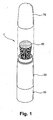
- Fig. 1 illustrates a perspective view of an example of the cosmetics brush according to the present invention.
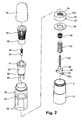
- Fig. 2 illustrates an exploded perspective view of the example of the cosmetics brush of Fig. 1 .
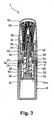
- Fig. 3 shows a cross-sectional view illustrating the cosmetics brush according to Fig. 1 in a state that the sleeve type protection cap is directed downward during holding and carrying the brush.
- Fig. 4 shows a cross-sectional view illustrating the cosmetics brush according to Fig. 1 in a state that the sleeve type protection cap is pulled outside.
- the cosmetics brush 1 of the present invention includes a main body 10 to receive powdery and/or liquid cosmetics (hereinafter, referring to as 'powder'), and a sleeve type protection cap 20 coupled to a top portion of the body 10 for enclosing a brush member 60 to protect it.
- 'powder' powdery and/or liquid cosmetics
- the protection cap 20 comprises an inner supporting wheel 22 having cylindrical supporting bars 32 elongated to both bottom sides of the wheel.
- the inner supporting wheel of such constructed protection cap 20 is connected to a fixture cap 27 and an O-ring 26 fitted on the supporting bar 32.
- the fixture cap 27 has a cross-section in form of a bottle cap having a punctured hole 27a on a center portion thereof, a screw portion 5a being formed over both inner sides of the fixture cap 27 and the punctured hole 27a.
- An inner movable body 40 having a bridge shape and comprising a guidance piece 42 is fitted inside the upper portion of the protection cap 20.
- Another screw portion 5b formed on a lower portion of the protection cap 20 is screw-coupled to the screw portion 5a formed inside the punctured hole 27a in the fixture cap 27.
- the protection cap 20, the inner movable body 40 and the fixture cap 27 are together integrated into an assembly, which also comprises a filter 46, an O-ring 26, a spring 54 and a movable body 50.
- the filter 46 is fitted into the inner movable body 40 while the O-ring 26 is fitted into the bottom portion of the fixture cap 27.
- the movable body 50 has a moving bar 52 with the spring 54 around and passing through a powder exhaust duct 41 of the inner movable body 40. On the top end of the moving bar 52 punctured through the duct 41, a push-cap 57 having an assisting brush 56 is fixed and connected.
- Such movable body 50 is positioned within the guidance piece 42 protruded on a bottom portion of the inner movable body 40, so that when the movable body 50 moves upward/downward, it can conduct perpendicular motion along the guidance piece 42.
- the bottom end of the supporting bar 32 is inserted and fixed into a fitting hole 51a of the movable body 50 to form a gap spaced between the movable body 50 and the sleeve type protection cap 20 by a constant interval.
- Such O-ring 26 and a guidance hole 24 of the fixture cap 27 are packed onto the supporting bars 32.
- the spring 54 is placed and extended between the inner movable body 40 and the movable body 50 as a typically initial condition of the cosmetics brush.
- a brush member 60 bundled by a clip 62 is fixed around the powder exhaust duct 41.
- An assembly formed by the brush 60 fixed around the powder exhaust duct 41 is connected at a lower portion thereof with the main body 10 charged with the powder by means of screw-connection manner while covering the top portion of the brush member 60 with a cover 70, thereby resulting in the final cosmetics brush assembly 1 as an example of the present invention.
- Such main body 10 has a screw member 5 coupled with the screw portion 5a of the fixture cap 27.
- the cosmetics brush 1 receives the powder and has the protection cap 27 and the movable body 50 going down by the elastic force of the spring 54 to close the exhaust nozzle 45 formed on the lower portion of the power exhaust duct 41 when it is normally held and/or carried.
- the user should grip the main body 10 by one hand, while pulling out the protection cap 20 and forcing the movable body 50 integrated with the protection cap 20 by means of the supporting bar 32 to slide upward along the guidance piece 42 formed on lower portion of the inner movable body 40. This applies a pressure to the inside of the inner movable body 40.
- the powder in the main body 10 flows to and passes the vertical holes 53 formed around a peripheral side of the movable bar 52, the exhaust nozzle 45 and the powder exhaust duct 41 in this order, as shown in Fig. 4 .
- the passed powder flows to and is exhausted to the assistant brush 56 and the brush 60 in a constant amount suitable to do the make-up.
- the powder discharged out of the powder exhaust duct 41 passes through a filter 46 formed in the lower portion of the inner movable body 40 to remove impurities or agglomerates before the exhausting process, so that only fine powders can flow into the powder exhaust duct 41.
- the protection cap 20 and the movable body 50 go down together and return to their original positions by the elastic force of the spring 54 located between the inner movable body 40 and the movable body 50.
- the repetition of pulling and releasing the protection cap 20 induces the powdery cosmetics charged inside the main body 10 to be exhausted to the assisting brush 56 and the brush member 60 and allows the user to do the make-up.
Landscapes
- Life Sciences & Earth Sciences (AREA)
- Environmental Sciences (AREA)
- Health & Medical Sciences (AREA)
- General Health & Medical Sciences (AREA)
- Toxicology (AREA)
- Engineering & Computer Science (AREA)
- Architecture (AREA)
- Civil Engineering (AREA)
- Structural Engineering (AREA)
- Brushes (AREA)
Description
- The present invention relates to a cosmetics brush, more particularly, a cosmetics brush including a sleeve type protection cap for protection of the brush during make-up, a main body and a brush member.
- In general, cosmetics are divided into powdery and/or liquid states. Recently, the cosmetic goods such as lip-stick or foundation are available in the liquid state to improve convenience for users. The liquid cosmetics, for example, is charged within a specified container generally having a pencil form and discharged out of an inner space of the container to an upper portion mounted by a cosmetic brush member of the container, when turning any portion of the container. Various forms and structures of such container have been proposed and used.
- Conventional cosmetics brush which is generally constructed by integrating a brush member to a main body of the brush and is used by covering the brush member with alternative cosmetics when doing the make-up has an inconvenience to carry and handle it due to the separation of the cosmetics and the brush member, to cause a difficulty in using the brush.
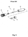
- In recent years, different structures of cosmetic brushes which receive powdery cosmetics inside a container type body and discharge the cosmetics to a brush member by air pressure suitable to do the make-up, have been proposed and applied, for example, the cosmetics brush disclosed in Korean Utility Model Reg. No. 253,672 having the construction as shown in
Figs. 5 and6 attached herein below. - Such cosmetics brush includes a
first body 102 in a tube form having openings at top and bottom ends to receivepowdery cosmetics 103 inside; asecond body 106 coupled to the lower peripheral side of thefirst body 102, having anexhaust nozzle 107 on a middle portion of the top side and abrush member 108 connected to theexhaust nozzle 107; an upward/downward delivery shaft 109 connected to aspring 110 at a peripheral side of a front end thereof leading the front end to be coupled with theexhaust nozzle 107 of thesecond body 106, thespring 110 being mounted on and supported by a peripheral side of the top end of theexhaust nozzle 107; and atop side cap 113 for the protruding top end of the upward/downward delivery shaft 109 outside of the upper portion of the brush and for supporting the top end. - In the above construction, the user pushes a button at the
first body 102 joined to the top end of the upward/downward delivery shaft 109 and protruded upward when employing thecosmetics brush 100 to do the make-up. At this time, thespring 110 provided at the front end of such upward/downward delivery shaft 109 moves theshaft 109 in upward or downward directions so that the movement of theshaft 109 makes thepowdery cosmetics 103 received inside thefirst body 102 to flow out to the external side, that is, to thebrush member 108 through theexhaust nozzle 107 formed in thesecond body 106, to achieve a convenient use of the cosmetic brush. - Herein, the
powdery cosmetics 103 discharged throughsuch exhaust nozzle 107 is supplied to thebrush member 108 by directly passing the front end of the upward/downward delivery shaft 109. - However, several problems exist in the conventional cosmetics brush as described above, for example, that since the
powdery cosmetics 103 flows out to thebrush member 108 by means of the front end of such upward/downward delivery shaft 109, the brush has not only a difficulty in constantly and continuously exhausting thepowdery cosmetics 103 due to constructional restriction of thedelivery shaft 109, but also a discomfort to use because thepowdery cosmetics 103 is discharging to thebrush member 108 by joggle of the cosmetics brush itself. - Further, another
button 112 formed at thetop side cap 113 which has a specified structure of being always protruded outside by the elastic force of thespring 110, has a disadvantage that thebutton 112 moves and causes undesirable exhaust of thepowdery cosmetics 103 to the brush member 18 if the cosmetics brush is bumped against other items under carrying and holding conditions or is under external force. In addition, when the cosmetics brush is stored and/or held in high humidity conditions, or is not employed for a long time, thepowdery cosmetics 103 contained in thefirst body 102 and the one remained in theexhaust nozzle 103 are hardened owing to moisture. Thus, the known cosmetics brush in prior art cannot smoothly exhaust thepowdery cosmetics 103. -
CH-538 829 A claim 1. - It is an object of the present invention to solve the above problems, in particular, to provide a cosmetics brush including a sleeve type protection cap mounted around a peripheral side of a brush member for protection of the cosmetics brush and a main body, wherein liquid or powdery cosmetics stored inside the main body is discharged to the brush member simultaneously with filtration of the cosmetics through a filter to ensure an optimum condition of preferably exhausting the cosmetics in a desirable amount.
- This object is solved by the features of
claim 1. - The above object, features and advantages of the present invention will become more apparent to those skilled in the art from the following detailed description of preferred embodiments taken in conjunction with the accompanying drawings, in which:
-
Fig. 1 is a perspective view illustrating an example of a cosmetics brush according to the present invention; -
Fig. 2 is an exploded perspective view illustrating the example of the cosmetics brush according toFig. 1 ; -
Fig. 3 is a cross-sectional view illustrating the cosmetics brush according toFig. 1 in a state that the sleeve type protection cap is directed downward during holding and carrying the brush; -
Fig. 4 is a cross-sectional view illustrating the cosmetics brush according toFig. 1 in a state that the sleeve type protection cap is pulled outside; -
Fig. 5 is a perspective view of a conventional cosmetics brush; and -
Fig. 6 is an exploded perspective view of the conventional cosmetics brush ofFig. 5 . - The present invention will be described in more detail with reference to the accompanying drawings which are presented for purpose of illustration and should not be construed to limit the scope of the invention.
-
Fig. 1 illustrates a perspective view of an example of the cosmetics brush according to the present invention.Fig. 2 illustrates an exploded perspective view of the example of the cosmetics brush ofFig. 1 .Fig. 3 shows a cross-sectional view illustrating the cosmetics brush according toFig. 1 in a state that the sleeve type protection cap is directed downward during holding and carrying the brush.Fig. 4 shows a cross-sectional view illustrating the cosmetics brush according toFig. 1 in a state that the sleeve type protection cap is pulled outside. - The
cosmetics brush 1 of the present invention includes amain body 10 to receive powdery and/or liquid cosmetics (hereinafter, referring to as 'powder'), and a sleevetype protection cap 20 coupled to a top portion of thebody 10 for enclosing abrush member 60 to protect it. - The
protection cap 20 comprises an inner supportingwheel 22 having cylindrical supportingbars 32 elongated to both bottom sides of the wheel. - The inner supporting wheel of such constructed
protection cap 20 is connected to afixture cap 27 and an O-ring 26 fitted on the supportingbar 32. - The
fixture cap 27 has a cross-section in form of a bottle cap having apunctured hole 27a on a center portion thereof, ascrew portion 5a being formed over both inner sides of thefixture cap 27 and thepunctured hole 27a. - An inner
movable body 40 having a bridge shape and comprising aguidance piece 42 is fitted inside the upper portion of theprotection cap 20. Anotherscrew portion 5b formed on a lower portion of theprotection cap 20 is screw-coupled to thescrew portion 5a formed inside thepunctured hole 27a in thefixture cap 27. - The
protection cap 20, the innermovable body 40 and thefixture cap 27 are together integrated into an assembly, which also comprises afilter 46, an O-ring 26, aspring 54 and amovable body 50. Thefilter 46 is fitted into the innermovable body 40 while the O-ring 26 is fitted into the bottom portion of thefixture cap 27. Themovable body 50 has a movingbar 52 with thespring 54 around and passing through apowder exhaust duct 41 of the innermovable body 40. On the top end of the movingbar 52 punctured through theduct 41, a push-cap 57 having an assistingbrush 56 is fixed and connected. - Such
movable body 50 is positioned within theguidance piece 42 protruded on a bottom portion of the innermovable body 40, so that when themovable body 50 moves upward/downward, it can conduct perpendicular motion along theguidance piece 42. Around the movingbar 52, severalvertical holes 53 are punctured in top and bottom directions to pass the powder. - Moreover, the bottom end of the supporting
bar 32 is inserted and fixed into afitting hole 51a of themovable body 50 to form a gap spaced between themovable body 50 and the sleevetype protection cap 20 by a constant interval. Such O-ring 26 and aguidance hole 24 of thefixture cap 27 are packed onto the supportingbars 32. Thespring 54 is placed and extended between the innermovable body 40 and themovable body 50 as a typically initial condition of the cosmetics brush. - A
brush member 60 bundled by aclip 62 is fixed around thepowder exhaust duct 41. - An assembly formed by the
brush 60 fixed around thepowder exhaust duct 41 is connected at a lower portion thereof with themain body 10 charged with the powder by means of screw-connection manner while covering the top portion of thebrush member 60 with acover 70, thereby resulting in the finalcosmetics brush assembly 1 as an example of the present invention. - Such
main body 10 has ascrew member 5 coupled with thescrew portion 5a of thefixture cap 27. - Based on the above structure of the cosmetics brush according to the present invention, the functional effect of the cosmetics brush will be described in more detail as follows.
- As shown in
Fig. 3 , thecosmetics brush 1 according to the present invention receives the powder and has theprotection cap 27 and themovable body 50 going down by the elastic force of thespring 54 to close theexhaust nozzle 45 formed on the lower portion of thepower exhaust duct 41 when it is normally held and/or carried. In order to do the make-up with the above state of the cosmetics brush, the user should grip themain body 10 by one hand, while pulling out theprotection cap 20 and forcing themovable body 50 integrated with theprotection cap 20 by means of the supportingbar 32 to slide upward along theguidance piece 42 formed on lower portion of the innermovable body 40. This applies a pressure to the inside of the innermovable body 40. As a result, the powder in themain body 10 flows to and passes thevertical holes 53 formed around a peripheral side of themovable bar 52, theexhaust nozzle 45 and thepowder exhaust duct 41 in this order, as shown inFig. 4 . The passed powder flows to and is exhausted to theassistant brush 56 and thebrush 60 in a constant amount suitable to do the make-up. - Furthermore, the powder discharged out of the
powder exhaust duct 41 passes through afilter 46 formed in the lower portion of the innermovable body 40 to remove impurities or agglomerates before the exhausting process, so that only fine powders can flow into thepowder exhaust duct 41. - Then, by releasing the pulling force applied to the sleeve
type protection cap 20, theprotection cap 20 and themovable body 50 go down together and return to their original positions by the elastic force of thespring 54 located between the innermovable body 40 and themovable body 50. - As described above, the repetition of pulling and releasing the
protection cap 20 induces the powdery cosmetics charged inside themain body 10 to be exhausted to the assistingbrush 56 and thebrush member 60 and allows the user to do the make-up. - Although figures attached herewith show the
brush member 60 as faced upward for a better illustration of the present invention, it is possible to easily exhaust the powdery cosmetics by directing thebrush member 60 downward and pulling theprotection cap 20, when the cosmetics brush is used.
Claims (2)
- A cosmetics brush including:at least one brush (56, 60),a main body (10) containing powdery or liquid cosmetics and covered by a fixture cap (27),an inner body (40) having a cosmetics exhaust duct (41);a sleeve-type protection cap (20);a movable body (50); anda spring (54) for preventing flow of cosmetics at a normal condition by pushing the movable body (50) in a predetermined direction;wherein the movable body (50) is movable against the force of the spring (54) in order to ensure that the cosmetics contained in the main body (10) are supplied to the at least one brush (56, 60);characterized in thatthe inner body (40) is connected to the fixture cap (27) such that the inner body (40) and the main body (10) are integrated into an assembly by means of the fixture cap (27);the fixture cap (27) has two guidance holes (24);the protection cap (20) has an inner supporting wheel (22) having two supporting bars (32) on a lower portion thereof, the supporting bars (32) extending through the guidance holes (24) in the fixture cap (27);the movable body (50) is fixed to the supporting bars (32), the movable body (50) and the protection cap (20) thus being integrated into an assembly and moving together;the spring is mounted between the inner body (40) and the movable body (50); andthe movable body (50) is movable in a direction towards the inner body (40) against the force of the spring (54) in order to generate air pressure to ensure that the cosmetics contained in the main body (10) are supplied to the at least one brush (56, 60).
- The cosmetics brush according to Claim 1, wherein it further includes a moving bar (52) having vertical holes (53) for delivering powdery cosmetic on top portion of the movable body (50) extended and fitted into the powder exhaust duct (41), and a push-cap (57) having an assisting brush (56) fitted at top end of the moving bar (52).
Applications Claiming Priority (2)
| Application Number | Priority Date | Filing Date | Title |
|---|---|---|---|
| KR2004011020 | 2004-02-19 | ||
| KR10-2004-0011020A KR100522307B1 (en) | 2004-02-19 | 2004-02-19 | Cosmetics brush |
Publications (2)
| Publication Number | Publication Date |
|---|---|
| EP1566115A1 EP1566115A1 (en) | 2005-08-24 |
| EP1566115B1 true EP1566115B1 (en) | 2008-10-22 |
Family
ID=34709350
Family Applications (1)
| Application Number | Title | Priority Date | Filing Date |
|---|---|---|---|
| EP04006234A Expired - Lifetime EP1566115B1 (en) | 2004-02-19 | 2004-03-16 | Cosmetic brush |
Country Status (4)
| Country | Link |
|---|---|
| US (1) | US6935802B1 (en) |
| EP (1) | EP1566115B1 (en) |
| KR (1) | KR100522307B1 (en) |
| DE (1) | DE602004017272D1 (en) |
Families Citing this family (51)
| Publication number | Priority date | Publication date | Assignee | Title |
|---|---|---|---|---|
| EP2290073A3 (en) | 2004-05-28 | 2011-08-31 | Asuragen, Inc. | Methods and compositions involving microRNA |
| CA2857878A1 (en) * | 2004-11-12 | 2006-12-28 | Asuragen, Inc. | Methods and compositions involving mirna and mirna inhibitor molecules |
| US7101107B1 (en) * | 2005-04-29 | 2006-09-05 | Young Kwang Byun | Cosmetics brush |
| KR100757511B1 (en) * | 2005-08-12 | 2007-09-11 | 변영광 | Cosmetic Case for Powder Discharge |
| KR100757508B1 (en) * | 2005-08-12 | 2007-09-11 | 변영광 | Cosmetic brush |
| EP1832197B1 (en) * | 2006-03-07 | 2009-04-15 | Young Kwang Byun | Make-up case for discharging powder |
| KR100781975B1 (en) * | 2006-07-20 | 2007-12-06 | 변영광 | Structure of Cosmetic Solution Dispensing Tool of Cosmetic Container |
| KR100688328B1 (en) * | 2006-08-31 | 2007-03-02 | 김종출 | Cosmetic brush |
| CA2663878A1 (en) * | 2006-09-19 | 2008-03-27 | Asuragen, Inc. | Mir-200 regulated genes and pathways as targets for therapeutic intervention |
| KR100733002B1 (en) * | 2006-09-28 | 2007-06-28 | 변영광 | Cosmetic Discharge Structure of Cosmetic Container |
| EP2104441A4 (en) | 2007-01-15 | 2013-09-18 | Young Kwang Byun | A discharge structure of the cosmetic brush |
| USD572010S1 (en) | 2007-08-03 | 2008-07-01 | Riaz Claudio S | Cosmetic brush |
| US7419323B1 (en) * | 2007-08-03 | 2008-09-02 | Chuen Chern Co., Ltd. | Cosmetic device |
| USD571559S1 (en) | 2007-08-07 | 2008-06-24 | Claudio S Riaz | Cosmetic brush |
| EP2198050A1 (en) | 2007-09-14 | 2010-06-23 | Asuragen, INC. | Micrornas differentially expressed in cervical cancer and uses thereof |
| USD585599S1 (en) | 2007-09-18 | 2009-01-27 | The Procter & Gamble Co. | Cosmetic container |
| KR200446793Y1 (en) * | 2008-02-04 | 2009-12-03 | 치아-쉥 창 | Quantitative Release Structure for Brushed Cosmetic Containers |
| USD588751S1 (en) | 2008-02-28 | 2009-03-17 | The Procter & Gamble Company | Cosmetic container |
| US8258111B2 (en) | 2008-05-08 | 2012-09-04 | The Johns Hopkins University | Compositions and methods related to miRNA modulation of neovascularization or angiogenesis |
| US8047214B2 (en) | 2008-07-11 | 2011-11-01 | Hct Asia Ltd | Powder puff dispenser with flow-through gasket |
| US8550738B2 (en) * | 2008-08-28 | 2013-10-08 | Hct Asia Ltd | Flow-through dispenser with helical actuation |
| USD625522S1 (en) | 2008-09-22 | 2010-10-19 | Riaz Claudio S | Cosmetic brush |
| US20100119287A1 (en) * | 2008-11-07 | 2010-05-13 | Hct Asia, Ltd. | Dispenser with a flow-through compressible gasket |
| US20100139677A1 (en) * | 2008-12-08 | 2010-06-10 | Yi-Li Tsai | Container for nail polish |
| US8534948B2 (en) * | 2009-03-06 | 2013-09-17 | Hct Asia Ltd | Dispenser with a cam path |
| US8177452B2 (en) * | 2009-04-08 | 2012-05-15 | Yi Li Tsai | Nail polish container |
| US8079771B2 (en) * | 2009-07-29 | 2011-12-20 | Chuan-Wei Ko | Spray brush |
| US20120227759A1 (en) * | 2011-03-07 | 2012-09-13 | Misty Hoffman | Combination of make-up dispenser and brush |
| WO2013040251A2 (en) | 2011-09-13 | 2013-03-21 | Asurgen, Inc. | Methods and compositions involving mir-135b for distinguishing pancreatic cancer from benign pancreatic disease |
| KR101313743B1 (en) | 2011-11-15 | 2013-10-01 | 변영광 | Powder cosmetic brush |
| KR200473413Y1 (en) | 2012-10-16 | 2014-08-06 | 주학로 | Tube typed cosmetic container having a emission control system |
| KR200475707Y1 (en) * | 2014-04-04 | 2014-12-24 | 주식회사 리오엘리 | A Cartridge Type Dyeing Brush |
| US10045600B2 (en) | 2014-09-18 | 2018-08-14 | HCT Group Holdings Limited | Container with quick release base and lid assembly |
| CA2974115A1 (en) | 2015-01-28 | 2016-08-04 | Neomed, Inc. | Cleaning device and method for fluid transfer connector |
| US11045278B2 (en) | 2015-01-28 | 2021-06-29 | Neomed, Inc. | Cleaning device and method for using the same |
| US9993059B2 (en) | 2015-07-10 | 2018-06-12 | HCT Group Holdings Limited | Roller applicator |
| USD786088S1 (en) | 2015-07-10 | 2017-05-09 | HCT Group Holdings Limited | Angled pump with depression |
| USD856814S1 (en) | 2015-07-10 | 2019-08-20 | HCT Group Holdings Limited | Combined cosmetics dispenser and applicator |
| USD784162S1 (en) | 2015-10-08 | 2017-04-18 | HCT Group Holdings Limited | Tottle |
| USD842565S1 (en) | 2016-01-28 | 2019-03-05 | Neomed, Inc. | Cleaning device for enteral fluid couplings |
| USD818641S1 (en) | 2016-03-16 | 2018-05-22 | HCT Group Holdings Limited | Cosmetics applicator with cap |
| CN108308836B (en) * | 2017-01-18 | 2024-04-12 | 怀化学院 | Broom |
| USD884481S1 (en) | 2017-01-19 | 2020-05-19 | HCT Group Holdings Limited | Combined cosmetics dispenser and applicator |
| US10531722B2 (en) | 2017-02-16 | 2020-01-14 | Hct Packaging, Inc. | Adjustable applicator |
| KR101895714B1 (en) * | 2017-04-11 | 2018-09-05 | 이민영 | For cosmetics brush case |
| USD833156S1 (en) | 2017-07-06 | 2018-11-13 | HCT Group Holdings Limited | Cosmetics brush with rectangular ferrule |
| USD876102S1 (en) | 2018-03-01 | 2020-02-25 | HCT Group Holdings Limited | Twisted conical brush handle |
| USD880872S1 (en) | 2018-03-14 | 2020-04-14 | HCT Group Holdings Limited | Tapered brush handle |
| US10966513B2 (en) | 2018-03-15 | 2021-04-06 | HCT Group Holdings Limited | Synthetic goat hair brush |
| US11957238B1 (en) * | 2019-08-27 | 2024-04-16 | Colorescience, Inc. | Sunscreen dispensing brush and methods of using same |
| KR102396067B1 (en) | 2020-05-08 | 2022-05-11 | 지에스피트레이딩 주식회사 | Eco-friendly brush |
Family Cites Families (12)
| Publication number | Priority date | Publication date | Assignee | Title |
|---|---|---|---|---|
| US1044996A (en) * | 1909-09-07 | 1912-11-19 | William Cuthbertson | Brush. |
| CH538829A (en) * | 1971-06-07 | 1973-07-15 | Ritter Gustav | Foam dispenser |
| US4548524A (en) * | 1982-07-22 | 1985-10-22 | Calumet Manufacturing Co. | Dispensing package with applicator surface |
| NL8700697A (en) * | 1987-03-25 | 1988-10-17 | Multigood Bv | BRUSH. |
| KR200165482Y1 (en) * | 1998-12-15 | 2000-02-15 | 변영광 | Cosmetic brush |
| US6234181B1 (en) * | 2000-01-06 | 2001-05-22 | Jia Hsing Enterprises Co., Ltd. | Rouge powder brush structure |
| EP1125519A1 (en) * | 2000-01-20 | 2001-08-22 | Young Kwang Byun | Cosmetic Brush |
| KR200190860Y1 (en) * | 2000-01-21 | 2000-08-01 | 주식회사에프에스코리아 | Brush having powder box |
| KR200224628Y1 (en) * | 2000-10-07 | 2001-05-15 | 변영광 | Cosmetic brush |
| KR200277197Y1 (en) * | 2001-12-14 | 2002-06-03 | 변영광 | cosmetic implement having improved injecting structure |
| US6752558B1 (en) * | 2003-03-26 | 2004-06-22 | Kuo Sung Hsu | Liquid lipstick dispensing device |
| US6688796B1 (en) * | 2003-04-11 | 2004-02-10 | Ming Hsiung Liu | Brush for make-up |
-
2004
- 2004-02-19 KR KR10-2004-0011020A patent/KR100522307B1/en not_active Expired - Lifetime
- 2004-03-09 US US10/795,293 patent/US6935802B1/en not_active Expired - Lifetime
- 2004-03-16 EP EP04006234A patent/EP1566115B1/en not_active Expired - Lifetime
- 2004-03-16 DE DE602004017272T patent/DE602004017272D1/en not_active Expired - Lifetime
Also Published As
| Publication number | Publication date |
|---|---|
| US6935802B1 (en) | 2005-08-30 |
| KR20050082547A (en) | 2005-08-24 |
| US20050186018A1 (en) | 2005-08-25 |
| DE602004017272D1 (en) | 2008-12-04 |
| EP1566115A1 (en) | 2005-08-24 |
| KR100522307B1 (en) | 2005-10-19 |
Similar Documents
| Publication | Publication Date | Title |
|---|---|---|
| US6935802B1 (en) | Cosmetics brush | |
| US7234474B2 (en) | Cosmetics brush | |
| US5269062A (en) | Folding razor with a foam dispenser | |
| ES2230180T3 (en) | MANUAL PRODUCT DISPENSERS WITH PRESSURE DOWNLOAD. | |
| US4289153A (en) | Hair styling device | |
| US5322382A (en) | Combination lotion applicator and stand | |
| US3960160A (en) | Hair treatment appliance | |
| US5391011A (en) | Applicator for makeup or for a hair-care product | |
| EP0987189B1 (en) | Collapsible cap mechanism for shielding pump actuator and liquid material-dispensing container including the same | |
| KR200454099Y1 (en) | Push pocket structure of the dropper type cosmetic container | |
| JP2008509860A (en) | Liquid dispensing device | |
| US6659109B2 (en) | Powder puff device for a receptacle | |
| US6325564B1 (en) | Long handle lotion applicator | |
| JP2001516273A (en) | Improvement of liquid dispensing device and improvement on liquid dispensing device | |
| US5360142A (en) | Supply assembly for water propelling device | |
| JP2005517601A (en) | Squeeze spray device | |
| US8002001B2 (en) | Refilling device and method of filling | |
| JPH0634852Y2 (en) | The head of the acupressure container | |
| KR200487397Y1 (en) | Cosmetic container | |
| US20090026103A1 (en) | Consumption Tracker for a Fluid Container | |
| KR102111364B1 (en) | Hair brush for hair styling | |
| KR200216091Y1 (en) | An aromatic container | |
| JPH0632204Y2 (en) | Nozzle for injection device | |
| US20070257125A1 (en) | Spray Tanning Delivery Device | |
| KR100398269B1 (en) | Device for hair setting |
Legal Events
| Date | Code | Title | Description |
|---|---|---|---|
| PUAI | Public reference made under article 153(3) epc to a published international application that has entered the european phase |
Free format text: ORIGINAL CODE: 0009012 |
|
| AK | Designated contracting states |
Kind code of ref document: A1 Designated state(s): AT BE BG CH CY CZ DE DK EE ES FI FR GB GR HU IE IT LI LU MC NL PL PT RO SE SI SK TR |
|
| AX | Request for extension of the european patent |
Extension state: AL LT LV MK |
|
| AKX | Designation fees paid | ||
| 17P | Request for examination filed |
Effective date: 20060517 |
|
| RBV | Designated contracting states (corrected) |
Designated state(s): DE FR GB IT |
|
| 17Q | First examination report despatched |
Effective date: 20070319 |
|
| GRAP | Despatch of communication of intention to grant a patent |
Free format text: ORIGINAL CODE: EPIDOSNIGR1 |
|
| GRAS | Grant fee paid |
Free format text: ORIGINAL CODE: EPIDOSNIGR3 |
|
| GRAA | (expected) grant |
Free format text: ORIGINAL CODE: 0009210 |
|
| AK | Designated contracting states |
Kind code of ref document: B1 Designated state(s): DE FR GB IT |
|
| REG | Reference to a national code |
Ref country code: GB Ref legal event code: FG4D |
|
| REF | Corresponds to: |
Ref document number: 602004017272 Country of ref document: DE Date of ref document: 20081204 Kind code of ref document: P |
|
| PLBE | No opposition filed within time limit |
Free format text: ORIGINAL CODE: 0009261 |
|
| STAA | Information on the status of an ep patent application or granted ep patent |
Free format text: STATUS: NO OPPOSITION FILED WITHIN TIME LIMIT |
|
| 26N | No opposition filed |
Effective date: 20090723 |
|
| REG | Reference to a national code |
Ref country code: DE Ref legal event code: R082 Ref document number: 602004017272 Country of ref document: DE Representative=s name: STOLMAR & PARTNER PATENTANWAELTE PARTG MBB, DE Ref country code: DE Ref legal event code: R081 Ref document number: 602004017272 Country of ref document: DE Owner name: BYUNG, YOUNG-KWANG, KR Free format text: FORMER OWNER: BYUN, YOUNG-CHUL, SEOUL, KR Ref country code: DE Ref legal event code: R081 Ref document number: 602004017272 Country of ref document: DE Owner name: BYUN, YOUNG-KWANG, KR Free format text: FORMER OWNER: BYUN, YOUNG-CHUL, SEOUL, KR Ref country code: DE Ref legal event code: R082 Ref document number: 602004017272 Country of ref document: DE Representative=s name: RATNER & PRESTIA, P.C., ZWEIGNIEDERLASSUNG MUE, DE |
|
| REG | Reference to a national code |
Ref country code: DE Ref legal event code: R082 Ref document number: 602004017272 Country of ref document: DE Representative=s name: STOLMAR & PARTNER PATENTANWAELTE PARTG MBB, DE Ref country code: DE Ref legal event code: R082 Ref document number: 602004017272 Country of ref document: DE Representative=s name: RATNER & PRESTIA, P.C., ZWEIGNIEDERLASSUNG MUE, DE |
|
| REG | Reference to a national code |
Ref country code: FR Ref legal event code: PLFP Year of fee payment: 13 |
|
| REG | Reference to a national code |
Ref country code: FR Ref legal event code: PLFP Year of fee payment: 14 |
|
| REG | Reference to a national code |
Ref country code: DE Ref legal event code: R082 Ref document number: 602004017272 Country of ref document: DE Representative=s name: SCHEELE JAEGER WETZEL PATENTANWAELTE PARTNERSC, DE Ref country code: DE Ref legal event code: R082 Ref document number: 602004017272 Country of ref document: DE Representative=s name: SCHEELE WETZEL PATENTANWAELTE, DE Ref country code: DE Ref legal event code: R082 Ref document number: 602004017272 Country of ref document: DE Representative=s name: SCHEELE WETZEL PATENTANWAELTE PARTNERSCHAFTSGE, DE Ref country code: DE Ref legal event code: R082 Ref document number: 602004017272 Country of ref document: DE Representative=s name: RATNER & PRESTIA, P.C., ZWEIGNIEDERLASSUNG MUE, DE |
|
| REG | Reference to a national code |
Ref country code: FR Ref legal event code: PLFP Year of fee payment: 15 |
|
| REG | Reference to a national code |
Ref country code: DE Ref legal event code: R082 Ref document number: 602004017272 Country of ref document: DE Representative=s name: SCHEELE JAEGER WETZEL PATENTANWAELTE PARTNERSC, DE Ref country code: DE Ref legal event code: R082 Ref document number: 602004017272 Country of ref document: DE Representative=s name: SCHEELE WETZEL PATENTANWAELTE, DE Ref country code: DE Ref legal event code: R082 Ref document number: 602004017272 Country of ref document: DE Representative=s name: SCHEELE WETZEL PATENTANWAELTE PARTNERSCHAFTSGE, DE |
|
| PGFP | Annual fee paid to national office [announced via postgrant information from national office to epo] |
Ref country code: FR Payment date: 20230328 Year of fee payment: 20 |
|
| PGFP | Annual fee paid to national office [announced via postgrant information from national office to epo] |
Ref country code: GB Payment date: 20230316 Year of fee payment: 20 Ref country code: DE Payment date: 20230321 Year of fee payment: 20 |
|
| PGFP | Annual fee paid to national office [announced via postgrant information from national office to epo] |
Ref country code: IT Payment date: 20230328 Year of fee payment: 20 |
|
| REG | Reference to a national code |
Ref country code: DE Ref legal event code: R071 Ref document number: 602004017272 Country of ref document: DE |
|
| REG | Reference to a national code |
Ref country code: GB Ref legal event code: PE20 Expiry date: 20240315 |
|
| PG25 | Lapsed in a contracting state [announced via postgrant information from national office to epo] |
Ref country code: GB Free format text: LAPSE BECAUSE OF EXPIRATION OF PROTECTION Effective date: 20240315 |