EP1565009A2 - Wall mount cabinet system - Google Patents

Wall mount cabinet system Download PDF

Info

Publication number
EP1565009A2
EP1565009A2 EP05250906A EP05250906A EP1565009A2 EP 1565009 A2 EP1565009 A2 EP 1565009A2 EP 05250906 A EP05250906 A EP 05250906A EP 05250906 A EP05250906 A EP 05250906A EP 1565009 A2 EP1565009 A2 EP 1565009A2
Authority
EP
European Patent Office
Prior art keywords
cabinet
wall mount
rear section
cutout area
section
Prior art date
Legal status (The legal status is an assumption and is not a legal conclusion. Google has not performed a legal analysis and makes no representation as to the accuracy of the status listed.)
Withdrawn
Application number
EP05250906A
Other languages
German (de)
French (fr)
Other versions
EP1565009A3 (en
Inventor
Jack E. Caveney
Samuel J. Adducci
Robert L. Fritz
Current Assignee (The listed assignees may be inaccurate. Google has not performed a legal analysis and makes no representation or warranty as to the accuracy of the list.)
Panduit Corp
Original Assignee
Panduit Corp
Priority date (The priority date is an assumption and is not a legal conclusion. Google has not performed a legal analysis and makes no representation as to the accuracy of the date listed.)
Filing date
Publication date
Application filed by Panduit Corp filed Critical Panduit Corp
Publication of EP1565009A2 publication Critical patent/EP1565009A2/en
Publication of EP1565009A3 publication Critical patent/EP1565009A3/en
Withdrawn legal-status Critical Current

Links

Images

Classifications

    • HELECTRICITY
    • H04ELECTRIC COMMUNICATION TECHNIQUE
    • H04QSELECTING
    • H04Q1/00Details of selecting apparatus or arrangements
    • H04Q1/02Constructional details
    • H04Q1/06Cable ducts or mountings specially adapted for exchange installations
    • H04Q1/062Cable ducts or mountings specially adapted for exchange installations vertical management arrangements
    • HELECTRICITY
    • H04ELECTRIC COMMUNICATION TECHNIQUE
    • H04QSELECTING
    • H04Q1/00Details of selecting apparatus or arrangements
    • H04Q1/02Constructional details
    • H04Q1/021Constructional details using pivoting mechanisms for accessing the interior of the apparatus
    • HELECTRICITY
    • H04ELECTRIC COMMUNICATION TECHNIQUE
    • H04QSELECTING
    • H04Q1/00Details of selecting apparatus or arrangements
    • H04Q1/02Constructional details
    • H04Q1/025Cabinets
    • HELECTRICITY
    • H04ELECTRIC COMMUNICATION TECHNIQUE
    • H04QSELECTING
    • H04Q1/00Details of selecting apparatus or arrangements
    • H04Q1/02Constructional details
    • H04Q1/035Cooling of active equipments, e.g. air ducts
    • HELECTRICITY
    • H04ELECTRIC COMMUNICATION TECHNIQUE
    • H04QSELECTING
    • H04Q1/00Details of selecting apparatus or arrangements
    • H04Q1/02Constructional details
    • H04Q1/06Cable ducts or mountings specially adapted for exchange installations
    • H04Q1/064Cable ducts or mountings specially adapted for exchange installations horizontal management arrangements
    • HELECTRICITY
    • H04ELECTRIC COMMUNICATION TECHNIQUE
    • H04QSELECTING
    • H04Q1/00Details of selecting apparatus or arrangements
    • H04Q1/02Constructional details
    • H04Q1/06Cable ducts or mountings specially adapted for exchange installations
    • H04Q1/066Cable ducts or mountings specially adapted for exchange installations arranged on the front side
    • HELECTRICITY
    • H04ELECTRIC COMMUNICATION TECHNIQUE
    • H04QSELECTING
    • H04Q2201/00Constructional details of selecting arrangements
    • H04Q2201/08Pivotable parts
    • HELECTRICITY
    • H04ELECTRIC COMMUNICATION TECHNIQUE
    • H04QSELECTING
    • H04Q2201/00Constructional details of selecting arrangements
    • H04Q2201/10Housing details

Definitions

  • the present invention is directed to a telecommunications enclosure, and more particularly, to a wall mount cabinet system.
  • Hinged wall mount cabinets have been utilized in the telecommunications industry. For example, Chatsworth Products, Inc.'s Cube-It PLUS TM Wall Mount Cabinet mounts a rear section of a cabinet to a wall for receiving cables therein. The cables are threaded through openings or knockouts in the top side of the rear section, and cables are secured to the inside surface of the rear section utilizing a tie or fastener. Slack cable is provided in the rear section to allow the cabinet to move from a closed to an open position, without damaging the cables. Hubbell Premise Wiring's QuadCab TM Hinged Wall Mount Cabinet functions similarly to Chatsworth's Cube-It PLUS TM wall mount cabinet.
  • none of the prior hinged wall mount cabinets provide a cutout area in the rear section of the cabinet and offer the ability to install cables without having to thread the cables through an opening or knockout. Moreover, none of the prior hinged wall mount cabinets allow cables passing vertically through the rear section to rotate about a pivot point where the front and rear sections of the cabinet connect, as the cabinet is moved from a closed to an open position.
  • hinged wall mount cabinets do not include slack cable managers secured therein.
  • Category 5 and 5E cables are provided in one foot minimum lengths.
  • slack cable management within the cabinet is not essential.
  • Category 6 cables are provided in three foot minimum lengths.
  • slack cable managers may be desired within a cabinet for internal management of Category 6 cables.
  • none of the prior hinged wall mount cabinets provide a slack cable manager secured within the cabinet.
  • the wall mount cabinet includes a rear section having a first end and a second end, and a front section hingedly connected to the rear section at a pivot point.
  • the rear section has a cutout area adjacent its first end, and the cutout area allows access for cables to enter the cabinet.
  • the pivot point is adjacent the cutout area and the first end of the rear section. The cutout area allows cables to rotate about the pivot point when the cabinet is moved from a closed to an open position.
  • the front section of the cabinet has a cable management ring secured thereon.
  • the cable management ring When the cabinet is in a closed position, the cable management ring is vertically aligned with the cutout area.
  • the cable management ring has a first arm and a second arm.
  • Each of the arms is substantially L-shaped and has a distal portion oriented substantially 90 degrees from a substantially linear portion.
  • Each arm is formed of a material and construction selected to provide rotation from a first 90 degree angle to a second 90 degree angle of the distal portion with respect to the proximate portion.
  • the cabinet includes a hinged duct or transition duct positioned adjacent the cutout area.
  • the cabinet includes two side access panels and a front door.
  • the front door may include a transparent window.
  • the cabinet includes a rod which maintains the front section in an open position about 90 degrees from the rear section.
  • the front section of the cabinet includes a slack cable manager, a patch panel, a horizontal cable manager or active equipment secured to a rail mounted therein.
  • FIG. 1 is a top front left perspective view of a wall mount cabinet system according to the present invention
  • FIG. 2 is a top front right perspective view of the wall mount cabinet system of FIG. 1;
  • FIG. 3 is a top front right perspective view of the wall mount cabinet system of FIG. 2, showing the right side access panel in an open position;
  • FIG. 4 is an enlarged view of the wall mount cabinet system of FIG. 1, showing the top panel removed and the front door and left and right side access panels in an open position;
  • FIG. 5 is an enlarged view of the wall mount cabinet system of FIG. 1, showing the top panel removed and the cabinet in an open position;
  • FIG. 6 is an enlarged view of the wall mount cabinet system of FIG. 2, with the top panel removed and the front door and cabinet in an open position;
  • FIG. 7 is an exploded view of the wall mount cabinet system of FIG. 2;
  • FIG. 8 is a cross-sectional view of the wall mount cabinet system taken along lines 8-8 of FIG. 2;
  • FIG. 9 is an enlarged view of the cable entrance area of FIG. 8;
  • FIG. 10 is an enlarged view of the wall mount cabinet system of FIG. 5;
  • FIG. 11 is a top view of the wall mount cabinet system of FIG. 10;
  • FTG. 12 is a top front left perspective view of the wall mount cabinet system of FIG. 4, showing cables and optional equipment installed therein;
  • FIG. 13 is a top front left perspective view of the wall mount cabinet system of FIG. 5, showing cables and optional equipment installed therein;
  • FIG. 14 is a top front left perspective view of the wall mount cabinet system of FIG. 1, showing the front door having a transparent window and conduit installed therein;
  • FIG. 15 is a top front right perspective view of the wall mount cabinet system of FIG. 2, showing a transition duct instead of a hinged duct; and
  • FIG. 16 is a top front left perspective view of the wall mount cabinet system of FIG. 12, showing the cabinet and transition duct in an open position.
  • FIGS. 1-14 show wall mount cabinet system 20 comprising a cabinet 22 mounted to a wall 24 and a hinged duct 26 for receiving cables 28 passing vertically therethrough.
  • hinged duct 26 allows access to cables 28 when cabinet 22 is in an open position.
  • transition duct 30 may be utilized instead of hinged duct 26. Transition duct 30 also allows access to cables 28 passing through conduit 32 when cabinet 22 is in an open position.
  • cabinet 22 includes a front section 34 and a rear section 36.
  • Front section 34 is hingedly connected to rear section 36 at a pivot point 38, shown in FIGS. 9 and 11, and rear section 36 is mounted to wall 24.
  • rear section 36 includes four keyholes 40 for mounting rear section 36 to wall 24.
  • rear section 36 is illustrated in FIGS. 1-16 mounted to wall 24, it is likewise contemplated that rear section 36 may be mounted to other structures, such as a 7/8 inch or 1 5/8 inch Unistrut® channel on a wall.
  • Rear section 36 has a top side 42, a bottom side 44, a left side 46 and a right side 48.
  • top side 42 includes three knockouts 50 for receiving 2 inch diameter conduit 52 (see FIG. 14), a knockout 54 for receiving a raceway section, and three knockouts 56 for receiving 2 inch or : inch diameter conduit 58 (see FIG. 14).
  • bottom side 44 includes three knockouts 60 for receiving 2 inch diameter conduit, a knockout 62 for receiving a raceway section, and three knockouts 64 for receiving 2 inch or : inch diameter conduit.
  • rear section 36 has a cutout area 66 at one end of top side 42 adjacent right side 48.
  • cutout area 66 When cabinet 22 is in a closed position, cutout area 66 is vertically aligned with hinged duct 26, as best seen in FIG. 12, to allow cables 28 to pass vertically therethrough into cabinet 22. Cutout area 66 allows cables 28 to be installed without having to thread cables 28 through an opening or a knockout.
  • pivot point 38 is located adjacent cutout area 66. The proximity of pivot point 38 to cutout area 66 minimizes movement of cables 28 when cabinet 22 is moved from the closed position to the open position, as cables 28 rotate about pivot point 38.
  • FIG. 13 when cabinet 22 is moved from the closed position to the open position, cables 28 are displaced within hinged duct 26 as cables 28 rotate about pivot point 38.
  • rod 67 is inserted into a slot in each of front section 34 and rear section 36.
  • Rod 67 maintains front section 34 in an open position about 90 degrees from rear section 36.
  • rod 67 may be sized and configured to maintain front section 34 in an open position at any angular orientation between 0 and about 100 degrees with respect to rear section 36. Without rod 67 in place, front section 34 has a tendency to move toward rear section 36 and, thus, make it difficult for a user to have uninterrupted access to cables 28.
  • rod 67 may be secured to the inside surface of rear section 36 utilizing a clip or other securement devices known in the art.
  • front section 34 of cabinet 22 includes a top panel 68, a front door 70, a left side access panel 72 and a right side access panel 74. Left side access panel 72 and right side access panel 74 are hingedly connected to cabinet 22. Similarly, front door 70 is hingedly connected to cabinet 22. Although front door 70 is shown in FIGS. 1-7 as solid, it is likewise contemplated that front door 70 may have a transparent window 76, as best seen in FIG. 14. Each of front door 70, left side access panel 72 and right side access panel 74 is provided with locks for security and are keyed alike. Similarly, front section 34 is provided with a lock for security and is keyed alike. [00037] As shown in FIG.
  • left side access panel 72 includes vent louvers 78 to optimize air flow and ventilation within cabinet 22.
  • right side access panel 74 includes vent louvers 80 to optimize air flow and ventilation within cabinet 22.
  • right side access panel 74 may include a fan assembly 82 secured therein.
  • left side access panel 72 may include fan assembly 82 secured therein.
  • front section 34 of cabinet 22 has two top rails 84, 86, each rail extending from near front door 70 to near rear section 36 of cabinet 22.
  • front section 34 includes two bottom rails 88, 90 extending from near front door 70 to near rear section 36 of cabinet 22.
  • bottom rails 88, 90 are vertically aligned with top rails 84, 86, respectively.
  • two vertical rails 92, 94 are mounted to top rails 84, 86 and bottom rails 88, 90, respectively, near front door 70.
  • Vertical rails 92, 94 are adjustable from front to rear in one inch increments.
  • vertical rails 92, 94 include marking indicia thereon.
  • a slack cable manager 96 is secured to top rail 84 and bottom rail 88, adjacent left side access panel 72. Slack cable manager 96 provides slack storage for multiple length patch cords and is adjustable from front to rear in one inch increments. Similarly, as best seen in FIGS. 3 and 8, a slack cable manager 98 is secured to top rail 86 and bottom rail 90, adjacent right side access panel 74. Slack cable manager 98 provides slack storage for multiple length patch cords and is adjustable from front to rear in one inch increments.
  • front section 34 of cabinet 22 includes three horizontal cable managers, such as cable manager 100 without a cover and cable manager 102 with a hinged cover. Further, front section 34 of cabinet 22 includes two patch panels 104. Each of horizontal cable managers 100, 102 and patch panels 104 is secured to vertical rails 92, 94. Moreover, front section 34 of cabinet 22 includes active equipment 106, such as a Cisco® catalyst switch or a Nortel® baystack, secured to vertical rails 92, 94. Vertical rails 92, 94 are adjustable from front to rear, even after installation of slack cable managers 96, 98, horizontal cable managers 100, 102, patch panels 104 or active equipment 106. Preferably, cabinet 22 is 24 inches in depth to accommodate typical active equipment.
  • S-hooks 108, 110 may be secured to slack cable managers 96, 98, respectively.
  • S-hooks 108, 110 manage cables within front section 34 of cabinet 22.
  • S-hook 108 is positioned adjacent left side access panel 72
  • S-hook 110 is positioned adjacent right side access panel 74.
  • a D-ring (not shown), such as the one disclosed in U.S. Patent No. 6,427,952, which is hereby incorporated by reference, may be utilized instead of S-hooks 108, 110.
  • front section 34 of cabinet 22 includes a flexible D-ring 112 secured to a back edge of front section 34.
  • D-ring 112 when cabinet 22 is in the closed position, D-ring 112 is vertically aligned with cutout area 66 in rear section 34 of cabinet 22. D-ring 112 may be rotatably flexed to an open position which allows access to the maximum extent of the opening, thus permitting easier access for the larger cables or bundles of cables.
  • D-ring 112 includes mounting holes 114 on baseplate 116 which secures D-ring 112 in a desired position on front section 34 of cabinet 22.
  • D-ring 112 is formed of a strong but flexible, resilient plastic material, to have significant resistance to the flexing.
  • D-ring 112 has a baseplate 116 including a first arm 118 and a second arm 120.
  • first arm 118 and second arm 120 are substantially L-shaped.
  • First arm 118 has a proximate portion 122 which extends in a generally linear fashion away from baseplate 116, and a distal portion 124 oriented substantially 90 degrees from proximate portion 122.
  • First arm 118 may be twisted or rotated in either direction (up or down) at least 90 degrees.
  • second arm 120 has a proximate portion 126 which extends in a generally perpendicular fashion away from baseplate 116, and a distal portion 128 oriented substantially 90 degrees from proximate portion 126.
  • Second arm 120 may be twisted or rotated in either direction (up or down) at least 90 degrees.
  • D-ring 112 provides access to cables 28 secured therein from two directions.
  • the twisting movement of first arm 118 and second arm 120 may be controlled by a desired cross-section and material selection. Consequently, a large number of cables, or large cables, may be expeditiously placed in or removed from D-ring 112 as a contiguous unit rather than on a piece-by-piece basis as is often required with prior art structures.
  • cabinet 22 is mounted to wall 24 adjacent hinged duct 26, as shown in FIGS. 1-3.
  • front section 34 of cabinet 22 and hinged duct 26 are opened to allow access to cables 28 passing vertically through hinged duct 26 and into front section 34 of cabinet 22.
  • cables 28 are routed through D-ring 112, over S-hooks 108, 110 and into patch panels 104, horizontal cable managers 100, 102, active equipment 106 or slack cable managers 96, 98.
  • cabinet 22 is in a closed position, access to cables 28 is provided through left side access panel 72 and right side access panel 74, as shown in FIG. 12.
  • the disclosed invention provides a wall mount cabinet system having a cutout area in the rear section of the cabinet that offers the ability to install cables within the cabinet without having to thread the cables through an opening or knockout.
  • a wall mount cabinet system having a cutout area in the rear section of the cabinet that offers the ability to install cables within the cabinet without having to thread the cables through an opening or knockout.
  • the above-described illustrated embodiments and preferred embodiments of the invention are not an exhaustive listing of the forms such a wall mount cabinet system in accordance with the invention might take; rather, they serve as exemplary and illustrative of embodiments of the invention as presently understood.
  • the wall mount cabinet system may have more than one cutout area to allow the cabinet to open in either direction. Many other forms of the invention are believed to exist.

Abstract

A wall mount cabinet (22) is disclosed. The wall mount cabinet (22) includes a rear section (36) having a first end and a second end, and a front section (34) hingedly connected to the rear section (36) at a pivot point (38). The rear section (36) has a cutout area (66) adjacent the first end, and the cutout area (66) allows access for cables (28) to enter the cabinet (22). The pivot point (38) is adjacent the cutout area (66) and the first end of the rear section (36). The cutout area (66) allows cables (28) to rotate about the pivot point (38) when the cabinet (22) is moved from a closed position to an open position.

Description

The present invention is directed to a telecommunications enclosure, and more particularly, to a wall mount cabinet system.
Hinged wall mount cabinets have been utilized in the telecommunications industry. For example, Chatsworth Products, Inc.'s Cube-It PLUS ™ Wall Mount Cabinet mounts a rear section of a cabinet to a wall for receiving cables therein. The cables are threaded through openings or knockouts in the top side of the rear section, and cables are secured to the inside surface of the rear section utilizing a tie or fastener. Slack cable is provided in the rear section to allow the cabinet to move from a closed to an open position, without damaging the cables. Hubbell Premise Wiring's QuadCab ™ Hinged Wall Mount Cabinet functions similarly to Chatsworth's Cube-It PLUS ™ wall mount cabinet. However, none of the prior hinged wall mount cabinets provide a cutout area in the rear section of the cabinet and offer the ability to install cables without having to thread the cables through an opening or knockout. Moreover, none of the prior hinged wall mount cabinets allow cables passing vertically through the rear section to rotate about a pivot point where the front and rear sections of the cabinet connect, as the cabinet is moved from a closed to an open position.
Typically, hinged wall mount cabinets do not include slack cable managers secured therein. As known in the telecommunications industry, Category 5 and 5E cables are provided in one foot minimum lengths. Thus, slack cable management within the cabinet is not essential. However, as also known in the telecommunications industry, Category 6 cables are provided in three foot minimum lengths. Thus, slack cable managers may be desired within a cabinet for internal management of Category 6 cables. However, none of the prior hinged wall mount cabinets provide a slack cable manager secured within the cabinet.
It would be desirable to install cables without threading the cables through an opening or knockout in the rear section of a wall mount cabinet and to provide access to the inside of the cabinet without disturbing the cables positioned therein.
It would also be desirable to minimize cable movement within the wall mount cabinet when the cabinet is moved from a closed to an open position.
It would further be desirable to provide a slack cable manager secured within a wall mount cabinet for internal management of Category 6 cables.
The invention is set out in the claims.
The wall mount cabinet includes a rear section having a first end and a second end, and a front section hingedly connected to the rear section at a pivot point. The rear section has a cutout area adjacent its first end, and the cutout area allows access for cables to enter the cabinet. The pivot point is adjacent the cutout area and the first end of the rear section. The cutout area allows cables to rotate about the pivot point when the cabinet is moved from a closed to an open position.
Preferably, the front section of the cabinet has a cable management ring secured thereon. When the cabinet is in a closed position, the cable management ring is vertically aligned with the cutout area. The cable management ring has a first arm and a second arm. Each of the arms is substantially L-shaped and has a distal portion oriented substantially 90 degrees from a substantially linear portion. Each arm is formed of a material and construction selected to provide rotation from a first 90 degree angle to a second 90 degree angle of the distal portion with respect to the proximate portion. [00010] Preferably, the cabinet includes a hinged duct or transition duct positioned adjacent the cutout area.
[00011] Preferably, the cabinet includes two side access panels and a front door. The front door may include a transparent window.
[00012] Preferably, the cabinet includes a rod which maintains the front section in an open position about 90 degrees from the rear section.
[00013] Preferably, the front section of the cabinet includes a slack cable manager, a patch panel, a horizontal cable manager or active equipment secured to a rail mounted therein.
[00014] Embodiments of the invention will now be described, by way of example, with reference to the accompanying drawings, of which:
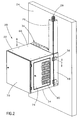
[00015] FIG. 1 is a top front left perspective view of a wall mount cabinet system according to the present invention;
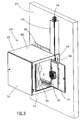
[00016] FIG. 2 is a top front right perspective view of the wall mount cabinet system of FIG. 1;
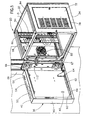
[00017] FIG. 3 is a top front right perspective view of the wall mount cabinet system of FIG. 2, showing the right side access panel in an open position;
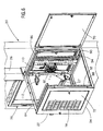
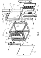
[00018] FIG. 4 is an enlarged view of the wall mount cabinet system of FIG. 1, showing the top panel removed and the front door and left and right side access panels in an open position;
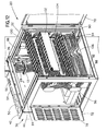
[00019] FIG. 5 is an enlarged view of the wall mount cabinet system of FIG. 1, showing the top panel removed and the cabinet in an open position;
[00020] FIG. 6 is an enlarged view of the wall mount cabinet system of FIG. 2, with the top panel removed and the front door and cabinet in an open position;
[00021] FIG. 7 is an exploded view of the wall mount cabinet system of FIG. 2;
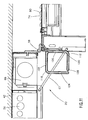
[00022] FIG. 8 is a cross-sectional view of the wall mount cabinet system taken along lines 8-8 of FIG. 2;
[00023] FIG. 9 is an enlarged view of the cable entrance area of FIG. 8;
[00024] FIG. 10 is an enlarged view of the wall mount cabinet system of FIG. 5; [00025] FIG. 11 is a top view of the wall mount cabinet system of FIG. 10;
[00026] FTG. 12 is a top front left perspective view of the wall mount cabinet system of FIG. 4, showing cables and optional equipment installed therein;
[00027] FIG. 13 is a top front left perspective view of the wall mount cabinet system of FIG. 5, showing cables and optional equipment installed therein;
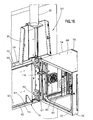
[00028] FIG. 14 is a top front left perspective view of the wall mount cabinet system of FIG. 1, showing the front door having a transparent window and conduit installed therein; 
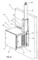
[00029] FIG. 15 is a top front right perspective view of the wall mount cabinet system of FIG. 2, showing a transition duct instead of a hinged duct; and
[00030] FIG. 16 is a top front left perspective view of the wall mount cabinet system of FIG. 12, showing the cabinet and transition duct in an open position.
[00031] The illustrated embodiments of the invention are directed to a wall mount cabinet system 20. FIGS. 1-14 show wall mount cabinet system 20 comprising a cabinet 22 mounted to a wall 24 and a hinged duct 26 for receiving cables 28 passing vertically therethrough. As best seen in FIG. 13, hinged duct 26 allows access to cables 28 when cabinet 22 is in an open position. Alternatively, as shown in FIGS. 15 and 16, transition duct 30 may be utilized instead of hinged duct 26. Transition duct 30 also allows access to cables 28 passing through conduit 32 when cabinet 22 is in an open position.
[00032] As shown in FIGS. 1-3, cabinet 22 includes a front section 34 and a rear section 36. Front section 34 is hingedly connected to rear section 36 at a pivot point 38, shown in FIGS. 9 and 11, and rear section 36 is mounted to wall 24. As best seen in FIG. 5, rear section 36 includes four keyholes 40 for mounting rear section 36 to wall 24. Although rear section 36 is illustrated in FIGS. 1-16 mounted to wall 24, it is likewise contemplated that rear section 36 may be mounted to other structures, such as a 7/8 inch or 1 5/8 inch Unistrut® channel on a wall.
[00033] Rear section 36 has a top side 42, a bottom side 44, a left side 46 and a right side 48. As best seen in FIG. 5, top side 42 includes three knockouts 50 for receiving 2 inch diameter conduit 52 (see FIG. 14), a knockout 54 for receiving a raceway section, and three knockouts 56 for receiving 2 inch or : inch diameter conduit 58 (see FIG. 14). Likewise, bottom side 44 includes three knockouts 60 for receiving 2 inch diameter conduit, a knockout 62 for receiving a raceway section, and three knockouts 64 for receiving 2 inch or : inch diameter conduit.
[00034] As shown in FIGS. 5 and 10, rear section 36 has a cutout area 66 at one end of top side 42 adjacent right side 48. When cabinet 22 is in a closed position, cutout area 66 is vertically aligned with hinged duct 26, as best seen in FIG. 12, to allow cables 28 to pass vertically therethrough into cabinet 22. Cutout area 66 allows cables 28 to be installed without having to thread cables 28 through an opening or a knockout. As best seen in FIGS. 9 and 11, pivot point 38 is located adjacent cutout area 66. The proximity of pivot point 38 to cutout area 66 minimizes movement of cables 28 when cabinet 22 is moved from the closed position to the open position, as cables 28 rotate about pivot point 38. As shown in FIG. 13, when cabinet 22 is moved from the closed position to the open position, cables 28 are displaced within hinged duct 26 as cables 28 rotate about pivot point 38.
[00035] As best seen in FIG. 11, rod 67 is inserted into a slot in each of front section 34 and rear section 36. Rod 67 maintains front section 34 in an open position about 90 degrees from rear section 36. It is likewise contemplated that rod 67 may be sized and configured to maintain front section 34 in an open position at any angular orientation between 0 and about 100 degrees with respect to rear section 36. Without rod 67 in place, front section 34 has a tendency to move toward rear section 36 and, thus, make it difficult for a user to have uninterrupted access to cables 28. When not in use, rod 67 may be secured to the inside surface of rear section 36 utilizing a clip or other securement devices known in the art.
[00036] As shown in FIGS. 1 and 2, front section 34 of cabinet 22 includes a top panel 68, a front door 70, a left side access panel 72 and a right side access panel 74. Left side access panel 72 and right side access panel 74 are hingedly connected to cabinet 22. Similarly, front door 70 is hingedly connected to cabinet 22. Although front door 70 is shown in FIGS. 1-7 as solid, it is likewise contemplated that front door 70 may have a transparent window 76, as best seen in FIG. 14. Each of front door 70, left side access panel 72 and right side access panel 74 is provided with locks for security and are keyed alike. Similarly, front section 34 is provided with a lock for security and is keyed alike. [00037] As shown in FIG. 4, left side access panel 72 includes vent louvers 78 to optimize air flow and ventilation within cabinet 22. Similarly, as shown in FIG. 2, right side access panel 74 includes vent louvers 80 to optimize air flow and ventilation within cabinet 22. Moreover, as best seen in FIG. 3, right side access panel 74 may include a fan assembly 82 secured therein. Alternatively, left side access panel 72 may include fan assembly 82 secured therein.
[00038] As best seen in FIG. 4, front section 34 of cabinet 22 has two top rails 84, 86, each rail extending from near front door 70 to near rear section 36 of cabinet 22. Similarly, front section 34 includes two bottom rails 88, 90 extending from near front door 70 to near rear section 36 of cabinet 22. Preferably, bottom rails 88, 90 are vertically aligned with top rails 84, 86, respectively. Moreover, two vertical rails 92, 94 are mounted to top rails 84, 86 and bottom rails 88, 90, respectively, near front door 70. Vertical rails 92, 94 are adjustable from front to rear in one inch increments. Preferably, vertical rails 92, 94 include marking indicia thereon.
[00039] As best seen in FIGS. 4 and 8, a slack cable manager 96 is secured to top rail 84 and bottom rail 88, adjacent left side access panel 72. Slack cable manager 96 provides slack storage for multiple length patch cords and is adjustable from front to rear in one inch increments. Similarly, as best seen in FIGS. 3 and 8, a slack cable manager 98 is secured to top rail 86 and bottom rail 90, adjacent right side access panel 74. Slack cable manager 98 provides slack storage for multiple length patch cords and is adjustable from front to rear in one inch increments.
[00040] As best seen in FIG. 12, front section 34 of cabinet 22 includes three horizontal cable managers, such as cable manager 100 without a cover and cable manager 102 with a hinged cover. Further, front section 34 of cabinet 22 includes two patch panels 104. Each of horizontal cable managers 100, 102 and patch panels 104 is secured to vertical rails 92, 94. Moreover, front section 34 of cabinet 22 includes active equipment 106, such as a Cisco® catalyst switch or a Nortel® baystack, secured to vertical rails 92, 94. Vertical rails 92, 94 are adjustable from front to rear, even after installation of slack cable managers 96, 98, horizontal cable managers 100, 102, patch panels 104 or active equipment 106. Preferably, cabinet 22 is 24 inches in depth to accommodate typical active equipment.
[00041] As best seen in FIG. 8, S- hooks 108, 110 may be secured to slack cable managers 96, 98, respectively. S- hooks 108, 110 manage cables within front section 34 of cabinet 22. S-hook 108 is positioned adjacent left side access panel 72, and S-hook 110 is positioned adjacent right side access panel 74. Alternatively, a D-ring (not shown), such as the one disclosed in U.S. Patent No. 6,427,952, which is hereby incorporated by reference, may be utilized instead of S- hooks 108, 110.
[00042] As best seen in FIG. 5, front section 34 of cabinet 22 includes a flexible D-ring 112 secured to a back edge of front section 34. As shown in FIGS. 4 and 12, when cabinet 22 is in the closed position, D-ring 112 is vertically aligned with cutout area 66 in rear section 34 of cabinet 22. D-ring 112 may be rotatably flexed to an open position which allows access to the maximum extent of the opening, thus permitting easier access for the larger cables or bundles of cables. As shown in FIG. 10, D-ring 112 includes mounting holes 114 on baseplate 116 which secures D-ring 112 in a desired position on front section 34 of cabinet 22. Preferably, D-ring 112 is formed of a strong but flexible, resilient plastic material, to have significant resistance to the flexing.
[00043] As best seen in FIG. 11, D-ring 112 has a baseplate 116 including a first arm 118 and a second arm 120. Preferably, first arm 118 and second arm 120 are substantially L-shaped. First arm 118 has a proximate portion 122 which extends in a generally linear fashion away from baseplate 116, and a distal portion 124 oriented substantially 90 degrees from proximate portion 122. First arm 118 may be twisted or rotated in either direction (up or down) at least 90 degrees. Similarly, second arm 120 has a proximate portion 126 which extends in a generally perpendicular fashion away from baseplate 116, and a distal portion 128 oriented substantially 90 degrees from proximate portion 126. Second arm 120 may be twisted or rotated in either direction (up or down) at least 90 degrees. Thus, D-ring 112 provides access to cables 28 secured therein from two directions. The twisting movement of first arm 118 and second arm 120 may be controlled by a desired cross-section and material selection. Consequently, a large number of cables, or large cables, may be expeditiously placed in or removed from D-ring 112 as a contiguous unit rather than on a piece-by-piece basis as is often required with prior art structures.
[00044] In operation, cabinet 22 is mounted to wall 24 adjacent hinged duct 26, as shown in FIGS. 1-3. As best seen in FIG. 13, front section 34 of cabinet 22 and hinged duct 26 are opened to allow access to cables 28 passing vertically through hinged duct 26 and into front section 34 of cabinet 22. Preferably, cables 28 are routed through D-ring 112, over S- hooks 108, 110 and into patch panels 104, horizontal cable managers 100, 102, active equipment 106 or slack cable managers 96, 98. When cabinet 22 is in a closed position, access to cables 28 is provided through left side access panel 72 and right side access panel 74, as shown in FIG. 12.
[00045] The disclosed invention provides a wall mount cabinet system having a cutout area in the rear section of the cabinet that offers the ability to install cables within the cabinet without having to thread the cables through an opening or knockout. It should be noted that the above-described illustrated embodiments and preferred embodiments of the invention are not an exhaustive listing of the forms such a wall mount cabinet system in accordance with the invention might take; rather, they serve as exemplary and illustrative of embodiments of the invention as presently understood. By way of example, and without limitation, the wall mount cabinet system may have more than one cutout area to allow the cabinet to open in either direction. Many other forms of the invention are believed to exist.

Claims (12)

  1. A wall mount cabinet (22) comprising:
    a rear section (36) having a first end and a second end, the rear section (36) including a cutout area (66) adjacent the first end, wherein the cutout area (66) allows access for cables (28) to enter the cabinet (22); and
    a front section (34) hingedly connected to the rear section (36) at a pivot point (38) adjacent the cutout area (66) and the first end of the rear section (36),
       wherein the cutout area (36) allows the cables (28) to rotate about the pivot point (38) when the cabinet (22) is moved from a closed position to an open position.
  2. A wall mount cabinet (22) comprising:
    a rear section (36) having a cutout area (66); and
    a front section (34) hingedly connected to the rear section (36), the front section (34) having a cable management ring (112) secured thereon,
       wherein when the cabinet (22) is in a closed position, the cable management ring (112) is vertically aligned with the cutout area (66).
  3. The wall mount cabinet (22) of claim 1 or claim 2, further comprising a hinged duct (126) or transition duct (30) positioned adjacent the cutout area (66).
  4. The wall mount cabinet (22) of claim 1 or claim 2, further comprising two side access panels (72, 74) hingedly connected to the front section (34).
  5. The wall mount cabinet (22) of claim 1 or claim 2, further comprising a front door (70) hingedly connected to the front section (34), wherein the front door (70) includes a transparent window (76).
  6. The wall mount cabinet (22) of claim 1 or claim 2, further comprising a rod (67) which maintains the front section (34) in an open position about 90 degrees from the rear section (36).
  7. The wall mount cabinet (22) of claim 1 or claim 2, wherein the front section (34) includes a slack cable manager (96) secured to a rail (84) mounted therein, or a patch panel (104) secured to a rail (84) mounted therein, or a horizontal cable manager (100) secured to a rail (84) mounted therein, or active equipment (106) secured to a rail mounted therein.
  8. The wall mount cabinet (22) of claim 2, wherein the rear section (36) has a first end and a second end, the cutout area (66) being adjacent the first end.
  9. The wall mount cabinet (22) of claim 2, wherein the cable management ring (112) has a first substantially L-shaped arm (118) having a distal portion (124) oriented substantially 90 degrees from a substantially linear portion (122), wherein the first arm (118) is formed of a material and construction selected to provide rotation from a first 90 degree angle to a second 90 degree angle of the distal portion (124) with respect to the proximate portion (122).
  10. The wall mount cabinet (22) of claim 1 or claim 5, wherein the front section (34) includes a rail (92) mounted therein, the rail (92) is adjustable from adjacent the front door (70) to adjacent the rear section (36).
  11. The wall mount cabinet (22) of claim 8, wherein the front section (34) is hingedly connected to the rear section (36) at a pivot point (38) adjacent the cutout area (66) and the first end of the rear section (36).
  12. The wall mount cabinet (22) of claim 9, further comprising a second substantially L-shaped arm (120) having a distal portion (128) oriented substantially 90 degrees from a substantially linear portion (126), wherein the second arm (120) is formed of a material and construction selected to provide rotation from a first 90 degree angle to a second 90 degree angle of the distal portion (128) with respect to the proximate portion (126).
EP05250906A 2004-02-17 2005-02-17 Wall mount cabinet system Withdrawn EP1565009A3 (en)

Applications Claiming Priority (2)

Application Number Priority Date Filing Date Title
US780320 2004-02-17
US10/780,320 US8091969B2 (en) 2004-02-17 2004-02-17 Wall mount cabinet system

Publications (2)

Publication Number Publication Date
EP1565009A2 true EP1565009A2 (en) 2005-08-17
EP1565009A3 EP1565009A3 (en) 2009-05-27

Family

ID=34701444

Family Applications (1)

Application Number Title Priority Date Filing Date
EP05250906A Withdrawn EP1565009A3 (en) 2004-02-17 2005-02-17 Wall mount cabinet system

Country Status (2)

Country Link
US (1) US8091969B2 (en)
EP (1) EP1565009A3 (en)

Cited By (3)

* Cited by examiner, † Cited by third party
Publication number Priority date Publication date Assignee Title
WO2008137389A1 (en) * 2007-05-07 2008-11-13 Adc Telecommunications, Inc. Modular optical wall box enclosure
EP3398879A1 (en) * 2017-05-04 2018-11-07 ESE World B.V. Cabinet for storing goods
CN116828339A (en) * 2023-08-28 2023-09-29 合肥岭雁科技有限公司 Home gateway convenient to install

Families Citing this family (12)

* Cited by examiner, † Cited by third party
Publication number Priority date Publication date Assignee Title
US7276659B2 (en) * 2005-05-31 2007-10-02 Hoffman Enclosures, Inc. Enclosure having a closure member
US7462779B2 (en) * 2005-09-08 2008-12-09 Panduit Corp. Wall mounted enclosure with rotating patch panel frame
US8650805B1 (en) * 2010-05-17 2014-02-18 Equinix, Inc. Systems and methods for DMARC in a cage mesh design
CN102821561A (en) * 2011-06-08 2012-12-12 鸿富锦精密工业(深圳)有限公司 Container data center
US9061316B2 (en) * 2011-10-28 2015-06-23 Nordson Corporation Mountable device for dispensing heated adhesive
CN202820186U (en) * 2012-06-05 2013-03-27 曜嘉科技股份有限公司 Digital furniture
USD736198S1 (en) * 2012-06-15 2015-08-11 Scott P. Merbeth Wall mounted computer case
US9693478B2 (en) * 2013-07-02 2017-06-27 Atlas Sound Lp Wall-mounted articulating half rack cabinet system
US9226579B2 (en) * 2012-11-02 2016-01-05 Paragon Furniture LP Modular desk systems and methods
US11122701B2 (en) * 2019-02-15 2021-09-14 Hubbell Incorporated Wall mounted utility cabinet
CN110677350A (en) * 2019-10-18 2020-01-10 陆易 Extensible wireless router
WO2021154161A1 (en) * 2020-01-31 2021-08-05 Sajchwong Apichart 19-inch symmetrical wall-mounted 2-piece cabinet

Citations (3)

* Cited by examiner, † Cited by third party
Publication number Priority date Publication date Assignee Title
US5001602A (en) * 1988-11-28 1991-03-19 Reliance Comm/Tec Corporation Network interface cabinet for large pair count telephone terminations
WO1999027404A1 (en) * 1997-11-20 1999-06-03 Siemens Aktiengesellschaft Device for guiding lines in communication systems
US20020197045A1 (en) * 2001-06-26 2002-12-26 Schmidt John David Cable management brackets and cabinet

Family Cites Families (29)

* Cited by examiner, † Cited by third party
Publication number Priority date Publication date Assignee Title
US3006498A (en) * 1959-01-15 1961-10-31 Albert B Thiede Air-conditioner cover
US3623784A (en) * 1969-11-05 1971-11-30 Massey Ferguson Ind Ltd Cabinet joint structure
US3659319A (en) * 1970-11-30 1972-05-02 Lloyd A Erickson Adhesive wire routing clip
US3794395A (en) * 1972-05-01 1974-02-26 Hill Rom Co Inc Cabinet
US4824196A (en) * 1987-05-26 1989-04-25 Minnesota Mining And Manufacturing Company Optical fiber distribution panel
US5065968A (en) * 1990-10-25 1991-11-19 Hubbell Incorporated Electrical box mounting apparatus
US5408045A (en) * 1992-01-10 1995-04-18 Hubbell Incorporated Electrical box assembly with mounting bracket
US5239129A (en) * 1992-04-06 1993-08-24 Hubbell Incorporated Housing for switched electrical receptacle or the like
SE505801C2 (en) * 1992-09-25 1997-10-13 Atlas Copco Tools Ab Cabinets for holding electronic equipment connectable to machines or power tools
US5367598A (en) * 1993-10-21 1994-11-22 Nec America, Inc. Interface chassis for fiber optic transport system
DE19507738C2 (en) * 1995-03-07 1997-05-28 Loh Kg Rittal Werk Control cabinet with a frame
US5765698A (en) * 1996-09-04 1998-06-16 Hubbell Incorporated Panel assembly with angularly oriented hinges
US6019321A (en) * 1996-12-30 2000-02-01 The Siemon Company Modular furniture interconnection panel
US5997117A (en) * 1997-06-06 1999-12-07 Chatsworth Products, Inc. Rack frame cabinet
US5933563A (en) * 1997-10-14 1999-08-03 The Whitaker Corporation Cable enclosure with pass through
US6067233A (en) * 1998-02-27 2000-05-23 3Com Corporation Mounting brace and cable management apparatus and method
US6170928B1 (en) * 1998-06-29 2001-01-09 Lucent Technologies Inc. Multi-latch door for electrical cabinets
US6061966A (en) * 1998-06-30 2000-05-16 Emc Corporation Electrical cabinet having a door stop
US6203130B1 (en) * 1999-06-21 2001-03-20 Hubbell Incorporated Enhanced telecommunications cabinet assembly having movable wiring interconnect management tray removably supporting modular interconnect panels
EP1252694B1 (en) * 1999-12-15 2009-04-15 Panduit Corp. Cable management ring
US6460951B1 (en) * 1999-12-20 2002-10-08 Hubbell Incorporated Telecommunications enclosure box employing mounting brackets for supporting components providing communicative connection of remote multimedia equipment
US6185098B1 (en) * 2000-01-31 2001-02-06 Chatsworth Products, Inc. Co-location server cabinet
US6394398B1 (en) * 2000-06-22 2002-05-28 Chatsworth Products, Inc. Modular inter-cabinet horizontal cable support apparatus
US6755493B1 (en) * 2000-09-19 2004-06-29 Chatsworth Products, Inc. Wall mounted cabinet having improved hinge design
US6504100B2 (en) * 2000-12-20 2003-01-07 Chatsworth Products, Inc. Flexible intra-cabinet cable ring wire management system
US6501020B2 (en) * 2001-01-15 2002-12-31 Chatsworth Products, Inc. Electrical equipment and cable support assembly
US6613981B1 (en) * 2001-10-17 2003-09-02 Chatsworth Products, Inc. Pivotable cable ring wire management system
US7097047B2 (en) * 2003-09-30 2006-08-29 Dell Products L.P. Cable management flip tray assembly
US6946600B1 (en) * 2004-03-01 2005-09-20 Commscope Solutions Properties, Llc. Cabinet with cross-connect that provides access to rear side of electronic equipment

Patent Citations (3)

* Cited by examiner, † Cited by third party
Publication number Priority date Publication date Assignee Title
US5001602A (en) * 1988-11-28 1991-03-19 Reliance Comm/Tec Corporation Network interface cabinet for large pair count telephone terminations
WO1999027404A1 (en) * 1997-11-20 1999-06-03 Siemens Aktiengesellschaft Device for guiding lines in communication systems
US20020197045A1 (en) * 2001-06-26 2002-12-26 Schmidt John David Cable management brackets and cabinet

Cited By (6)

* Cited by examiner, † Cited by third party
Publication number Priority date Publication date Assignee Title
WO2008137389A1 (en) * 2007-05-07 2008-11-13 Adc Telecommunications, Inc. Modular optical wall box enclosure
US7493003B2 (en) 2007-05-07 2009-02-17 Adc Telecommunications, Inc. Modular optical wall box enclosure
US7817895B2 (en) 2007-05-07 2010-10-19 Adc Telecommunications, Inc. Modular optical wall box enclosure
EP3398879A1 (en) * 2017-05-04 2018-11-07 ESE World B.V. Cabinet for storing goods
CN116828339A (en) * 2023-08-28 2023-09-29 合肥岭雁科技有限公司 Home gateway convenient to install
CN116828339B (en) * 2023-08-28 2023-10-31 合肥岭雁科技有限公司 Home gateway convenient to install

Also Published As

Publication number Publication date
US8091969B2 (en) 2012-01-10
EP1565009A3 (en) 2009-05-27
US20050179348A1 (en) 2005-08-18

Similar Documents

Publication Publication Date Title
EP1565009A2 (en) Wall mount cabinet system
US7956284B2 (en) In-ceiling zone cabling enclosure
US8038015B2 (en) Equipment rack panel system and method
US5911661A (en) Zone cabling termination cabinet
US7462779B2 (en) Wall mounted enclosure with rotating patch panel frame
US4371757A (en) Enclosure for outdoor cross-connect system for telecommunications
US8435086B2 (en) Vertical cable manager
CN1223206C (en) Cable manager for network rack
US6791841B1 (en) Methods and apparatus for managing a set of cables
US20080180004A1 (en) Modular telecommunications frame and enclosure assembly
US6924989B2 (en) Wire and system component management system
US20080289873A1 (en) Network enclosure with removable and interchangeable sides
CN1726748A (en) Outdoor electronic equipment cabinet
WO1998035175A2 (en) Vertical cable manager
CA2533486A1 (en) Cable management rack
US20050017610A1 (en) Water-shedding indoor wall mounted cabinet
KR102222286B1 (en) Enclosure for communication cable
US7728224B2 (en) Field convertible telecommunications distribution pedestal
US20090050363A1 (en) Cable mounting structure and snap fit door hinge for telecommunications distribution pedestal
US10526831B2 (en) Door and suspension mechanism assembly and an assembly of an elongated housing and a door and suspension mechanism assembly
JP2004039820A (en) Equipment housing box
US20170322385A1 (en) Telecommunications zone enclosure
CN216119809U (en) Novel outdoor cabinet of transformer
EP0867994A2 (en) Duct system for electrical installations
CN114390829A (en) Multimedia box

Legal Events

Date Code Title Description
PUAI Public reference made under article 153(3) epc to a published international application that has entered the european phase

Free format text: ORIGINAL CODE: 0009012

AK Designated contracting states

Kind code of ref document: A2

Designated state(s): AT BE BG CH CY CZ DE DK EE ES FI FR GB GR HU IE IS IT LI LT LU MC NL PL PT RO SE SI SK TR

AX Request for extension of the european patent

Extension state: AL BA HR LV MK YU

PUAL Search report despatched

Free format text: ORIGINAL CODE: 0009013

AK Designated contracting states

Kind code of ref document: A3

Designated state(s): AT BE BG CH CY CZ DE DK EE ES FI FR GB GR HU IE IS IT LI LT LU MC NL PL PT RO SE SI SK TR

AX Request for extension of the european patent

Extension state: AL BA HR LV MK YU

STAA Information on the status of an ep patent application or granted ep patent

Free format text: STATUS: THE APPLICATION IS DEEMED TO BE WITHDRAWN

AKX Designation fees paid
18D Application deemed to be withdrawn

Effective date: 20090901

REG Reference to a national code

Ref country code: DE

Ref legal event code: 8566