EP1564996A1 - Entrance video surveillance system - Google Patents
Entrance video surveillance system Download PDFInfo
- Publication number
- EP1564996A1 EP1564996A1 EP03730220A EP03730220A EP1564996A1 EP 1564996 A1 EP1564996 A1 EP 1564996A1 EP 03730220 A EP03730220 A EP 03730220A EP 03730220 A EP03730220 A EP 03730220A EP 1564996 A1 EP1564996 A1 EP 1564996A1
- Authority
- EP
- European Patent Office
- Prior art keywords
- video
- entry system
- system terminal
- video entry
- television channels
- Prior art date
- Legal status (The legal status is an assumption and is not a legal conclusion. Google has not performed a legal analysis and makes no representation as to the accuracy of the status listed.)
- Withdrawn
Links
- 230000005540 biological transmission Effects 0.000 description 3
- 238000010586 diagram Methods 0.000 description 3
- 241000894339 Matucare virus Species 0.000 description 2
- 230000006870 function Effects 0.000 description 2
- 238000001914 filtration Methods 0.000 description 1
- 239000002699 waste material Substances 0.000 description 1
Images


Classifications
-
- H—ELECTRICITY
- H04—ELECTRIC COMMUNICATION TECHNIQUE
- H04M—TELEPHONIC COMMUNICATION
- H04M11/00—Telephonic communication systems specially adapted for combination with other electrical systems
- H04M11/02—Telephonic communication systems specially adapted for combination with other electrical systems with bell or annunciator systems
- H04M11/025—Door telephones
-
- H—ELECTRICITY
- H04—ELECTRIC COMMUNICATION TECHNIQUE
- H04N—PICTORIAL COMMUNICATION, e.g. TELEVISION
- H04N7/00—Television systems
- H04N7/18—Closed-circuit television [CCTV] systems, i.e. systems in which the video signal is not broadcast
- H04N7/183—Closed-circuit television [CCTV] systems, i.e. systems in which the video signal is not broadcast for receiving images from a single remote source
- H04N7/186—Video door telephones
Definitions
- This invention relates to a video entry system terminal according to claim 1.
- Different video entry systems are known that generally include one or several outside modules and various user terminals.
- the outside modules which are situated outside the corresponding access door, basically consist of a video camera, a microphone-speaker set and a buzzer for calling.
- the user terminals are situated in the users' homes and consist of a video monitor, a telephone handset and devices for opening the access door.
- the communication allows a two-directional audio exchange and allows the user to view on the video monitor the images captured by the video camera situated in the outside module from which the call is made. It also allows the access door to be opened from the user's terminal.
- a video entry system terminal is disclosed in the Spanish patent ES 2120380.
- the objective of this invention is to develop a video entry system that can be used as a terminal for other services.
- the invention has a plurality of advantages.
- a video entry system terminal has means for receiving Television channels.
- a terminal like this allows it to be used as a television receiver, which also makes it possible to use it for entertainment, information, education, etc. and all the purposes in general that television has.
- a video entry system terminal is characterised in that the means of receiving Television channels consist of a tuner/demodulator. This allows the tuning and reception of any television channel that is broadcast in the area by selecting the channel to be received at all times.
- video entry system terminal Another example of a video entry system terminal according to the invention is characterised in that the video monitor consists of a touch screen, making it possible to use said monitor for other purposes such as the simple entry any kind of data into the video door entry system terminal.
- FIG. 1 Another example of a video entry system terminal according to the invention is characterised in that it has a user interface for entering data, allowing the different television, video door entry system, etc. services to be programmed.
- FIG. 1 Another example of a video entry system terminal according to the invention is characterised in that the user interface consists of a keypad.
- FIG. 1 Another example of a video entry system terminal according to the invention is characterised in that the user consists of a touch screen for the video monitor. This makes it easier to enter data by means of an on-screen menu and allows one to navigate using said menus. It also reduces space by making the keypad unnecessary.
- the video entry system terminal may also include other services such as:
- the video entry system terminal includes an analogue and digital TV tuner/demodulator, a device for entering text, a TFT touch screen, a DATA-VOICE modem and a microcontroller with flash memory.
- the signal from the video entry system network contains television channels and/or specific video entry system network information so that the terminal can be connected to said network.
- This different information is separated by the filtering system. All the specific network information is demodulated, or modulated if it is generated by the terminal itself, in the DATA-VOICE modem.
- This information is what allows the video entry system terminal access to the intercom, switchboard, low-speed data and Internet access services.
- the device for entering text, the keypad and TFT touch screen carry out the interface functions that allow the aforementioned services to be enjoyed.
- the microcontroller provides the mechanism that allows connections to be made between the video entry system terminal and the network base, as well as managing the terminal's different components.
- there is a power supply allowing both continuous and alternating current, that provides the power for all the devices in the circuit to work.
- the video entry system terminal uses a tuner which consists of a tuning section with tracking filters and another section made up of mixers and oscillators that will be used according to the input frequency that is to be tuned.
- the filter section is made with three input stages depending on which band is to be tuned. Each of them is made up of two filter stages, the tuning of which is controlled by the same current that controls the oscillator that attacks that mixer of the same band.
- the outputs of these sections enter a three-band mixer/oscillator.
- Each oscillator is controlled by a current the same as that which controls the filters. Said current is generated in the PLL which is controlled by the microcontroller by bus 12C.
- the output of the tuner is in 38.9Mhz and is entered into both the analogue and digital demodulators.
- the output from each of these stages, audio and video, is entered into a switch that allows the type of transmission to be seen on the screen to be selected. All the devices involved in the demodulation are controlled by the processor.
- Video entry system terminal According to the invention, a preferred nonlimiting embodiment of a Video entry system terminal according to the invention is described as follows.
- the video entry system terminal consists of means of connection (connectors) 2, an input filter system 3 consisting of a high-pass filter 31 and a low-pass filter 32, a TV tuner/demodulator 4, a device for entering text 5, a TFT touch screen 6, a Microprocessor 7, a DATA-VOICE Modem 8, a Keypad 9, a Loudspeaker 10, a microphone 11 and a power supply 12.
- the Video entry system terminal 1 is connected to the video entry system and/or Television network by the connectors 2.
- the input filter system 3 separates the Television signals from the specific signals of the video entry system network. The latter are entered (in the event of reception) or extracted (in the case of transmission) in the DATA-VOICE Modem 8.
- the Television signals within the 470 to 869 Mhz band are filtered in 3 and entered into the TV tuner/demodulator 4. Then the television signal passes through a device for entering text 5 and is then presented on a TFT screen 6.
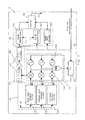
- FIG. 2 shows the block diagram of the TV tuner/demodulator 4.
- said device 4 consists of a tuner section consisting of a first filter stage 13 using tracking filters and a mixer stage 14 made up of mixers 141 and oscillators 142.
- the filter stage 13 consists of three input filter sections 131 that depend on which band is to be tuned. Each of them is made up of two tracking filters, the tuning of which is controlled by the same current that controls the corresponding oscillator 142 that attacks the mixer 141 of the same band.
- Each oscillator 142 is controlled by a current the same as that which controls the tracking filters in the corresponding filter section 131.
- Said current is generated in the PLL 15, which is controlled by the microprocessor 7 by a Bus 12C 16.
- the output from the mixers 141 is entered into an intermediate filter stage 21 at a frequency of 38.9Mhz.
- the intermediate filter stage 21 consists of two filters 17 and an amplifier 19.
- the signal is entered into the demodulators 18, which are both analogue 181 and digital 182, and in the latter case the signal is then entered into a MPEG decoder 183.
- the outputs (audio and video) from each of the demodulators 18 are entered into a switch 20 which allows the type of transmission to be seen on the screen 6 to be selected.
- the signal selected in the switch 20 is entered into a device for entering texts 5 and is then entered onto the screen 6 (figure 1).
- FIG 3 shows an alternative embodiment of the invention, in which it can be seen that the video entry system terminal 1 has a built-in aerial 21 that allows Television channels to be received directly. Said aerial 21 is connected directly to the input of the TV tuner/demodulator 4.
- FIG. 4 shows an alternative embodiment of the invention, in which it can be seen that the video entry system terminal 1 has coaxial connectors to connect an external television aerial 23 or to a MATV/SMATV network and connectors 2 to connect to the video entry system network.
- both connections are independent, as the connections are made directly from the video entry system network to the DATA-VOICE modem 8 and from the external television aerial 23 or from the MATV/SMATV network to the TV tuner/demodulator 4.
Landscapes
- Engineering & Computer Science (AREA)
- Signal Processing (AREA)
- Multimedia (AREA)
- Closed-Circuit Television Systems (AREA)
- Two-Way Televisions, Distribution Of Moving Picture Or The Like (AREA)
- Interconnected Communication Systems, Intercoms, And Interphones (AREA)
Abstract
Video surveillance terminal comprising elements for exchanging audio with street
units, a video monitor for viewing images captured by video cameras installed in the
streets units and a device for opening the door of entrance which is provided with
means of receiving television channels. The means of receiving television channels
comprise a tuner and a modulator and the video monitor comprises a touch screen.
Furthermore an antenna for the direct reception of television channels and a user
interface for the selection of channels and for adjusting parameters is provided and
which is constituted of a keyboaord and/or a touch screen.
Description
- This invention relates to a video entry system terminal according to
claim 1. - Different video entry systems are known that generally include one or several outside modules and various user terminals.
- The outside modules, which are situated outside the corresponding access door, basically consist of a video camera, a microphone-speaker set and a buzzer for calling.
- The user terminals are situated in the users' homes and consist of a video monitor, a telephone handset and devices for opening the access door.
- Communication is established between the outside module and the user's terminal when someone uses the buzzer to call.
- The communication allows a two-directional audio exchange and allows the user to view on the video monitor the images captured by the video camera situated in the outside module from which the call is made. It also allows the access door to be opened from the user's terminal.
- A video entry system terminal is disclosed in the Spanish patent ES 2120380.
- These user terminals have the drawback that they may only be used for the video entry service with the resulting waste that this involves. Likewise, this involves having many terminals for the various services with the drawbacks that this involves.
- The objective of this invention is to develop a video entry system that can be used as a terminal for other services.
- This objective is attained using a video entry system terminal established in the claims.
- The invention has a plurality of advantages.
- In one example according to the invention, a video entry system terminal has means for receiving Television channels. A terminal like this allows it to be used as a television receiver, which also makes it possible to use it for entertainment, information, education, etc. and all the purposes in general that television has.
- Another example of a video entry system terminal according to the invention is characterised in that the means of receiving Television channels consist of a tuner/demodulator. This allows the tuning and reception of any television channel that is broadcast in the area by selecting the channel to be received at all times.
- Another example of a video entry system terminal according to the invention is characterised in that the video monitor consists of a touch screen, making it possible to use said monitor for other purposes such as the simple entry any kind of data into the video door entry system terminal.
- Another example of a video entry system terminal according to the invention is characterised in that it has a user interface for entering data, allowing the different television, video door entry system, etc. services to be programmed.
- Another example of a video entry system terminal according to the invention is characterised in that the user interface consists of a keypad.
- Another example of a video entry system terminal according to the invention is characterised in that the user consists of a touch screen for the video monitor. This makes it easier to enter data by means of an on-screen menu and allows one to navigate using said menus. It also reduces space by making the keypad unnecessary.
- As well as video entry system and television services, the video entry system terminal according to the invention may also include other services such as:
- An intercom between the components connected to the Video entry system network.
- Connection to the telephone switchboard.
- Internet access.
-
- To carry out all these functions the video entry system terminal according to the invention includes an analogue and digital TV tuner/demodulator, a device for entering text, a TFT touch screen, a DATA-VOICE modem and a microcontroller with flash memory.
- In a Video entry system terminal like that of the invention the signal from the video entry system network contains television channels and/or specific video entry system network information so that the terminal can be connected to said network. This different information is separated by the filtering system. All the specific network information is demodulated, or modulated if it is generated by the terminal itself, in the DATA-VOICE modem. This information is what allows the video entry system terminal access to the intercom, switchboard, low-speed data and Internet access services. The device for entering text, the keypad and TFT touch screen carry out the interface functions that allow the aforementioned services to be enjoyed. The microcontroller provides the mechanism that allows connections to be made between the video entry system terminal and the network base, as well as managing the terminal's different components. Lastly, there is a power supply, allowing both continuous and alternating current, that provides the power for all the devices in the circuit to work.
- For the reception of television signals the video entry system terminal according to the invention uses a tuner which consists of a tuning section with tracking filters and another section made up of mixers and oscillators that will be used according to the input frequency that is to be tuned. The filter section is made with three input stages depending on which band is to be tuned. Each of them is made up of two filter stages, the tuning of which is controlled by the same current that controls the oscillator that attacks that mixer of the same band. The outputs of these sections enter a three-band mixer/oscillator. Each oscillator is controlled by a current the same as that which controls the filters. Said current is generated in the PLL which is controlled by the microcontroller by bus 12C. The output of the tuner is in 38.9Mhz and is entered into both the analogue and digital demodulators. The output from each of these stages, audio and video, is entered into a switch that allows the type of transmission to be seen on the screen to be selected. All the devices involved in the demodulation are controlled by the processor.
- By way of an example, and based on the figures given below, a preferred nonlimiting embodiment of a Video entry system terminal according to the invention is described as follows.
- Figure 1
- is a block diagram of the video entry system terminal according to the invention.
- Figure 2
- is a block diagram of the television reception system of the video entry system terminal according to the invention.
- Figure 3
- shows an alternative embodiment of the video entry system terminal according to the invention.
- Figure 4
- shows an alternative embodiment of the video entry system terminal according to the invention.
- As can be seen in figure 1, the video entry system terminal consists of means of connection (connectors) 2, an
input filter system 3 consisting of a high-pass filter 31 and a low-pass filter 32, a TV tuner/demodulator 4, a device for enteringtext 5, aTFT touch screen 6, aMicroprocessor 7, a DATA-VOICE Modem 8, a Keypad 9, a Loudspeaker 10, amicrophone 11 and apower supply 12. - The Video
entry system terminal 1 is connected to the video entry system and/or Television network by theconnectors 2. Theinput filter system 3 separates the Television signals from the specific signals of the video entry system network. The latter are entered (in the event of reception) or extracted (in the case of transmission) in the DATA-VOICE Modem 8. - The Television signals within the 470 to 869 Mhz band are filtered in 3 and entered into the TV tuner/
demodulator 4. Then the television signal passes through a device for enteringtext 5 and is then presented on aTFT screen 6. - Figure 2 shows the block diagram of the TV tuner/
demodulator 4. - As can be seen, said
device 4 consists of a tuner section consisting of afirst filter stage 13 using tracking filters and amixer stage 14 made up ofmixers 141 andoscillators 142. - The
filter stage 13 consists of three input filter sections 131 that depend on which band is to be tuned. Each of them is made up of two tracking filters, the tuning of which is controlled by the same current that controls thecorresponding oscillator 142 that attacks themixer 141 of the same band. - The outputs from the sections in 131 are entered into the
mixers 141. Eachoscillator 142 is controlled by a current the same as that which controls the tracking filters in the corresponding filter section 131. - Said current is generated in the
PLL 15, which is controlled by themicroprocessor 7 by aBus 12C 16. - The output from the
mixers 141 is entered into anintermediate filter stage 21 at a frequency of 38.9Mhz. Theintermediate filter stage 21 consists of twofilters 17 and anamplifier 19. - Once the signal has been filtered, it is entered into the
demodulators 18, which are both analogue 181 and digital 182, and in the latter case the signal is then entered into aMPEG decoder 183. The outputs (audio and video) from each of thedemodulators 18 are entered into aswitch 20 which allows the type of transmission to be seen on thescreen 6 to be selected. The signal selected in theswitch 20 is entered into a device for enteringtexts 5 and is then entered onto the screen 6 (figure 1). - All the devices involved in the demodulation are controlled by the
microprocessor 7 by means of different buses, especiallyBus 12C 16. - Figure 3 shows an alternative embodiment of the invention, in which it can be seen that the video
entry system terminal 1 has a built-in aerial 21 that allows Television channels to be received directly. Said aerial 21 is connected directly to the input of the TV tuner/demodulator 4. - Figure 4 shows an alternative embodiment of the invention, in which it can be seen that the video
entry system terminal 1 has coaxial connectors to connect an external television aerial 23 or to a MATV/SMATV network andconnectors 2 to connect to the video entry system network. - In this case both connections are independent, as the connections are made directly from the video entry system network to the DATA-
VOICE modem 8 and from the external television aerial 23 or from the MATV/SMATV network to the TV tuner/demodulator 4. -
- 1.-
- Video entry system terminal
- 2.-
- Means of connection (connectors)
- 3.-
- Input filter system
- 31.-
- High-pass filter
- 32.-
- Low-pass filter
- 4.-
- TV tuner/demodulator
- 5.-
- Devise for entering Text (OSD)
- 6.-
- Screen
- 7.-
- Microprocessor
- 8.-
- DATA-VOICE MODEM
- 9.-
- Keypad
- 10.-
- Loudspeaker
- 11.-
- Microphone
- 12.-
- Power Supply
- 13.-
- Filter Stage
- 131.-
- Filter Section
- 14.-
- Mixer Stage
- 141.-
- Mixers
- 142.-
- Oscillators
- 15.-
- Phase Locked Loop (PLL)
- 16.-
- Bus 12C
- 17.-
- Filters
- 18.-
- Demodulators
- 19.-
- Amplifier
- 20.-
- Switch
- 21.-
- Aerial
- 22.-
- Coaxial Connectors
- 23.-
- External Television Aerial
Claims (7)
- Video entry system terminal consisting of means of audio exchange with outside modules, a video monitor to view the images captured by the video cameras situated in the outside modules and a device for opening the access door.
Characterised:In that it has means of receiving Television channels. - Video entry system terminal, according to claim 1, characterised in that the means of receiving Television channels consist of a tuner and modulator.
- Video entry system terminal, according to claims 1 and 2, characterised in that the video monitor consists of a touch screen.
- Video entry system terminal, according to claims 1 and 2, characterised in that it has an aerial for directly receiving Television channels.
- Video entry system terminal, according to the previous claims,
characterised in that it has a user interface for selecting channels and adjusting parameters. - Video entry system terminal, according to the previous claims,
characterised in that the user interface consists of a keypad. - Video entry system terminal, according to claims 1 and 2, characterised in that the user interface consists of a touch screen.
Applications Claiming Priority (3)
| Application Number | Priority Date | Filing Date | Title |
|---|---|---|---|
| ES200201372A ES2197021B1 (en) | 2002-06-11 | 2002-06-11 | VIDEOPORTERY TERMINAL. |
| ES200201372 | 2002-06-11 | ||
| PCT/ES2003/000281 WO2003105479A1 (en) | 2002-06-11 | 2003-06-10 | Entrance video surveillance system |
Publications (1)
| Publication Number | Publication Date |
|---|---|
| EP1564996A1 true EP1564996A1 (en) | 2005-08-17 |
Family
ID=29724730
Family Applications (1)
| Application Number | Title | Priority Date | Filing Date |
|---|---|---|---|
| EP03730220A Withdrawn EP1564996A1 (en) | 2002-06-11 | 2003-06-10 | Entrance video surveillance system |
Country Status (4)
| Country | Link |
|---|---|
| EP (1) | EP1564996A1 (en) |
| AU (1) | AU2003240854A1 (en) |
| ES (1) | ES2197021B1 (en) |
| WO (1) | WO2003105479A1 (en) |
Families Citing this family (3)
| Publication number | Priority date | Publication date | Assignee | Title |
|---|---|---|---|---|
| NL1025693C2 (en) * | 2004-03-11 | 2005-09-13 | Venta B V | Intercom panel, has touch screen for selecting occupier and displaying door bell icon for activating telephone, intercom or door bell |
| ES1060752Y (en) * | 2005-07-19 | 2006-02-16 | Alfonso Garcia Javier De | RINGER-ANSWER |
| ES2288089B1 (en) * | 2005-08-19 | 2008-10-16 | Ramon Jesus Martin Robaina | AUTOMATIC VISIT CONTROL. |
Family Cites Families (3)
| Publication number | Priority date | Publication date | Assignee | Title |
|---|---|---|---|---|
| ES2005874A6 (en) * | 1987-05-19 | 1989-04-01 | Palomares Marcen Fernando | Videoportero by television channel (Machine-translation by Google Translate, not legally binding) |
| KR950005150B1 (en) * | 1992-03-23 | 1995-05-18 | 조명언 | Portable TV combined video monitor |
| DE19616282A1 (en) * | 1996-04-24 | 1997-11-06 | Rft E Electronic Gmbh | Door intercom and video system |
-
2002
- 2002-06-11 ES ES200201372A patent/ES2197021B1/en not_active Expired - Fee Related
-
2003
- 2003-06-10 EP EP03730220A patent/EP1564996A1/en not_active Withdrawn
- 2003-06-10 WO PCT/ES2003/000281 patent/WO2003105479A1/en not_active Ceased
- 2003-06-10 AU AU2003240854A patent/AU2003240854A1/en not_active Abandoned
Non-Patent Citations (1)
| Title |
|---|
| See references of WO03105479A1 * |
Also Published As
| Publication number | Publication date |
|---|---|
| ES2197021A1 (en) | 2003-12-16 |
| AU2003240854A1 (en) | 2003-12-22 |
| WO2003105479A1 (en) | 2003-12-18 |
| ES2197021B1 (en) | 2005-05-16 |
Similar Documents
| Publication | Publication Date | Title |
|---|---|---|
| WO2003107537A2 (en) | Method and apparatus for implementing a scaled upgrading of an upgradeable set-top box | |
| KR20030013459A (en) | Wireless communication point of deployment module for use in digital cable compliant devices | |
| JP2002522978A (en) | Audio / video signal redistribution system | |
| JP2000511734A (en) | Program guide for DBS and cable TV | |
| US20040155961A1 (en) | Apparatus and method for controlling display of video camera signals received over a powerline network | |
| EP1156677B1 (en) | Tuner | |
| EP1564996A1 (en) | Entrance video surveillance system | |
| JPH10336614A (en) | Multi-unit housing multimedia system | |
| EP1065869A2 (en) | Internet telephone system using CATV and terminal device | |
| KR100369998B1 (en) | Restriction on TV paid channel viewing | |
| KR100518364B1 (en) | Multimedia integration system for a domestic | |
| KR100279354B1 (en) | Wired / wireless automatic control device for home multimedia system | |
| KR100727271B1 (en) | Multiple Output Broadcasting Reception System Using Single Set Top Box with Multiple Tuners | |
| CN214591685U (en) | Full-standard double-channel digital television tuner cavity shell | |
| JP2787864B2 (en) | Door phone system with TV camera | |
| KR200176784Y1 (en) | Apparatus for connecting television and computer using telephone line | |
| KR100770146B1 (en) | Multiple Output Broadcasting Receiving System Using Single Set Top Box | |
| FR2888075A1 (en) | MULTIFUNCTION DECODER HOUSING. | |
| KR100744852B1 (en) | Multiple Output Broadcasting Monitoring System Using Single Set Top Box | |
| JP3020813U (en) | BS retransmission device | |
| KR200189549Y1 (en) | Multi purpose cable tv decoder system | |
| EP1926304A1 (en) | Recycle of the used mobile phones in digital set-top boxes | |
| JPH0575950A (en) | Signal demodulation switching device | |
| JPS61129991A (en) | Receiving device for pay tv broadcasting | |
| JPS62207076A (en) | Television monitor device |
Legal Events
| Date | Code | Title | Description |
|---|---|---|---|
| PUAI | Public reference made under article 153(3) epc to a published international application that has entered the european phase |
Free format text: ORIGINAL CODE: 0009012 |
|
| 17P | Request for examination filed |
Effective date: 20050614 |
|
| AK | Designated contracting states |
Kind code of ref document: A1 Designated state(s): AT BE BG CH CY CZ DE DK EE ES FI FR GB GR HU IE IT LI LU MC NL PT RO SE SI SK TR |
|
| AX | Request for extension of the european patent |
Extension state: AL LT LV MK |
|
| DAX | Request for extension of the european patent (deleted) | ||
| 17Q | First examination report despatched |
Effective date: 20100525 |
|
| STAA | Information on the status of an ep patent application or granted ep patent |
Free format text: STATUS: THE APPLICATION IS DEEMED TO BE WITHDRAWN |
|
| 18D | Application deemed to be withdrawn |
Effective date: 20120403 |