EP1564935B1 - Method of dynamic adaptation for jitter buffering in packet networks - Google Patents
Method of dynamic adaptation for jitter buffering in packet networks Download PDFInfo
- Publication number
- EP1564935B1 EP1564935B1 EP04102763A EP04102763A EP1564935B1 EP 1564935 B1 EP1564935 B1 EP 1564935B1 EP 04102763 A EP04102763 A EP 04102763A EP 04102763 A EP04102763 A EP 04102763A EP 1564935 B1 EP1564935 B1 EP 1564935B1
- Authority
- EP
- European Patent Office
- Prior art keywords
- buffer
- count value
- value
- time period
- watermark
- Prior art date
- Legal status (The legal status is an assumption and is not a legal conclusion. Google has not performed a legal analysis and makes no representation as to the accuracy of the status listed.)
- Expired - Lifetime
Links
- 238000000034 method Methods 0.000 title claims description 12
- 230000006978 adaptation Effects 0.000 title description 4
- 230000003139 buffering effect Effects 0.000 title description 2
- 239000000872 buffer Substances 0.000 claims description 92
- 230000005540 biological transmission Effects 0.000 claims description 8
- XLYOFNOQVPJJNP-UHFFFAOYSA-N water Substances O XLYOFNOQVPJJNP-UHFFFAOYSA-N 0.000 description 8
- 230000003044 adaptive effect Effects 0.000 description 5
- 238000010521 absorption reaction Methods 0.000 description 2
- 238000004891 communication Methods 0.000 description 2
- 230000001934 delay Effects 0.000 description 2
- 230000000694 effects Effects 0.000 description 2
- 238000013459 approach Methods 0.000 description 1
- 238000013528 artificial neural network Methods 0.000 description 1
- 230000001419 dependent effect Effects 0.000 description 1
- 238000010586 diagram Methods 0.000 description 1
- 238000012986 modification Methods 0.000 description 1
- 230000004048 modification Effects 0.000 description 1
- 238000011160 research Methods 0.000 description 1
- 230000001960 triggered effect Effects 0.000 description 1
Images


Classifications
-
- H—ELECTRICITY
- H04—ELECTRIC COMMUNICATION TECHNIQUE
- H04L—TRANSMISSION OF DIGITAL INFORMATION, e.g. TELEGRAPHIC COMMUNICATION
- H04L47/00—Traffic control in data switching networks
- H04L47/10—Flow control; Congestion control
- H04L47/22—Traffic shaping
-
- H—ELECTRICITY
- H04—ELECTRIC COMMUNICATION TECHNIQUE
- H04L—TRANSMISSION OF DIGITAL INFORMATION, e.g. TELEGRAPHIC COMMUNICATION
- H04L47/00—Traffic control in data switching networks
- H04L47/10—Flow control; Congestion control
- H04L47/24—Traffic characterised by specific attributes, e.g. priority or QoS
- H04L47/2416—Real-time traffic
-
- H—ELECTRICITY
- H04—ELECTRIC COMMUNICATION TECHNIQUE
- H04L—TRANSMISSION OF DIGITAL INFORMATION, e.g. TELEGRAPHIC COMMUNICATION
- H04L47/00—Traffic control in data switching networks
- H04L47/10—Flow control; Congestion control
- H04L47/28—Flow control; Congestion control in relation to timing considerations
- H04L47/283—Flow control; Congestion control in relation to timing considerations in response to processing delays, e.g. caused by jitter or round trip time [RTT]
-
- H—ELECTRICITY
- H04—ELECTRIC COMMUNICATION TECHNIQUE
- H04L—TRANSMISSION OF DIGITAL INFORMATION, e.g. TELEGRAPHIC COMMUNICATION
- H04L47/00—Traffic control in data switching networks
- H04L47/10—Flow control; Congestion control
- H04L47/29—Flow control; Congestion control using a combination of thresholds
-
- H—ELECTRICITY
- H04—ELECTRIC COMMUNICATION TECHNIQUE
- H04L—TRANSMISSION OF DIGITAL INFORMATION, e.g. TELEGRAPHIC COMMUNICATION
- H04L47/00—Traffic control in data switching networks
- H04L47/10—Flow control; Congestion control
- H04L47/30—Flow control; Congestion control in combination with information about buffer occupancy at either end or at transit nodes
Definitions
- the present invention relates generally to digital transmission systems, and more particularly to a method for reducing perceived network jitter by varying the amount of delay induced by a jitter buffer in a packet network.
- US Patent No. 6,603,749 entitled Adaptive Buffer Management for Voice Over Packet network, by Andre Moskal and Andre Diorio, discloses a fixed length adaptive buffer, wherein the length of the buffer is a compromise between introduced delay and induced packet loss due to underflow or overflow.
- the fixed length adaptive buffer is effective on well-conditioned networks.
- less well managed networks e.g. jitter greater than 40 ms
- the jitter often exceeds the size of the buffer. Consequently, the buffer actually introduces additional packet loss.
- Dynamic jitter buffers reduce the effects of variable transmission delay by introducing additional delay at the packet receiver. This has the benefit of requiring no special consideration at the packet transmitter. Dynamic jitter buffers reduce perceived network jitter by varying the amount of delay induced by the jitter buffer according to detected changes in network transmission delay.
- Adaptation techniques include LMS, neural networks, and fuzzy logic.
- Other methods use state machines, as set forth in Dynamic Jitter Buffering for Voice-Over-IP and Other Packet-Based Communication Systems ( US Patent Application No. 2003026275 ). Unfortunately, these tend to suffer from implementation complexities.
- a method of controlling a buffer for reducing jitter in a packet network comprises:
- the invention also provides a digital transmission system comprising a jitter buffer for a packet network, configured to control the jitter buffer by performing such a method.
- a simple, state-less adaptation control algorithm can be provided, with a fast attack and a slow decay time to track delay changes in the network.
- the principal function of the algorithm for controlling the jitter buffer is to minimize the delay within the buffer (at the expense of occasional buffer underflow).
- jitter buffers attempt to smooth out jitter by preventing underflow, whereas minimizing the delay within the buffer is a secondary consideration.
- prior art buffers prevent more underflow errors than the system of the present invention, they tend to introduce longer delays.
- the fixed buffer discussed above in connection with U.S. Patent Application No. 6,603,749 is an example of a buffer control algorithm that maintains an average midpoint within the buffer.
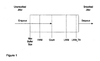
- Figure 1 shows an adaptive jitter buffer according to the present invention, for enqueueing data packets that have been subjected to unsmoothed jitter and dequeueing the data at a steady rate so that the dequeued data is subjected to smoothed jitter.
- the total number of packets capable of being stored in the buffer is represented by the maximum buffer size, while the minimum number of packets is LWM_TH.
- the "count” gives the number of packets in the buffer at any time, while the low water mark (LWM) indicates how far the buffer is away from underflow, and the high water mark (HWM) tracks the delay within the buffer.
- LWM low water mark
- HWM high water mark
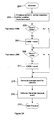
- an Enqueue event is initiated (step 201 of Figure 2A ).
- the received packet is loaded into the buffer in correct sequence number position, and "count” is incremented to reflect the current number of packets (step 203).
- HWM is set to count (step 205). If the count does not exceed HWM, or after step 205, a determination is made as to whether count is less than LWM (step 209). If it is, then LWM is set to count (step 211). If count is not less than LWM, or after step 211, the average count is computed for statistics purposes (step 213).
- a dequeue event ( Figure 2B ) is generated (step 215), and the Enqueue process ends (step 217).
- the Enqueue event may be implemented in software as follows:
- a Dequeue event ( Figure 2B ) may be generated after each Enqueue (step 215), and is generated in any event each Dequeue Time Tick (e.g. 20 ms).
- the current Dequeue TimeStamp (msCurrent) is obtained and the difference (msDiff) between the current and previous TimeStamps is calculated, representing the time since the last Dequeue event (step 221).
- msDiff is greater than the Dequeue Time Tick
- a predetermined time period e.g. 2s
- step 233 If yes, then if LWM exceeds LWM_TH (step 233), then a DequeueBuffer event is generated and a shrink counter is incremented (step 235). Next, or if LWM does not exceed LWM_TH, then the watermarks are re-initialized to the count value and a Shrink timestamp is updated (step 237).
- step 239 a determination is made (step 239) as to whether the buffer is overflowing (i.e. count>max buffer size). If yes, a DequeueBuffer event is generated and an Overflow Counter is incremented (step 241)
- step 243 the Dequeue event ends (step 243).
- the Dequeue event may be implemented in software as follows: Dequeue
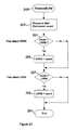
- the DequeueBuffer event ( Figure 2C ) governs the unloading of packets from the buffer. Following instantiation of the DequeueBuffer event (step 245), the data packets or dequeued from the buffer and count is decremented accordingly (step 247).
- HWM is set to count (step 253). If not, and in any event after step 253, a determination is made (step 257) as to whether count is less than LWM. If yes, then LWM is set to count. If count is not less than LWM, and in any event after step 253, then the DequeueBuffer event ends (step 261).
- the Dequeue event may be implemented in software as follows:
- the algorithm for controlling enqueueing and dequeueing of data packets minimizes the delay within the buffer by using a quick 'attack', at the expense of preventing buffer underflow. Since it is very difficult to predict network behavior, control of the buffer is biased towards introducing a minimum delay by adapting quickly to large jitter events and by inserting additional packets using packet loss concealment during buffer underflow. After a large jitter event, the buffer contains several packets and the delay introduced by the buffer is equivalent to the jitter length. When network conditions normalize, the delay within the buffer is far larger than is required (i.e. the actual current jitter is smaller than the buffer delay). The buffer is drained slowly (at the slip or drain rate, currently set at 2s). Consequently, control of the buffer is characterized by a slow decay time.
- FIG 3 shows typical behaviour of the buffer under the enqueue and dequeue control algorithms of Figure 2 , including adjustment of watermark levels over time.
- the draining of data occurs at the drain rate when count exceeds LWM.
- the high water mark (HWM) is tracked for statistics purposes only, and is not used to control the buffer.
- the number of packets (count) is averaged within the Enqueue event and the watermarks are adjusted relative to this average value. Specifically, the LWM is adjusted upwardly if the average count exceeds LWM, and the high water mark is adjusted downwardly if the average count is less than HWM. In other words, the watermarks decay towards the average count in the buffer.
- the decay adjustment may be performed during the Dequeue event, on every slip adjust event, in which case no average count is calculated.
- drain strategies can be used than as set forth herein. For example, a faster drain rate may be used when the delay within the buffer is long and a slower rate used when the delay is short. Also, since the high water mark is an indication of the delay within the buffer, it can be used as well in controlling the buffer.
Landscapes
- Engineering & Computer Science (AREA)
- Computer Networks & Wireless Communication (AREA)
- Signal Processing (AREA)
- Data Exchanges In Wide-Area Networks (AREA)
Description
- The present invention relates generally to digital transmission systems, and more particularly to a method for reducing perceived network jitter by varying the amount of delay induced by a jitter buffer in a packet network.
- In packet-switched voice communication, maximum voice quality is achieved when voice packets arrive in the order that they were transmitted, at the exact rate that they are transmitted, and with the shortest possible transmission delay. However, the nature of data transmission in packet-switched or IP networks inherently gives rise to transmission delays (i.e. jitter) that may vary widely due to available bandwidth, number of nodes traversed by the packets, network congestion, etc. Packets can also be duplicated by network switching equipment or dropped. In addition, as a consequence of packet routing policies that are commonly employed, it is also possible for packets to arrive at an endpoint in a different order than they were transmitted.
- It is known in the art to use data buffers when receiving voice packets, to ameliorate the effects of network jitter. For example,
US Patent No. 6,603,749 , entitled Adaptive Buffer Management for Voice Over Packet network, by Andre Moskal and Andre Diorio, discloses a fixed length adaptive buffer, wherein the length of the buffer is a compromise between introduced delay and induced packet loss due to underflow or overflow. The fixed length adaptive buffer is effective on well-conditioned networks. However, on less well managed networks (e.g. jitter greater than 40 ms) such as the Internet, the jitter often exceeds the size of the buffer. Consequently, the buffer actually introduces additional packet loss. - Accordingly, much research has centered on methods that dynamically adapt the buffer length according to current network conditions. Dynamic jitter buffers reduce the effects of variable transmission delay by introducing additional delay at the packet receiver. This has the benefit of requiring no special consideration at the packet transmitter. Dynamic jitter buffers reduce perceived network jitter by varying the amount of delay induced by the jitter buffer according to detected changes in network transmission delay.
- Several approaches in the literature use adaptation to dynamically adjust the buffer to current changes in network delay. Adaptation techniques include LMS, neural networks, and fuzzy logic. Other methods use state machines, as set forth in Dynamic Jitter Buffering for Voice-Over-IP and Other Packet-Based Communication Systems (
US Patent Application No. 2003026275 ). Unfortunately, these tend to suffer from implementation complexities. - Other examples of prior methods for managing jitter buffers are disclosed in
US 2003/0091047 A1 , in which packet delay variation is estimated, based on high and low watermarks in the depth of a jitter absorption buffer and used to adjust the performance of the jitter absorption buffer, andUS 6,658,027 B1 , in which frames meeting specific criteria are deleted from a jitter buffer if a high water mark is exceeded and a silence frame is inserted if the jitter buffer is depleted beyond a low water mark. - According to the present invention, a method of controlling a buffer for reducing jitter in a packet network comprises:
- a) receiving packets into said buffer;
- b) draining packets from said buffer;
- c) maintaining a count value of packets in said buffer;
- d) maintaining at least a low watermark value representing a minimum of said count value over a time period;
- e) once within each said time period setting said low watermark value equal to said count value;
- f) maintaining a high watermark value representing a maximum of said count value over said time period; and
- g) setting said high watermark value equal to said count value simultaneously with setting said low watermark value equal to said count value;
- i) obtaining a current Dequeue TimeStamp;
- ii) calculating the difference between the current Dequeue TimeStamp and a previous Dequeue TimeStamp;
- iii) if the difference is greater than a first predetermined time period, determining whether the buffer is empty then, if the buffer is not empty, generating a DequeueBuffer event and updating both the difference and Dequeue Time Stamp;
- iv) if the buffer is empty, inserting data by invoking packet loss concealment and updating the Dequeue Time Stamp;
- v) following step iv) or if the difference is not greater than the first predetermined time period, determining whether a second predetermined time period has elapsed since step e) was previously performed;
- vi) if said second predetermined time period has elapsed, then if said low watermark exceeds a low watermark threshold, generating a DequeueBuffer event and incrementing a second count value;
- vii) if said second predetermined time period has elapsed and said low watermark does not exceed said low watermark threshold and, then setting said high watermark and said low watermark to said count value; and
- viii) following step vii) or if said second predetermined time period has not yet elapsed, determining whether the buffer is overflowing and, if the buffer is overflowing, generating a DequeueBuffer event;
- The invention also provides a digital transmission system comprising a jitter buffer for a packet network, configured to control the jitter buffer by performing such a method.
- In this manner, a simple, state-less adaptation control algorithm can be provided, with a fast attack and a slow decay time to track delay changes in the network. The principal function of the algorithm for controlling the jitter buffer is to minimize the delay within the buffer (at the expense of occasional buffer underflow). Traditionally, jitter buffers attempt to smooth out jitter by preventing underflow, whereas minimizing the delay within the buffer is a secondary consideration. Although such prior art buffers prevent more underflow errors than the system of the present invention, they tend to introduce longer delays. For example, the fixed buffer discussed above in connection with
U.S. Patent Application No. 6,603,749 , is an example of a buffer control algorithm that maintains an average midpoint within the buffer. - An embodiment of the present invention will now be described, by way of example only, with reference to the attached Figures, wherein:
-
Figure 1 is a schematic representation of an adaptive jitter buffer according to the present invention; -
Figures 2A ,2B and2C are flowcharts showing steps for enqueueing and dequeueing data into and out of the jitter buffer ofFigure 1 , including adjustment of watermark levels governing the rate of dequeueing data based on network conditions, according to the present invention; and -
Figure 3 is a diagram showing an example of the buffer contents over time, including the adjustment of watermark levels, according to the present invention. -
Figure 1 shows an adaptive jitter buffer according to the present invention, for enqueueing data packets that have been subjected to unsmoothed jitter and dequeueing the data at a steady rate so that the dequeued data is subjected to smoothed jitter. The total number of packets capable of being stored in the buffer is represented by the maximum buffer size, while the minimum number of packets is LWM_TH. The "count" gives the number of packets in the buffer at any time, while the low water mark (LWM) indicates how far the buffer is away from underflow, and the high water mark (HWM) tracks the delay within the buffer. - Turning to
Figure 2 , upon receipt of a data packet an Enqueue event is initiated (step 201 ofFigure 2A ). The received packet is loaded into the buffer in correct sequence number position, and "count" is incremented to reflect the current number of packets (step 203). - If count exceeds HWM then HWM is set to count (step 205). If the count does not exceed HWM, or after
step 205, a determination is made as to whether count is less than LWM (step 209). If it is, then LWM is set to count (step 211). If count is not less than LWM, or afterstep 211, the average count is computed for statistics purposes (step 213). - Optionally, a dequeue event (
Figure 2B ) is generated (step 215), and the Enqueue process ends (step 217). - The Enqueue event may be implemented in software as follows:
     Enqueue
   For every packet
       Enqueue packet in correct seq num position
       Increment count // number of packets in queue

       /* Adjust watermarks, if required (fast attack) */
       IF count > HWM
           HWM = count // adjust HWM
       ENDIF

       IF count < LWM
           LWM = count
       ENDIF

       Average current count in buffer
   ENDFOR
    FOR every enqueue or 20ms tick // JB dequeue triggered
        Get current time stamp
        Calculate time difference (msDiff) since last dequeue
        WHILE msDiff > 20ms
            DequeueBuffer
            IF queue empty,
               Save current dequeue time
               Increment underflow counter
               break out
            END
            msDiff = msDiff - 20ms
            Update current dequeue time
        END WHILE

        // Check whether we have to slip adjust or are still in
    overflow
        FOR every jitter_Q_shrink_rate (currently 2s) time event
            IF LWM > LWM_TH (currently 1) (slow drain, deacy)
               DequeueBuffer // dequeue another packet, slip adjust
                   Increment shrink counter
            ENDIF

            /* Re-initialize watermarks */
            LWM = count
            HWM = count

            Update shrink Timestamp
        ENDFOR

        IF num of packets > Jitter size // Overflow checked on
     every enqueue and dequeue tick
            DequeueBuffer // Dequeue another packet
            Increment overflow counter
        ENDIF
     ENDFOR
   DequeueBuffer
    BEGIN
       Dequeue data
       Decrement count // number of packets in queue

       /* Adjust watermarks, if required (fast attack) */
       IF count > HWM
           HWM = count // adjust HWM
       ENDIF

       IF count < LWM
           LWM = count
       ENDIF
    END
Claims (2)
- A method of controlling a buffer for reducing jitter in a packet network comprising:a) receiving packets into said buffer;b) draining packets from said buffer;c) maintaining a count value of packets in said buffer;d) maintaining at least a low watermark value representing a minimum of said count value over a time period;e) once within each said time period setting said low watermark value equal to said count value (237);f) maintaining a high watermark value representing a maximum of said count value over said time period; andg) setting said high watermark value equal to said count value simultaneously with setting said low watermark value equal to said count value (237);wherein said receiving comprises, for each packet, loading the packet into said buffer in correct sequence number position (203), incrementing said count value (203), if the count value exceeds the high watermark value then setting said high watermark value to said count value (205, 207), and if said count value is less than the low watermark value then setting said low watermark value to said count value (209, 211);
characterized by:said draining comprising:wherein said DequeueBuffer event comprises, for each packet to be dequeued, dequeueing said packet from the buffer (247) and decrementing said count value, and if the count value exceeds the high watermark value then setting the high watermark value to the count value (251, 253), and if the count value is less than said low watermark value then setting the low watermark value to the count value (257, 259).i) obtaining a current Dequeue TimeStamp (221);ii) calculating the difference between the current Dequeue TimeStamp and a previous Dequeue TimeStamp (221);iii) if the difference is greater than a first predetermined time period, determining whether the buffer is empty (223, 225) and, if the buffer is not empty, generating a DequeueBuffer event and updating both the difference and Dequeue Time Stamp (227);iv) if the buffer is empty, inserting data by invoking packet loss concealment and updating the Dequeue Time Stamp (229);v) following step iv) or if the difference is not greater than the first predetermined time period, determining whether a second predetermined time period has elapsed since step e) was previously performed (231);vi) if said second predetermined time period has elapsed, then if said low watermark exceeds a low watermark threshold, generating a DequeueBuffer event and incrementing a second count value (233, 235);vii) if said second predetermined time period has elapsed and said low watermark does not exceed said low watermark threshold, then setting said high watermark and said low watermark to said count value (237); andviii) following step vii) or if said second predetermined time period has not yet elapsed, determining whether the buffer is overflowing and, if the buffer is overflowing, generating a DequeueBuffer event (239, 241); - A digital transmission system comprising a jitter buffer for a packet network, configured to control the jitter buffer by performing a method according to claim 1.
Applications Claiming Priority (2)
| Application Number | Priority Date | Filing Date | Title |
|---|---|---|---|
| CA2457812 | 2004-02-16 | ||
| CA2457812A CA2457812C (en) | 2004-02-16 | 2004-02-16 | Method of dynamic adaptation for jitter buffering in packet networks |
Publications (3)
| Publication Number | Publication Date |
|---|---|
| EP1564935A2 EP1564935A2 (en) | 2005-08-17 |
| EP1564935A3 EP1564935A3 (en) | 2008-09-17 |
| EP1564935B1 true EP1564935B1 (en) | 2011-10-26 |
Family
ID=34683100
Family Applications (1)
| Application Number | Title | Priority Date | Filing Date |
|---|---|---|---|
| EP04102763A Expired - Lifetime EP1564935B1 (en) | 2004-02-16 | 2004-06-16 | Method of dynamic adaptation for jitter buffering in packet networks |
Country Status (2)
| Country | Link |
|---|---|
| EP (1) | EP1564935B1 (en) |
| CA (1) | CA2457812C (en) |
Families Citing this family (4)
| Publication number | Priority date | Publication date | Assignee | Title |
|---|---|---|---|---|
| CN1960315B (en) * | 2005-10-31 | 2010-08-25 | 康佳集团股份有限公司 | Streaming Media Dejitter Method |
| EP1931068A1 (en) * | 2006-12-04 | 2008-06-11 | Nokia Siemens Networks Gmbh & Co. Kg | Method of adaptively dejittering packetized signals buffered at the receiver of a communication network node |
| CN105099795A (en) | 2014-04-15 | 2015-11-25 | 杜比实验室特许公司 | Jitter buffer level estimation |
| US11876735B1 (en) | 2023-04-21 | 2024-01-16 | Cisco Technology, Inc. | System and method to perform lossless data packet transmissions |
Family Cites Families (3)
| Publication number | Priority date | Publication date | Assignee | Title |
|---|---|---|---|---|
| DE69803574T2 (en) | 1998-10-27 | 2002-08-29 | Robert Bosch Gmbh | Method for estimating the channel impulse response of a signal transmission channel and mobile station |
| US6658027B1 (en) * | 1999-08-16 | 2003-12-02 | Nortel Networks Limited | Jitter buffer management |
| US6728209B2 (en) * | 2001-07-25 | 2004-04-27 | Overture Networks, Inc. | Measurement of packet delay variation |
-
2004
- 2004-02-16 CA CA2457812A patent/CA2457812C/en not_active Expired - Lifetime
- 2004-06-16 EP EP04102763A patent/EP1564935B1/en not_active Expired - Lifetime
Also Published As
| Publication number | Publication date |
|---|---|
| CA2457812A1 (en) | 2005-08-16 |
| EP1564935A3 (en) | 2008-09-17 |
| EP1564935A2 (en) | 2005-08-17 |
| CA2457812C (en) | 2011-10-11 |
Similar Documents
| Publication | Publication Date | Title |
|---|---|---|
| US7573894B2 (en) | Method of dynamic adaptation for jitter buffering in packet networks | |
| EP2235894B1 (en) | A simple adaptive jitter buffering algorithm for network nodes | |
| US7079486B2 (en) | Adaptive threshold based jitter buffer management for packetized data | |
| Johansson et al. | Self-clocked rate adaptation for multimedia | |
| AU686225B2 (en) | Method for adaptive smoothing delay for packet voice applications | |
| US7263109B2 (en) | Clock skew compensation for a jitter buffer | |
| EP1278353B1 (en) | Dynamic jitter buffering for voice-over-ip and other packet-based communication systems | |
| US6658027B1 (en) | Jitter buffer management | |
| EP2380294B1 (en) | Method for controlling a flow in a packet switching network | |
| US20030086372A1 (en) | Automatic adjustment of buffer depth for the correction of packet delay variation | |
| US7936672B2 (en) | System and method for buffer management in a packet-based network | |
| WO2005101744A2 (en) | Network delay control | |
| US20050207342A1 (en) | Communication terminal device, communication terminal receiving method, communication system and gateway | |
| JP2002009842A (en) | Automatic adaptive jitter buffer | |
| WO2008068167A1 (en) | Method of adaptively dejittering packetized signals buffered at the receiver of a communication network node | |
| CN111726301B (en) | Congestion control method and system for ensuring video quality in real-time video | |
| US6912224B1 (en) | Adaptive playout buffer and method for improved data communication | |
| CA2457812C (en) | Method of dynamic adaptation for jitter buffering in packet networks | |
| JP3548005B2 (en) | Flow control method and flow control device | |
| EP2009820B1 (en) | Method and receiver for determining a jitter buffer level | |
| Ye et al. | Receiver-buffer-driven approach to adaptive Internet video streaming | |
| Johansson et al. | RFC 8298: Self-Clocked Rate Adaptation for Multimedia | |
| Choudhury et al. | Design and analysis of optimal adaptive de-jitter buffers | |
| HK1132394B (en) | Network delay control |
Legal Events
| Date | Code | Title | Description |
|---|---|---|---|
| PUAI | Public reference made under article 153(3) epc to a published international application that has entered the european phase |
Free format text: ORIGINAL CODE: 0009012 |
|
| AK | Designated contracting states |
Kind code of ref document: A2 Designated state(s): AT BE BG CH CY CZ DE DK EE ES FI FR GB GR HU IE IT LI LU MC NL PL PT RO SE SI SK TR |
|
| AX | Request for extension of the european patent |
Extension state: AL HR LT LV MK |
|
| PUAL | Search report despatched |
Free format text: ORIGINAL CODE: 0009013 |
|
| AK | Designated contracting states |
Kind code of ref document: A3 Designated state(s): AT BE BG CH CY CZ DE DK EE ES FI FR GB GR HU IE IT LI LU MC NL PL PT RO SE SI SK TR |
|
| AX | Request for extension of the european patent |
Extension state: AL HR LT LV MK |
|
| 17P | Request for examination filed |
Effective date: 20090225 |
|
| AKX | Designation fees paid |
Designated state(s): DE FR GB |
|
| 17Q | First examination report despatched |
Effective date: 20091021 |
|
| GRAP | Despatch of communication of intention to grant a patent |
Free format text: ORIGINAL CODE: EPIDOSNIGR1 |
|
| GRAS | Grant fee paid |
Free format text: ORIGINAL CODE: EPIDOSNIGR3 |
|
| GRAA | (expected) grant |
Free format text: ORIGINAL CODE: 0009210 |
|
| AK | Designated contracting states |
Kind code of ref document: B1 Designated state(s): DE FR GB |
|
| REG | Reference to a national code |
Ref country code: GB Ref legal event code: FG4D |
|
| RIN2 | Information on inventor provided after grant (corrected) |
Inventor name: DILKIE, LEE Inventor name: SCHULTZ, DIETER |
|
| REG | Reference to a national code |
Ref country code: DE Ref legal event code: R096 Ref document number: 602004034988 Country of ref document: DE Effective date: 20111229 |
|
| PLBE | No opposition filed within time limit |
Free format text: ORIGINAL CODE: 0009261 |
|
| STAA | Information on the status of an ep patent application or granted ep patent |
Free format text: STATUS: NO OPPOSITION FILED WITHIN TIME LIMIT |
|
| 26N | No opposition filed |
Effective date: 20120727 |
|
| REG | Reference to a national code |
Ref country code: DE Ref legal event code: R097 Ref document number: 602004034988 Country of ref document: DE Effective date: 20120727 |
|
| REG | Reference to a national code |
Ref country code: FR Ref legal event code: PLFP Year of fee payment: 13 |
|
| REG | Reference to a national code |
Ref country code: FR Ref legal event code: PLFP Year of fee payment: 14 |
|
| REG | Reference to a national code |
Ref country code: FR Ref legal event code: PLFP Year of fee payment: 15 |
|
| REG | Reference to a national code |
Ref country code: FR Ref legal event code: PLFP Year of fee payment: 20 |
|
| PGFP | Annual fee paid to national office [announced via postgrant information from national office to epo] |
Ref country code: FR Payment date: 20230411 Year of fee payment: 20 Ref country code: DE Payment date: 20230418 Year of fee payment: 20 |
|
| PGFP | Annual fee paid to national office [announced via postgrant information from national office to epo] |
Ref country code: GB Payment date: 20230427 Year of fee payment: 20 |
|
| REG | Reference to a national code |
Ref country code: DE Ref legal event code: R071 Ref document number: 602004034988 Country of ref document: DE |
|
| PG25 | Lapsed in a contracting state [announced via postgrant information from national office to epo] |
Ref country code: GB Free format text: LAPSE BECAUSE OF EXPIRATION OF PROTECTION Effective date: 20240615 |
|
| PG25 | Lapsed in a contracting state [announced via postgrant information from national office to epo] |
Ref country code: GB Free format text: LAPSE BECAUSE OF EXPIRATION OF PROTECTION Effective date: 20240615 |