EP1564572A1 - Optical multiplexer/demultiplexer and production method for optical multiplexer/demultiplexer - Google Patents
Optical multiplexer/demultiplexer and production method for optical multiplexer/demultiplexer Download PDFInfo
- Publication number
- EP1564572A1 EP1564572A1 EP03770004A EP03770004A EP1564572A1 EP 1564572 A1 EP1564572 A1 EP 1564572A1 EP 03770004 A EP03770004 A EP 03770004A EP 03770004 A EP03770004 A EP 03770004A EP 1564572 A1 EP1564572 A1 EP 1564572A1
- Authority
- EP
- European Patent Office
- Prior art keywords
- light
- optical
- wavelengths
- wavelength selecting
- selecting elements
- Prior art date
- Legal status (The legal status is an assumption and is not a legal conclusion. Google has not performed a legal analysis and makes no representation as to the accuracy of the status listed.)
- Withdrawn
Links
Images

















Classifications
-
- G—PHYSICS
- G02—OPTICS
- G02B—OPTICAL ELEMENTS, SYSTEMS OR APPARATUS
- G02B6/00—Light guides; Structural details of arrangements comprising light guides and other optical elements, e.g. couplings
- G02B6/24—Coupling light guides
- G02B6/26—Optical coupling means
- G02B6/28—Optical coupling means having data bus means, i.e. plural waveguides interconnected and providing an inherently bidirectional system by mixing and splitting signals
- G02B6/293—Optical coupling means having data bus means, i.e. plural waveguides interconnected and providing an inherently bidirectional system by mixing and splitting signals with wavelength selective means
- G02B6/29379—Optical coupling means having data bus means, i.e. plural waveguides interconnected and providing an inherently bidirectional system by mixing and splitting signals with wavelength selective means characterised by the function or use of the complete device
- G02B6/2938—Optical coupling means having data bus means, i.e. plural waveguides interconnected and providing an inherently bidirectional system by mixing and splitting signals with wavelength selective means characterised by the function or use of the complete device for multiplexing or demultiplexing, i.e. combining or separating wavelengths, e.g. 1xN, NxM
-
- G—PHYSICS
- G02—OPTICS
- G02B—OPTICAL ELEMENTS, SYSTEMS OR APPARATUS
- G02B1/00—Optical elements characterised by the material of which they are made; Optical coatings for optical elements
- G02B1/10—Optical coatings produced by application to, or surface treatment of, optical elements
- G02B1/11—Anti-reflection coatings
-
- G—PHYSICS
- G02—OPTICS
- G02B—OPTICAL ELEMENTS, SYSTEMS OR APPARATUS
- G02B6/00—Light guides; Structural details of arrangements comprising light guides and other optical elements, e.g. couplings
- G02B6/24—Coupling light guides
- G02B6/26—Optical coupling means
- G02B6/28—Optical coupling means having data bus means, i.e. plural waveguides interconnected and providing an inherently bidirectional system by mixing and splitting signals
- G02B6/293—Optical coupling means having data bus means, i.e. plural waveguides interconnected and providing an inherently bidirectional system by mixing and splitting signals with wavelength selective means
- G02B6/29346—Optical coupling means having data bus means, i.e. plural waveguides interconnected and providing an inherently bidirectional system by mixing and splitting signals with wavelength selective means operating by wave or beam interference
- G02B6/29361—Interference filters, e.g. multilayer coatings, thin film filters, dichroic splitters or mirrors based on multilayers, WDM filters
- G02B6/29362—Serial cascade of filters or filtering operations, e.g. for a large number of channels
- G02B6/29365—Serial cascade of filters or filtering operations, e.g. for a large number of channels in a multireflection configuration, i.e. beam following a zigzag path between filters or filtering operations
- G02B6/29367—Zigzag path within a transparent optical block, e.g. filter deposited on an etalon, glass plate, wedge acting as a stable spacer
-
- G—PHYSICS
- G02—OPTICS
- G02B—OPTICAL ELEMENTS, SYSTEMS OR APPARATUS
- G02B6/00—Light guides; Structural details of arrangements comprising light guides and other optical elements, e.g. couplings
- G02B6/24—Coupling light guides
- G02B6/26—Optical coupling means
- G02B6/32—Optical coupling means having lens focusing means positioned between opposed fibre ends
-
- G—PHYSICS
- G02—OPTICS
- G02B—OPTICAL ELEMENTS, SYSTEMS OR APPARATUS
- G02B6/00—Light guides; Structural details of arrangements comprising light guides and other optical elements, e.g. couplings
- G02B6/24—Coupling light guides
- G02B6/36—Mechanical coupling means
- G02B6/38—Mechanical coupling means having fibre to fibre mating means
- G02B6/3807—Dismountable connectors, i.e. comprising plugs
- G02B6/381—Dismountable connectors, i.e. comprising plugs of the ferrule type, e.g. fibre ends embedded in ferrules, connecting a pair of fibres
-
- G—PHYSICS
- G02—OPTICS
- G02B—OPTICAL ELEMENTS, SYSTEMS OR APPARATUS
- G02B6/00—Light guides; Structural details of arrangements comprising light guides and other optical elements, e.g. couplings
- G02B6/24—Coupling light guides
- G02B6/36—Mechanical coupling means
- G02B6/38—Mechanical coupling means having fibre to fibre mating means
- G02B6/3807—Dismountable connectors, i.e. comprising plugs
- G02B6/3897—Connectors fixed to housings, casing, frames or circuit boards
-
- G—PHYSICS
- G02—OPTICS
- G02B—OPTICAL ELEMENTS, SYSTEMS OR APPARATUS
- G02B6/00—Light guides; Structural details of arrangements comprising light guides and other optical elements, e.g. couplings
- G02B6/24—Coupling light guides
- G02B6/42—Coupling light guides with opto-electronic elements
-
- G—PHYSICS
- G02—OPTICS
- G02B—OPTICAL ELEMENTS, SYSTEMS OR APPARATUS
- G02B6/00—Light guides; Structural details of arrangements comprising light guides and other optical elements, e.g. couplings
- G02B6/10—Light guides; Structural details of arrangements comprising light guides and other optical elements, e.g. couplings of the optical waveguide type
- G02B6/12—Light guides; Structural details of arrangements comprising light guides and other optical elements, e.g. couplings of the optical waveguide type of the integrated circuit kind
- G02B2006/12083—Constructional arrangements
- G02B2006/12102—Lens
-
- G—PHYSICS
- G02—OPTICS
- G02B—OPTICAL ELEMENTS, SYSTEMS OR APPARATUS
- G02B6/00—Light guides; Structural details of arrangements comprising light guides and other optical elements, e.g. couplings
- G02B6/10—Light guides; Structural details of arrangements comprising light guides and other optical elements, e.g. couplings of the optical waveguide type
- G02B6/12—Light guides; Structural details of arrangements comprising light guides and other optical elements, e.g. couplings of the optical waveguide type of the integrated circuit kind
- G02B2006/12083—Constructional arrangements
- G02B2006/12114—Prism
-
- G—PHYSICS
- G02—OPTICS
- G02B—OPTICAL ELEMENTS, SYSTEMS OR APPARATUS
- G02B6/00—Light guides; Structural details of arrangements comprising light guides and other optical elements, e.g. couplings
- G02B6/10—Light guides; Structural details of arrangements comprising light guides and other optical elements, e.g. couplings of the optical waveguide type
- G02B6/12—Light guides; Structural details of arrangements comprising light guides and other optical elements, e.g. couplings of the optical waveguide type of the integrated circuit kind
- G02B2006/12133—Functions
- G02B2006/12164—Multiplexing; Demultiplexing
Definitions
- the present invention relates to a compact optical multiplexer/demultiplexer with multiple channels, and to a manufacturing method for such an optical multiplexer/demultiplexer.
- optical communications that use optical fiber cables as a signal transmission medium have been developed up to a level where optical communications can be utilized in residential homes, and a communications network has been expanded.
- a wavelength multiplexing transmission system for multiplexing optical signals having different wavelengths so as to transmit the resulting signal through a single optical fiber is utilized.
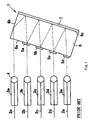
- FIG. 1 is a schematic side diagram showing the configuration of an optical demultiplexer 1 according to the prior art (see Japanese Published Unexamined Patent Application S60-184215).
- Optical demultiplexer 1 shown in FIG. 1 is formed of five collimators 3a, 3b, 3c, 3d and 3e, where ball lenses 4 and optical fibers 2a, 2b, 2c, 2d and 2e are integrated and aligned in parallel, a glass body 6 having two surfaces 6a and 6c that are parallel to each other and a surface 6b that is perpendicular to these, interference film filters 5a, 5b, 5c and 5d which are placed in parallel on surface 6a of glass body 6 and transmit only light in bandwidths of particular wavelengths ⁇ 1, ⁇ 2, ⁇ 3 and ⁇ 4, respectively, and a reflective mirror 7 that is made to adhere to surface 6c of glass body 6.
- a light beam (light where wavelengths ⁇ 1, ⁇ 2, ⁇ 3 and ⁇ 4 have been multiplexed) that has been emitted from collimator 3a and has entered into glass body 6 is totally reflected from surface 6b of glass body 6, and furthermore, is totally reflected from surface 6c (reflective mirror 7) so as to enter into interference film filter 5a.
- Light having wavelength ⁇ 1 that has transmitted through this interference film filter 5a enters into collimator 3b, and therefore, light having wavelength ⁇ 1 can be taken out from the light emitting end of optical fiber 2b.
- interference film filter 5a light having wavelengths ⁇ 2, ⁇ 3 and ⁇ 4 that has been reflected from interference film filter 5a is furthermore totally reflected from reflective mirror 7, and enters into interference film filter 5b, so that light having wavelength ⁇ 2 that has transmitted through interference film filter 5b enters into collimator 3c.
- reflection is repeated by interference film filters 5a, 5b and 5c and reflective mirror 7 while demultiplexing is being carried out, and thereby, light having wavelengths ⁇ 1, ⁇ 2, ⁇ 3 and ⁇ 4 that has transmitted through interference film filters 5a, 5b, 5c and 5d can be taken out from the light emitting ends of optical fibers 2b, 2c, 2d and 2e, respectively.
- optical demultiplexer 1 shown in FIG. 1 however, light that has been emitted from collimator 3a must be made to enter diagonally into surface 6a of glass body 6, and therefore, the more the number of wavelengths to be demultiplexed (or the number of optical fibers) increases, the greater the distance between collimator 3a and surface 6a of the glass body becomes, and thus, a problem arises where optical demultiplexer 1 increases in size.
- the manufacturing process that includes setting of positions where collimators 3a to 3e and glass body 6 are installed, precise adhesion of a number of interference film filters 5a to 5d to glass body 6 one by one, and the formation of reflective mirror 7 on glass body 6 with high precision is complex, and therefore, efficiency in production cannot be increased, making it difficult to reduce cost.
- An object of the present invention is to provide a compact and inexpensive optical multiplexer/demultiplexer of a multiple channel type for demultiplexing light into multiple wavelengths or wavelength bands, or for multiplexing light having multiple wavelengths or wavelength bands, as well as to provide a manufacturing method for the same.
- a first optical multiplexer/demultiplexer In a first optical multiplexer/demultiplexer according to the present invention, plurality of wavelength selecting elements of which the transmission wavelength bands are different from each other and a light reflecting surface are made to face each other, and thereby, an optical guiding means for guiding light by making light being reflected between the light reflecting surface and the respective wavelength selecting elements and for multiplexing or demultiplexing light having different wavelengths is formed; a transmission means for transmitting light having plurality of wavelengths is coupled to light having plurality of wavelengths or wavelength bands that are guided within the above-described optical guiding means; plurality of light inputting/outputting means are placed on the same side as the above-described transmission means relative to the above-described optical guidingmeans in a manner where the direction of the optical axis becomes approximately perpendicular to the direction in which the above-described wavelength selecting elements are aligned; and a deflection element for converting the direction of the optical axis of light that has transmitted through each of the above-described
- an optical fiber or an optical wave guide for example, can be used as the transmission means.
- an optical fiber, an optical wave guide, a light emitting element, such as a semiconductor laser element, a light receiving element, such as a photodiode, or the like is used as the light inputting/outputting means.
- a filter, a diffraction element, such as a diffraction grating or a CGH element, or the like can be used for the wavelength selecting elements.
- the deflection elements may be formed of lenses which are not rotationally symmetrical around their center axes, spherical lenses, aspherical lenses or anamorphic lenses where the centers in the cross sections of transmitting light fluxes are shifted from the optical axes of these, or may be formed of prisms and lenses or mirrors and lenses.
- the direction of the optical axis of light means the direction in which light progresses passing through the center of the cross section of light flux.
- the deflection element that is provided between each of the light inputting and outputting means and each of the wavelength selecting elements is used to convert the optical axis of light that transmits through each wavelength selecting element into the optical axis of each light inputting and outputting means, or to convert the optical axis of each light inputting and outputting means into the optical axis of light that passes through each wavelength selecting element, and therefore, the plurality of light inputting and outputting means can be placed on the same side as the transmission means relative to the optical guiding means in a manner where the direction of the optical axis of the light inputting and outputting means becomes approximately perpendicular to the direction in which wavelength selecting elements are aligned. Accordingly, even in the case where plurality of the wavelengths or wavelength bands to be demultiplexed or multiplexed by the optical multiplexer/demultiplexer increases, the optical multiplexer/demultiplexer does not easily increase in size.
- an antireflection film is provided in the middle of the light path between the above-described transmission means and the above-described optical guiding means. Accordingly, at the time when the optical multiplexer/demultiplexer is used as a demultiplexer, loss of light that has been emitted from the transmission means due to reflection from the surface of the above-described optical guiding means can be reduced.
- This antireflection film may be placed in parallel to each of the above-described wavelength selecting elements in a manner where the surface of the antireflection film and the surface of each of the above-described wavelength selecting elements are in the same plane, or may be placed so as to overlap the filter.
- a second optical multiplexer/demultiplexer is provided with: an optical guiding means which is made of a light reflecting surface and plurality of wavelength selecting elements which are aligned in a plane that is parallel to the light reflecting surface, and of which the transmission wavelength bands are different from each other, which guides light by making light be reflected between the light reflecting surface and the respective wavelength selecting elements, and which multiplexes or demultiplexes light having different wavelengths; an optical fiber array where a first optical fiber for transmitting light having plurality of wavelengths or wavelength bands and plurality of second optical fibers for transmitting light having particular wavelengths or wavelength bands are aligned in a manner where the optical axis of each optical fiber becomes approximately perpendicular to the plane in which the above-described wavelength selecting elements are aligned; and one or more deflection element for bending the direction of the optical axis of transmitting light, which are placed so as to face the above-described first and second optical fibers, wherein the above-described first optical fiber is coupled to light having plurality
- a filter, a diffraction element, such as a diffraction grating or a CGH element, or the like can be used for the wavelength selecting elements.
- the deflection elements may be formed of lenses which are not rotationally symmetrical around their center axes, spherical lenses, aspherical lenses or anamorphic lenses where the center in the cross section of light flux that transmits through these is shifted from the optical axes of these, or may be formed of prisms and lenses or mirrors and lenses.
- the second optical multiplexer/demultiplexer In the second optical multiplexer/demultiplexer according to the present invention, light having plurality of wavelengths is transmitted through the first optical fiber so as to enter into a deflection element, and the direction of the optical axis of light is bent in the deflection element so that light is diagonally emitted to the optical guiding means, and then, light having respective wavelengths that has transmitted through the wavelength selecting elements while the light is being reflected from the wavelength selecting elements and the light reflecting surface of the above-described optical guiding means is made to enter into each of the above-described deflection elements, and light having different wavelengths that has transmitted through the deflection elements is made to enter into the respective second optical fibers so as to be transmitted, and thereby, demultiplexed light can be taken out.
- the second optical multiplexer/demultiplexer according to the present invention when used as a multiplexer, light having different wavelengths is transmitted respectively through the above-described second optical fibers so as to enter into the above-described deflection elements, and the light that has transmitted through the deflection elements are made to diagonally enter into the optical guiding means, where the light is multiplexed while being reflected from the light reflecting surface and the wavelength selecting elements, and then, the multiplexed light is transmitted through the above-described deflection elements so as to be bent and made to enter into the first optical fiber, and thereby, the multiplexed light can be taken out from the first optical fiber.
- the second optical multiplexer/demultiplexer according to the present invention is provided with an optical fiber array where first and second optical fibers are aligned in parallel, where the optical axis of the first optical fiber, in addition to those of the second optical fibers, are placed parallel to the above-described wavelength selecting elements, and therefore, the optical multiplexer/demultiplexer can further be miniaturized.
- the above-described deflection element of the second optical multiplexer/demultiplexer according to an embodiment of the present invention is joined to and integrated with an end of the above-described optical fiber array.
- the assembly of the optical multiplexer/demultiplexer becomes easy.
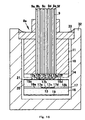
- the above-described optical guiding means, the above-described deflection element and the above-described optical fiber array are contained within a case so as to be sealed.
- the wavelength selecting elements which are, for example, filters, can be protected particularly from humidity, and thus, durability is increased.
- a third optical multiplexer/demultiplexer is provided with: an optical guiding means which is made of a light reflecting surface and plurality of wavelength selecting elements which are aligned in a plane that is parallel to the light reflecting surface, and of which the transmission wavelength bands are different from each other, which guides light by making light be reflected between the light reflecting surface and the respective wavelength selecting elements, and which multiplexes or demultiplexes light having different wavelengths; a transmission means for transmitting light having plurality of wavelengths of which the optical axis is placed so as to be approximately perpendicular to the plane in which the above-described wavelength selecting elements are aligned; plurality of light emitting elements for respectively outputting light having particular wavelengths of which the optical axes are placed so as to be approximately perpendicular to the plane in which the above-described wavelength selecting elements are aligned; and one or more deflection element for bending the direction of the optical axis of transmitting light which is placed so as to face the above-described transmission means and the above-de
- an optical fiber or an optical wave guide can be used as the transmission means.
- a filter, a diffraction element, such as a diffraction grating or a CGH element, or the like can be used for the wavelength selecting elements.
- the deflection elements may be formed of lenses which are not rotationally symmetrical around their center axes or rectilinear lenses where the center in the cross section of light flux that transmits through these is shifted from the optical axes of these, or may be formed of prisms and lenses or mirrors and lenses.
- the third optical multiplexer/demultiplexer In the third optical multiplexer/demultiplexer according to the present invention, light having different wavelengths is emitted from the light emitting element so as to enter into the above-described deflection element and the light that has transmitted through this deflection element and that has been bent is made to diagonally enter into the optical guiding means where the light is reflected from the light reflecting surface and the wavelength selecting elements while the light is multiplexed and this multiplexed light is made to transmit through the above-described deflection element so as to be bent and be made to enter the transmission means and the multiplexed light can be taken out from the transmission means.
- the transmission means and the respective light emitting elements can be aligned in parallel, and therefore, the optical axis of the transmission means in addition to the light emitting elements can be placed perpendicular to the above-described wavelength selecting elements and thus, the optical multiplexer/demultiplexer can miniaturized.
- a fourth optical multiplexer/demultiplexer is provided with: an optical guiding means which is made of a light reflecting surface and plurality of wavelength selecting elements which are aligned in a plane that is parallel to the light reflecting surface, and of which the transmission wavelengths are different from each other, which guides light by making light be reflected between the light reflecting surface and the respective wavelength selecting elements, and which multiplexes or demultiplexes light having different wavelengths; a transmission means for transmitting light having plurality of wavelengths of which the optical axis is placed so as to be approximately perpendicular to the plane in which the above-described wavelength selecting elements are aligned; plurality of light receiving elements of which the optical axes are placed so as to be approximately perpendicular to the plane in which the above-described wavelength selecting elements are aligned; and one or more deflection element for bending the direction of the optical axis of transmitting light which is placed so as to face the above-described transmission means and the above-described light receiving element, wherein the above-
- an optical fiber or an optical wave guide can be used as the transmission means.
- a filter, a diffraction element, such as a diffraction grating or a CGH element, or the like can be used for the wavelength selecting elements.
- the deflection elements may be formed of lenses which are not rotationally symmetrical around their center axes or rectilinear lenses where the center in the cross section of light flux that transmits through these is shifted from the optical axes of these, or may be formed of prisms and lenses or mirrors and lenses.
- the fourth optical multiplexer/demultiplexer In the fourth optical multiplexer/demultiplexer according to the present invention, light having plurality of wavelengths is transmitted through the above-described transmission means so as to enter into the above-described deflection element and the light is bent by the deflection element so as to be diagonally emitted toward the optical guiding means, and then, light having each wavelength that has transmitted through the wavelength selecting elements is demultiplexed while the light is made to be reflected from the wavelength selecting elements and the light reflecting surface of the above-described optical guiding means so that the light having each wavelength enters into the deflection element so as to be bent and the light that has transmitted through the deflection element is received by the respective light receiving elements so as to be transmitted, and thereby, the demultiplexed light can be taken out.
- the above-described transmission means and the light receiving elements can be aligned in parallel, and therefore, the optical axis of the transmission means in addition to the above-described light receiving elements can be placed so as to be perpendicular to the above-described wavelength selecting elements, and thus, the optical multiplexer/demultiplexer can be miniaturized.
- a fifth optical multiplexer/demultiplexer is provided with: an optical guiding means which is made of a light reflecting surface and plurality of wavelength selecting elements which are aligned in a plane that is parallel to the light reflecting surface, and of which the transmission wavelengths are different from each other, which guides light by making light be reflected between the light reflecting surface and the respective wavelength selecting elements and which multiplexes or demultiplexes light having different wavelengths; plurality of light inputting means of which the optical axes are placed so as to be approximately perpendicular to the plane in which the above-described wavelength selecting elements are aligned; a first transmission means for transmitting light having plurality of wavelengths which is placed in the direction in which the above-described wavelength selecting elements are aligned together with the above-described light inputting means in a manner where the optical axis becomes approximately perpendicular to the plane in which the above-described wavelength selecting elements are aligned; plurality of light outputtingmeans of which the optical axes are placed so as to be approximately
- an optical fiber or an optical wave guide can be used as the transmission means.
- An optical fiber, a semiconductor laser element, or the like can be used as the light inputting means.
- An optical fiber, a photodiode, or the like can be used as the light outputting means.
- a filter, a diffraction element, such as a diffraction grating or a CGH element, or the like can be used for the wavelength selecting elements.
- the deflection elements may be formed of lenses which are not rotationally symmetrical around their center axes or rectilinear lenses where the center in the cross section of light flux that transmits through these is shifted from the optical axes of these, or may be formed of prisms and lenses or mirrors and lenses.
- the fifth optical multiplexer/demultiplexer In the fifth optical multiplexer/demultiplexer according to the present invention, light that has been emitted from the above-described respective light inputting means is bent by the first deflection element so as to diagonally enter the optical guiding means and light having plurality of wavelengths that has been multiplexed by the optical guiding means is diagonally emitted from the optical guiding means, and then, light having plurality of wavelengths that has been emitted from the optical guiding means is bent by the first deflection element so as to be coupled to the first transmission means so that the multiplexed light having plurality of wavelengths can be transmitted through the first transmission means.
- light having plurality of wavelengths that has been transmitted through the second transmission means is emitted from the second transmission means and this light is bent by the second deflection element so as to diagonally enter into the optical guiding means, and then, light having each wavelength that has been demultiplexed by the optical guiding means is diagonally emitted from the optical guiding means and light having each wavelength that has been emitted from the optical guiding means is bent by the second deflection element so as to be received by the respective light outputting means.
- the light inputting means, the light outputting means and the first and second transmission means can be aligned in parallel and therefore, the respective optical axes of the light inputting means, the light outputting means and the first and second transmission means can be placed so as to be perpendicular to the above-described wavelength selecting elements, and thus, the optical multiplexer/demultiplexer can be miniaturized.
- the same wavelength selecting elements can be used on both the multiplexing side and on the demultiplexing side, and therefore, the structure of the optical multiplexer/demultiplexer can be simplified and the manufacturing process thereof can also be simplified.
- the above-described light having plurality of wavelengths and the above-described other light having plurality of wavelengths are light having plurality of same wavelengths, and the lengths of the light paths of the above-described light having plurality of wavelengths between the above-described second transmission means and the above-described light outputting means becomes shorter sequentially in the order from longest to shortest of the lengths of light paths between the above-described first transmission means and the above-described light inputting means.
- the two optical multiplexers/demultiplexers are connected in a manner where the second transmission means, which is one optical transmission means, and the first transmission means, which is the other optical transmission means, are connected, the length of the light path (transmission distance) between the two optical multiplexers/demultiplexers is equalized, irrespective of the wavelength of light, and therefore, it becomes difficult for dispersion to be caused in the insertion loss due to a difference in the wavelength.
- a sixth optical multiplexer/demultiplexer is provided with: an optical guiding means which is made of a light reflecting surface, plurality of first wavelength selecting elements which are aligned in a plane that is parallel to the light reflecting surface, and of which the transmission wavelengths are different from each other and plurality of second wavelength selecting elements which are aligned in a plane that is parallel to the light reflecting surface, and of which the transmission wavelengths are different from each other, which guides light by making the light be reflected between the light reflecting surface and the respective first wavelength selecting elements and multiplexes light having different wavelengths and which guides light by making the light be reflected between the light reflecting surface and the respective second wavelength selecting elements and demultiplexes light having different wavelengths; a transmission means for transmitting light having plurality of wavelengths; plurality of light inputting means which are placed in the direction in which the above-described first wavelength selecting elements are aligned in a manner wherein the optical axes become approximately perpendicular to the plane where the above-described first wavelength selecting elements are aligned
- an optical fiber or an optical wave guide can be used as the transmission means.
- An optical fiber, a semiconductor laser element, or the like can be used as the light inputting means.
- An optical fiber, a photodiode, or the like can be used as the light outputting means.
- a filter, a diffraction element, such as a diffraction grating or a CGH element, or the like can be used for the wavelength selecting elements.
- the deflection elements may be formed of lenses which are not rotationally symmetrical around their center axes or rectilinear lenses where the center in the cross section of light flux that transmits through these is shifted from the optical axes of these, or may be formed of prisms and lenses or mirrors and lenses.
- the sixth optical multiplexer/demultiplexer In the sixth optical multiplexer/demultiplexer according to the present invention, light that has been emitted from the above-described respective light inputting means is bent by the first deflection element so as to diagonally enter into the optical guiding means, the first wavelength selecting element emits light having plurality of wavelengths that has been multiplexed by the optical guiding means diagonally from the optical guiding means, and the light having plurality of wavelengths that has been emitted from the optical guiding means is bent by the first deflection element so as to be coupled to the transmission means, and thus, the multiplexed light having plurality of wavelengths can be transmitted through the transmission means.
- light having plurality of wavelengths that has been transmitted through the transmission means is emitted from the transmission means, this light is bent by the second deflection element so as to diagonally enter into the optical guiding means, and the second wavelength selecting element emits light having each wavelength that has been demultiplexed by the optical guiding means diagonally from the optical guiding means, and thus, the light having each wavelength that has been emitted from the optical guiding means can be bent by the second deflection element so as to be received by the respective light outputting means.
- the light inputting means, the light outputting means and the transmission means can be aligned in parallel, and therefore, the respective optical axes of the light inputting means, the light outputting means and the transmission means can be placed perpendicular to the above-described wavelength selecting elements, and the optical multiplexer/demultiplexer can be miniaturized.
- this optical multiplexer/demultiplexer can transmit and receive an optical signal through a single transmission means, and therefore, work at the time when the two optical multiplexers/demultiplexers are connected is simplified.
- the above-described light branching means is provided with: a filter for multiplexing and demultiplexing the above-described light having plurality of wavelengths that is sent from the above-described transmission means and the above-described other light having plurality of wavelengths that is sent from the above-described transmission means; and at least one light transferring means of a light transferring means such as an optical fiber, a core, a prism or a mirror for guiding light having plurality of wavelengths that has been multiplexed between the light reflecting surface of the above-described optical guiding means and the first wavelength selecting elements to the above-described transmission means, and a light transferring means such as an optical fiber, a core, a prism or a mirror for guiding the above-described other light having plurality of wavelengths that has been separated by the above-described filter to the second wavelength selecting elements of the optical guiding means.
- a light transferring means such as an optical fiber, a core, a prism or a mirror for guiding the above-described other
- an optical signal that is transmitted and received through a transmission means is separated by a filter, and after that, at least one of the separated optical signals can be guided to a desired place by using an optical transmission means, such as an optical fiber, a core, a prism or a mirror, and therefore, it becomes easily possible to use a single transmission means.
- an optical transmission means such as an optical fiber, a core, a prism or a mirror
- the above-described transmission means may be formed of an optical fiber
- the above-described light inputting means may be formed of light emitting elements
- the above-described light outputtingmeans maybe formed of light receiving elements.
- a transponder into which a light emitting element and a light receiving element are built in can be manufactured.
- a seventh optical multiplexer/demultiplexer is provided with: an optical guiding means which is made of a light reflecting surface and plurality of first wavelength selecting elements which are aligned in a plane that is parallel to the light reflecting surface, and of which the transmission wavelengths are different from each other, which guides light by making light be reflected between the light reflecting surface and the respective first wavelength selecting elements and which multiplexes light having different wavelengths; an optical guiding plate which is placed so as to face the surface of the above-described optical guiding means on the side opposite the light reflecting surface and so as to become approximately parallel to the above-described first wavelength selecting elements; a transmission means for transmitting light having plurality of wavelengths; plurality of light emitting elements which are placed on the above-described optical guiding plate in the direction in which the above-described first wavelength selecting elements are aligned in a manner where the optical axes of the light emitting elements are directed in the direction approximately perpendicular to the above-described optical guiding plate; a light receiving element which is placed on
- an optical fiber or an optical wave guide can be used as the transmission means.
- a filter, a diffraction element, such as a diffraction grating or a CGH element, or the like can be used for the wavelength selecting elements.
- the deflection elements may be formed of lenses which are not rotationally symmetrical around their center axes or rectilinear lenses where the center in the cross section of light flux that transmits through these is shifted from the optical axes of these, or may be formed of prisms and lenses or mirrors and lenses.
- the seventh optical multiplexer/demultiplexer In the seventh optical multiplexer/demultiplexer according to the present invention, light that has been emitted from the light emitting element is bent by the deflection element so as to diagonally enter into the optical guiding means, the first wavelength selecting element emits light having plurality of wavelengths that has been multiplexed by the optical guiding means diagonally from the optical guiding means, and the light having plurality of the wavelengths that has been emitted from the optical guiding means is coupled to the transmission means, and thus, the multiplexed light having plurality of the wavelengths can be transmitted through the transmission means.
- light having plurality of wavelengths that has been transmitted through the transmission means is outputted from the transmission means, this light is separated by the light branching means so as to be guided into the optical guiding plate, and light having each wavelength is demultiplexed by the second wavelength selecting element so as to be emitted from the optical guiding plate, and thus, the light having each wavelength that has been emitted from the optical guiding plate can be received by the light receiving element.
- the light inputting means and the light outputting means can be aligned on the optical guiding plate perpendicular to the optical guiding plate, and in addition, this optical multiplexer/demultiplexer guides light to the light receiving element by using the optical guiding plate, and therefore, the optical multiplexer/demultiplexer can be miniaturized.
- the above-described optical guiding means in embodiments of the first to seventh optical multiplexers/demultiplexers according to the present invention has the above-described respective wavelength selecting elements formed on the front surface of a transparent substrate and the above-described light reflecting surface formed on the rear surface of the above-described transparent substrate.
- the substrate that is used in the above-described optical guiding means is made of only one layer (one piece), and therefore, the optical guiding means can be made thin and the optical multiplexer/demultiplexer can be miniaturized.
- the above-described optical guiding means in other embodiments of the first to seventh optical multiplexers/demultiplexers according to the present invention has a transparent second substrate where the above-described plurality of wavelength selecting elements are aligned on the front surface joined to a transparent first substrate where the above-described light reflecting surface is formed on the rear surface.
- the first substrate and the second substrate are separately manufactured and joined by making the two adhere to each other with a transparent adhesive or the like, and therefore, the manufacture of the optical guiding means of the optical multiplexer/demultiplexer becomes easy.
- the above-described optical guiding means in still other embodiments of the first to seventh optical multiplexers/demultiplexers according to the present invention has plurality of transparent second substrates where the above-describedwavelength selecting elements are individually formed on the respective front surfaces aligned on and joined to a transparent first substrate where the above-described light reflecting surface is formed on the rear surface.
- the manufacturing process for the optical guiding means of the optical multiplexer/demultiplexer becomes easy.
- the above-described optical guiding means in yet other embodiments of the first to seventh optical multiplexers/demultiplexers according to the present invention has the above-described plurality of wavelength selecting elements formed between a pair of transparent substrates that overlap and has the above-described light reflecting surface formed on the rear surface of the substrate that is located on the rear surface side of the above-described substrates.
- the thicknesses of the two transparent substrates are adjusted, and thereby, the intervals between the first optical fiber and the second optical fibers, the intervals between the second optical fibers, the intervals between the transmission means and the light emitting elements, the intervals between the light emitting elements, the intervals between the transmission means and the light receiving elements, and the intervals between the light receiving elements can be adjusted, and therefore, the light path within the optical guiding means of the optical multiplexer/demultiplexer can be designed with precision.
- the surface of the above-described optical guiding means, on which the above-described wavelength selecting elements are formed, and the above-described deflection element are made to face each other with a spacer intervening between the above-described optical guiding means and the above-described deflection element.
- the distance between the deflection element and the light reflecting surface can be maintained constant only by making a spacer having a constant thickness intervene between the two, and therefore, time and labor for adjusting the intervals between the deflection element and the transmission means, as well as between the deflection element and the light inputting/outputting means can be saved, making the manufacture of the optical multiplexer/demultiplexer easy.
- the spacer is formed so as to be integrated with the above-described deflection element, the positional precision of the wavelength selecting elements and the deflection element in the direction of the height can further be increased.
- the surfaces of the above-described respective wavelength selecting elements are coated with a protective layer. Change in the properties of the wavelength selecting elements of the filter or the like due to humidity, scratching and adhesion of dirt can be prevented by means of coating with the protective layer.
- An eighth optical multiplexer/demultiplexer is provided with: an optical guiding means which is made of a light reflecting surface that is formed between a pair of transparent substrates and plurality of wavelength selecting elements which are aligned on the outer surfaces of the two transparent substrates and of which the transmission wavelengths are different from each other, and which guides light within the respective transparent substrates by making light be reflected between the light reflecting surface and the respective wavelength selecting elements; a transmission means for transmitting light having plurality of wavelengths or wavelength bands which is placed in a manner where the optical axis becomes approximately perpendicular to the plane in which the above-described wavelength selecting elements on one transparent substrate of the above-described pair of transparent substrates are aligned; plurality of first light inputting/outputting means which are placed on the same side as the above-described transmission means relative to the above-described optical guiding means in a manner where the optical axis becomes approximately perpendicular to the plane in which the above-described wavelength selecting elements on the above-described one transparent substrate are aligne
- an optical fiber or an optical wave guide can be used as the transmission means.
- An optical fiber, an optical transmission path, a semiconductor laser element, a photodiode, or the like can be used as the light inputting/outputting means.
- a filter, a diffraction element, such as a diffraction grating or a CGH element, or the like can be used for the wavelength selecting elements.
- the deflection elements may be formed of lenses which are not rotationally symmetrical around their center axes or rectilinear lenses where the center in the cross section of light flux that transmits through these is shifted from the optical axes of these, or may be formed of prisms and lenses or mirrors and lenses.
- the optical multiplexer/demultiplexer is provided with a structure where two optical multiplexers/demultiplexers according to the present invention are placed so as to face each other in a manner where they share the light reflecting surface.
- This optical multiplexer/demultiplexer can be provided as a compact optical multiplexer/demultiplexer even in the case where plurality of the wavelengths or wavelength bands of light to be demultiplexed or multiplexed increases.
- a ninth optical multiplexer/demultiplexer is provided with: an optical guiding means which is made of a light reflecting surface that is formed between a pair of transparent substrates and plurality of wavelength selecting elements which are aligned on the outer surfaces of the two transparent substrates and of which the transmission wavelengths are different from each other, and which guides light within the respective transparent substrates by making light be reflected between the light reflecting surface and the respective wavelength selecting elements; a first optical fiber array where a first optical fiber for transmitting light having plurality of wavelengths or wavelength bands and plurality of second optical fibers for transmitting light having particular wavelengths or wavelength bands are aligned and which is placed in a manner where the optical axis of each optical fiber becomes approximately perpendicular to the plane in which the above-described wavelength selecting elements on one transparent substrate of the above-described pair of transparent substrates are aligned; a second optical fiber array where plurality of third optical fibers for transmitting light having particular wavelengths or wavelength bands are aligned and which is placed in a manner where the optical axi
- a filter, a diffraction element, such as a diffraction grating or a CGH element, or the like can be used for the wavelength selecting elements.
- the deflection elements may be formed of lenses which are not rotationally symmetrical around their center axes or rectilinear lenses where the center in the cross section of light flux that transmits through these is shifted from the optical axes of these, or may be formed of prisms and lenses or mirrors and lenses.
- the optical multiplexer/demultiplexer is provided with a structure where two optical multiplexers/demultiplexers according to the present invention are placed so as to face each other in a manner where they share the light reflecting surface, and optical signals can be put into or taken out from the optical fibers on both sides.
- Such an optical multiplexer/demultiplexer can be provided as a compact optical multiplexer/demultiplexer even in the case where plurality of the wavelengths or wavelength bands of light to be demultiplexed or multiplexed increases.
- the above-described deflection elements in embodiments of the first to ninth optical multiplexers/demultiplexers according to the present invention are formed of lenses which are not rotationally symmetrical around their center axes.
- the direction of the optical axis of light can be bent only by the lenses, and in addition, the region where the lenses are provided can be made to agree with the light flux that enters, and thus, the region where the lenses are installed can be made small.
- the above-described deflection elements in other embodiments of the first to ninth optical multiplexers/demultiplexers according to the present invention are formed of spherical lenses, aspherical lenses or anamorphic lenses where the centers in the cross sections of transmitting light fluxes are shifted from their optical axes. In the case where such a deflection element is used, light can be bent by using inexpensive lenses.
- the above-described deflection elements in still other embodiments of the first to ninth optical multiplexers/demultiplexers according to the present invention maybe formed of prisms and lenses.
- inexpensive lenses such as spherical lenses, aspherical lenses or anamorphic lenses, can be used as the lenses.
- these prisms are formed on one surface of a transparent substrate and the lenses are provided on the other surface of the transparent substrate so as to face the prisms, it becomes unnecessary to position the lenses and prisms, and plurality of the parts can be reduced.
- these prisms may be formed on and integrated with a surface of the optical guiding means and the lenses may be placed so as to face the prisms. In this case, plurality of the parts can be reduced by integrating the prisms with the optical guiding means.
- filters or diffraction elements may be used as the above-described wavelength selecting elements.
- Multilayer reflective films or the like are desirable as the filters and diffraction gratings, CGH elements, or the like, can be used as the diffraction elements.
- a first manufacturing method for an optical multiplexer/demultiplexer is a manufacturing method for an optical multiplexer/demultiplexer that comprises an optical guiding means which is made of a light reflecting surface and plurality of wavelength selecting elements which are aligned in a plane that is parallel to the light reflecting surface, and of which the transmission wavelengths are different from each other, which guides light by making the light be reflected between the light reflecting surface and the respective wavelength selecting elements, and which multiplexes or demultiplexes light having plurality of wavelengths, wherein the above-described optical guiding means is fabricated according to: the step of forming a wavelength selecting element layer by aligning the above-described plurality of wavelength selecting elements in thin film form of which the transmission wavelength bands are different from each other on a transparent substrate where the above-described light reflecting surface is formed on the rear surface; and the step of joining another transparent substrate to the surface of the above-described wavelength selecting element layer so as to place the above-described wavelength selecting element layer in between the above-described substrates that make
- a second manufacturing method for an optical multiplexer/demultiplexer is a manufacturing method for an optical multiplexer/demultiplexer that comprises an optical guiding means which is made of a light reflecting surface and plurality of wavelength selecting elements which are aligned in a plane that is parallel to the light reflecting surface, and of which the transmission wavelengths are different from each other, which guides light by making the light be reflected between the light reflecting surface and the respective wavelength selecting elements, and which multiplexes or demultiplexes light having plurality of wavelengths, wherein plurality of optical guiding means are fabricated by cutting a pair of parent substrates that have been layered after placing a wavelength selecting element layer that has been formed by aligning the above-described plurality of wavelength selecting elements in thin film form of which the transmission wavelength bands are different from each other in between the above-described parent substrates in an integrating manner.
- a third manufacturing method for an optical multiplexer/demultiplexer is a manufacturing method for an optical multiplexer/demultiplexer that comprises an optical guiding means which is made of a light reflecting surface and plurality of wavelength selecting elements which are aligned in a plane that is parallel to the light reflecting surface, and of which the transmission wavelengths are different from each other, which guides light by making the light be reflected between the light reflecting surface and the respective wavelength selecting elements, and which multiplexes or demultiplexes light having plurality of wavelengths, wherein the above-described optical guiding means is fabricated according to the step of forming a wavelength selecting element layer by aligning the above-described plurality of wavelength selecting elements in thin film form of which the transmission wavelength bands are different from each other on a transparent substrate where the above-described light reflecting surface is formed on the rear surface.
- a fourth manufacturing method for an optical multiplexer/demultiplexer is a manufacturing method for an optical multiplexer/demultiplexer that comprises an optical guiding means which is made of a light reflecting surface and plurality of wavelength selecting elements which are aligned in a plane that is parallel to the light reflecting surface, and of which the transmission wavelengths are different from each other, which guides light by making the light be reflected between the light reflecting surface and the respective wavelength selecting elements, and which multiplexes or demultiplexes light having plurality of wavelengths, wherein the above-described optical guiding means is fabricated according to: the step of forming a wavelength selecting element layer by aligning the above-described plurality of wavelength selecting elements in thin film form of which the transmission wavelength bands are different from each other on a transparent second substrate; and the step of joining the above-described second substrate to a transparent first substrate where the above-described light reflecting surface is formed on the rear surface.
- a fifth manufacturing method for an optical multiplexer/demultiplexer is a manufacturing method for an optical multiplexer/demultiplexer that comprises an optical guiding means which is made of a light reflecting surface and plurality of wavelength selecting elements which are aligned in a plane that is parallel to the light reflecting surface, and of which the transmission wavelengths are different from each other, which guides light by making the light be reflected between the light reflecting surface and the respective wavelength selecting elements, and which multiplexes or demultiplexes light having plurality of wavelengths, wherein the above-described optical guiding means is fabricated according to: the step of forming the above-described plurality of wavelength selecting elements in thin film form of which the transmission wavelength bands are different from each other on plurality of transparent second substrates, respectively; and the step of aligning and joining the above-described plurality of second substrates having the wavelength selecting elements of which the transmission wavelength bands are different from each other on and to a transparent first substrate where the above-described light reflecting surface is formed on the rear surface.
- an optical multiplexer/demultiplexer that is provided with an optical guiding means having any of the above-described structures can be manufactured.
- plurality of optical guiding means can be efficiently produced from the parent substrates by cutting the parent substrates.
- the above-described wavelength selecting elements of which the transmission wavelength bands are different from each other may be formed on plurality of parent substrates, and the above-described second substrates, on which the wavelength selecting elements are formed, may be formed by cutting the respective parent substrates in the above-described step of forming the wavelength selecting elements on the second substrates.
- the above-described wavelength selecting elements of which the transmission wavelength bands are different from each other may be formed on plurality of parent substrates, and these parent substrates may be aligned so as to be cut in a collective manner, and thereby, pairs of second substrates, where the wavelength selecting elements of which the transmission wavelength bands are different from each other are formed, may be formed in the above-described step of forming the wavelength selecting elements on the second substrates.
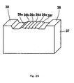
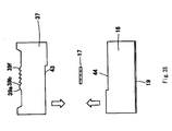
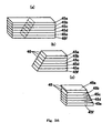
- a sixth manufacturing method for an optical multiplexer/demultiplexer is a manufacturing method for an optical multiplexer/demultiplexer that comprises an optical guiding means for guiding light by making the light be reflected between a light reflecting surface and plurality of wavelength selecting elements of which the transmission wavelengths are different from each other and for multiplexing/demultiplexing light having plurality of wavelengths, wherein the respective wavelength selecting elements are placed between a first substrate where the light reflecting surface is formed on the rear surface and a second substrate where plurality of prisms that become deflection elements are formed on the front surface, provided with: the step of layering plurality of plates and of processing the end surfaces of the layered plates so that the end surfaces become of plane form that incline relative to the direction in which the plates are layered; the step of realigning the above-described plates and thereby of forming an inverted pattern of the above-described plurality of prisms from an array of the inclining end surfaces; and the step of forming the above-described prisms on the front surface of the
- dies for fabricating prisms can be manufactured easily and with high precision.
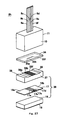
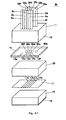
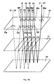
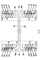
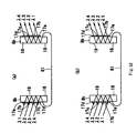
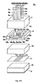
- FIG. 2 is a schematic exploded perspective diagram showing the structure of an optical multiplexer/demultiplexer 8a according to the first embodiment of the present invention.
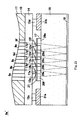
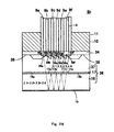
- FIG. 3 is a schematic cross sectional diagram along the plane that passes through cores 9 of optical fibers 9a to 9f of optical multiplexer/demultiplexer 8a shown in FIG. 2, and shows the state of demultiplexing or multiplexing.
- FIG. 4 is a schematic side diagram of optical multiplexer/demultiplexer 8a shown in FIG. 2. First, the configuration of optical multiplexer/demultiplexer 8a according to the present invention shown in FIG. 2 to FIG. 4 is described.
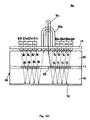
- Optical multiplexer/demultiplexer 8a is formed of an optical fiber array 11, a micro lens array 14, a transparent cover member 20, such as a glass plate, spacers 15a , 15b, 15c and 15d, a filter layer 17, an optical guiding block 16 and a mirror layer 19.
- optical fiber array 11 is gained by aligning optical fibers 9a, 9b, 9c, 9d, 9e and 9f in parallel with a constant pitch and without any intervals, and by attaching a connector 10 to the ends of the optical fibers.
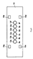
- Micro lens array 14 is provided with a number of (six in the drawings) micro lenses 12a, 12b, 12c, 12d, 12e and 12f on the lower surface thereof.
- Cover member 20 has an AR coating layer (antireflection film) 21 formed on the surface.
- Spacers 15a, 15b, 15c and 15d are members for maintaining the distance between micro lenses 12a to 12f and AR coating layer 21 constant.
- Filter layer 17 is made of peeling films 13, filters 17a, 17b, 17c and 17d, and dummy films 18a and 18b.
- Mirror layer 19 is a layer made of a dielectric multilayer film or a metal deposition film having high reflectance.
- Micro lens array 14, AR coating layer 21, filter layer 17 and mirror layer 19 are placed so as to be parallel to each other.
- micro lenses 12a to 12f are installed so as to be as proximate to AR coating layer 21 as possible.
- Optical fibers 9a to 9f within connector 10 are placed perpendicular to micro lens array 14.
- optical fibers 9a to 9f of optical fiber array 11 Any type of optical fiber, for example, ones where cores 9 are coated with clads of plastic or glass, ones where clads around cores 9 are coated with plastic layer, or ones where such said optical fibers are further coated with plastic layer or the like, may be used as optical fibers 9a to 9f of optical fiber array 11.
- FIG. 5 is a diagram showing the lower surface of micro lens array 14.
- the thickness of micro lens array 14 may be determined as follows, in order to satisfy this condition.
- the incident angle to the interface between the cores and the clads (incident angle that is measured relative to the normal line that is perpendicular to the interface) must be an angle that is no smaller than the total reflection angle.
- the incident angle to the interface between the cores and the clads is limited in such a manner, and therefore, the direction of emission of light from the ends of the cores and the degree to which light spreads are automatically determined.
- micro lens array 14 is designed so that light that has come out from the ends of the cores enters into micro lenses 12a to 12f when the cross section of light having the above-described constant spreading angle is enlarged to a size that is approximately the same as those of micro lenses 12a to 12f, or before the cross section of light having the above-described constant spreading angle is enlarged to a size that is approximately the same as those of micro lenses 12a to 12f, all of the light that is emitted from optical fibers 9a to 9f can be made to enter into micro lenses 12a to 12f.
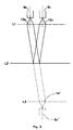
- FIG. 6 is a conceptual diagram showing the light path within optical multiplexer/demultiplexer 8a, where L1 indicates the main plane of micro lenses 12a to 12f, L2 indicates the surface of mirror layer 19 (hereinafter referred to as mirror surface L2), and L3 indicates a mirror image of lens main plane L1 relative to mirror surface L2. As shown in FIG.
- micro lens 12a it is desirable for micro lens 12a to be a lens in a form which allows light that has been emitted from optical fiber 9a to enter into lens main plane L1 (micro lens 12a), and after that, emit as parallel light of which the direction of the optical axis has been bent. It is desirable for the degree in bending of the direction of the optical axis of light, that is, the incident angle to mirror surface L2, to be the optimal angle, which is less than 10°, for the below described reasons.
- a lens for bending the direction of the optical axis of light (where the direction in which the light beam that passes through the center of the cross section of light flux progresses is referred to as the direction of the optical axis of light) after passing through the lens relative to the direction of the optical axis of light before entering into the lens is referred to as an inclination lens in the following.
- micro lens 12c it is desirable for micro lens 12c to have a form where the direction of the optical axis of light is bent so as to be efficiently coupled to optical fiber 9c when this light enters diagonally from below after the emission light of the above-described micro lens 12a is reflected from mirror surface L2.
- this optical multiplexer/demultiplexer 8a light enters into micro lenses 12c to 12f at the same incident angle, and light is emitted with the same angle of emergence, and therefore, micro lenses 12c to 12f may all be made to have the same form by using collimator lenses, or may be made to have forms that are different from each other so as to have optimal focal distances by using a condenser lens.
- micro lens 12b is not utilized and therefore, may be omitted.
- the micro lens array of the present embodiment shown in Fig.2 to Fig.5 have the micro lens 12b because of common use of the micro lens array with the second embodiment and the like.
- Micro lens 12b may be made to have the same form as micro lens 12c.
- Micro lenses 12a to 12f which satisfy the above requirements are gained by cutting out circular portions from aspherical lens 25 in positions outside of the optical axis of aspherical lens 25, as shown in the top diagram and frontal diagram of FIG. 7(a) and FIG. 7(b).
- micro lens array 14 having the above-described micro lenses 12a to 12f on the surface can be easily formed according to a stamper method or the like, where stampers which have inverted patterns of micro lenses 12a to 12f on the surfaces are pressed against a resin that has not yet been cured, such as an ultraviolet curing resin, which is then irradiated with ultraviolet rays, so that the resin is cured.
- a resin that has not yet been cured such as an ultraviolet curing resin, which is then irradiated with ultraviolet rays, so that the resin is cured.
- micro lenses 12a to 12f and spacers 15a, 15b, 15c and 15d can be formed at the same time.
- micro lenses 12a to 12f and spacers 15a to 15d can be formed at the same time, the manufacturing process can be simplified, in comparison with the case where spacers 15a to 15d which have been individually prepared are made to adhere to micro lens array 14, and the positional precision between micro lenses 12a to 12f and filters 17a to 17d can be increased.
- optical multiplexer/demultiplexer 8a the respective components are formed and placed so that a parallel light flux which has been emitted from optical fiber 9a, transmitted through micro lens 12a (the region of main plane L1 that is below optical fiber 9a) and has been reflected from mirror surface L2 enters into micro lens 12c (the region of main plane L1 that is below optical fiber 9c), as shown in FIG. 6.
- the position of mirror surface L2 is set so that parallel light that has been emitted from micro lens 12a enters entirely into mirror image L3 (mirror image 12c' of micro lens 12c) of lens main surface L1 relative to mirror surface L2 so as to be collected and coupled to mirror image 9c' of optical fiber 9c relative to mirror surface L2, as shown in FIG. 6.
- Adjustment of the interval between micro lens array 14 and mirror layer 19 can be carried out by adjusting the thickness of optical guiding block 16 and the thickness of cover member 20.
- micro lens 12a may be designed so that the angle of bending of micro lens 12a becomes an appropriate angle.
- an adhesive that has not yet been cured is applied between optical fiber array 11 and micro lens array 14, and after that, respective optical fibers 9a, 9b, 9c, 9d, 9e and 9f are irradiated with light in the condition where the adhesive has not yet been cured, and the mutual positions thereof are adjusted while the intensity of light that has transmitted through respective micro lenses 12a, 12b, 12c, 12d, 12e and 12f is being measured, and then, the adhesive may be cured when the optimal positions are gained.
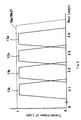
- FIG. 8 is a graph showing the characteristics of the transmission wavelengths of filters 17a to 17d, dummy films 18a and 18b, and AR coating layer 21, where the lateral axis indicates the wavelength and the longitudinal axis indicates transmittance of light.
- Filters 17a, 17b, 17c and 17d are dielectric multilayer films which, as shown by the solid lines in FIG. 8, transmit light having wavelength bands of which the centers are wavelengths ⁇ 1, ⁇ 2, ⁇ 3 and ⁇ 4, respectively, and reflect light having wavelength bands other than these.
- dummy films (spacers) 18a, 18b and AR coating layer 21 are, for example, members using thin film glass, quartz, transparent resin films or the like, and as shown by the broken line in FIG. 8, transmit light having all wavelength bands.
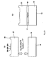
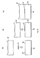
- a manufacturing method for filter layer 17 of optical multiplexer/demultiplexer 8a is described in reference to FIG. 9 and FIG. 10.
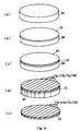
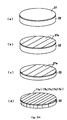
- a peeling film 13 which is made of a transparent substance and is very thin is grown, as shown in FIG. 9 (b), by using a spin coater on the surface of a substrate 22, such as glass, shown in FIG. 9(a).
- the substance of this peeling film 30 may be a substance such as polyimide, which is transparent and easily peels from substrate 22 when placed under certain conditions, for example, when heat is applied, when contacted with water or when irradiated with ultraviolet rays, after the formation of a thin film.
- a filter thin film (dielectric multilayer film) 27 having particular characteristics for each substrate 22 is formed on the surface of peeling film 13, as shown in FIG. 9(c).
- Such substrates 22 on which peeling films 13 and filter thin films 27 are formed are prepared so that the number of types is the same as that of the types of required filters 17a to 17d.
- dummy films 18a and 18b are formed of transparent thin glass plates, crystal, transparent resin films or the like, so as to have the same thickness as the total thickness of peeling film 13 and filter thin film 27.
- filter thin film 27 and peeling film 13 on substrate 22 are cut in width into filters 17a, 17b, 17c and 17d which are utilized in optical multiplexer/demultiplexer 8a.
- peeling film 13 is peeled from substrate 22, as shown in FIG. 9(e), by applying heat, making it make contact with water, irradiating it with ultraviolet rays or the like.
- a transparent adhesive is applied to the surface of the parent substrate of optical guiding block 16, and filters 17a, 17b, 17c and 17d, as well as dummy films 18a and 18b, where peeling films 13 provided on the rear surfaces are positioned one by one in the order shown in FIG. 10(f) and made to adhere to the front surface of the parent surface of optical guiding block 16.
- filter layer 17 may be made to adhere to the parent substrate of optical guiding block 16 by pressing the top surface with a flat plate.
- filter layer 17 and optical guiding block 16 may be made to adhere to each other by pressing the parent substrate of optical guiding block 16, to the front surface of which a transparent adhesive has been applied, against the rear surfaces of filters 17a to 17d and dummy films 18a and 18b, which have been aligned on a flat support.
- mirror layer 19 may be formed by pasting a sheet where a metal thin film has been formed, or by depositing a metal material on the rear surface of the parent substrate of optical guiding block 16.
- filters 17a to 17b and dummy films 18a and 18b may be made to adhere to the front surface of the parent substrate of optical guiding block 16 after mirror layer 19 has been formed in advance on the rear surface.
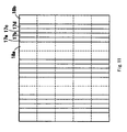
- optical guiding block 16 where filter layer 17 and mirror layer 19 have been formed on the front surface and on the rear surface is cut into the individual forms of optical guiding blocks 16, as shown in FIG. 10(g) by cutting it along the broken lines of FIG. 11, and thus, optical guiding blocks 16 where filter layers 17 and mirror layers 19 have been formed can be efficiently mass produced.
- cover member 20, on which AR coating layer 21 has been formed is joined to filter layer 17 on the front surface of optical guiding block 16.
- filter layer 17 on the parent substrate and the parent substrate of cover member 20 on the front surface of which AR coating layer 21 has been formed may be made to adhere to each other with a transparent adhesive, and after that, cutting may be carried out as shown in FIG. 11, so that optical multiplexers/demultiplexers 8a can be manufactured more efficiently.
- filter layer 17 in the case where filter layer 17 is covered with cover member 20 before cutting in this manner, filter layer 17 can be prevented frombecoming stained or damaged at the time of cutting, and thus, the yield can be lowered.
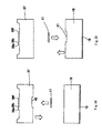
- filter layer 17 may be manufactured in accordance with the following method that is described in reference to FIG. 12 and FIG. 13.
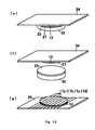
- a peeling film 23 is formed, as shown in FIG. 12(b), by using a spin coater on the surface of substrate 22 shown in FIG. 12(a).
- This peeling film 23 may be made of a substance of which the properties change as a result of application of heat, contact with water, irradiation with ultraviolet rays or the like, such as polyimide, so as to easily peel from substrate 22 or filter thin film 27.
- a filter thin film 27 made of a dielectric multilayer film having particular properties for each substrate 22 is grown on the surface of peeling film 23, as shown in FIG. 12(c).
- Such substrates 22 on which filter thin films 27 have been grown are prepared, of which the number of types is the same as that of required filters.
- Peeling film 13 is further grown on the surface of filter thin film 27, as shown in FIG. 12(d).
- a dicing tape 24 is made to adhere to the surface of upper peeling film 13, and peeling film 23 on the substrate 22 side is peeled from filter thin film 27 by means of application of heat, irradiation with ultraviolet rays or the like, as shown in FIG. 13 (f).
- only substrate 22 may be peeled while lower peeling film 23 stays adhered to filter thin film 27.
- filter thin film 27 is covered with peeling films 13 and 23 on both sides, and therefore, filter thin film 27 is prevented from being damaged, and becomes easy to handle.
- dicing tape 24 on which filter thin film 27 has been formed is turned upward and cut in width into filters 17a, 17b, 17c and 17d, as shown in FIG. 13(g).
- dicing tape 24 is peeled frompeeling film 13 by irradiating it with ultraviolet rays or the like, and then, respective filters 17a to 17d are aligned on optical guiding block 16, and peeling film 13 is made to adhere to optical guiding block 16 with a transparent adhesive.
- dummy films 18a and 18b which have been grown so as to have a thickness that is the same as the total thickness of peeling film 13 and filter thin film 27, are also made to adhere to the surface of optical guiding block 16 with a transparent adhesive. After this, cutting may be carried out, so as to form individual filter layers 17, in the same manner as in the above-described manufacturing process.
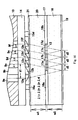
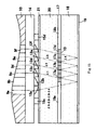
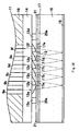
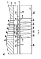
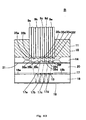
- FIG. 14 is an enlarged cross sectional diagram of a portion of FIG. 3, and illustrates the manner of demultiplexing in optical multiplexer/demultiplexer 8a according to the present invention.
- Light that has transmitted through dummy film 18a further transmits optical guiding block 16 so as to be reflected from the surface of mirror layer 19, and then again transmits through optical guiding block 16 so as to reach filter layer 17.
- Filter 17a is placed in this portion of filter layer 17, and therefore, light having wavelength ⁇ 1 transmits through filter 17a so as to enter into micro lens 12c, where the direction of the optical axis is bent, and is coupled to optical fiber 9c. Accordingly, only light having wavelength ⁇ 1 is taken out from the light emitting end of optical fiber 9c.
- light multiplexer/demultiplexer 8a can demultiplex light that has been multiplexed. Contrarily, in the case where light having wavelengths ⁇ 1 to ⁇ 4 that has propagated through optical fibers 9c to 9f is multiplexed and taken out from optical fiber 9a, optical multiplexer/demultiplexer 8a can be utilized as a multiplexer.
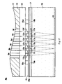
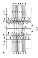
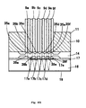
- FIG. 15 illustrates the multiplexing operation of optical multiplexer/demultiplexer 8a according to the present invention.
- Light having wavelengths ⁇ 1, ⁇ 2, ⁇ 3 and ⁇ 4 propagates through optical fibers 9c, 9d, 9e and 9f, respectively, and is emitted from the end surfaces of optical fibers 9c, 9d, 9e and 9f.
- light having wavelength ⁇ 4 that has been emitted from optical fiber 9f is converted to parallel light after having transmitted through micro lens 12f, where the direction of the optical axis is bent, and transmits through cover member 20, filter 17d and optical guiding block 16 so as to be reflected frommirror layer 19.
- Light having wavelength ⁇ 4 that has been reflected from mirror layer 19 enters into filter 17c and is reflected from filter 17c.
- light having wavelength ⁇ 3 that has been emitted from optical fiber 9e is converted into parallel light after having transmitted through micro lens 12e, where the direction of the optical axis is bent, and transmits through cover member 20 and filter 17c.
- light having wavelength ⁇ 4 that has been reflected from filter 17c and light having wavelength ⁇ 3 that has transmitted through filter 17c propagate in the same direction within optical guiding block 16, and are reflected from mirror layer 19.
- Light having wavelengths ⁇ 3 and ⁇ 4 that has been reflected from mirror layer 19 enters into filter 17b and is reflected from filter 17b.
- light having wavelength ⁇ 2 that has been emitted from optical fiber 9d is converted into parallel light after having transmitted through micro lens 12d, where the direction of the optical axis is bent, and transmits through cover member 20 and filter 17b.
- light having wavelengths ⁇ 3 and ⁇ 4 that has been reflected from filter 17b and light having wavelength ⁇ 2 that has transmitted through filter 17b propagate in the same direction within optical guiding block 16 so as to be reflected from mirror layer 19.
- Light having wavelengths ⁇ 2, ⁇ 3 and ⁇ 4 that has been reflected from mirror layer 19 enters into filter 17a and is reflected from filter 17a.
- light having wavelength ⁇ 1 that has been emitted from optical fiber 9c is converted into parallel light after having transmitted through micro lens 12c, where the direction of the optical axis is bent, and transmits through cover member 20 and filter 17a.
- light having wavelengths ⁇ 2, ⁇ 3 and ⁇ 4 that has been reflected from filter 17a and light having wavelength ⁇ 1 that has transmitted through filter 17a propagate in the same direction within optical guiding block 16 so as to be reflected from mirror layer 19.
- Light having wavelengths ⁇ 1, ⁇ 2, ⁇ 3 and ⁇ 4 that has been reflected from mirror layer 19 transmits through optical guiding block 16, dummy film 18a and cover member 20 so as to enter into micro lens 12a.
- optical multiplexer/demultiplexer 8a can multiplex light having respective wavelengths.
- thickness w2 of optical guiding block 16 may be adjusted so that the intervals between adjacent micro lenses 12c, 12d, 12e and 12f coincide with intervals d2 of light that is reflected from mirror layer 19 in the lens portions, in accordance with the deflection angles of light of which the direction of the optical axis has been bent.
- interval d1 between micro lens 12a and micro lens 12c can be adjusted by thickness w1 of cover member 20.
- the thickness of cover member 20 is thick enough to be adjustable so as to design with precision the light path in optical multiplexer/demultiplexer 8a according to the present invention, and therefore, optical multiplexer/demultiplexer 8a where loss of light is small can be provided.
- micro lens array 14 is designed so that interval d1 between micro lens 12a and micro lens 12c becomes two times greater than interval d2 of the portions where light is reflected from mirror layer 19 when thickness w2 of optical guiding block 16 and thickness w1 of cover member 20 are the same, the respective intervals between optical fibers 9a, 9b, 9c, 9d, 9e and 9f of optical fiber array 1 become equal intervals, and optical guiding block 16 and cover member 20 can be formed of the same material, and thus, the cost for procurement of materials and processing can be reduced.
- micro lens 12a may be designed so that the incident angle of light that has transmitted through micro lens 12a to mirror layer 19 becomes an appropriate angle that is no greater than 10°, and the reason for this is as follows.
- the incident angle to mirror layer 19 becomes the incident angle to filter layer 17 without change, where when this angle becomes too great, a difference in the transmittance (wavelength dependent loss) due to the difference in the incident angle of P deflection and S deflection becomes greater, and properties of light having wavelength ⁇ 1 that has transmitted through filter 17a and light having wavelength ⁇ 1 before transmitting through filter 17a become different from each other. That is, reproducibility of light becomes poor.
- the incident angle to mirror layer 19 must not be too large, in the case where the incident angle to mirror layer 19 is too small, light fails to enter into micro lens 12c, optical multiplexer/demultiplexer 8a becomes large in size and attenuation of light becomes great, unless the thicknesses of optical guiding block 16 and cover member 20 are increased so as to increase the length of the light path.
- Optical multiplexer/demultiplexer 8a may be contained in a casing 32, as shown in the schematic cross sectional diagram of FIG. 16, where the inlet is sealed with an adhesive 33 when being utilized.
- Optical multiplexer/demultiplexer 8a is provided with micro lens array 14, in a manner where the direction of the optical axis of light can be bent by micro lenses 12a to 12f. Accordingly, the light emitting end surface of optical fiber array 11, where optical fiber 9a for propagating multiplexed light and optical fibers 9c to 9f for propagating light of each wavelength after demultiplexing are aligned in parallel and filter layer 17 or mirror layer 19 can be placed so as to be parallel to each other, and thus, a compact optical multiplexer/demultiplexer 8a can be provided even in the case where the number of wavelengths to be demultiplexed is increased.
- optical multiplexer/demultiplexer 8a can be designed so that demultiplexed light enters with precision into micro lenses 12c to 12f, by adjusting the thicknesses of cover member 20 and optical guiding block 16.
- FIG. 17 is a schematic cross sectional diagram of a portion of an optical multiplexer/demultiplexer 8b according to the second embodiment of the present invention, and is a diagram that corresponds to FIG. 14 which is described in the first embodiment.
- Filters 17a, 17b, 17c, 17d and 17e are dielectric multilayer films for respectively transmitting light having wavelengths ⁇ 1, ⁇ 2, ⁇ 3, ⁇ 4 and ⁇ 5.
- Filter layer 17 is formed of a region made of filters 17a to 17e and peeling films 13, and of dummy films (spacers) 18a and 18b.
- Filter layer 17 can be manufactured in accordance with the manufacturing process that is described in the first embodiment. Descriptions of the components of optical multiplexer/demultiplexer 8b shown in FIG. 17 which have the same configuration as those described in the first embodiment are omitted.
- the surface of filter layer 17 is covered with a film 20a which is transparent and very thin glass or the like, so as to protect filters 17a to 17e from humidity or the like.
- An AR coating layer 21 is formed on the surface of film 20a.
- Respective filters 17a to 17e must be placed on the light path of light that has been reflected from mirror layer 19 when this light enters into corresponding micro lenses 12b to 12f, and therefore, it is necessary to design the arrangement of respective filters 17a to 17e using the thickness of optical guiding block 16 and the incident angle of light to mirror layer 19 in the case where the thickness of cover member 20 on filter layer 17 is great, as shown in the first embodiment.
- filters 17a to 17e and micro lenses 12b to 12e can be put in proximity to each other, in comparison with those of optical multiplexer/demultiplexer 8a of the first embodiment. Accordingly, even in a case where filters 17a to 17e are placed in the same positions as micro lenses 12b to 12f in such a manner that dummy film 18a is formed in a position that faces micro lens 12a, and filters 17a, 17b, 17c, 17d and 17e are formed in positions that face micro lenses 12b, 12c, 12d, 12e and 12f, light that has been reflected from mirror layer 19 can be made to enter into respective filters 17a to 17e. As described above, according to the present embodiment, the design of the arrangement of filter layer 17 is not complicated, unlike that of optical multiplexer/demultiplexer 8a shown in the first embodiment.
- the surfaces of filters 17a to 17e may not necessarily be covered with film 20a or AR coating layer 21.
- the total thickness of film 20a and AR coating layer 21 must be equal to the total thickness of peeling film 13 and filters 17a to 17e.
- FIG. 19 is a schematic cross sectional diagram of a portion of an optical multiplexer/demultiplexer 8c according to the third embodiment of the present invention, and is a diagram that corresponds to FIG. 14 which is described in the first embodiment.
- the descriptions of the components of optical multiplexer/demultiplexer 8c shown in FIG. 19 which have the same configuration as those described in the first embodiment are omitted.
- Filter layer 17 is formed of filters 17a to 17e, peeling films 13 and dummy film 18a. Filter layer 17 can be manufactured in accordance with the manufacturing method that is described in the first embodiment.
- Filters 17a, 17b, 17c, 17d and 17e are dielectric multilayer films for respectively transmitting light having wavelengths ⁇ 1, ⁇ 2, ⁇ 3, ⁇ 4 and ⁇ 5. So that the height of micro lens array 14 can be adjusted, spacer blocks 31a and 31b are sandwiched between optical guiding block 16 and micro lens array 14.
- optical multiplexer/demultiplexer 8c a transparent adhesive is applied to a transparent plate 28, such as a glass plate, and filter layer 17 is formed on top of this.
- a film 20a on the surface of which an AR coating layer 21 is provided is further made to adhere to the top of filter layer 17 with a transparent adhesive.
- transparent plate 28 on the surface of which filter layer 17 or the like is formed, and spacer blocks 31a and 31b are made to adhere to the surface of optical guiding block 16, and furthermore, micro lens array 14 or the like is made to adhere to the top thereof, and thus, optical multiplexer/demultiplexer 8c is completed.
- FIG. 20 is a schematic cross sectional diagram of a portion of an optical multiplexer/demultiplexer 8d according to the fourth embodiment of the present invention, and is a diagram that corresponds to FIG. 14 which is described in the first embodiment.
- Filter layer 17 of optical multiplexer/demultiplexer 8d according to the present embodiment is formed of filter blocks 29a, 29b, 29c, 29d, 29e, 29f and 29g, where filters 17a, 17b, 17c, 17d and 17e, as well as an AR coating layer 21, are formed on the surfaces of transparent blocks, such as glass.
- Filters 17a, 17b, 17c, 17d and 17e are dielectric multilayer films for respectively transmitting light having wavelength bands of ⁇ 1, ⁇ 2, ⁇ 3, ⁇ 4 and ⁇ 5, and for reflecting light having other wavelength bands.
- a manufacturing method for filter layer 17 according to the present embodiment is described in reference to FIG. 21 (a) to FIG. 21 (e).
- a filter thin film 27 having particular filter characteristics is formed on the surface of a transparent substrate 22, such as glass.
- Substrates 22 on the surface of which filter thin films 27 are formed are prepared, where the number of types of substrates 22 is the same as the number of types of filters 17a, 17b, 17c, 17d and 17e.
- substrates 22 on the surfaces of which AR coating layers 21 having the same thickness as filter thin films 27 are formed are also prepared.
- the rear surface of substrate 22 is polished, so as to reduce the thickness of substrate 22 as much as possible, and is cut in width into filters 17a, 17b, 17c, 17d and 17e or AR coating layers 21, which are utilized in optical multiplexer/demultiplexer 8d, as shown in FIG. 21(c).
- Substrate 22 that has been cut into stripe forms on the surfaces of which filters 17a to 17e or AR coating layers 21 are formed become filter blocks 29a to 29g.
- filter blocks 29a to 29e with filters 17a to 17e and filter blocks 29f and 29g with AR coatings 21 are aligned in order shown in FIG. 21(d), and the sides are made to adhere to each other, and the rear surface thereof is polished so as to be flat, and thus, filter layer 17, as shown in FIG. 21(e), is completed.
- This filter layer 17 is made to adhere to the upper surface of optical guiding block 16 with a transparent adhesive.
- FIG. 22 is a schematic cross sectional diagram of a portion of an optical multiplexer/demultiplexer 8e according to the fifth embodiment of the present invention, and is a diagram that corresponds to FIG. 14 of the first embodiment and FIG. 20 which is described in the fourth embodiment.
- the descriptions of the components of this optical multiplexer/demultiplexer 8e which have the same configuration as those described in the first or fourth embodiment are omitted.
- Filters 17a, 17b, 17c , 17d and 17e are dielectric multilayer films for respectively transmitting light having wavelengths ⁇ 1, ⁇ 2, ⁇ 3, ⁇ 4 and ⁇ 5, and for reflecting light having other wavelength bands.
- Filter layer 17 is formed of filter blocks 29a to 29f where these filters 17a to 17e, as well as AR coating layers 21, are formed on the surfaces of transparent blocks, such as glass.
- filter layer 17 (filter blocks 29a to 29f) of optical multiplexer/demultiplexer 8e according to the present embodiment is placed only below micro lenses 12a to 12f. Only spacer blocks 31a and 31b which are completely separated from micro lens array 14, as shown in FIG. 22, may be used as the spacers for determining the interval between micro lenses 12a to 12f and filter layer 17. However, in the case where, as in optical multiplexer/demultiplexer 8e' shown in FIG.
- spacers 15a, 15b, 15c and 15d which are formed so as to be integrated with micro lens array 14, and spacer blocks 31a and 31b for adjusting the height by being added to these spacers 15a to 15b may be used, micro lens array 14 that is described in the first embodiment can also be utilized in this embodiment.
- spacers 15a and 15c are joined to spacer block 31a, and spacers 15b and 15d are joined to spacer block 31b.
- Filter layer 17 of the present embodiment can be manufactured in accordance with the manufacturing method for filter layer 17 that is described in reference to FIG. 21(a) in the fourth embodiment.
- tensile stress occurs in filter thin film 27 that is formed on the upper surface of substrate 22 shown in FIG. 21 in the direction toward its center, and therefore, the glass substrate may be warped or cracked due to this tensile stress when the rear surface of substrate 22 is polished.
- filter thin film 27 is cut with a dicing blade, as shown in FIG. 24(b), after the formation of filter thin film 27 on the surface of substrate 22, and after that, as shown in FIG. 24(c), the rear surface of substrate 22 may be polished to a desired thickness.
- filter thin film 27a may not necessarily be cut into widths of filters 17a to 17e, but rather, may be cut so as to have widths that are several times greater than the widths of filters, and which sufficiently relieve the above-described stress.
- filter thin film 27a and substrate 22 are completely cut into widths of filters 17a to 17e which are utilized in optical multiplexer/demultiplexer 8e.
- the process after this is the same as that described in the fourth embodiment.
- FIG. 25 is a schematic cross sectional diagram of a portion of an optical multiplexer/demultiplexer 8f according to the sixth embodiment of the present invention, and is a diagram that corresponds to FIG. 14 which is described in the first embodiment.
- This optical multiplexer/demultiplexer 8f is formed of an optical fiber array 11, a micro lens array 14 on the lower surface of which micro lenses 12a to 12f and spacers 15a, 15b, 15c and 15d are provided, filter layer 17 and mirror layer 19.
- Filter layer 17 is formed of filter blocks 29a, 29b, 29c, 29d, 29e, 29f and 29g, where filters 17a, 17b, 17c, 17d and 17e, and AR coating layer 21, as well as dummy film 18b, are formed on the surfaces of transparent blocks, such as glass.
- Filters 17a, 17b, 17c, 17d and 17e are dielectric multilayer films for respectively transmitting light having wavelengths ⁇ 1, ⁇ 2, ⁇ 3, ⁇ 4 and ⁇ 5, and for reflecting light having other wavelength bands.
- filter layer 17 is manufactured in accordance with the manufacturing method that is described in the fourth and fifth embodiments (FIG. 21 and FIG. 24), and mirror layer 19 is formed on the rear surface of this filter layer 17.
- FIG. 26 is a schematic cross sectional diagram of an optical multiplexer/demultiplexer 8g according to the seventh embodiment of the present invention, and illustrates the structure thereof and the manner in which an optical signal is demultiplexed.
- This optical multiplexer/demultiplexer 8g has a form where two optical multiplexers/demultiplexers, each of which is described in the first embodiment, are placed and integrated symmetrically with mirror layer 19 placed in between.
- Optical multiplexer/demultiplexer 8g is formed of an optical fiber array 11a, a micro lens array 14a, a filter layer 17L, an optical guiding block 16a, a mirror layer 19, an optical guiding block 16b, a filter layer 17M, a micro lens array 14b and an optical fiber array 11b.
- optical fiber array 11a is made of optical fibers 9a, 9b, 9c, 9d, 9e and 9f and connector 10.
- micro lens array 14a is provided with micro lenses 12a, 12b, 12c, 12d, 12e and 12f and spacers 15a, 15b, 15c and 15d on the lower surface.
- Micro lens array 14b is provided with micro lenses 12g, 12h, 12i, 12j, 12k and 121 and spacers 15a, 15b, 15c and 15d on the lower surface.
- Optical fiber array 11b is made of optical fibers 9g, 9h, 9i, 9j, 9k and 9l and connector 10.
- Filter layer 17L is formed of an AR coating layer (antireflection film) 21, filters 17a, 17b, 17c, 27d and 17e for respectively transmitting light having wavelengths ⁇ 1, ⁇ 2, ⁇ 3, ⁇ 4 and ⁇ 5, peeling films 13 and dummy film (spacer) 18b.
- AR coating layer 21 faces micro lens 12a
- filters 17a to 17e face micro lenses 12b to 12f, respectively.
- filter layer 17M is formed of filters 17f, 17g, 17h, 17i and 17j for respective light having wavelengths ⁇ 6, ⁇ 7, ⁇ 8, ⁇ 9 and ⁇ 10 and dummy films (spacers) 18a and 18b.
- dummy film 18a faces micro lens 12g, and filters 17f to 17j face micro lenses 12h to 121, respectively.
- Mirror layer 19 is formed of a substance layer having a high reflectance, such as a metal film, and both surfaces thereof are reflective surfaces.
- a filter 17k for transmitting light having wavelengths ⁇ 6, ⁇ 7, ⁇ 8, ⁇ 9 and ⁇ 10 is provided in an opening that is provided in a portion of mirror layer 19.
- Light having wavelengths ⁇ 1 to ⁇ 5 is reflected from this filter 17k.
- the reflected light that is light having wavelengths ⁇ 1 to ⁇ 5 is repeatedly reflected between filter layer 17L and mirror layer 19, while light having wavelengths ⁇ 1, ⁇ 2, ⁇ 3, ⁇ 4 and ⁇ 5 sequentially transmits through respective filters 17a, 17b, 17c, 17d and 17e, so as to be demultiplexed, and thus, light having wavelengths ⁇ 1, ⁇ 2, ⁇ 3, ⁇ 4 and ⁇ 5 can respectively be taken out from optical fibers 9b, 9c, 9d, 9e and 9f.
- light having wavelengths ⁇ 6 to ⁇ 10 that has transmitted through filter 17k of mirror layer 19 transmits through optical guiding block 16b, so as to enter into filter layer 17M.
- light having wavelengths ⁇ 6 to ⁇ 10 is repeatedly reflected between filter layer 17M and mirror layer 19, while light having wavelengths ⁇ 6, ⁇ 7, ⁇ 8, ⁇ 9 and ⁇ 10 sequentially transmits through respective filters 17f, 17g, 17h, 17i and 17j, so as to be demultiplexed, and thus, light having wavelengths ⁇ 6, ⁇ 7, ⁇ 8, ⁇ 9 and ⁇ 10 can respectively be taken out from optical fibers 9h, 9i, 9j, 9k and 91.
- Mirror layer 19 is shared in optical multiplexer/demultiplexer 8g according to the present invention, which can thus be made compact and demultiplex light into many wavelengths.
- optical fibers 9g and 12g are not needed, they are provided in this embodiment, taking into consideration a case where they are used in other embodiments.
- lenses made of portions of an aspherical lens which can bend the direction of the optical axis of light that enters into and is emitted from optical fibers 9a to 9f are used as micro lenses 12a to 12f of micro lens array 14, such lenses have forms which are not rotationally symmetric around the axes, and are categorized as special lenses of which the processing or formation is difficult, and thus, cost is easily increased.
- the eighth embodiment is provided taking this problem into consideration, and the direction of the optical axis of light is bent by using a prism.
- FIG. 27 is an exploded perspective diagram of an optical multiplexer/demultiplexer 8h according to the eighth embodiment of the present invention
- FIG. 28 is a schematic cross sectional diagram thereof.
- this optical multiplexer/demultiplexer 8h end portions of a number of optical fibers 9a, 9b, 9c, 9d, 9e and 9f, which are put together in a line, are inserted into connector 10, and thereby, the end portions of respective optical fibers 9a to 9f are supported in parallel by connector 10 made of plastic.
- the end surfaces of respective optical fibers 9a to 9f are aligned and exposed from the lower surface of optical fiber array 11.
- Micro lens array 34 in panel form is made to adhere to the lower surface of this connector 10.
- micro lenses 35a, 35b, 35c, 35d, 35e and 35f are formed on the surface of micro lens array 34 so as to be aligned.
- These micro lenses 35a to 35f are lenses (hereinafter referred to as rectilinear lenses) where the direction of the optical axis of light (direction in which the light beam that passes through the center of the cross section of light flux progresses) after transmitting through the lens coincides with the direction of the optical axis of light before entering into the lens.
- Such rectilinear lenses are general lenses for emitting a light beam that has entered along the optical axis of the lens in a manner where the light beam passes along the optical axis of the lens, and include spherical lenses having a form that is rotationally symmetric around the optical axis, aspherical lenses and anamorphic lenses of which the design and manufacture are easy and cost is low in comparison with inclination lenses.
- the alignment pitch of micro lenses 35a to 35f is equal to the alignment pitch of optical fibers 9a to 9f, and thus, micro lenses 35a to 35f are placed so that the optical axes thereof coincide with those of optical fibers 9a to 9f, respectively.
- the thickness of micro lens array 34 is set so that the end surfaces of respective optical fibers 9a to 9f are located approximately at focal points of respective micro lenses 35a to 35f.
- a block for multiplexing/demultiplexing 36 made of a prism block 37, a filter layer 17 and an optical guiding block 16 is placed directly beneath micro lens array 34 that is attached to optical fiber array 11.
- Prism block 37 is a block in approximately parallelepiped formmade of glass or a transparent plastic material, and as shown in FIG. 29, spacers 38 protrude from the two end portions on the upper surface of the block, and a number of prisms 39a, 39b, 39c, 39d, 39e and 39f of which the cross sections are in triangular form are provided so as to have a pitch that is equal to that of micro lenses 35a to 35f between the two spacers 38.
- the respective prisms 39a to 39f have an equal inclination angle, and prisms 39b to 39f from among these are inclined in the same direction, while only prism 39a inclines in the direction opposite that of the other prisms 39b to 39f.
- spacers 38 and prisms 39a to 39f extend in the direction from the front to the rear while maintaining the same cross sectional forms on the upper surface of prism block 37.
- spacers 38 are provided so as to protrude from the two end portions on the upper surface of prism block 37 shown in FIG. 29, a spacer 38 may be formed along the four sides on the upper surface of prism block 37, so that the number of prisms 39a to 39f is provided within a recess in the region surrounded by spacer 38, as shown in FIG. 42.
- Filter layer 17 is formed between a pair of dummy films 18a and 18b by aligning a number of filters 17a, 17b, 17c and 17d of which the transmission wavelength regions are ⁇ 1, ⁇ 2, ⁇ 3 and ⁇ 4 (see FIG. 8).
- Filters 17a to 17d are formed so as to have a width that is equal to the pitch of micro lenses 35a to 35f, and the thickness of dummy films 18a and 18b is made to be equal to the thickness of filters 17a to 17d, in order to make uniform the thickness of filter layer 17.
- filters 17a to 17d, as well as dummy films 18a and 18b may be made to adhere in advance to a thin transparent resin film (not shown) so as to be integrated.
- a peeling layer made of a polyimide film or the like may exist beneath respective filters 17a to 17d, and an AR coating layer may be formed on the surface of prism block 37.
- Light guiding block 16 is formed in parallelepiped form of glass, quartz or a transparent plastic material, and a mirror layer 19 made of a dielectricmultilayer film, a metal deposition film or the like having high reflectance is formed on the lower surface of the optical guiding block.
- Block for multiplexing/demultiplexing 36 is formed, as shown in FIG. 30, by sandwiching this filter layer 17 between the lower surface of prism block 37 and the upper surface of optical guiding block 16 so as to join and integrate prism block 37 and optical guiding block 16.
- dummy films 18a and 18b having the same thickness as filters 17a to 17d, and therefore, the surface of filter layer 17 becomes flat, and it becomes easy to join prism block 37.
- Block for multiplexing/demultiplexing 36 is placed in proximity of and below micro lens array 14, and prisms 39a to 39f are made to face micro lenses 35a to 35f, respectively. As a result of this, micro lenses 35a to 35f, filter layer 17 and mirror layer 19 are placed so as to be parallel to each other.
- optical multiplexer/demultiplexer 8h that has been assembled in this manner, light that has been emitted from optical fiber 9a is converted to parallel light by micro lens 35a and refracted by prism 39a so as to enter prism block 37, and then, is directed to mirror layer 19. Contrarily, parallel light that is directed to prism 39a after being reflected from mirror layer 19 is refractedbyprism39a so as to proceed parallel to the optical axis of optical fiber 9a, and is condensed by micro lens 35a so as to be coupled to optical fiber 9a.
- dummy film 18a is located on the light path of this light.
- optical fiber 9c light that has been emitted from optical fiber 9c is converted to parallel light by micro lens 35c and refracted by prism 39c so as to enter into prism block 37, and then, is directed to mirror layer 19.
- parallel light that is directed to prism 39c after being reflected from mirror layer 19 is refractedbyprism39c so as to proceed parallel to the optical axis of optical fiber 9c, and then, is condensed by micro lens 35c so as to be coupled to optical fiber 9c.
- filter 17a is located on the light path of this light.
- optical fibers 9d to 9f In the same manner, light that has been emitted from optical fibers 9d to 9f is converted to parallel light by micro lenses 35d to 35f, respectively, and refracted by prisms 39d to 39f so as to enter into prism block 37, and then, is directed to mirror layer 19. Contrarily, parallel light that is directed to prisms 39d to 39f after being reflected from mirror layer 19 is refracted by prisms 39d to 39f, respectively, so as to proceed parallel to the optical axis of optical fibers 9d to 9f, and then, is condensed by micro lenses 35d to 35f so as to be coupled to optical fibers 9d to 9f.
- filters 17b, 17c and 17d are located on the light path or this light, respectively.
- the intervals between the positions where light that has transmitted through respective filters 17a to 17d returns to the plane on which the prisms are formed can be adjusted by adjusting the thickness of optical guiding block 16.
- the horizontal distance between the position where light transmits through prism 39a and the position where light that has been reflected from mirror layer 19 and transmitted through filter 17a returns to the plane on which the prisms are formed can be adjusted by adjusting the thickness of prism block 37. Accordingly, the thickness of prism block 37 and the thickness of optical guiding block 16 can be adjusted, and thereby, the positions where light returns to prisms 39c to 39f can be adjusted so as to coincide with the positions of prisms 39c to 39f.
- light having wavelengths ⁇ 2, ⁇ 3 and ⁇ 4 that has been reflected from filter 17a is again reflected frommirror layer 19 so as to enter into filter 17b.
- Light having wavelength ⁇ 2 from among light that has entered into filter 17b transmits through filter 17b so as to enter into prism 39d, and the direction of the optical axis is bent at the time when the light transmits through prism 39d, and the light is coupled to optical fiber 9d by means of micro lens 35d. Accordingly, it is possible to take out only light having wavelength ⁇ 2 from the light emitting end of optical fiber 9d.
- light having wavelengths ⁇ 3 and ⁇ 4 that has been reflected from filter 17b is further reflected from mirror layer 19 so as to enter into filter 17c.
- Light having wavelength ⁇ 3 from among the light that has entered into filter 17c transmits through filter 17c so as to enter into prism 39e, and the direction of the optical axis is bent at the time when the light transmits through prism 39e, and the light is coupled to optical fiber 9e by means of micro lens 35e. Accordingly, it is possible to take out only light having wavelength ⁇ 3 from the light emitting end of optical fiber 9e.
- light having wavelength ⁇ 4 that has been reflected from filter 17c is further reflected from mirror layer 19 so as to enter into filter 17d.
- Light having wavelength ⁇ 4 that has transmitted through filter 17d enters into prism 39f, and the direction of the optical axis is bent at the time when the light transmits through prism 39f, and the light is coupled to optical fiber 9f by means of micro lens 35f. Accordingly, it is possible to take out light having wavelength ⁇ 4 from the light emitting end of optical fiber 9f.
- optical multiplexer/demultiplexer 8h can demultiplex light that has been multiplexed.
- the optical multiplexer/demultiplexer can be utilized as a multiplexer, when light having wavelengths ⁇ 1 to ⁇ 4 that has propagated through optical fibers 9c to 9f is multiplexed so as to be taken out from optical fiber 9a (see FIG. 15).
- filter layer 17 may be sandwiched between prism block 37 and optical guiding block 16, and then, the two may be made to adhere to each other with a transparent adhesive so as to be integrated.
- dummy film 18a, filters 17a to 17d and dummy film 18b may be sequentially aligned on and made to adhere with an adhesive to the upper surface of optical guiding block 16, and then, the lower surface of prism block 37 may be made to adhere to the top of these with an adhesive.
- filters 17a to 17d can be positioned by the width of dummy film 18a or 18b, in the case where the end of dummy film 18a or dummy film 18b is aligned with the end of the lower surface of prism block 37.
- filter layer 17 may be formed of only filters 17a to 17b without using dummy films 18a and 18b (filters 17a to 17d may have been pasted to the top of a thin transparent resin film), and this may be sandwiched between prism block 37 and optical guiding block 16, and these may be made to adhere to each other with adhesive 40. In such a case, the gap between prism block 37 and optical guiding block 16 on the outside of filter layer 17 is filled in with adhesive 40.
- the area of filter layer 17 may be set to be smaller than the area of the lower surface of prismblock 37 and the upper surface of optical guiding block 16, and this filter layer 17 may temporarily be made to adhere to the upper surface of optical guiding block 16 with an adhesive or the like, as shown in FIG. 32(b), and after that, as shown in FIG. 32(c), prism block 37 may be placed on top of optical guiding block 16 so that the lower surface of prism block 37 and the upper surface of optical guiding block 16 are joined to each other without using an adhesive, and at the same time filter layer 17 may be sandwiched between prism block 37 and optical guiding block 16.
- a contact bonding method for joining items by applying pressure, a low temperature fusing method for joining items by applying heat at a low temperature, an ultrasound wave joining method and the like can be used as the method for joining prism block 37 to optical guiding block 16 without using an adhesive.
- filters 17a to 17d are positioned by using the width of dummy film 18a or dummy film 18b in the example shown in FIG. 30, a trench 41 for positioning filter layer 17 may be provided in the upper surface of optical guiding block 16, as shown in FIG. 33. That is, trench 41 that has been provided in the upper surface of optical guiding block 16 has a width that is approximately equal to the width of filter layer 17, and has a depth that is approximately equal to the thickness of filter layer 17, and therefore, filter layer 17 can be contained in this trench 41 so that prism block 37 can be joined to the upper surface of optical guiding block 16, and thereby, filter layer 17 can be easily positioned.
- a trench 42 is provided in the lower surface of prism block 37, and filter layer 17 is contained in this trench 42 so that optical guiding block 16 can be joined to the lower surface of prism block 37, and thereby, filter layer 17 can be easily positioned. It is preferable to provide trench 42 in prism block 37, in terms of positioning of prisms 39a to 39f and filter layer 17.
- a step portion 43 may be provided on the lower surface of prism block 37, and a step portion 44 may also be provided, on the upper surface of optical guiding block 16 so that filter layer 17 can be contained in a space that is created between step portions 43 and 44 when prism block 37 and optical guiding block 16 are joined together, and thereby, filter layer 17 can be positioned.
- the work of positioning filter layer 17 can be made easy, in comparison with containment of filter layer 17 in trench 41 or 42 as shown in FIG. 33 and 34.
- a manufacturing method for block for multiplexing/demultiplexing 36 that is used in optical multiplexer/demultiplexer 8h according to this embodiment is described.
- a manufacturing method for a die for forming prism block 37 is described, in reference to FIG. 36 to FIG. 39.
- Plates 45a, 45b, 45c, 45d, 45e and 45f made of metal plates, such as stainless steel, aluminum, brass or the like, of which the number is equal to that of prisms 39a to 39f, are prepared.
- These plates 45a to 45f have a thickness that is equal to the pitch of prisms 39a to 39f, and have a width that is equal to the width of prism block 37, and the front surface of these plates are finished as mirror surfaces. As shown in FIG.
- these plates 45a o 45f are overlapped and made to make contact with each other, and then, clamped using a jig or the like so as not to shift from each other and so as to be integrated.
- the end surfaces of these plates 45a to 45f are diagonally polished along the plane shown by broken lines in FIG. 36(a), so that the polished surfaces are finished as mirror surfaces.
- the end surfaces of respective plates 45a to 45f can be polished at the same time, and in addition, dispersion in the angle of polishing of the end surfaces of respective plates 45a to 45f can be reduced.
- the top layer plate 45a is turned over, and respective plates 45a to 45f are rearranged so that the tops on the inclining surface 46 side are aligned.
- the entirety of inclining surface 46 of respective plates 45a to 45f form a reversed pattern of the pattern in the prism formation region on the surface of prism block 37.
- respective plates 45a to 45f are again clamped with a jig or the like, so as to be integrated, and after that, the end surfaces on the side opposite inclining surface 46 are vertically polished along the plane shown by a broken line in FIG. 36(c), so that these end surfaces form a plane.
- a partial die for forming a prism pattern 47 of which the width is equal to that of one prism block 37 is gained. Partial dies for forming a prism pattern 47 that have been gained as described above are laterally aligned so as to be made to make contact with each other and be integrated, as shown in FIG. 37(e).
- blocks 48 made of metal having a width that is equal to the width of prism block 37 are aligned so as to be made to make contact with each other, and the end surfaces thereof are processed as shown in FIG. 38(b), so as to gain forming blocks 50.
- the form of processed surfaces 49 of these forming blocks 50 becomes an inverted form of the form of the upper surface of prism block 37 in the region outside of the prism forming region (spacer 38 and its adjoining recess).
- These forming blocks 50 of which the number is equal to that of partial dies for forming a prism pattern 47 which are aligned are aligned so as to be made to make contact with each other and be integrated.
- respective partial dies for forming a prism pattern 47 are sandwiched by forming blocks 50 so as to be integrated, and a partial die 51 shown in FIG. 39 is gained.
- a method for integrating respective parts (plates and forming blocks) that formpartial die 51 these may be clamped together using an appropriate jig (such as a clamper or a bolt and nut) so as to be physically integrated, or made to adhere to each other using a heat resistant adhesive.
- plates 45a and forming blocks 50 are joined together and integrated simply by being made to make contact with each other.
- Partial die 51 shown in FIG. 39 is inserted into a die body 52, as shown in FIG. 40, in a manner where a cavity 53 for forming prism block 37 is created between partial die 51 and die body 52.
- Die body 52 is fixed to the stationary board of a press, and partial die 51 is attached to the moveable board of the press. Accordingly, partial die 51 is lowered so as to be inserted into die body 52 and a resin is injected into cavity 53 from a gate opening 54, and thereby, prism block 37 is formed.
- Prism block 37 that has been formed is taken out from die body 52 by pushing up the prism block with ejector pins 55 after partial die 51 has been lifted so as to be removed from die body 52.
- FIG. 41(a) is a perspective diagram showing a number of prism blocks 37 that have been formed as described above.
- FIG. 41(a) also shows optical guiding block 16 in which trench 41 for containing filter layer 17 has been created (in the case where a trench is provided as optical guiding block 16 of FIG. 33).
- the description of the process for forming optical guiding block 16 is omitted, a number of blocks are formed and integrated with this optical guiding block 16 in the same manner as prism blocks 37, and mirror layer 19 is formed on the lower surface.
- Filter layer 17 having a length of a number of blocks is contained within trench 41 in optical guiding block 16 made of a number of blocks, and optical guiding blocks 16 and prism blocks 37 are joined and integrated so that block for multiplexing/demultiplexing 36 made of a number of blocks, as shown in FIG. 41(b), is gained.
- traces 56 are left, which correspond to the surfaces where partial dies for forming a prism pattern 47 are connected to each other, as shown by broken lines in block for multiplexing/demultiplexing 36 of FIG. 41(b), and therefore, individual blocks for multiplexing/demultiplexing 36 can be gained, by cutting block for multiplexing/demultiplexing 36 along these traces 56 with a dicing saw or the like.
- productivity can be increased by simultaneously forming a number of blocks for multiplexing/demultiplexing 36
- blocks for multiplexing/demultiplexing can, of course, be formed one by one.
- mirror layer 19 may be finally formed on the rear surface of a block for multiplexing/demultiplexing 36 after it has been assembled.
- filters 17a, 17b, 17c and 17d may be pasted to the front surfaces of prisms 39c, 39d, 39e and 39f, respectively, and mirror layer 19 may be formed on the lower surface of prism block 37.
- This modification provides an optical multiplexer/demultiplexer of a type that is similar to that of optical multiplexer/demultiplexer 8b shown in FIG. 17 (or see FIG. 44).
- second prism 39b is not needed.
- prism 39b is provided, taking into consideration the fact that it is used in the same prismblock in the above-described modification.
- FIG. 43 is a cross sectional diagram showing an optical multiplexer/demultiplexer 8i according to the ninth embodiment which has the same structure as that of the first embodiment shown in FIG. 2 and the like, except for the structure of micro lens array 14.
- a recess 57 is created in the rear surface of micro lens array 14, and a number of micro lenses 35a to 35f which are rectilinear lenses are formed so as to be aligned within this recess 57.
- a recess 58 is also created in the front surface of micro lens array 14, and prisms 39a to 39f are formed so as to be aligned within this recess 58.
- Prisms 39a to 39f and micro lenses 35a to 35f which are formed on the front and the rear of micro lens array 14 correspond to each other in a one-on-one manner, and therefore, the time and labor for positioning prisms 39a to 39f and micro lenses 35a to 35f can be avoided.
- prisms 39a to 39f are provided on micro lens array 14, and therefore, block for multiplexing/demultiplexing 36 is formed of a block in simple parallelepiped form (cover member 20) where no prisms 39a to 39f are provided, filter layer 17 and optical guiding block 16.
- Optical multiplexer/demultiplexer 8i having such a structure can function as a demultiplexer and as a multiplexer, in the same manner as in the eighth embodiment.
- FIG. 45 an optical multiplexer/demultiplexer can be provided, where filter layer 17 is placed on the front surface of optical guiding block 16, and mirror layer 19 is provided on the rear surface of optical guiding block 16.
- FIG. 46 is a cross sectional diagram showing the structure of optical multiplexer/demultiplexer 8j according to the tenth embodiment of the present invention.
- This optical multiplexer/demultiplexer 8j has a structure that is similar to that of optical multiplexer/demultiplexer 8b according to the first embodiment shown in FIG. 2 and the like, except for micro lens array 14.
- micro lenses 35a and 35c to 35f which are aspherical or spherical rectilinear lenses, are formed so as to be aligned on the front surface of micro lens array 14.
- a gap is provided between micro lens 35 and micro lenses 35c to 35f.
- Respective micro lenses 35a and 35c to 35f are placed in a manner where the respective optical axes are shifted from the directions of the optical axes of respective optical fibers 9a and 9c to 9f, where micro lens 35a is decentered toward the micro lens 35c side, and micro lenses 35c to 35f as a whole are decentered toward the micro lens 35a side.
- the optical axes of micro lenses 35a and 35c to 35f which are rectilinear lenses are shifted from the optical axes of optical fibers 9a and 9c to 9f without using an inclination lens in this micro lens array 14, and therefore, light that has been emitted from the respective optical fibers, optical fibers 9a and 9c to 9f, transmits through micro lenses 35a and 35c to 35f, and thereby, the light is converted to parallel light and the direction of emission of light is bent to a diagonal direction.
- this optical multiplexer/demultiplexer 8j can also carry out the operation of demultiplexing and the operation of multiplexing in the same manner as optical multiplexer/demultiplexer 8a according to the first embodiment and the like.
- FIG. 47 is an exploded perspective diagram showing an optical multiplexer/demultiplexer 8k according to the eleventh embodiment of the present invention.
- an optical fiber array 11 is formed of two sets of parallel optical fiber bundles of optical fibers 9a to 9f and optical fibers 59a to 59f, of which the end portions are held by a connector 10.
- optical fibers 9a to 9f and optical fibers 59a to 59f are respectively aligned in opposite sequence, as shown in FIG.
- optical fiber 9c and optical 59e face each other in the direction from the front to the rear
- optical fiber 9d and optical fiber 59d face each other in the direction from the front to the rear
- optical fiber 9e and optical fiber 59c face each other in the direction from the front to the rear.
- micro lenses 12a and 12c to 12f are provided so as to correspond to the respective end surfaces of optical fibers 9a and 9c to 9f
- micro lenses 60a and 60c to 60f are provided so as to correspond to the respective end surfaces of optical fibers 59a and 59c to 59f.
- a filter layer 17 made of filters 17a to 17d is sandwiched between an optical guiding block 16 where a mirror layer 19 is formed on the rear surface and a cover member 20.
- FIG. 48 is a cross sectional diagram of the optical multiplexer/demultiplexer along the plane that includes optical fibers 9a to 9f.
- This cross section shows that optical multiplexer/demultiplexer 8k functions as a demultiplexer where a multiplexed optical signal having wavelengths ⁇ 1, ⁇ 2, ⁇ 3 and ⁇ 4 that has entered into optical fiber 9a is demultiplexed by optical multiplexer/demultiplexer 8k in a manner where an optical signal having wavelength ⁇ 1 enters into optical fiber 9c, an optical signal having wavelength ⁇ 2 enters into optical fiber 9d, an optical signal having wavelength ⁇ 3 enters into optical fiber 9e, and an optical signal having wavelength ⁇ 4 enters into an optical fiber 9f.
- the operation of demultiplexing at this time is the same as that described in the first embodiment (see the description of FIG. 14).
- FIG. 49 is a cross sectional diagram of the optical multiplexer/demultiplexer along the plane that includes optical fibers 59a to 59f.
- This cross sectional diagram shows that optical multiplexer/demultiplexer 8k functions as a multiplexer where an optical signal having wavelength ⁇ 1 that has entered into optical fiber 59f, an optical signal having wavelength ⁇ 2 that has entered into optical fiber 59e, an optical signal having wavelength ⁇ 3 that has entered into optical fiber 59d, and an optical signal having wavelength ⁇ 4 that has entered into optical fiber 59c are multiplexed by optical multiplexer/demultiplexer 8k, and the multiplexed optical signal having wavelengths ⁇ 1, ⁇ 2, ⁇ 3 and ⁇ 4 enters into optical fiber 59a.
- the operation of multiplexing at this time is the same as that described in the first embodiment (see the description of FIG. 15).
- a demultiplexer part is formed of optical fibers 9a to 9f, micro lenses 12a and 12c to 12f, and a portion of filter layer 17, and a multiplexer part is formed of optical fibers 59a to 59f, micro lenses 60a and 60c to 60f, and a portion of filter layer 17, where the demultiplexer part and the multiplexer part share filters 17a to 17d.
- FIG. 51 is a schematic diagram for illustrating the state in which the above-described opticalmultiplexer/demultiplexer 8k is utilized.
- Optical multiplexer/demultiplexer 8k that is installed in one station and optical multiplexer/demultiplexer 8k that is installed in the other station are connected to each other with optical fiber cables 61 and 62, forming two cores.
- optical fiber 59a of the multiplexer part of optical multiplexer/demultiplexer 8k that is installed in one station and optical fiber 9a of the demultiplexer part of optical multiplexer/demultiplexer 8k that is installed in the other station are connected to each other with optical fiber cable 61, and optical fiber 59a of the multiplexer part of optical multiplexer/demultiplexer 8k that is installed in the other station and optical fiber 9a of the demultiplexer part of optical multiplexer/demultiplexer 8k that is installed in one station are connected to each other with optical fiber cable 62.
- a multiplexed optical signal having wavelengths ⁇ 1 to ⁇ 4 that is gained by multiplexing optical signals having wavelengths ⁇ 1, ⁇ 2, ⁇ 3 and ⁇ 4 by means of optical multiplexer/demultiplexer 8k is transmitted to the other station through one optical fiber cable 61.
- the multiplexed optical signal is demultiplexed by optical multiplexer/demultiplexer 8k so that optical signals having respective wavelengths ⁇ 1, ⁇ 2, ⁇ 3 and ⁇ 4 can individually be taken out.
- a multiplexed optical signal having wavelengths ⁇ 1 to ⁇ 4 that is gained by multiplexing optical signals having wavelengths ⁇ 1, ⁇ 2, ⁇ 3 and ⁇ 4 by means of optical multiplexer/demultiplexer 8k is transmitted to one station through one optical fiber cable 62.
- the multiplexed optical signal is demultiplexed by optical multiplexer/demultiplexer 8k so that optical signals having respective wavelengths ⁇ 1, ⁇ 2, ⁇ 3 and ⁇ 4 can individually be taken out.
- optical fibers 59a to 59f and micro lenses 60a and 60c to 60f in the multiplexer part are placed in the order opposite the arrangements of optical fibers 9a to 9f and micro lenses 12a and 12c to 12f in the demultiplexer part, and light having wavelength ⁇ 2, light having wavelength ⁇ 3 and light having wavelength ⁇ 4 are multiplexed into light having wavelength ⁇ 1 sequentially in this order.
- optical fibers 59a to 59f and micro lenses 60a and 60c to 60f in the multiplexer part sequentially in the same order as the arrangement of optical fibers 9a to 9f and micro lenses 12a and 12c to 12f in the demultiplexer part, so that light having wavelength ⁇ 3, light having ⁇ 2 and light having wavelength ⁇ 1 can be sequentially multiplexed into light having wavelength ⁇ 4, in this order.
- FIG. 52(a) shows the state where optical multiplexers/demultiplexers 8k which are formed in the same manner as the former in the preceding paragraph are used, and optical fiber 59a in the multiplexer part of optical multiplexer/demultiplexer 8k in one station and optical fiber 9a in the demultiplexer part of optical multiplexer/demultiplexer 8k in the other station are connected to each other through optical fiber cable 61.
- FIG. 52(a) shows the state where optical multiplexers/demultiplexers 8k which are formed in the same manner as the former in the preceding paragraph are used, and optical fiber 59a in the multiplexer part of optical multiplexer/demultiplexer 8k in one station and optical fiber 9a in the demultiplexer part of optical multiplexer/demultiplexer 8k in the other station are connected to each other through optical fiber cable 61.
- FIG. 52(a) shows the state where optical multiplexers/demultiplexers 8k which are formed in the same manner as the former in the preceding paragraph are used
- FIG. 52(b) shows the state where optical multiplexers/demultiplexers 8k which are formed in the same manner as the latter in the preceding paragraph are used, and optical fiber 59a in the multiplexer part of optical multiplexer/demultiplexer 8k in one station and optical fiber 9a in the demultiplexer part of optical multiplexer/demultiplexer 8k in the other station are connected to each other through optical fiber cable 61.
- FIG. 52(a) and the case of FIG. 52(b) are compared as follows. In the case of FIG.
- light having wavelength ⁇ 4 is introduced and light having ⁇ 3 is multiplexed into this, and then, light having wavelength ⁇ 2 is multiplexed, and then, light having wavelength ⁇ 1 is multiplexed, so that the resulting light is transmitted to the other station through optical fiber cable 61, light having wavelength ⁇ 1 is taken out by demultiplexing the optical signal that has been received by the other station, and then, light having wavelength ⁇ 2 is taken out through demultiplexing, and then, light having wavelength ⁇ 3 is taken out through demultiplexing, and finally, light having wavelength ⁇ 4 is taken out.
- light having wavelength ⁇ 4 that has entered first into one station is taken out last in the other station, and light having wavelength ⁇ 1 that has been multiplexed last in one station is taken out first in the other station (FILO), where the length of the light path between the points where light enters into optical multiplexer/demultiplexer 8k in one station and where light is emitted from optical multiplexer/demultiplexer 8k in the other station varies, depending on the wavelength of the light. Therefore, the degree of attenuation varies, depending on the wavelength of the light, or the phases vary, causing a risk that the characteristics of the system may vary depending on the wavelength.
- light having wavelength ⁇ 1 is first introduced, and light having wavelength ⁇ 2 is multiplexed into this, and then, light having wavelength ⁇ 3 is multiplexed into this, and then, light having wavelength ⁇ 4 is multiplexed into this, and the resulting light is sent to the other station through optical fiber cable 61, while light having wavelength ⁇ 1 is taken out from the optical signal that has been received by the other station through demultiplexing, and then, light having wavelength ⁇ 2 is taken out through demultiplexing, and then, light having wavelength ⁇ 3 is taken out through demultiplexing, and finally, light having wavelength ⁇ 4 is taken out.
- light having wavelength ⁇ 1 that enters first in one station is taken out first in the other station, and light having wavelength ⁇ 4 that is multiplexed last in the one station is taken out last in the other station (FIFO), where the length of the light path between the points where light enters into optical multiplexer/demultiplexer 8k in one station, and where light is emitted from optical multiplexer/demultiplexer 8k in the other station becomes approximately constant, irrespective of the wavelength. Therefore, the degree of attenuation of an optical signal is not dependent on the wavelength and the phase is not dependent on the wavelength, and the transmission characteristics can be made uniform, irrelevant of the wavelength.
- FIG. 53 is an exploded perspective diagram showing the structure of an optical multiplexer/demultiplexer 8m according to a modification of the eleventh embodiment of the present invention.
- this optical multiplexer/demultiplexer 8m micro lenses 35a and 35c to 35f that have been formed of rectilinear lenses and micro lenses 73a and 73c to 73f that have been formed of rectilinear lenses are aligned in two rows on the surface of micro lens array 14.
- a block for multiplexing/demultiplexing 36 is formed by sandwiching filter layer 17 between an optical guiding block 16 where a mirror layer 19 is formed on the lower surface and a prism block 37.
- micro lenses 35a and 35c to 35f and prisms 39a and 39c to 39f have the same function as micro lenses 12a and 12c to 12f in optical multiplexer/demultiplexer 8k of FIG. 47, and micro lenses 73a and 73c to 73f and prisms 74a and 74c to 74f have the same function as micro lenses 60a and 60c to 60f.
- FIG. 54 is an exploded perspective diagram showing the structure of optical multiplexer/demultiplexer 8n according to another modification of the eleventh embodiment of the present invention.
- this optical multiplexer/demultiplexer 8n as shown in FIG. 55, micro lenses 35a and 35c to 35f, which are formed of rectilinear lenses, and micro lenses 73a and 73c to 73f, which are formed of rectilinear lenses, are aligned in two rows on the rear surface of micro lens array 14.
- prisms 39a to 39f and prisms 74a to 74f are aligned in two rows on the front surface of micro lens array 14.
- a block for multiplexing/demultiplexing 36 is formed by sandwiching filter layer 17 between an optical guiding block 16 where a mirror layer 19 is formed on the lower surface and a cover member 20.
- micro lenses 35a and 35c to 35f and prisms 39a and 39c to 39f have the same function as micro lenses 12a and 12c to 12f in optical multiplexer/demultiplexer 8k of FIG. 47
- micro lenses 73a and 73c to 73f and prisms 74a and 74c to 74f have the same function as micro lenses 60a and 60c to 60f.
- FIG. 56 is a cross sectional diagram showing an optical multiplexer/demultiplexer 8p according to the twelfth embodiment of the present invention.
- two optical fiber cables 61 and 62 are required to connect optical multiplexers/demultiplexers 8k according to the eleventh embodiment, a single optical fiber 61 can connect optical multiplexers/demultiplexers 8p according to the twelfth embodiment.
- the demultiplexer part is formed of optical fibers 9a, 9c, 9d, 9e and 9f which are held by an optical fiber array 11, micro lenses 12a, 12c, 12d, 12e and 12f, and filters 17a, 17b, 17c and 17d.
- filter 17a has characteristics such that it transmits light having wavelength ⁇ 1 and reflects light having other wavelength bands
- filter 17b has characteristics such that it transmits light having wavelength ⁇ 2 and reflects light having other wavelength bands
- filter 17c has characteristics such that it transmits light having wavelength ⁇ 3 and reflects light having other wavelength bands
- filter 17d has characteristics such that it transmits light having wavelength ⁇ 4 and reflects light having other wavelength bands.
- the multiplexer part of optical multiplexer/demultiplexer 8p is formed of optical fibers 59a, 59c, 59d, 59e and 59f which are held by optical fiber array 11, micro lenses 60a, 60c, 60d, 60e and 60f, and filters 63a, 63b, 63c and 63d.
- filter 63a has characteristics such that it transmits light having wavelength ⁇ 5 and reflects light having other wavelength bands
- filter 63b has characteristics such that it transmits light having wavelength ⁇ 6 and reflects light having other wavelength bands
- filter 63c has characteristics such that it transmits light having wavelength ⁇ 7 and reflects light having other wavelength bands
- filter 63d has characteristics such that it transmits light having wavelength ⁇ 8 and reflects light having other wavelength bands.
- Optical fiber 59a of the multiplexer part is connected to the demultiplexer part in a manner where the end surface faces micro lens 12b that is placed between micro lenses 12a and 12c of the demultiplexer part.
- a filter 64 that has characteristics such that it transmits light having wavelengths ⁇ 1, ⁇ 2, ⁇ 3 and ⁇ 4, and reflects light having wavelengths ⁇ 5, ⁇ 6, ⁇ 7 and ⁇ 8 in a place within filter layer 17 adjoined to filter 17a.
- this optical signal when a multiplexed optical signal having wavelengths ⁇ 1, ⁇ 2, ⁇ 3 and ⁇ 4 is emitted from optical fiber 9a, this optical signal is converted to parallel light in micro lens 12a, and at the same time, the direction of the optical axis is bent so that the light enters into filter 64.
- Light having wavelengths ⁇ 1, ⁇ 2, ⁇ 3 and ⁇ 4 transmits through filter 64 and reflects from mirror layer 19, and after that, only light having wavelength ⁇ 1 transmits through filter 17a so as to be coupled to optical fiber 9c by means of micro lens 12c.
- light having wavelengths ⁇ 2, ⁇ 3 and ⁇ 4 that has been reflected from filter 17a is reflected again frommirror layer 19, and after that, only light having wavelength ⁇ 2 transmits through filter 17b so as to be coupled to optical fiber 9d by means of micro lens 12d.
- light having wavelengths ⁇ 3 and ⁇ 4 that has been reflected from filter 17b is reflected again from mirror layer 19, and after that, only light having wavelength ⁇ 3 transmits through filter 17c so as to be coupled to optical fiber 9e by means of micro lens 12e.
- light having wavelength ⁇ 4 that has been reflected from filter 17c is reflected again from mirror layer 19, and after that, only light having wavelength ⁇ 4 transmits through filter 17d so as to be coupled to optical fiber 9f by means of micro lens 12f.
- this optical multiplexer/demultiplexer 8p when light having wavelengths ⁇ 5, ⁇ 6, ⁇ 7 and ⁇ 8 is emitted from optical fibers 59c, 59d, 59e and 59f, respectively, light having wavelength ⁇ 8 that has been emitted from optical fiber 59f transmits through filter 63d after the direction of the optical axis is bent by micro lens 60f, and then, is reflected from mirror layer 19 so as to enter into filter 63c. Meanwhile, light having wavelength ⁇ 7 that has been emitted from optical fiber 59e transmits through filter 63c after the direction of the optical axis is bent by micro lens 60e.
- light having wavelength ⁇ 5 that has been emitted from optical fiber 59c transmits through filter 63a after the direction of the optical axis is bent by micro lens 60c. Then, light having wavelength ⁇ 5 that has transmitted through filter 63a and light having wavelength ⁇ 8, ⁇ 7 and ⁇ 6 that has been reflected from filter 63a are reflected frommirror layer 19, and after that, enter into micro lens 60a so as to be coupled to optical fiber 59a.
- light having wavelengths ⁇ 5, ⁇ 6, ⁇ 7 and ⁇ 8 that has entered into optical fiber 59a propagates through optical fiber 59a so as to be emitted from the other end of optical fiber 59a.
- Light having wavelengths ⁇ 5, ⁇ 6, ⁇ 7 and ⁇ 8 that has been emitted from the other end of optical fiber 59a enters into filter 64 after being bent by micro lens 12b, is reflected from filter 64, and enters into micro lens 12a so as to be coupled to optical fiber 9a.
- Such an optical multiplexer/demultiplexer 8p provides a system, as shown in FIG. 57, where optical multiplexer/demultiplexer 8p that is installed in one station and optical multiplexer/demultiplexer 8p' that is installed in the other station are connected to each other with one optical fiber cable 61 for communications in a manner where optical fiber cable 61 is connected to optical fiber 9a in either optical multiplexer/demultiplexer 8p or 8p'.
- optical multiplexer/demultiplexer 8p' that is connected to the above-described optical multiplexer/demultiplexer 8p, the arrangement of filters 17a to 17d and 63a to 63d is different from that of optical multiplexer/demultiplexer 8p, and the positions of the multiplexer part and the demultiplexer part are switched. That is, in optical multiplexer/demultiplexer 8p', optical fibers 9a, 9c, 9d, 9e and 9f, and micro lenses 12a, 12c, 12d, 12e and 12f, as well as filters 17a, 17b, 17c and 17d form the multiplexer part where the alignment of filters 17a to 17d is opposite that of optical multiplexer/demultiplexer 8p.
- optical fibers 59a, 59c, 59d, 59e and 59f, and micro lenses 60a, 60c, 60d, 60e and 60f as well as filters 63a, 63b, 63c and 63d form the demultiplexer part where the alignment of filters 63a to 63d is opposite that of optical multiplexer/demultiplexer 8p.
- this multiplexed optical signal is sent to optical multiplexer/demultiplexer 8p' through optical fiber cable 61 and demultiplexed into respective wavelengths ⁇ 5 to ⁇ 8 in optical multiplexer/demultiplexer 8p', and then, optical signals having respective wavelengths ⁇ 5 to ⁇ 8 are taken out.
- light having wavelength ⁇ 8 is multiplexed first in optical multiplexer/demultiplexer 8p and demultiplexed first in optical multiplexer/demultiplexer 8p'
- light having wavelength ⁇ 5 is multiplexed last in optical multiplexer/demultiplexer 8p and demultiplexed last in optical multiplexer/demultiplexer 8p', where the transmission distances (lengths of light paths) of optical signals having respective wavelengths ⁇ 5 to ⁇ 8 are equal to each other.
- this multiplexed optical signal is sent to optical multiplexer/demultiplexer 8p through optical fiber cable 61 and demultiplexed into respective wavelengths ⁇ 1 to ⁇ 4 in optical multiplexer/demultiplexer 8p, and then, optical signals having respective wavelengths ⁇ 1 to ⁇ 4 are taken out.
- light having wavelength ⁇ 1 is multiplexed first in optical multiplexer/demultiplexer 8p' and demultiplexed first in optical multiplexer/demultiplexer 8p
- light having wavelength ⁇ 4 is multiplexed last in optical multiplexer/demultiplexer 8p' and demultiplexed last in optical multiplexer/demultiplexer 8p, where the transmission distances (lengths of light paths) of optical signals having respective wavelengths ⁇ 1 to ⁇ 4 are equal to each other.
- multiplexer parts and the demultiplexer parts of optical multiplexers/demultiplexers 8p and 8p' are placed in series in FIG. 56, they may be placed in parallel by being aligned laterally.
- FIG. 58 shows an optical multiplexer/demultiplexer 8q according to a modification of the twelfth embodiment.
- the multiplexer part and the demultiplexer part are connected to each other through optical fiber 59a in the above-described optical multiplexer/demultiplexer 8p, the multiplexer part and the demultiplexer part are connected to each other using two recesses in right triangular form 65 and 66 in optical multiplexer/demultiplexer 8q of FIG. 58.
- recesses 65 and 66 of which the cross sections are in right triangular form are provided in the upper surface of cover member 20, and light having wavelengths ⁇ 5, ⁇ 6, ⁇ 7 and ⁇ 8 that has been multiplexed in the multiplexer part is totally reflected from recesses 65 and 66, and thereby, enters into filter 64, and then, is connected to optical fiber 9a after being reflected from filter 64.
- FIG. 59 is a schematic cross sectional diagram showing the structure of an optical multiplexer/demultiplexer 8r according to another modification of the twelfth embodiment.
- This optical multiplexer/demultiplexer 8r has the following configuration, so that an optical multiplexer/demultiplexer that is similar to optical multiplexer/demultiplexer 8p of FIG. 56 can be fabricated.
- Micro lenses 35a and 35c to 35f made of rectilinear lenses that face the end surfaces of optical fibers 9a and 9c to 9f, micro lenses 73c to 73f made of rectilinear lenses that face the end surfaces of optical fibers 59c to 59f, and micro lenses 73a and 35b that face the two end surfaces of optical fiber 59a that is bent in upside-down U form are provided on the lower surface of micro lens array 14.
- a block for multiplexing/demultiplexing 36 is formed by sandwiching filter layer 17 between an optical guiding block 16 where a mirror layer 19 is formed on the lower surface and a prism block 37.
- Prisms 39a to 39f that face micro lenses 35a to 35f, and prisms 74a and 74c to 74f that face micro lenses 73a and 73c to 73f are formed on the upper surface of prism block 37.
- micro lens 73b and prism 74b are not needed.
- light having respective wavelengths is inputted into an optical multiplexer/demultiplexer using an optical fiber, and light having respective wavelengths is taken out from an optical multiplexer/demultiplexer using an optical fiber.
- a light emitting element such as a semiconductor laser element (LD)
- LD semiconductor laser element
- a light receiving element such as a photo diode (PD) or a photo transistor, may be mounted on a portion of an optical multiplexer/demultiplexer from which light is emitted.
- An optical multiplexer/demultiplexer (transponder) 8s shown in FIG. 60 is provided using a base optical multiplexer/demultiplexer 8p shown in FIG. 56.
- respective light receiving elements 68c, 68d, 68e and 68f for example, a light receiving element array where light receiving elements are integrated
- respective light receiving elements 68c, 68d, 68e and 68f for example, a light receiving element array where light receiving elements are integrated
- face micro lenses 12c to 12f may be mounted on micro lens array 14
- light emitting elements 67c, 67d, 67e and 67f for emitting light having wavelengths ⁇ 1, ⁇ 2, ⁇ 3 and ⁇ 4, respectively (for example, a light emitting element array where light emitting elements are integrated) that face micro lenses 60c to 60f may be mounted on micro lens array 14.
- Light receiving elements 68c to 68f are placed so that the directions of their optical axes (directions in which the light receiving elements have the maximum sensitivity or the directions that are perpendicular to the light receiving surfaces of the light receiving elements) are directed in the direction perpendicular to filter layer 17, while light emitting elements 67c to 67f are placed so that the directions of their optical axes (directions in which the intensity of the emitted light becomes maximum or the directions that are perpendicular to the light emitting surfaces of the light emitting elements) are directed in the direction perpendicular to filter layer 17.
- Light multiplexer/demultiplexer 8s that has been formed as described above can directly multiply and transmit optical signals by driving light emitting elements 67c to 67f, and in addition, can directly receive optical signals with light receiving elements 68c to 68f.
- cost can be lowered, in comparison with a case where individual elements are used, and in such a case, the light receiving element array can be mounted without being inclined like in the present invention, so that an increase in the insertion loss in an element of which the length of the light path becomes great or an increase in the size of the optical multiplexer/demultiplexer can be prevented.
- FIG. 61 is a schematic cross sectional diagram showing the structure of an optical multiplexer/demultiplexer 8t according to a modification of the thirteenth embodiment.
- This optical multiplexer/demultiplexer 8t has the following configuration, so that a transponder that is similar to optical multiplexer/demultiplexer 8s of FIG. 60 can be fabricated.
- Micro lenses 35a and 35c to 35f made of rectilinear lenses that face optical fiber 9a and light receiving elements 68c to 68f, micro lenses 73c to 73f made of rectilinear lenses that face light emitting elements 67c to 67f, and micro lenses 73a and 35b that face the two end surfaces of optical fiber 59a that is bent in an upside-down U form are provided on the lower surface of micro lens array 14.
- a block for multiplexing/demultiplexing 36 is formed by sandwiching filter layer 17 between an optical guiding block 16 where a mirror layer 19 is formed on the lower surface and a prism block 37.
- Prisms 39a to 39f that face micro lenses 35a to 35f, and prisms 74a and 74c to 74f that face micro lenses 73a and 73c to 73f are formed on the upper surface of prism block 37.
- FIG. 62 is a cross sectional diagram showing an optical multiplexer/demultiplexer (transponder) 8u according to the fourteenth embodiment of the present invention.
- micro lenses 12a, 12c, 12d, 12e and 12f are provided on the lower surface of optical guiding plate 70
- an optical fiber 71 is connected to the upper surface of optical guiding plate 70 so as to face micro lens 12a
- light emitting elements 67c, 67d, 67e and 67f for example, a light emitting element arraywhere light emitting elements are integrated
- a block for multiplexing/demultiplexing 36 that is formed for multiplexing is placed beneath micro lenses 12c to 12f.
- a filter 64 is buried within optical guiding plate 70 at an angle of 45° between the end surface of optical fiber 71 and micro lens 12a.
- Optical guiding plate 70 is longer than the width of block for multiplexing/demultiplexing 36, a diffraction element 72a for transmitting only light having wavelength ⁇ 5, a diffraction element 72b for transmitting only light having wavelength ⁇ 6, a diffraction element 72c for transmitting only light having wavelength ⁇ 7 and a diffraction element 72d for transmitting only light having wavelength ⁇ 8 are formed on the upper surface of optical guiding plate 70 in the region of optical guiding plate 70 that sticks out from block for multiplexing/demultiplexing 36, and light receiving elements 68c to 68f (for example, a light receiving element array where light receiving elements are integrated) are mounted on respective diffraction elements 72a to 72d.
- Light emitting elements 67c to 67f are placed so that the directions of their optical axes are directed in the direction perpendicular to filters 17a to 17d or optical guiding plate 70, and light receiving elements 68c to 68f are also placed so that the directions of their optical axes are directed in the direction perpendicular to filters 17a to 17d.
- light having wavelengths ⁇ 1, ⁇ 2, ⁇ 3 and ⁇ 4 that has been emitted from light emitting elements 67c to 67f, respectively, is multiplexed in block for multiplexing/demultiplexing 36 and emitted from block for multiplexing/demultiplexing 36, transmits through filter 64 after the direction of the optical axis has been bent by micro lens 12a so as to be coupled to optical fiber 71, and is transmitted through optical fiber 71.
- multiplexed transmission signals having wavelengths ⁇ 5, ⁇ 6, ⁇ 7 and ⁇ 8 that has been received from optical fiber 71 is reflected from filter 64 toward the side on which optical guiding plate 70 protrudes and propagates through optical guiding plate 70 while repeating the total reflections between the upper surface and the lower surface of optical guiding plate 70.
- diffraction element 72a only light having wavelength ⁇ 5 transmits through diffraction element 72a so as to be received by light receiving element 68c.
- diffraction element 72b, 72c or 72d when light that has propagated through optical guiding plate 70 enters into diffraction element 72b, 72c or 72d, only light having wavelength ⁇ 6, ⁇ 7 or ⁇ 8, respectively, transmits through diffraction element 72b, 72c or 72d so as to be received by light receiving element 68d, 68e or 68f, respectively.
- diffraction gratings in addition to CGH elements or the like, can be used as the above-described diffraction elements.
- FIG. 63 is a schematic cross sectional diagram showing the structure of an optical multiplexer/demultiplexer 8v according to a modification of the fourteenth embodiment.
- This optical multiplexer/demultiplexer 8v has the following configuration, so that a transponder that is similar to optical multiplexer/demultiplexer 8u of FIG. 62 can be fabricated.
- Micro lenses 35a and 35c to 35f made of rectilinear lenses that face optical fiber 71 and light emitting elements 67c to 67f are provided on the lower surface of micro lens array 14.
- a block for multiplexing/demultiplexing 36 is formed by sandwiching filter layer 17 between an optical guiding block 16 where a mirror layer 19 is formed on the lower surface and a prism block 37.
- Prisms 39a and 39c to 39f that face micro lenses 35a and 35c to 35f are formed on the upper surface of prism block 37.
- An optical multiplexer/demultiplexer according to the present invention can be used for applications where optical signals are multiplexed or demultiplexed in an optical communications system, an optical signal transmission system or the like.
Landscapes
- Physics & Mathematics (AREA)
- General Physics & Mathematics (AREA)
- Optics & Photonics (AREA)
- Optical Couplings Of Light Guides (AREA)
- Optical Elements Other Than Lenses (AREA)
- Optical Filters (AREA)
Abstract
The present invention provides an optical
multiplexer/demultiplexer which can demultiplex a multiplexed
optical signal having a number of wavelength bands into
respective wavelength regions, or multiplex light having
respective wavelength regions in the field of optical
communications. That is, light gained by multiplexing light
having wavelengths λ1, λ2, λ3 and λ4 is emitted from an optical
fiber (9a) and the optical axis thereof is bent by a micro lens
(12a) of a micro lens array (14) so that the light is converted
to parallel light which is then reflected from a mirror layer
(19) so as to enter into a filter layer (17). A filter (17a)
transmits only light having wavelength λ1, and light having
other wavelengths is reflected and again reflected by the mirror
layer (19) so as to enter into the filter layer (17). The optical
axis of light that has transmitted through the filter (17a)
is bent by a micro lens (12c) so that the light is coupled to
an optical fiber (9c). Light having wavelength λ1, λ2, λ3 and
λ4 is taken out from the light emitting ends of optical fibers
(9c, 9d, 9e and 9f), respectively.
Description
The present invention relates to a compact optical
multiplexer/demultiplexer with multiple channels, and to a
manufacturing method for such an optical
multiplexer/demultiplexer.
In recent years, optical communications that use optical
fiber cables as a signal transmission medium have been developed
up to a level where optical communications can be utilized in
residential homes, and a communications network has been
expanded. In the communication network, a wavelength
multiplexing transmission system for multiplexing optical
signals having different wavelengths so as to transmit the
resulting signal through a single optical fiber is utilized.
Together with this, it has been desired to miniaturize optical
multiplexers/demultiplexers for multiplexing light having
different wavelengths or for demultiplexing light of which the
wavelength has been multiplexed into respective wavelengths,
and to mass produce such optical multiplexers/demultiplexers
at low cost.
FIG. 1 is a schematic side diagram showing the
configuration of an optical demultiplexer 1 according to the
prior art (see Japanese Published Unexamined Patent Application
S60-184215). Optical demultiplexer 1 shown in FIG. 1 is formed
of five collimators 3a, 3b, 3c, 3d and 3e, where ball lenses
4 and optical fibers 2a, 2b, 2c, 2d and 2e are integrated and
aligned in parallel, a glass body 6 having two surfaces 6a and
6c that are parallel to each other and a surface 6b that is
perpendicular to these, interference film filters 5a, 5b, 5c
and 5d which are placed in parallel on surface 6a of glass body
6 and transmit only light in bandwidths of particular wavelengths
λ1, λ2, λ3 and λ4, respectively, and a reflective mirror 7 that
is made to adhere to surface 6c of glass body 6.
In this optical demultiplexer 1, a light beam (light where
wavelengths λ1, λ2, λ3 and λ4 have been multiplexed) that has
been emitted from collimator 3a and has entered into glass body
6 is totally reflected from surface 6b of glass body 6, and
furthermore, is totally reflected from surface 6c (reflective
mirror 7) so as to enter into interference film filter 5a. Light
having wavelength λ1 that has transmitted through this
interference film filter 5a enters into collimator 3b, and
therefore, light having wavelength λ1 can be taken out from
the light emitting end of optical fiber 2b. In addition, light
having wavelengths λ2, λ3 and λ4 that has been reflected from
interference film filter 5a is furthermore totally reflected
from reflective mirror 7, and enters into interference film
filter 5b, so that light having wavelength λ2 that has
transmitted through interference film filter 5b enters into
collimator 3c. In the same manner, reflection is repeated by
interference film filters 5a, 5b and 5c and reflective mirror
7 while demultiplexing is being carried out, and thereby, light
having wavelengths λ1, λ2, λ3 and λ4 that has transmitted through
interference film filters 5a, 5b, 5c and 5d can be taken out
from the light emitting ends of optical fibers 2b, 2c, 2d and
2e, respectively.
In optical demultiplexer 1 shown in FIG. 1, however, light
that has been emitted from collimator 3a must be made to enter
diagonally into surface 6a of glass body 6, and therefore, the
more the number of wavelengths to be demultiplexed (or the number
of optical fibers) increases, the greater the distance between
collimator 3a and surface 6a of the glass body becomes, and
thus, a problem arises where optical demultiplexer 1 increases
in size. In addition, the manufacturing process that includes
setting of positions where collimators 3a to 3e and glass body
6 are installed, precise adhesion of a number of interference
film filters 5a to 5d to glass body 6 one by one, and the formation
of reflective mirror 7 on glass body 6 with high precision is
complex, and therefore, efficiency in production cannot be
increased, making it difficult to reduce cost.
An object of the present invention is to provide a compact
and inexpensive optical multiplexer/demultiplexer of a
multiple channel type for demultiplexing light into multiple
wavelengths or wavelength bands, or for multiplexing light
having multiple wavelengths or wavelength bands, as well as
to provide a manufacturing method for the same.
In a first optical multiplexer/demultiplexer according
to the present invention, plurality of wavelength selecting
elements of which the transmission wavelength bands are
different from each other and a light reflecting surface are
made to face each other, and thereby, an optical guiding means
for guiding light by making light being reflected between the
light reflecting surface and the respective wavelength
selecting elements and for multiplexing or demultiplexing light
having different wavelengths is formed; a transmission means
for transmitting light having plurality of wavelengths is
coupled to light having plurality of wavelengths or wavelength
bands that are guided within the above-described optical guiding
means; plurality of light inputting/outputting means are placed
on the same side as the above-described transmission means
relative to the above-described optical guidingmeans in a manner
where the direction of the optical axis becomes approximately
perpendicular to the direction in which the above-described
wavelength selecting elements are aligned; and a deflection
element for converting the direction of the optical axis of
light that has transmitted through each of the above-described
wavelength selecting elements into one that is parallel to the
direction of the optical axis of the respective light
inputting/outputting means, or for converting light that is
parallel to the direction of the optical axis of each of the
light inputting/outputting means into the direction of the
optical axis of light that transmits through each of the
above-described wavelength selecting elements is provided
between each of the light inputting/outputting means and each
of the above-described wavelength selecting elements.
Here, an optical fiber or an optical wave guide, for example,
can be used as the transmission means. In addition, an optical
fiber, an optical wave guide, a light emitting element, such
as a semiconductor laser element, a light receiving element,
such as a photodiode, or the like is used as the light
inputting/outputting means. A filter, a diffraction element,
such as a diffraction grating or a CGH element, or the like
can be used for the wavelength selecting elements. In addition,
the deflection elements may be formed of lenses which are not
rotationally symmetrical around their center axes, spherical
lenses, aspherical lenses or anamorphic lenses where the centers
in the cross sections of transmitting light fluxes are shifted
from the optical axes of these, or may be formed of prisms and
lenses or mirrors and lenses. Here, in this specification,
the direction of the optical axis of light means the direction
in which light progresses passing through the center of the
cross section of light flux.
In the first optical multiplexer/demultiplexer according
to the present invention, the deflection element that is provided
between each of the light inputting and outputting means and
each of the wavelength selecting elements is used to convert
the optical axis of light that transmits through each wavelength
selecting element into the optical axis of each light inputting
and outputting means, or to convert the optical axis of each
light inputting and outputting means into the optical axis of
light that passes through each wavelength selecting element,
and therefore, the plurality of light inputting and outputting
means can be placed on the same side as the transmission means
relative to the optical guiding means in a manner where the
direction of the optical axis of the light inputting and
outputting means becomes approximately perpendicular to the
direction in which wavelength selecting elements are aligned.
Accordingly, even in the case where plurality of the wavelengths
or wavelength bands to be demultiplexed or multiplexed by the
optical multiplexer/demultiplexer increases, the optical
multiplexer/demultiplexer does not easily increase in size.
In an embodiment of the first optical
multiplexer/demultiplexer according to the present invention,
an antireflection film is provided in the middle of the light
path between the above-described transmission means and the
above-described optical guiding means. Accordingly, at the
time when the optical multiplexer/demultiplexer is used as a
demultiplexer, loss of light that has been emitted from the
transmission means due to reflection from the surface of the
above-described optical guiding means can be reduced. This
antireflection film may be placed in parallel to each of the
above-described wavelength selecting elements in a manner where
the surface of the antireflection film and the surface of each
of the above-described wavelength selecting elements are in
the same plane, or may be placed so as to overlap the filter.
A second optical multiplexer/demultiplexer according to
the present invention is provided with: an optical guiding means
which is made of a light reflecting surface and plurality of
wavelength selecting elements which are aligned in a plane that
is parallel to the light reflecting surface, and of which the
transmission wavelength bands are different from each other,
which guides light by making light be reflected between the
light reflecting surface and the respective wavelength
selecting elements, and which multiplexes or demultiplexes
light having different wavelengths; an optical fiber array where
a first optical fiber for transmitting light having plurality
of wavelengths or wavelength bands and plurality of second
optical fibers for transmitting light having particular
wavelengths or wavelength bands are aligned in a manner where
the optical axis of each optical fiber becomes approximately
perpendicular to the plane in which the above-described
wavelength selecting elements are aligned; and one or more
deflection element for bending the direction of the optical
axis of transmitting light, which are placed so as to face the
above-described first and second optical fibers, wherein the
above-described first optical fiber is coupled to light having
plurality of wavelengths that diagonally enters into or is
emitted from the above-described optical guiding means via the
above-described deflection element, and the above-described
second optical fibers are respectively coupled to light having
respective wavelengths that diagonally enters into or is emitted
from the above-described optical guiding means via the
above-described deflection elements.
Here, a filter, a diffraction element, such as a
diffraction grating or a CGH element, or the like can be used
for the wavelength selecting elements. In addition, the
deflection elements may be formed of lenses which are not
rotationally symmetrical around their center axes, spherical
lenses, aspherical lenses or anamorphic lenses where the center
in the cross section of light flux that transmits through these
is shifted from the optical axes of these, or may be formed
of prisms and lenses or mirrors and lenses.
In the second optical multiplexer/demultiplexer
according to the present invention, light having plurality of
wavelengths is transmitted through the first optical fiber so
as to enter into a deflection element, and the direction of
the optical axis of light is bent in the deflection element
so that light is diagonally emitted to the optical guiding means,
and then, light having respective wavelengths that has
transmitted through the wavelength selecting elements while
the light is being reflected from the wavelength selecting
elements and the light reflecting surface of the above-described
optical guiding means is made to enter into each of the
above-described deflection elements, and light having
different wavelengths that has transmitted through the
deflection elements is made to enter into the respective second
optical fibers so as to be transmitted, and thereby,
demultiplexed light can be taken out.
In addition, when the second optical
multiplexer/demultiplexer according to the present invention
is used as a multiplexer, light having different wavelengths
is transmitted respectively through the above-described second
optical fibers so as to enter into the above-described deflection
elements, and the light that has transmitted through the
deflection elements are made to diagonally enter into the optical
guiding means, where the light is multiplexed while being
reflected from the light reflecting surface and the wavelength
selecting elements, and then, the multiplexed light is
transmitted through the above-described deflection elements
so as to be bent and made to enter into the first optical fiber,
and thereby, the multiplexed light can be taken out from the
first optical fiber.
The second optical multiplexer/demultiplexer according
to the present invention is provided with an optical fiber array
where first and second optical fibers are aligned in parallel,
where the optical axis of the first optical fiber, in addition
to those of the second optical fibers, are placed parallel to
the above-described wavelength selecting elements, and
therefore, the optical multiplexer/demultiplexer can further
be miniaturized.
The above-described deflection element of the second
optical multiplexer/demultiplexer according to an embodiment
of the present invention is joined to and integrated with an
end of the above-described optical fiber array. In the case
where the deflection element has been integrated in advance
with the optical fiber array, as described above, the assembly
of the optical multiplexer/demultiplexer becomes easy.
In another embodiment of the second optical
multiplexer/demultiplexer according to the present invention,
the above-described optical guiding means, the above-described
deflection element and the above-described optical fiber array
are contained within a case so as to be sealed. In the case
where the optical multiplexer/demultiplexer is contained
within a case and sealed as described above, the wavelength
selecting elements, which are, for example, filters, can be
protected particularly from humidity, and thus, durability is
increased.
A third optical multiplexer/demultiplexer according to
the present invention is provided with: an optical guiding means
which is made of a light reflecting surface and plurality of
wavelength selecting elements which are aligned in a plane that
is parallel to the light reflecting surface, and of which the
transmission wavelength bands are different from each other,
which guides light by making light be reflected between the
light reflecting surface and the respective wavelength
selecting elements, and which multiplexes or demultiplexes
light having different wavelengths; a transmission means for
transmitting light having plurality of wavelengths of which
the optical axis is placed so as to be approximately
perpendicular to the plane in which the above-described
wavelength selecting elements are aligned; plurality of light
emitting elements for respectively outputting light having
particular wavelengths of which the optical axes are placed
so as to be approximately perpendicular to the plane in which
the above-described wavelength selecting elements are aligned;
and one or more deflection element for bending the direction
of the optical axis of transmitting light which is placed so
as to face the above-described transmission means and the
above-described light emitting elements, wherein the
above-described transmission means is coupled to light having
plurality of wavelengths that is diagonally emitted from the
above-described optical guiding means via the above-described
deflection element, and the above-described light emitting
elements emit light having respective wavelengths via the
above-described deflection element so that light diagonally
enters into the above-described optical guiding means.
Here, an optical fiber or an optical wave guide, for example,
can be used as the transmission means. A filter, a diffraction
element, such as a diffraction grating or a CGH element, or
the like can be used for the wavelength selecting elements.
In addition, the deflection elements may be formed of lenses
which are not rotationally symmetrical around their center axes
or rectilinear lenses where the center in the cross section
of light flux that transmits through these is shifted from the
optical axes of these, or may be formed of prisms and lenses
or mirrors and lenses.
In the third optical multiplexer/demultiplexer according
to the present invention, light having different wavelengths
is emitted from the light emitting element so as to enter into
the above-described deflection element and the light that has
transmitted through this deflection element and that has been
bent is made to diagonally enter into the optical guiding means
where the light is reflected from the light reflecting surface
and the wavelength selecting elements while the light is
multiplexed and this multiplexed light is made to transmit
through the above-described deflection element so as to be bent
and be made to enter the transmission means and the multiplexed
light can be taken out from the transmission means.
In the third optical multiplexer/demultiplexer according
to the present invention, the transmission means and the
respective light emitting elements can be aligned in parallel,
and therefore, the optical axis of the transmission means in
addition to the light emitting elements can be placed
perpendicular to the above-described wavelength selecting
elements and thus, the optical multiplexer/demultiplexer can
miniaturized.
A fourth optical multiplexer/demultiplexer according to
the present invention is provided with: an optical guiding means
which is made of a light reflecting surface and plurality of
wavelength selecting elements which are aligned in a plane that
is parallel to the light reflecting surface, and of which the
transmission wavelengths are different from each other, which
guides light by making light be reflected between the light
reflecting surface and the respective wavelength selecting
elements, and which multiplexes or demultiplexes light having
different wavelengths; a transmission means for transmitting
light having plurality of wavelengths of which the optical axis
is placed so as to be approximately perpendicular to the plane
in which the above-described wavelength selecting elements are
aligned; plurality of light receiving elements of which the
optical axes are placed so as to be approximately perpendicular
to the plane in which the above-described wavelength selecting
elements are aligned; and one or more deflection element for
bending the direction of the optical axis of transmitting light
which is placed so as to face the above-described transmission
means and the above-described light receiving element, wherein
the above-described transmission means is coupled to light
having plurality of wavelengths that diagonally enters into
the above-described optical guiding means via the
above-described deflection element and the above-described
light receiving elements respectively receive light having
respective wavelengths that is diagonally emitted from the
above-described optical guiding means via the above-described
deflection element.
Here, an optical fiber or an optical wave guide, for example,
can be used as the transmission means. A filter, a diffraction
element, such as a diffraction grating or a CGH element, or
the like can be used for the wavelength selecting elements.
In addition, the deflection elements may be formed of lenses
which are not rotationally symmetrical around their center axes
or rectilinear lenses where the center in the cross section
of light flux that transmits through these is shifted from the
optical axes of these, or may be formed of prisms and lenses
or mirrors and lenses.
In the fourth optical multiplexer/demultiplexer
according to the present invention, light having plurality of
wavelengths is transmitted through the above-described
transmission means so as to enter into the above-described
deflection element and the light is bent by the deflection
element so as to be diagonally emitted toward the optical guiding
means, and then, light having each wavelength that has
transmitted through the wavelength selecting elements is
demultiplexed while the light is made to be reflected from the
wavelength selecting elements and the light reflecting surface
of the above-described optical guiding means so that the light
having each wavelength enters into the deflection element so
as to be bent and the light that has transmitted through the
deflection element is received by the respective light receiving
elements so as to be transmitted, and thereby, the demultiplexed
light can be taken out.
In the fourth optical multiplexer/demultiplexer
according to the present invention, the above-described
transmission means and the light receiving elements can be
aligned in parallel, and therefore, the optical axis of the
transmission means in addition to the above-described light
receiving elements can be placed so as to be perpendicular to
the above-described wavelength selecting elements, and thus,
the optical multiplexer/demultiplexer can be miniaturized.
A fifth optical multiplexer/demultiplexer according to
the present invention is provided with: an optical guiding means
which is made of a light reflecting surface and plurality of
wavelength selecting elements which are aligned in a plane that
is parallel to the light reflecting surface, and of which the
transmission wavelengths are different from each other, which
guides light by making light be reflected between the light
reflecting surface and the respective wavelength selecting
elements and which multiplexes or demultiplexes light having
different wavelengths; plurality of light inputting means of
which the optical axes are placed so as to be approximately
perpendicular to the plane in which the above-described
wavelength selecting elements are aligned; a first transmission
means for transmitting light having plurality of wavelengths
which is placed in the direction in which the above-described
wavelength selecting elements are aligned together with the
above-described light inputting means in a manner where the
optical axis becomes approximately perpendicular to the plane
in which the above-described wavelength selecting elements are
aligned; plurality of light outputtingmeans of which the optical
axes are placed so as to be approximately perpendicular to the
plane in which the above-described wavelength selecting
elements are aligned; a second transmission means for
transmitting light having plurality of wavelengths which is
placed in the direction in which the above-described wavelength
selecting elements are aligned together with the
above-described light outputting means in a manner where the
optical axis becomes approximately perpendicular to the plane
in which the above-described wavelength selecting elements are
aligned and becomes approximately parallel to the direction
in which the above-described light inputting means and the
above-described first transmission means are aligned; one or
more first deflection element for bending the direction of the
optical axis of transmitting light which is placed so as to
face the above-described light inputting means and the
above-described first transmissionmeans; and one or more second
deflection element for bending the direction of the optical
axis of transmitting light which is placed so as to face the
above-described light outputting means and the above-described
second transmission means, wherein the above-described light
inputting means emits light having each wavelength from among
light having plurality of wavelengths via the above-described
deflection element so that the light diagonally enters into
the above-described optical guiding means and the
above-described first transmission means is coupled to the
above-described light having plurality of wavelengths that is
diagonally emitted from the above-described optical guiding
means via the above-described deflection element, and the
above-described second transmission means is coupled to another
light having plurality of wavelengths that diagonally enters
into the above-described optical guiding means via the
above-described second deflection element and the
above-described light outputting means receives light having
each wavelength from among the above-described other light
having plurality of wavelengths that is diagonally emitted from
the above-described optical guiding means via the
above-described second deflection element.
Here, an optical fiber or an optical wave guide, for example,
can be used as the transmission means. An optical fiber, a
semiconductor laser element, or the like, can be used as the
light inputting means. An optical fiber, a photodiode, or the
like, can be used as the light outputting means. A filter,
a diffraction element, such as a diffraction grating or a CGH
element, or the like can be used for the wavelength selecting
elements. In addition, the deflection elements may be formed
of lenses which are not rotationally symmetrical around their
center axes or rectilinear lenses where the center in the cross
section of light flux that transmits through these is shifted
from the optical axes of these, or may be formed of prisms and
lenses or mirrors and lenses.
In the fifth optical multiplexer/demultiplexer according
to the present invention, light that has been emitted from the
above-described respective light inputting means is bent by
the first deflection element so as to diagonally enter the
optical guiding means and light having plurality of wavelengths
that has been multiplexed by the optical guiding means is
diagonally emitted from the optical guiding means, and then,
light having plurality of wavelengths that has been emitted
from the optical guiding means is bent by the first deflection
element so as to be coupled to the first transmission means
so that the multiplexed light having plurality of wavelengths
can be transmitted through the first transmission means. In
addition, light having plurality of wavelengths that has been
transmitted through the second transmission means is emitted
from the second transmission means and this light is bent by
the second deflection element so as to diagonally enter into
the optical guiding means, and then, light having each wavelength
that has been demultiplexed by the optical guiding means is
diagonally emitted from the optical guiding means and light
having each wavelength that has been emitted from the optical
guiding means is bent by the second deflection element so as
to be received by the respective light outputting means.
In the fifth optical multiplexer/demultiplexer according
to the present invention, the light inputting means, the light
outputting means and the first and second transmission means
can be aligned in parallel and therefore, the respective optical
axes of the light inputting means, the light outputting means
and the first and second transmission means can be placed so
as to be perpendicular to the above-described wavelength
selecting elements, and thus, the optical
multiplexer/demultiplexer can be miniaturized. In addition,
in this optical multiplexer/demultiplexer the same wavelength
selecting elements can be used on both the multiplexing side
and on the demultiplexing side, and therefore, the structure
of the optical multiplexer/demultiplexer can be simplified and
the manufacturing process thereof can also be simplified.
In an embodiment of the fifth optical
multiplexer/demultiplexer according to the present invention,
the above-described light having plurality of wavelengths and
the above-described other light having plurality of wavelengths
are light having plurality of same wavelengths, and the lengths
of the light paths of the above-described light having plurality
of wavelengths between the above-described second transmission
means and the above-described light outputting means becomes
shorter sequentially in the order from longest to shortest of
the lengths of light paths between the above-described first
transmission means and the above-described light inputting
means. In such an embodiment, when the first transmission means,
which is one optical transmission means, and the second means,
which is the other optical transmission means, are connected,
and thereby, the two optical multiplexers/demultiplexers are
connected in a manner where the second transmission means, which
is one optical transmission means, and the first transmission
means, which is the other optical transmission means, are
connected, the length of the light path (transmission distance)
between the two optical multiplexers/demultiplexers is
equalized, irrespective of the wavelength of light, and
therefore, it becomes difficult for dispersion to be caused
in the insertion loss due to a difference in the wavelength.
A sixth optical multiplexer/demultiplexer according to
the present invention is provided with: an optical guiding means
which is made of a light reflecting surface, plurality of first
wavelength selecting elements which are aligned in a plane that
is parallel to the light reflecting surface, and of which the
transmission wavelengths are different from each other and
plurality of second wavelength selecting elements which are
aligned in a plane that is parallel to the light reflecting
surface, and of which the transmission wavelengths are different
from each other, which guides light by making the light be
reflected between the light reflecting surface and the
respective first wavelength selecting elements and multiplexes
light having different wavelengths and which guides light by
making the light be reflected between the light reflecting
surface and the respective second wavelength selecting elements
and demultiplexes light having different wavelengths; a
transmission means for transmitting light having plurality of
wavelengths; plurality of light inputting means which are placed
in the direction in which the above-described first wavelength
selecting elements are aligned in a manner wherein the optical
axes become approximately perpendicular to the plane where the
above-described first wavelength selecting elements are
aligned; plurality of light inputting means which are placed
in the direction in which the above-described second wavelength
selecting elements are aligned in a manner wherein the optical
axes become approximately perpendicular to the plane where the
above-described second wavelength selecting elements are
aligned; one or more first deflection element for bending the
direction of the optical axis of transmitting light which is
placed so as to face the above-described light inputting means;
one or more second deflection element for bending the direction
of the optical axis of transmitting light which is placed so
as to face the above-described light outputting means; and a
light branching means which guides light having plurality of
wavelengths that has been multiplexed between the light
reflecting surface of the above-described optical guiding means
and the first wavelength selecting elements to the
above-described transmission means so that the light is coupled
to the above-described transmission means and which guides
another light having plurality of wavelengths that has been
transmitted through the above-described transmission means in
between the light reflecting surface of the above-described
optical guiding means and the second wavelength selecting
elements, wherein the above-described light inputting means
respectively emit light having each wavelength from among light
having plurality of wavelengths via the above-described first
deflection element so that the light diagonally enters into
the first wavelength selecting elements of the above-described
optical guiding means, and the above-described light outputting
means respectively receive light having each wavelength from
among another light having plurality of wavelengths that has
been diagonally emitted from the second wavelength selecting
elements of the above-described optical guiding means via the
above-described second deflection element.
Here, an optical fiber or an optical wave guide, for example,
can be used as the transmission means. An optical fiber, a
semiconductor laser element, or the like, can be used as the
light inputting means. An optical fiber, a photodiode, or the
like, can be used as the light outputting means. A filter,
a diffraction element, such as a diffraction grating or a CGH
element, or the like can be used for the wavelength selecting
elements. In addition, the deflection elements may be formed
of lenses which are not rotationally symmetrical around their
center axes or rectilinear lenses where the center in the cross
section of light flux that transmits through these is shifted
from the optical axes of these, or may be formed of prisms and
lenses or mirrors and lenses.
In the sixth optical multiplexer/demultiplexer according
to the present invention, light that has been emitted from the
above-described respective light inputting means is bent by
the first deflection element so as to diagonally enter into
the optical guiding means, the first wavelength selecting
element emits light having plurality of wavelengths that has
been multiplexed by the optical guiding means diagonally from
the optical guiding means, and the light having plurality of
wavelengths that has been emitted from the optical guiding means
is bent by the first deflection element so as to be coupled
to the transmission means, and thus, the multiplexed light having
plurality of wavelengths can be transmitted through the
transmission means. In addition, light having plurality of
wavelengths that has been transmitted through the transmission
means is emitted from the transmission means, this light is
bent by the second deflection element so as to diagonally enter
into the optical guiding means, and the second wavelength
selecting element emits light having each wavelength that has
been demultiplexed by the optical guiding means diagonally from
the optical guiding means, and thus, the light having each
wavelength that has been emitted from the optical guiding means
can be bent by the second deflection element so as to be received
by the respective light outputting means.
In the sixth optical multiplexer/demultiplexer according
to the present invention, the light inputting means, the light
outputting means and the transmission means can be aligned in
parallel, and therefore, the respective optical axes of the
light inputting means, the light outputting means and the
transmission means can be placed perpendicular to the
above-described wavelength selecting elements, and the optical
multiplexer/demultiplexer can be miniaturized. In addition,
this optical multiplexer/demultiplexer can transmit and
receive an optical signal through a single transmission means,
and therefore, work at the time when the two optical
multiplexers/demultiplexers are connected is simplified.
In an embodiment of the sixth optical
multiplexer/demultiplexer according to the present invention,
the above-described light branching means is provided with:
a filter for multiplexing and demultiplexing the
above-described light having plurality of wavelengths that is
sent from the above-described transmission means and the
above-described other light having plurality of wavelengths
that is sent from the above-described transmission means; and
at least one light transferring means of a light transferring
means such as an optical fiber, a core, a prism or a mirror
for guiding light having plurality of wavelengths that has been
multiplexed between the light reflecting surface of the
above-described optical guiding means and the first wavelength
selecting elements to the above-described transmission means,
and a light transferring means such as an optical fiber, a core,
a prism or a mirror for guiding the above-described other light
having plurality of wavelengths that has been separated by the
above-described filter to the second wavelength selecting
elements of the optical guiding means. In such an embodiment,
an optical signal that is transmitted and received through a
transmission means is separated by a filter, and after that,
at least one of the separated optical signals can be guided
to a desired place by using an optical transmission means, such
as an optical fiber, a core, a prism or a mirror, and therefore,
it becomes easily possible to use a single transmission means.
In another embodiment of the sixth optical
multiplexer/demultiplexer according to the present invention,
the above-described transmission means may be formed of an
optical fiber, the above-described light inputting means may
be formed of light emitting elements and the above-described
light outputtingmeans maybe formed of light receiving elements.
In such an embodiment, a transponder into which a light emitting
element and a light receiving element are built in can be
manufactured.
A seventh optical multiplexer/demultiplexer according
to the present invention is provided with: an optical guiding
means which is made of a light reflecting surface and plurality
of first wavelength selecting elements which are aligned in
a plane that is parallel to the light reflecting surface, and
of which the transmission wavelengths are different from each
other, which guides light by making light be reflected between
the light reflecting surface and the respective first wavelength
selecting elements and which multiplexes light having different
wavelengths; an optical guiding plate which is placed so as
to face the surface of the above-described optical guiding means
on the side opposite the light reflecting surface and so as
to become approximately parallel to the above-described first
wavelength selecting elements; a transmission means for
transmitting light having plurality of wavelengths; plurality
of light emitting elements which are placed on the
above-described optical guiding plate in the direction in which
the above-described first wavelength selecting elements are
aligned in a manner where the optical axes of the light emitting
elements are directed in the direction approximately
perpendicular to the above-described optical guiding plate;
a light receiving element which is placed on the above-described
optical guiding plate in a manner where the optical axis of
the light receiving element is directed in the direction
approximately perpendicular to the above-described optical
guiding plate; one or more deflection element for bending the
direction of the optical axis of transmitting light which is
placed so as to face the above-described light emitting elements;
plurality of second wavelength selecting elements which are
provided between the above-described light receiving element
and the above-described optical guiding plate and of which the
transmission wavelengths are different from each other; and
a light branching means which guides light having plurality
of wavelengths that has been multiplexed between the light
reflecting surface of the above-described optical guiding means
and the wavelength selecting elements to the above-described
transmission means so that the light is coupled to the
above-described transmission means and which guides another
light having plurality of wavelengths that has been transmitted
through the above-described transmission means to the
above-described optical guiding plate, wherein the
above-described light emitting elements respectively emit
light of each wavelength from among light having plurality of
wavelengths via the above-described first deflection element
so that the light diagonally enters into the first wavelength
selecting elements of the above-described optical guiding means,
and the above-described light outputting means respectively
receive light having each wavelength from among another light
having plurality of wavelengths that has been guided within
the above-described optical guiding plate via the
above-described second deflection element.
Here, an optical fiber or an optical wave guide, for example,
can be used as the transmission means. A filter, a diffraction
element, such as a diffraction grating or a CGH element, or
the like can be used for the wavelength selecting elements.
In addition, the deflection elements may be formed of lenses
which are not rotationally symmetrical around their center axes
or rectilinear lenses where the center in the cross section
of light flux that transmits through these is shifted from the
optical axes of these, or may be formed of prisms and lenses
or mirrors and lenses.
In the seventh optical multiplexer/demultiplexer
according to the present invention, light that has been emitted
from the light emitting element is bent by the deflection element
so as to diagonally enter into the optical guiding means, the
first wavelength selecting element emits light having plurality
of wavelengths that has been multiplexed by the optical guiding
means diagonally from the optical guiding means, and the light
having plurality of the wavelengths that has been emitted from
the optical guiding means is coupled to the transmission means,
and thus, the multiplexed light having plurality of the
wavelengths can be transmitted through the transmission means.
In addition, light having plurality of wavelengths that has
been transmitted through the transmission means is outputted
from the transmission means, this light is separated by the
light branching means so as to be guided into the optical guiding
plate, and light having each wavelength is demultiplexed by
the second wavelength selecting element so as to be emitted
from the optical guiding plate, and thus, the light having each
wavelength that has been emitted from the optical guiding plate
can be received by the light receiving element.
In the seventh optical multiplexer/demultiplexer
according to the present invention, the light inputting means
and the light outputting means can be aligned on the optical
guiding plate perpendicular to the optical guiding plate, and
in addition, this optical multiplexer/demultiplexer guides
light to the light receiving element by using the optical guiding
plate, and therefore, the optical multiplexer/demultiplexer
can be miniaturized.
The above-described optical guiding means in embodiments
of the first to seventh optical multiplexers/demultiplexers
according to the present invention has the above-described
respective wavelength selecting elements formed on the front
surface of a transparent substrate and the above-described light
reflecting surface formed on the rear surface of the
above-described transparent substrate. In such an embodiment,
the substrate that is used in the above-described optical guiding
means is made of only one layer (one piece), and therefore,
the optical guiding means can be made thin and the optical
multiplexer/demultiplexer can be miniaturized.
The above-described optical guiding means in other
embodiments of the first to seventh optical
multiplexers/demultiplexers according to the present invention
has a transparent second substrate where the above-described
plurality of wavelength selecting elements are aligned on the
front surface joined to a transparent first substrate where
the above-described light reflecting surface is formed on the
rear surface. In such an embodiment, the first substrate and
the second substrate are separately manufactured and joined
by making the two adhere to each other with a transparent adhesive
or the like, and therefore, the manufacture of the optical
guiding means of the optical multiplexer/demultiplexer becomes
easy.
The above-described optical guiding means in still other
embodiments of the first to seventh optical
multiplexers/demultiplexers according to the present invention
has plurality of transparent second substrates where the
above-describedwavelength selecting elements are individually
formed on the respective front surfaces aligned on and joined
to a transparent first substrate where the above-described light
reflecting surface is formed on the rear surface. As described,
in such an embodiment, in the case where second substrates on
the surfaces of which wavelength selecting elements for
respectively transmitting particular wavelengths or wavelength
bands are formed are aligned for the transmission wavelengths
and joined to the first substrate by making them adhere to the
first substrate with a transparent adhesive or the like, the
manufacturing process for the optical guiding means of the
optical multiplexer/demultiplexer becomes easy.
The above-described optical guiding means in yet other
embodiments of the first to seventh optical
multiplexers/demultiplexers according to the present invention
has the above-described plurality of wavelength selecting
elements formed between a pair of transparent substrates that
overlap and has the above-described light reflecting surface
formed on the rear surface of the substrate that is located
on the rear surface side of the above-described substrates.
In such an embodiment, the thicknesses of the two transparent
substrates are adjusted, and thereby, the intervals between
the first optical fiber and the second optical fibers, the
intervals between the second optical fibers, the intervals
between the transmission means and the light emitting elements,
the intervals between the light emitting elements, the intervals
between the transmission means and the light receiving elements,
and the intervals between the light receiving elements can be
adjusted, and therefore, the light path within the optical
guiding means of the optical multiplexer/demultiplexer can be
designed with precision.
In still yet other embodiments of the first to seventh
optical multiplexers/demultiplexers according to the present
invention, the surface of the above-described optical guiding
means, on which the above-described wavelength selecting
elements are formed, and the above-described deflection element
are made to face each other with a spacer intervening between
the above-described optical guiding means and the
above-described deflection element. In such an embodiment,
the distance between the deflection element and the light
reflecting surface can be maintained constant only by making
a spacer having a constant thickness intervene between the two,
and therefore, time and labor for adjusting the intervals between
the deflection element and the transmission means, as well as
between the deflection element and the light
inputting/outputting means can be saved, making the manufacture
of the optical multiplexer/demultiplexer easy. In addition,
in the case where the spacer is formed so as to be integrated
with the above-described deflection element, the positional
precision of the wavelength selecting elements and the
deflection element in the direction of the height can further
be increased.
In other embodiments of the first to seventh optical
multiplexers/demultiplexers according to the present invention,
the surfaces of the above-described respective wavelength
selecting elements are coated with a protective layer. Change
in the properties of the wavelength selecting elements of the
filter or the like due to humidity, scratching and adhesion
of dirt can be prevented by means of coating with the protective
layer.
An eighth optical multiplexer/demultiplexer according
to the present invention is provided with: an optical guiding
means which is made of a light reflecting surface that is formed
between a pair of transparent substrates and plurality of
wavelength selecting elements which are aligned on the outer
surfaces of the two transparent substrates and of which the
transmission wavelengths are different from each other, and
which guides light within the respective transparent substrates
by making light be reflected between the light reflecting surface
and the respective wavelength selecting elements; a
transmission means for transmitting light having plurality of
wavelengths or wavelength bands which is placed in a manner
where the optical axis becomes approximately perpendicular to
the plane in which the above-described wavelength selecting
elements on one transparent substrate of the above-described
pair of transparent substrates are aligned; plurality of first
light inputting/outputting means which are placed on the same
side as the above-described transmission means relative to the
above-described optical guiding means in a manner where the
optical axis becomes approximately perpendicular to the plane
in which the above-described wavelength selecting elements on
the above-described one transparent substrate are aligned;
plurality of second light inputting/outputting means which are
placed on the side opposite the above-described transmission
means relative to the above-described optical guiding means
in a manner where the optical axis becomes approximately
perpendicular to the plane in which the above-described
wavelength selecting elements on the other transparent
substrate are aligned; one or more first deflection element
for bending the direction of the optical axis of transmitting
light which is placed so as to face the above-described
transmission means and the above-described first light
inputting/outputting means; and one or more second deflection
element for bending the direction of the optical axis of
transmitting light which is placed so as to face the
above-described second light inputting/outputting means,
wherein the above-described transmission means is coupled to
light having plurality of wavelengths within the two transparent
substrates of the above-described optical guiding means via
the above-described first deflection element, the
above-described first light inputting/outputting means is
coupled to light that transmits the respective wavelength
selecting elements which are aligned on one surface of the
above-described optical guiding means via the above-described
first deflection element, and the above-described second light
inputting/outputting means is coupled to light that transmits
the respective wavelength selecting elements which are aligned
on the other surface of the above-described optical guiding
means via the above-described second deflection element.
Here, an optical fiber or an optical wave guide, for example,
can be used as the transmission means. An optical fiber, an
optical transmission path, a semiconductor laser element, a
photodiode, or the like, can be used as the light
inputting/outputting means. A filter, a diffraction element,
such as a diffraction grating or a CGH element, or the like
can be used for the wavelength selecting elements. In addition,
the deflection elements may be formed of lenses which are not
rotationally symmetrical around their center axes or
rectilinear lenses where the center in the cross section of
light flux that transmits through these is shifted from the
optical axes of these, or may be formed of prisms and lenses
or mirrors and lenses.
In the eighth optical multiplexer/demultiplexer
according to the present invention, the optical
multiplexer/demultiplexer is provided with a structure where
two optical multiplexers/demultiplexers according to the
present invention are placed so as to face each other in a manner
where they share the light reflecting surface. This optical
multiplexer/demultiplexer can be provided as a compact optical
multiplexer/demultiplexer even in the case where plurality of
the wavelengths or wavelength bands of light to be demultiplexed
or multiplexed increases.
A ninth optical multiplexer/demultiplexer according to
the present invention is provided with: an optical guiding means
which is made of a light reflecting surface that is formed between
a pair of transparent substrates and plurality of wavelength
selecting elements which are aligned on the outer surfaces of
the two transparent substrates and of which the transmission
wavelengths are different from each other, and which guides
light within the respective transparent substrates by making
light be reflected between the light reflecting surface and
the respective wavelength selecting elements; a first optical
fiber array where a first optical fiber for transmitting light
having plurality of wavelengths or wavelength bands and
plurality of second optical fibers for transmitting light having
particular wavelengths or wavelength bands are aligned and which
is placed in a manner where the optical axis of each optical
fiber becomes approximately perpendicular to the plane in which
the above-described wavelength selecting elements on one
transparent substrate of the above-described pair of
transparent substrates are aligned; a second optical fiber array
where plurality of third optical fibers for transmitting light
having particular wavelengths or wavelength bands are aligned
and which is placed in a manner where the optical axis of each
optical fiber becomes approximately perpendicular to the plane
in which the above-described wavelength selecting elements on
the other transparent substrate are aligned; one or more first
deflection element for bending the direction of the optical
axis of transmitting light which is placed so as to face the
above-described first optical fiber and the above-described
second optical fibers; and one or more second deflection element
for bending the direction of the optical axis of transmitting
light which is placed so as to face the above-described third
optical fibers, wherein the above-described first optical fiber
is coupled to light having plurality of wavelengths within the
two transparent substrates of the above-described optical
guiding means via the above-described first deflection element,
the above-described second optical fibers are coupled to light
that transmits the respective wavelength selecting elements
which are aligned on one surface of the above-described optical
guiding means via the above-described first deflection element,
and the above-described third optical fibers are coupled to
light that transmits the respective wavelength selecting
elements which are aligned on the other surface of the
above-described optical guiding means via the above-described
second deflection element.
Here, a filter, a diffraction element, such as a
diffraction grating or a CGH element, or the like can be used
for the wavelength selecting elements. In addition, the
deflection elements may be formed of lenses which are not
rotationally symmetrical around their center axes or
rectilinear lenses where the center in the cross section of
light flux that transmits through these is shifted from the
optical axes of these, or may be formed of prisms and lenses
or mirrors and lenses.
In the ninth optical multiplexer/demultiplexer according
to the present invention, the optical
multiplexer/demultiplexer is provided with a structure where
two optical multiplexers/demultiplexers according to the
present invention are placed so as to face each other in a manner
where they share the light reflecting surface, and optical
signals can be put into or taken out from the optical fibers
on both sides. Such an optical multiplexer/demultiplexer can
be provided as a compact optical multiplexer/demultiplexer even
in the case where plurality of the wavelengths or wavelength
bands of light to be demultiplexed or multiplexed increases.
The above-described deflection elements in embodiments
of the first to ninth optical multiplexers/demultiplexers
according to the present invention are formed of lenses which
are not rotationally symmetrical around their center axes. In
the case where such a deflection element is used, the direction
of the optical axis of light can be bent only by the lenses,
and in addition, the region where the lenses are provided can
be made to agree with the light flux that enters, and thus,
the region where the lenses are installed can be made small.
In addition, the above-described deflection elements in
other embodiments of the first to ninth optical
multiplexers/demultiplexers according to the present invention
are formed of spherical lenses, aspherical lenses or anamorphic
lenses where the centers in the cross sections of transmitting
light fluxes are shifted from their optical axes. In the case
where such a deflection element is used, light can be bent by
using inexpensive lenses.
The above-described deflection elements in still other
embodiments of the first to ninth optical
multiplexers/demultiplexers according to the present invention
maybe formed of prisms and lenses. In such a deflection element,
inexpensive lenses, such as spherical lenses, aspherical lenses
or anamorphic lenses, can be used as the lenses. Here, in the
case where these prisms are formed on one surface of a transparent
substrate and the lenses are provided on the other surface of
the transparent substrate so as to face the prisms, it becomes
unnecessary to position the lenses and prisms, and plurality
of the parts can be reduced. In addition, these prisms may
be formed on and integrated with a surface of the optical guiding
means and the lenses may be placed so as to face the prisms.
In this case, plurality of the parts can be reduced by integrating
the prisms with the optical guiding means.
In yet other embodiments of the first to ninth optical
multiplexers/demultiplexers according to the present invention,
filters or diffraction elements may be used as the
above-described wavelength selecting elements. Multilayer
reflective films or the like are desirable as the filters and
diffraction gratings, CGH elements, or the like, can be used
as the diffraction elements.
A first manufacturing method for an optical
multiplexer/demultiplexer according to the present invention
is a manufacturing method for an optical
multiplexer/demultiplexer that comprises an optical guiding
means which is made of a light reflecting surface and plurality
of wavelength selecting elements which are aligned in a plane
that is parallel to the light reflecting surface, and of which
the transmission wavelengths are different from each other,
which guides light by making the light be reflected between
the light reflecting surface and the respective wavelength
selecting elements, and which multiplexes or demultiplexes
light having plurality of wavelengths, wherein the
above-described optical guiding means is fabricated according
to: the step of forming a wavelength selecting element layer
by aligning the above-described plurality of wavelength
selecting elements in thin film form of which the transmission
wavelength bands are different from each other on a transparent
substrate where the above-described light reflecting surface
is formed on the rear surface; and the step of joining another
transparent substrate to the surface of the above-described
wavelength selecting element layer so as to place the
above-described wavelength selecting element layer in between
the above-described substrates that make up a pair.
A second manufacturing method for an optical
multiplexer/demultiplexer according to the present invention
is a manufacturing method for an optical
multiplexer/demultiplexer that comprises an optical guiding
means which is made of a light reflecting surface and plurality
of wavelength selecting elements which are aligned in a plane
that is parallel to the light reflecting surface, and of which
the transmission wavelengths are different from each other,
which guides light by making the light be reflected between
the light reflecting surface and the respective wavelength
selecting elements, and which multiplexes or demultiplexes
light having plurality of wavelengths, wherein plurality of
optical guiding means are fabricated by cutting a pair of parent
substrates that have been layered after placing a wavelength
selecting element layer that has been formed by aligning the
above-described plurality of wavelength selecting elements in
thin film form of which the transmission wavelength bands are
different from each other in between the above-described parent
substrates in an integrating manner.
A third manufacturing method for an optical
multiplexer/demultiplexer according to the present invention
is a manufacturing method for an optical
multiplexer/demultiplexer that comprises an optical guiding
means which is made of a light reflecting surface and plurality
of wavelength selecting elements which are aligned in a plane
that is parallel to the light reflecting surface, and of which
the transmission wavelengths are different from each other,
which guides light by making the light be reflected between
the light reflecting surface and the respective wavelength
selecting elements, and which multiplexes or demultiplexes
light having plurality of wavelengths, wherein the
above-described optical guiding means is fabricated according
to the step of forming a wavelength selecting element layer
by aligning the above-described plurality of wavelength
selecting elements in thin film form of which the transmission
wavelength bands are different from each other on a transparent
substrate where the above-described light reflecting surface
is formed on the rear surface.
A fourth manufacturing method for an optical
multiplexer/demultiplexer according to the present invention
is a manufacturing method for an optical
multiplexer/demultiplexer that comprises an optical guiding
means which is made of a light reflecting surface and plurality
of wavelength selecting elements which are aligned in a plane
that is parallel to the light reflecting surface, and of which
the transmission wavelengths are different from each other,
which guides light by making the light be reflected between
the light reflecting surface and the respective wavelength
selecting elements, and which multiplexes or demultiplexes
light having plurality of wavelengths, wherein the
above-described optical guiding means is fabricated according
to: the step of forming a wavelength selecting element layer
by aligning the above-described plurality of wavelength
selecting elements in thin film form of which the transmission
wavelength bands are different from each other on a transparent
second substrate; and the step of joining the above-described
second substrate to a transparent first substrate where the
above-described light reflecting surface is formed on the rear
surface.
A fifth manufacturing method for an optical
multiplexer/demultiplexer according to the present invention
is a manufacturing method for an optical
multiplexer/demultiplexer that comprises an optical guiding
means which is made of a light reflecting surface and plurality
of wavelength selecting elements which are aligned in a plane
that is parallel to the light reflecting surface, and of which
the transmission wavelengths are different from each other,
which guides light by making the light be reflected between
the light reflecting surface and the respective wavelength
selecting elements, and which multiplexes or demultiplexes
light having plurality of wavelengths, wherein the
above-described optical guiding means is fabricated according
to: the step of forming the above-described plurality of
wavelength selecting elements in thin film form of which the
transmission wavelength bands are different from each other
on plurality of transparent second substrates, respectively;
and the step of aligning and joining the above-described
plurality of second substrates having the wavelength selecting
elements of which the transmission wavelength bands are
different from each other on and to a transparent first substrate
where the above-described light reflecting surface is formed
on the rear surface.
In accordance with the first to fifth manufacturing
methods for an optical multiplexer/demultiplexer according to
the present invention, an optical multiplexer/demultiplexer
that is provided with an optical guiding means having any of
the above-described structures can be manufactured. In addition,
in accordance with the second manufacturing method, plurality
of optical guiding means can be efficiently produced from the
parent substrates by cutting the parent substrates.
In accordance with an embodiment of the fifth
manufacturing method for an optical multiplexer/demultiplexer
according to the present invention, the above-described
wavelength selecting elements of which the transmission
wavelength bands are different from each other may be formed
on plurality of parent substrates, and the above-described
second substrates, on which the wavelength selecting elements
are formed, may be formed by cutting the respective parent
substrates in the above-described step of forming the wavelength
selecting elements on the second substrates.
In accordance with another embodiment of the fifth
manufacturing method for an optical multiplexer/demultiplexer
according to the present invention, the above-described
wavelength selecting elements of which the transmission
wavelength bands are different from each other may be formed
on plurality of parent substrates, and these parent substrates
may be aligned so as to be cut in a collective manner, and thereby,
pairs of second substrates, where the wavelength selecting
elements of which the transmission wavelength bands are
different from each other are formed, may be formed in the
above-described step of forming the wavelength selecting
elements on the second substrates. In this embodiment, it
becomes possible tomass produce optical guidingmeans of optical
multiplexers/demultiplexers.
A sixth manufacturing method for an optical
multiplexer/demultiplexer is a manufacturing method for an
optical multiplexer/demultiplexer that comprises an optical
guiding means for guiding light by making the light be reflected
between a light reflecting surface and plurality of wavelength
selecting elements of which the transmission wavelengths are
different from each other and for multiplexing/demultiplexing
light having plurality of wavelengths, wherein the respective
wavelength selecting elements are placed between a first
substrate where the light reflecting surface is formed on the
rear surface and a second substrate where plurality of prisms
that become deflection elements are formed on the front surface,
provided with: the step of layering plurality of plates and
of processing the end surfaces of the layered plates so that
the end surfaces become of plane form that incline relative
to the direction in which the plates are layered; the step of
realigning the above-described plates and thereby of forming
an inverted pattern of the above-described plurality of prisms
from an array of the inclining end surfaces; and the step of
forming the above-described prisms on the front surface of the
above-described second substrate by using the above-described
realigned plates as at least a portion of a die.
In accordance with the sixth manufacturing method for
an optical multiplexer/demultiplexer, dies for fabricating
prisms can be manufactured easily and with high precision.
Here, the above-described components of this invention
can be arbitrarily combined, as long as the combination is
possible.
In the following, the preferred embodiments for carrying
out the present invention are described in detail, in reference
to the drawings.
FIG. 2 is a schematic exploded perspective diagram showing
the structure of an optical multiplexer/demultiplexer 8a
according to the first embodiment of the present invention.
FIG. 3 is a schematic cross sectional diagram along the plane
that passes through cores 9 of optical fibers 9a to 9f of optical
multiplexer/demultiplexer 8a shown in FIG. 2, and shows the
state of demultiplexing or multiplexing. In addition, FIG.
4 is a schematic side diagram of optical
multiplexer/demultiplexer 8a shown in FIG. 2. First, the
configuration of optical multiplexer/demultiplexer 8a
according to the present invention shown in FIG. 2 to FIG. 4
is described.
Optical multiplexer/demultiplexer 8a according to the
present invention is formed of an optical fiber array 11, a
micro lens array 14, a transparent cover member 20, such as
a glass plate, spacers 15a , 15b, 15c and 15d, a filter layer
17, an optical guiding block 16 and a mirror layer 19. Here,
optical fiber array 11 is gained by aligning optical fibers
9a, 9b, 9c, 9d, 9e and 9f in parallel with a constant pitch
and without any intervals, and by attaching a connector 10 to
the ends of the optical fibers. Micro lens array 14 is provided
with a number of (six in the drawings) micro lenses 12a, 12b,
12c, 12d, 12e and 12f on the lower surface thereof. Cover member
20 has an AR coating layer (antireflection film) 21 formed on
the surface. Spacers 15a, 15b, 15c and 15d are members for
maintaining the distance between micro lenses 12a to 12f and
AR coating layer 21 constant. Filter layer 17 is made of peeling
films 13, filters 17a, 17b, 17c and 17d, and dummy films 18a
and 18b. Mirror layer 19 is a layer made of a dielectric
multilayer film or a metal deposition film having high
reflectance.
Any type of optical fiber, for example, ones where cores
9 are coated with clads of plastic or glass, ones where clads
around cores 9 are coated with plastic layer, or ones where
such said optical fibers are further coated with plastic layer
or the like, may be used as optical fibers 9a to 9f of optical
fiber array 11.
Next, the structure and functions of micro lens array
14 are described. FIG. 5 is a diagram showing the lower surface
of micro lens array 14. A number of (six in FIG. 5) micro lenses
12a to 12f of which the sizes are approximately the same as
the cross sections of optical fibers 9a to 9f are formed with
almost no intervals on the lower surface of micro lens array
14. When the demultiplexing operation or multiplexing
operation of optical multiplexer/demultiplexer 8a is taken into
consideration, light that has been emitted from the end surfaces
of optical fibers 9a to 9f must enter entirely into micro lenses
12a to 12f. The thickness of micro lens array 14 may be
determined as follows, in order to satisfy this condition.
Light propagates inside cores 9 of optical fibers 9a to
9f while repeating reflection from the interface between the
cores and the clads. In order to make light propagate through
the inside of cores 9 without transmission from cores 9 to the
clads in the above-described manner, the incident angle to the
interface between the cores and the clads (incident angle that
is measured relative to the normal line that is perpendicular
to the interface) must be an angle that is no smaller than the
total reflection angle. The incident angle to the interface
between the cores and the clads is limited in such a manner,
and therefore, the direction of emission of light from the ends
of the cores and the degree to which light spreads are
automatically determined. Accordingly, in the case where the
thickness of micro lens array 14 is designed so that light that
has come out from the ends of the cores enters into micro lenses
12a to 12f when the cross section of light having the
above-described constant spreading angle is enlarged to a size
that is approximately the same as those of micro lenses 12a
to 12f, or before the cross section of light having the
above-described constant spreading angle is enlarged to a size
that is approximately the same as those of micro lenses 12a
to 12f, all of the light that is emitted from optical fibers
9a to 9f can be made to enter into micro lenses 12a to 12f.
In addition, micro lenses 12a to 12f are placed and designed
so that the center axes thereof almost coincide with the optical
axes of optical fibers 9a to 9f, and furthermore, it is desirable
for these to be designed so as to have forms that satisfy the
following requirements. FIG. 6 is a conceptual diagram showing
the light path within optical multiplexer/demultiplexer 8a,
where L1 indicates the main plane of micro lenses 12a to 12f,
L2 indicates the surface of mirror layer 19 (hereinafter referred
to as mirror surface L2), and L3 indicates a mirror image of
lens main plane L1 relative to mirror surface L2. As shown
in FIG. 6, it is desirable for micro lens 12a to be a lens in
a form which allows light that has been emitted from optical
fiber 9a to enter into lens main plane L1 (micro lens 12a),
and after that, emit as parallel light of which the direction
of the optical axis has been bent. It is desirable for the
degree in bending of the direction of the optical axis of light,
that is, the incident angle to mirror surface L2, to be the
optimal angle, which is less than 10°, for the below described
reasons. Here, a lens for bending the direction of the optical
axis of light (where the direction in which the light beam that
passes through the center of the cross section of light flux
progresses is referred to as the direction of the optical axis
of light) after passing through the lens relative to the
direction of the optical axis of light before entering into
the lens is referred to as an inclination lens in the following.
In addition, it is desirable for micro lens 12c to have
a form where the direction of the optical axis of light is bent
so as to be efficiently coupled to optical fiber 9c when this
light enters diagonally from below after the emission light
of the above-described micro lens 12a is reflected from mirror
surface L2. In this optical multiplexer/demultiplexer 8a,
light enters into micro lenses 12c to 12f at the same incident
angle, and light is emitted with the same angle of emergence,
and therefore, micro lenses 12c to 12f may all be made to have
the same form by using collimator lenses, or may be made to
have forms that are different from each other so as to have
optimal focal distances by using a condenser lens. Here, in
the present embodiment, micro lens 12b is not utilized and
therefore, may be omitted. However the micro lens array of
the present embodiment shown in Fig.2 to Fig.5 have the micro
lens 12b because of common use of the micro lens array with
the second embodiment and the like. Micro lens 12b may be made
to have the same form as micro lens 12c.
In addition, micro lens array 14 having the
above-described micro lenses 12a to 12f on the surface can be
easily formed according to a stamper method or the like, where
stampers which have inverted patterns of micro lenses 12a to
12f on the surfaces are pressed against a resin that has not
yet been cured, such as an ultraviolet curing resin, which is
then irradiated with ultraviolet rays, so that the resin is
cured. In addition, in the case where the inverted patterns
of spacers 15a, 15b, 15c and 15d are also formed on these stampers,
micro lenses 12a to 12f and spacers 15a, 15b, 15c and 15d can
be formed at the same time. In the case where micro lenses
12a to 12f and spacers 15a to 15d can be formed at the same
time, the manufacturing process can be simplified, in comparison
with the case where spacers 15a to 15d which have been
individually prepared are made to adhere to micro lens array
14, and the positional precision between micro lenses 12a to
12f and filters 17a to 17d can be increased.
In optical multiplexer/demultiplexer 8a according to the
present invention, the respective components are formed and
placed so that a parallel light flux which has been emitted
from optical fiber 9a, transmitted through micro lens 12a (the
region of main plane L1 that is below optical fiber 9a) and
has been reflected from mirror surface L2 enters into micro
lens 12c (the region of main plane L1 that is below optical
fiber 9c), as shown in FIG. 6. In the case where, for example,
the arrangement of micro lenses 12a to 12f has been determined
by the arrangement of optical fibers 9a to 9f, and in addition,
the form of micro lens 12a determines the incident angle to
mirror surface L2, the position of mirror surface L2 is set
so that parallel light that has been emitted from micro lens
12a enters entirely into mirror image L3 (mirror image 12c'
of micro lens 12c) of lens main surface L1 relative to mirror
surface L2 so as to be collected and coupled to mirror image
9c' of optical fiber 9c relative to mirror surface L2, as shown
in FIG. 6. Adjustment of the interval between micro lens array
14 and mirror layer 19 can be carried out by adjusting the
thickness of optical guiding block 16 and the thickness of cover
member 20.
In addition, in the case where arrangement of micro lenses
12a to 12f is determined by the arrangement of optical fibers
9a to 9f, and in addition, the thicknesses of optical guiding
block 16 and cover member 20 have been determined, micro lens
12a may be designed so that the angle of bending of micro lens
12a becomes an appropriate angle.
Here, in order to align optical fiber array 11 and micro
lens array 14, an adhesive that has not yet been cured is applied
between optical fiber array 11 and micro lens array 14, and
after that, respective optical fibers 9a, 9b, 9c, 9d, 9e and
9f are irradiated with light in the condition where the adhesive
has not yet been cured, and the mutual positions thereof are
adjusted while the intensity of light that has transmitted
through respective micro lenses 12a, 12b, 12c, 12d, 12e and
12f is being measured, and then, the adhesive may be cured when
the optimal positions are gained.
Next, filter layer 17 is described. FIG. 8 is a graph
showing the characteristics of the transmission wavelengths
of filters 17a to 17d, dummy films 18a and 18b, and AR coating
layer 21, where the lateral axis indicates the wavelength and
the longitudinal axis indicates transmittance of light.
Filters 17a, 17b, 17c and 17d are dielectric multilayer films
which, as shown by the solid lines in FIG. 8, transmit light
having wavelength bands of which the centers are wavelengths
λ1, λ2, λ3 and λ4, respectively, and reflect light having
wavelength bands other than these. In addition, dummy films
(spacers) 18a, 18b and AR coating layer 21 are, for example,
members using thin film glass, quartz, transparent resin films
or the like, and as shown by the broken line in FIG. 8, transmit
light having all wavelength bands.
Here, a manufacturing method for filter layer 17 of optical
multiplexer/demultiplexer 8a according to the present
invention is described in reference to FIG. 9 and FIG. 10. First,
a peeling film 13 which is made of a transparent substance and
is very thin is grown, as shown in FIG. 9 (b), by using a spin
coater on the surface of a substrate 22, such as glass, shown
in FIG. 9(a). The substance of this peeling film 30 may be
a substance such as polyimide, which is transparent and easily
peels from substrate 22 when placed under certain conditions,
for example, when heat is applied, when contacted with water
or when irradiated with ultraviolet rays, after the formation
of a thin film.
A filter thin film (dielectric multilayer film) 27 having
particular characteristics for each substrate 22 is formed on
the surface of peeling film 13, as shown in FIG. 9(c). Such
substrates 22 on which peeling films 13 and filter thin films
27 are formed are prepared so that the number of types is the
same as that of the types of required filters 17a to 17d. In
addition, dummy films 18a and 18b are formed of transparent
thin glass plates, crystal, transparent resin films or the like,
so as to have the same thickness as the total thickness of peeling
film 13 and filter thin film 27.
Next, as shown in FIG. 9(d), filter thin film 27 and peeling
film 13 on substrate 22 are cut in width into filters 17a, 17b,
17c and 17d which are utilized in optical
multiplexer/demultiplexer 8a. Here, it is not necessary to
thoroughly cut substrate 22, rather, it is sufficient to cut
only filter thin film 27 and peeling film 13. After filter
thin film 27 and peeling film 13 have been cut, peeling film
13 is peeled from substrate 22, as shown in FIG. 9(e), by applying
heat, making it make contact with water, irradiating it with
ultraviolet rays or the like.
Next, a transparent adhesive is applied to the surface
of the parent substrate of optical guiding block 16, and filters
17a, 17b, 17c and 17d, as well as dummy films 18a and 18b, where
peeling films 13 provided on the rear surfaces are positioned
one by one in the order shown in FIG. 10(f) and made to adhere
to the front surface of the parent surface of optical guiding
block 16. In this case, filter layer 17 may be made to adhere
to the parent substrate of optical guiding block 16 by pressing
the top surface with a flat plate. Alternatively, filter layer
17 and optical guiding block 16 may be made to adhere to each
other by pressing the parent substrate of optical guiding block
16, to the front surface of which a transparent adhesive has
been applied, against the rear surfaces of filters 17a to 17d
and dummy films 18a and 18b, which have been aligned on a flat
support. After this, mirror layer 19 may be formed by pasting
a sheet where a metal thin film has been formed, or by depositing
a metal material on the rear surface of the parent substrate
of optical guiding block 16. Alternatively, filters 17a to
17b and dummy films 18a and 18b may be made to adhere to the
front surface of the parent substrate of optical guiding block
16 after mirror layer 19 has been formed in advance on the rear
surface.
Next, the parent substrate of optical guiding block 16
where filter layer 17 and mirror layer 19 have been formed on
the front surface and on the rear surface is cut into the
individual forms of optical guiding blocks 16, as shown in FIG.
10(g) by cutting it along the broken lines of FIG. 11, and thus,
optical guiding blocks 16 where filter layers 17 and mirror
layers 19 have been formed can be efficiently mass produced.
Subsequently, cover member 20, on which AR coating layer 21
has been formed, is joined to filter layer 17 on the front surface
of optical guiding block 16.
Alternatively, filter layer 17 on the parent substrate
and the parent substrate of cover member 20 on the front surface
of which AR coating layer 21 has been formed may be made to
adhere to each other with a transparent adhesive, and after
that, cutting may be carried out as shown in FIG. 11, so that
optical multiplexers/demultiplexers 8a can be manufactured
more efficiently. In addition, in the case where filter layer
17 is covered with cover member 20 before cutting in this manner,
filter layer 17 can be prevented frombecoming stained or damaged
at the time of cutting, and thus, the yield can be lowered.
Alternatively, filter layer 17 may be manufactured in
accordance with the following method that is described in
reference to FIG. 12 and FIG. 13. First, a peeling film 23
is formed, as shown in FIG. 12(b), by using a spin coater on
the surface of substrate 22 shown in FIG. 12(a). This peeling
film 23 may be made of a substance of which the properties change
as a result of application of heat, contact with water,
irradiation with ultraviolet rays or the like, such as polyimide,
so as to easily peel from substrate 22 or filter thin film 27.
A filter thin film 27 made of a dielectric multilayer
film having particular properties for each substrate 22 is grown
on the surface of peeling film 23, as shown in FIG. 12(c). Such
substrates 22 on which filter thin films 27 have been grown
are prepared, of which the number of types is the same as that
of required filters. Peeling film 13 is further grown on the
surface of filter thin film 27, as shown in FIG. 12(d).
Next, as shown in FIG. 13(e), a dicing tape 24 is made
to adhere to the surface of upper peeling film 13, and peeling
film 23 on the substrate 22 side is peeled from filter thin
film 27 by means of application of heat, irradiation with
ultraviolet rays or the like, as shown in FIG. 13 (f). At this
time, only substrate 22 may be peeled while lower peeling film
23 stays adhered to filter thin film 27. In such a case, filter
thin film 27 is covered with peeling films 13 and 23 on both
sides, and therefore, filter thin film 27 is prevented from
being damaged, and becomes easy to handle.
Next, the surface of dicing tape 24 on which filter thin
film 27 has been formed is turned upward and cut in width into
filters 17a, 17b, 17c and 17d, as shown in FIG. 13(g). After
that, dicing tape 24 is peeled frompeeling film 13 by irradiating
it with ultraviolet rays or the like, and then, respective
filters 17a to 17d are aligned on optical guiding block 16,
and peeling film 13 is made to adhere to optical guiding block
16 with a transparent adhesive. In addition, dummy films 18a
and 18b, which have been grown so as to have a thickness that
is the same as the total thickness of peeling film 13 and filter
thin film 27, are also made to adhere to the surface of optical
guiding block 16 with a transparent adhesive. After this,
cutting may be carried out, so as to form individual filter
layers 17, in the same manner as in the above-described
manufacturing process.
Next, demultiplexing of light in optical
multiplexer/demultiplexer 8a according to the present
invention is described. FIG. 14 is an enlarged cross sectional
diagram of a portion of FIG. 3, and illustrates the manner of
demultiplexing in optical multiplexer/demultiplexer 8a
according to the present invention. When light where
wavelengths λ1, λ2, λ3 and λ4 are multiplexed is emitted from
optical fiber 9a, light from optical fiber 9a that has entered
into micro lens 12a becomes parallel light of which the direction
of the optical axis has been entirely by micro lens 12a, as
described above, and then transmits through AR coating layer
21 and cover member 20 so as to enter into the portion of filter
layer 17 where dummy film 18a is placed.
Light that has transmitted through dummy film 18a further
transmits optical guiding block 16 so as to be reflected from
the surface of mirror layer 19, and then again transmits through
optical guiding block 16 so as to reach filter layer 17. Filter
17a is placed in this portion of filter layer 17, and therefore,
light having wavelength λ1 transmits through filter 17a so as
to enter into micro lens 12c, where the direction of the optical
axis is bent, and is coupled to optical fiber 9c. Accordingly,
only light having wavelength λ1 is taken out from the light
emitting end of optical fiber 9c.
Meanwhile, light (having wavelengths λ2, λ3 and λ4) that
has been reflected from filter 17a is again reflected from the
surface of mirror layer 19 so as to enter into filter layer
17. Filter 17b is placed in this portion of filter layer 17,
and therefore, light having wavelength λ2 that has transmitted
through filter 17b enters into micro lens 12d, where the
direction of the optical axis is bent, and coupled to optical
fiber 9d. Accordingly, light having wavelength λ2 is taken
out from the light emitting end of optical fiber 9d.
In the same manner, light (having wavelengths λ3 and λ4)
that has been reflected from filter 17b is further reflected
from the surface of mirror layer 19 so as to enter into filter
layer 17. Filter 17c is placed in this portion of filter layer
17, and therefore, light having wavelength λ3 that has
transmitted through filter 17c enters into micro lens 12e, where
the direction of the optical axis is bent, and is coupled to
optical fiber 9e. Accordingly, light having wavelength λ3 is
taken out from the light emitting end of optical fiber 9e.
In the same manner, light (having wavelength λ4) that
has been reflected from filter 17c is further reflected from
the surface of mirror layer 19 so as to enter into filter layer
17. Filter 17d is placed in this portion of filter layer 17,
and therefore, light having wavelength λ4 that has transmitted
through filter 17d enters into micro lens 12f, where the
direction of the optical axis is bent, and is coupled to optical
fiber 9f. Accordingly, light having wavelength λ4 is taken
out from the light emitting end of optical fiber 9f.
As described above, light multiplexer/demultiplexer 8a
according to the present invention can demultiplex light that
has been multiplexed. Contrarily, in the case where light
having wavelengths λ1 to λ4 that has propagated through optical
fibers 9c to 9f is multiplexed and taken out from optical fiber
9a, optical multiplexer/demultiplexer 8a can be utilized as
a multiplexer.
FIG. 15 illustrates the multiplexing operation of optical
multiplexer/demultiplexer 8a according to the present
invention. Light having wavelengths λ1, λ2, λ3 and λ4 propagates
through optical fibers 9c, 9d, 9e and 9f, respectively, and
is emitted from the end surfaces of optical fibers 9c, 9d, 9e
and 9f. At this time, light having wavelength λ4 that has been
emitted from optical fiber 9f is converted to parallel light
after having transmitted through micro lens 12f, where the
direction of the optical axis is bent, and transmits through
cover member 20, filter 17d and optical guiding block 16 so
as to be reflected frommirror layer 19. Light having wavelength
λ4 that has been reflected from mirror layer 19 enters into
filter 17c and is reflected from filter 17c.
Meanwhile, light having wavelength λ3 that has been
emitted from optical fiber 9e is converted into parallel light
after having transmitted through micro lens 12e, where the
direction of the optical axis is bent, and transmits through
cover member 20 and filter 17c. Thus, light having wavelength
λ4 that has been reflected from filter 17c and light having
wavelength λ3 that has transmitted through filter 17c propagate
in the same direction within optical guiding block 16, and are
reflected from mirror layer 19. Light having wavelengths λ3
and λ4 that has been reflected from mirror layer 19 enters into
filter 17b and is reflected from filter 17b.
In addition, light having wavelength λ2 that has been
emitted from optical fiber 9d is converted into parallel light
after having transmitted through micro lens 12d, where the
direction of the optical axis is bent, and transmits through
cover member 20 and filter 17b. Thus, light having wavelengths
λ3 and λ4 that has been reflected from filter 17b and light
having wavelength λ2 that has transmitted through filter 17b
propagate in the same direction within optical guiding block
16 so as to be reflected from mirror layer 19. Light having
wavelengths λ2, λ3 and λ4 that has been reflected from mirror
layer 19 enters into filter 17a and is reflected from filter
17a.
In addition, light having wavelength λ1 that has been
emitted from optical fiber 9c is converted into parallel light
after having transmitted through micro lens 12c, where the
direction of the optical axis is bent, and transmits through
cover member 20 and filter 17a. Thus, light having wavelengths
λ2, λ3 and λ4 that has been reflected from filter 17a and light
having wavelength λ1 that has transmitted through filter 17a
propagate in the same direction within optical guiding block
16 so as to be reflected from mirror layer 19. Light having
wavelengths λ1, λ2, λ3 and λ4 that has been reflected from mirror
layer 19 transmits through optical guiding block 16, dummy film
18a and cover member 20 so as to enter into micro lens 12a.
The direction of the optical axis of parallel light having
wavelengths λ1, λ2, λ3 and λ4 that has entered into micro lens
12a is bent by micro lens 12a so as to become parallel to the
direction of the optical axis of optical fiber 9a, and at the
same time, the light is condensed so as to be coupled to optical
fiber 9a, and then, propagates within optical fiber 9a. In
this manner, optical multiplexer/demultiplexer 8a according
to the present invention can multiplex light having respective
wavelengths.
Here, in the above description, light that has transmitted
through respective filters 17b, 17c and 17d enters into micro
lenses 12d, 12e and 12f, respectively, and in order to make
this occur, thickness w2 of optical guiding block 16 may be
adjusted so that the intervals between adjacent micro lenses
12c, 12d, 12e and 12f coincide with intervals d2 of light that
is reflected from mirror layer 19 in the lens portions, in
accordance with the deflection angles of light of which the
direction of the optical axis has been bent.
In addition, in this case, interval d1 between micro lens
12a and micro lens 12c can be adjusted by thickness w1 of cover
member 20. Thus, the thickness of cover member 20 is thick
enough to be adjustable so as to design with precision the light
path in optical multiplexer/demultiplexer 8a according to the
present invention, and therefore, optical
multiplexer/demultiplexer 8a where loss of light is small can
be provided. In addition, in the case where micro lens array
14 is designed so that interval d1 between micro lens 12a and
micro lens 12c becomes two times greater than interval d2 of
the portions where light is reflected from mirror layer 19 when
thickness w2 of optical guiding block 16 and thickness w1 of
cover member 20 are the same, the respective intervals between
optical fibers 9a, 9b, 9c, 9d, 9e and 9f of optical fiber array
1 become equal intervals, and optical guiding block 16 and cover
member 20 can be formed of the same material, and thus, the
cost for procurement of materials and processing can be reduced.
Here, it is described that micro lens 12a may be designed
so that the incident angle of light that has transmitted through
micro lens 12a to mirror layer 19 becomes an appropriate angle
that is no greater than 10°, and the reason for this is as follows.
The incident angle to mirror layer 19 becomes the incident angle
to filter layer 17 without change, where when this angle becomes
too great, a difference in the transmittance (wavelength
dependent loss) due to the difference in the incident angle
of P deflection and S deflection becomes greater, and properties
of light having wavelength λ1 that has transmitted through filter
17a and light having wavelength λ1 before transmitting through
filter 17a become different from each other. That is,
reproducibility of light becomes poor. Accordingly, although
the incident angle to mirror layer 19 must not be too large,
in the case where the incident angle to mirror layer 19 is too
small, light fails to enter into micro lens 12c, optical
multiplexer/demultiplexer 8a becomes large in size and
attenuation of light becomes great, unless the thicknesses of
optical guiding block 16 and cover member 20 are increased so
as to increase the length of the light path. As a result of
calculation and experiments taking the above into consideration,
it has been found that it is desirable to set the incident angle
to mirror layer 19 at the optimal angle, which is no greater
than 10°.
Optical multiplexer/demultiplexer 8a according to the
present invention may be contained in a casing 32, as shown
in the schematic cross sectional diagram of FIG. 16, where the
inlet is sealed with an adhesive 33 when being utilized.
Optical multiplexer/demultiplexer 8a according to the
present invention is provided with micro lens array 14, in a
manner where the direction of the optical axis of light can
be bent by micro lenses 12a to 12f. Accordingly, the light
emitting end surface of optical fiber array 11, where optical
fiber 9a for propagating multiplexed light and optical fibers
9c to 9f for propagating light of each wavelength after
demultiplexing are aligned in parallel and filter layer 17 or
mirror layer 19 can be placed so as to be parallel to each other,
and thus, a compact optical multiplexer/demultiplexer 8a can
be provided even in the case where the number of wavelengths
to be demultiplexed is increased.
In addition, optical multiplexer/demultiplexer 8a
according to the present invention can be designed so that
demultiplexed light enters with precision into micro lenses
12c to 12f, by adjusting the thicknesses of cover member 20
and optical guiding block 16.
FIG. 17 is a schematic cross sectional diagram of a portion
of an optical multiplexer/demultiplexer 8b according to the
second embodiment of the present invention, and is a diagram
that corresponds to FIG. 14 which is described in the first
embodiment. Filters 17a, 17b, 17c, 17d and 17e are dielectric
multilayer films for respectively transmitting light having
wavelengths λ1, λ2, λ3, λ4 and λ5. Filter layer 17 is formed
of a region made of filters 17a to 17e and peeling films 13,
and of dummy films (spacers) 18a and 18b. Filter layer 17 can
be manufactured in accordance with the manufacturing process
that is described in the first embodiment. Descriptions of
the components of optical multiplexer/demultiplexer 8b shown
in FIG. 17 which have the same configuration as those described
in the first embodiment are omitted.
In optical multiplexer/demultiplexer 8b according to the
present embodiment, the surface of filter layer 17 is covered
with a film 20a which is transparent and very thin glass or
the like, so as to protect filters 17a to 17e from humidity
or the like. An AR coating layer 21 is formed on the surface
of film 20a.
In the case where filter layer 17 is covered with a very
thin film 20a like in the present embodiment, however, filters
17a to 17e and micro lenses 12b to 12e can be put in proximity
to each other, in comparison with those of optical
multiplexer/demultiplexer 8a of the first embodiment.
Accordingly, even in a case where filters 17a to 17e are placed
in the same positions as micro lenses 12b to 12f in such a manner
that dummy film 18a is formed in a position that faces micro
lens 12a, and filters 17a, 17b, 17c, 17d and 17e are formed
in positions that face micro lenses 12b, 12c, 12d, 12e and 12f,
light that has been reflected from mirror layer 19 can be made
to enter into respective filters 17a to 17e. As described above,
according to the present embodiment, the design of the
arrangement of filter layer 17 is not complicated, unlike that
of optical multiplexer/demultiplexer 8a shown in the first
embodiment.
In addition, as shown in FIG. 18, the surfaces of filters
17a to 17e may not necessarily be covered with film 20a or AR
coating layer 21. Here, in order for the surface of filter
layer 17 to be flat, the total thickness of film 20a and AR
coating layer 21 must be equal to the total thickness of peeling
film 13 and filters 17a to 17e.
FIG. 19 is a schematic cross sectional diagram of a portion
of an optical multiplexer/demultiplexer 8c according to the
third embodiment of the present invention, and is a diagram
that corresponds to FIG. 14 which is described in the first
embodiment. The descriptions of the components of optical
multiplexer/demultiplexer 8c shown in FIG. 19 which have the
same configuration as those described in the first embodiment
are omitted. Filter layer 17 is formed of filters 17a to 17e,
peeling films 13 and dummy film 18a. Filter layer 17 can be
manufactured in accordance with the manufacturing method that
is described in the first embodiment. Filters 17a, 17b, 17c,
17d and 17e are dielectric multilayer films for respectively
transmitting light having wavelengths λ1, λ2, λ3, λ4 and λ5.
So that the height of micro lens array 14 can be adjusted, spacer
blocks 31a and 31b are sandwiched between optical guiding block
16 and micro lens array 14.
In optical multiplexer/demultiplexer 8c according to the
present embodiment, a transparent adhesive is applied to a
transparent plate 28, such as a glass plate, and filter layer
17 is formed on top of this. A film 20a on the surface of which
an AR coating layer 21 is provided is further made to adhere
to the top of filter layer 17 with a transparent adhesive. As
described above, transparent plate 28 on the surface of which
filter layer 17 or the like is formed, and spacer blocks 31a
and 31b are made to adhere to the surface of optical guiding
block 16, and furthermore, micro lens array 14 or the like is
made to adhere to the top thereof, and thus, optical
multiplexer/demultiplexer 8c is completed.
FIG. 20 is a schematic cross sectional diagram of a portion
of an optical multiplexer/demultiplexer 8d according to the
fourth embodiment of the present invention, and is a diagram
that corresponds to FIG. 14 which is described in the first
embodiment. In the present optical multiplexer/demultiplexer
8d, the descriptions of the components which have the same
configuration as those described in the first embodiment are
omitted. Filter layer 17 of optical multiplexer/demultiplexer
8d according to the present embodiment is formed of filter blocks
29a, 29b, 29c, 29d, 29e, 29f and 29g, where filters 17a, 17b,
17c, 17d and 17e, as well as an AR coating layer 21, are formed
on the surfaces of transparent blocks, such as glass. Filters
17a, 17b, 17c, 17d and 17e are dielectric multilayer films for
respectively transmitting light having wavelength bands of λ1,
λ2, λ3, λ4 and λ5, and for reflecting light having other
wavelength bands.
Next, a manufacturing method for filter layer 17 according
to the present embodiment is described in reference to FIG.
21 (a) to FIG. 21 (e). First, as shown in FIG. 21 (a), a filter
thin film 27 having particular filter characteristics is formed
on the surface of a transparent substrate 22, such as glass.
Substrates 22 on the surface of which filter thin films 27 are
formed are prepared, where the number of types of substrates
22 is the same as the number of types of filters 17a, 17b, 17c,
17d and 17e. In addition, substrates 22 on the surfaces of
which AR coating layers 21 having the same thickness as filter
thin films 27 are formed are also prepared.
Next, as shown in FIG. 21(b), the rear surface of substrate
22 is polished, so as to reduce the thickness of substrate 22
as much as possible, and is cut in width into filters 17a, 17b,
17c, 17d and 17e or AR coating layers 21, which are utilized
in optical multiplexer/demultiplexer 8d, as shown in FIG. 21(c).
Substrate 22 that has been cut into stripe forms on the surfaces
of which filters 17a to 17e or AR coating layers 21 are formed
become filter blocks 29a to 29g.
Next, filter blocks 29a to 29e with filters 17a to 17e
and filter blocks 29f and 29g with AR coatings 21 are aligned
in order shown in FIG. 21(d), and the sides are made to adhere
to each other, and the rear surface thereof is polished so as
to be flat, and thus, filter layer 17, as shown in FIG. 21(e),
is completed. This filter layer 17 is made to adhere to the
upper surface of optical guiding block 16 with a transparent
adhesive.
FIG. 22 is a schematic cross sectional diagram of a portion
of an optical multiplexer/demultiplexer 8e according to the
fifth embodiment of the present invention, and is a diagram
that corresponds to FIG. 14 of the first embodiment and FIG.
20 which is described in the fourth embodiment. The
descriptions of the components of this optical
multiplexer/demultiplexer 8e which have the same configuration
as those described in the first or fourth embodiment are omitted.
Filters 17a, 17b, 17c , 17d and 17e are dielectric multilayer
films for respectively transmitting light having wavelengths
λ1, λ2, λ3, λ4 and λ5, and for reflecting light having other
wavelength bands. Filter layer 17 is formed of filter blocks
29a to 29f where these filters 17a to 17e, as well as AR coating
layers 21, are formed on the surfaces of transparent blocks,
such as glass.
As shown in FIG. 22, filter layer 17 (filter blocks 29a
to 29f) of optical multiplexer/demultiplexer 8e according to
the present embodiment is placed only below micro lenses 12a
to 12f. Only spacer blocks 31a and 31b which are completely
separated from micro lens array 14, as shown in FIG. 22, may
be used as the spacers for determining the interval between
micro lenses 12a to 12f and filter layer 17. However, in the
case where, as in optical multiplexer/demultiplexer 8e' shown
in FIG. 23, spacers 15a, 15b, 15c and 15d which are formed so
as to be integrated with micro lens array 14, and spacer blocks
31a and 31b for adjusting the height by being added to these
spacers 15a to 15b may be used, micro lens array 14 that is
described in the first embodiment can also be utilized in this
embodiment. Here, in this embodiment, spacers 15a and 15c are
joined to spacer block 31a, and spacers 15b and 15d are joined
to spacer block 31b.
Finally, as shown in FIG. 24(d), filter thin film 27a
and substrate 22 are completely cut into widths of filters 17a
to 17e which are utilized in optical multiplexer/demultiplexer
8e. The process after this is the same as that described in
the fourth embodiment.
FIG. 25 is a schematic cross sectional diagram of a portion
of an optical multiplexer/demultiplexer 8f according to the
sixth embodiment of the present invention, and is a diagram
that corresponds to FIG. 14 which is described in the first
embodiment. This optical multiplexer/demultiplexer 8f is
formed of an optical fiber array 11, a micro lens array 14 on
the lower surface of which micro lenses 12a to 12f and spacers
15a, 15b, 15c and 15d are provided, filter layer 17 and mirror
layer 19.
FIG. 26 is a schematic cross sectional diagram of an optical
multiplexer/demultiplexer 8g according to the seventh
embodiment of the present invention, and illustrates the
structure thereof and the manner in which an optical signal
is demultiplexed. This optical multiplexer/demultiplexer 8g
has a form where two optical multiplexers/demultiplexers, each
of which is described in the first embodiment, are placed and
integrated symmetrically with mirror layer 19 placed in between.
Optical multiplexer/demultiplexer 8g according to the
present embodiment is formed of an optical fiber array 11a,
a micro lens array 14a, a filter layer 17L, an optical guiding
block 16a, a mirror layer 19, an optical guiding block 16b,
a filter layer 17M, a micro lens array 14b and an optical fiber
array 11b. Here, optical fiber array 11a is made of optical
fibers 9a, 9b, 9c, 9d, 9e and 9f and connector 10. In addition,
micro lens array 14a is provided with micro lenses 12a, 12b,
12c, 12d, 12e and 12f and spacers 15a, 15b, 15c and 15d on the
lower surface. Micro lens array 14b is provided with micro
lenses 12g, 12h, 12i, 12j, 12k and 121 and spacers 15a, 15b,
15c and 15d on the lower surface. Optical fiber array 11b is
made of optical fibers 9g, 9h, 9i, 9j, 9k and 9l and connector
10.
Next, the operation of demultiplexing light in this
optical multiplexer/demultiplexer 8g is described. Light
having wavelengths λ1 to λ10 from optical fiber 9a that has
entered into micro lens 12a transmits through micro lens 12a,
and thereby, the light path thereof is bent so that the light
becomes parallel light, and then, transmits through AR coating
layer 21 and optical guiding block 16a so as to enter into filter
17k of mirror layer 19.
Light having wavelengths λ1 to λ5 is reflected from this
filter 17k. The reflected light that is light having
wavelengths λ1 to λ5 is repeatedly reflected between filter
layer 17L and mirror layer 19, while light having wavelengths
λ1, λ2, λ3, λ4 and λ5 sequentially transmits through respective
filters 17a, 17b, 17c, 17d and 17e, so as to be demultiplexed,
and thus, light having wavelengths λ1, λ2, λ3, λ4 and λ5 can
respectively be taken out from optical fibers 9b, 9c, 9d, 9e
and 9f.
In addition, light having wavelengths λ6 to λ10 that has
transmitted through filter 17k of mirror layer 19 transmits
through optical guiding block 16b, so as to enter into filter
layer 17M. Here, in the same manner as in the above, light
having wavelengths λ6 to λ10 is repeatedly reflected between
filter layer 17M and mirror layer 19, while light having
wavelengths λ6, λ7, λ8, λ9 and λ10 sequentially transmits through
respective filters 17f, 17g, 17h, 17i and 17j, so as to be
demultiplexed, and thus, light having wavelengths λ6, λ7, λ8,
λ9 and λ10 can respectively be taken out from optical fibers
9h, 9i, 9j, 9k and 91.
Here, although optical fibers 9g and 12g are not needed,
they are provided in this embodiment, taking into consideration
a case where they are used in other embodiments.
Although in any of the first to seventh embodiments, lenses
made of portions of an aspherical lens (that is, inclination
lens) which can bend the direction of the optical axis of light
that enters into and is emitted from optical fibers 9a to 9f
are used as micro lenses 12a to 12f of micro lens array 14,
such lenses have forms which are not rotationally symmetric
around the axes, and are categorized as special lenses of which
the processing or formation is difficult, and thus, cost is
easily increased. The eighth embodiment is provided taking
this problem into consideration, and the direction of the optical
axis of light is bent by using a prism.
FIG. 27 is an exploded perspective diagram of an optical
multiplexer/demultiplexer 8h according to the eighth
embodiment of the present invention, and FIG. 28 is a schematic
cross sectional diagram thereof. In this optical
multiplexer/demultiplexer 8h, end portions of a number of
optical fibers 9a, 9b, 9c, 9d, 9e and 9f, which are put together
in a line, are inserted into connector 10, and thereby, the
end portions of respective optical fibers 9a to 9f are supported
in parallel by connector 10 made of plastic. The end surfaces
of respective optical fibers 9a to 9f are aligned and exposed
from the lower surface of optical fiber array 11. Micro lens
array 34 in panel form is made to adhere to the lower surface
of this connector 10. A number of micro lenses 35a, 35b, 35c,
35d, 35e and 35f are formed on the surface of micro lens array
34 so as to be aligned. These micro lenses 35a to 35f are lenses
(hereinafter referred to as rectilinear lenses) where the
direction of the optical axis of light (direction in which the
light beam that passes through the center of the cross section
of light flux progresses) after transmitting through the lens
coincides with the direction of the optical axis of light before
entering into the lens. Such rectilinear lenses are general
lenses for emitting a light beam that has entered along the
optical axis of the lens in a manner where the light beam passes
along the optical axis of the lens, and include spherical lenses
having a form that is rotationally symmetric around the optical
axis, aspherical lenses and anamorphic lenses of which the design
and manufacture are easy and cost is low in comparison with
inclination lenses.
The alignment pitch of micro lenses 35a to 35f is equal
to the alignment pitch of optical fibers 9a to 9f, and thus,
micro lenses 35a to 35f are placed so that the optical axes
thereof coincide with those of optical fibers 9a to 9f,
respectively. In addition, the thickness of micro lens array
34 is set so that the end surfaces of respective optical fibers
9a to 9f are located approximately at focal points of respective
micro lenses 35a to 35f.
A block for multiplexing/demultiplexing 36 made of a prism
block 37, a filter layer 17 and an optical guiding block 16
is placed directly beneath micro lens array 34 that is attached
to optical fiber array 11. Prism block 37 is a block in
approximately parallelepiped formmade of glass or a transparent
plastic material, and as shown in FIG. 29, spacers 38 protrude
from the two end portions on the upper surface of the block,
and a number of prisms 39a, 39b, 39c, 39d, 39e and 39f of which
the cross sections are in triangular form are provided so as
to have a pitch that is equal to that of micro lenses 35a to
35f between the two spacers 38. The respective prisms 39a to
39f have an equal inclination angle, and prisms 39b to 39f from
among these are inclined in the same direction, while only prism
39a inclines in the direction opposite that of the other prisms
39b to 39f. In addition, spacers 38 and prisms 39a to 39f extend
in the direction from the front to the rear while maintaining
the same cross sectional forms on the upper surface of prism
block 37. Here, although spacers 38 are provided so as to
protrude from the two end portions on the upper surface of prism
block 37 shown in FIG. 29, a spacer 38 may be formed along the
four sides on the upper surface of prism block 37, so that the
number of prisms 39a to 39f is provided within a recess in the
region surrounded by spacer 38, as shown in FIG. 42.
Block for multiplexing/demultiplexing 36 is formed, as
shown in FIG. 30, by sandwiching this filter layer 17 between
the lower surface of prism block 37 and the upper surface of
optical guiding block 16 so as to join and integrate prism block
37 and optical guiding block 16. In this embodiment, dummy
films 18a and 18b having the same thickness as filters 17a to
17d, and therefore, the surface of filter layer 17 becomes flat,
and it becomes easy to join prism block 37. Block for
multiplexing/demultiplexing 36 is placed in proximity of and
below micro lens array 14, and prisms 39a to 39f are made to
face micro lenses 35a to 35f, respectively. As a result of
this, micro lenses 35a to 35f, filter layer 17 and mirror layer
19 are placed so as to be parallel to each other.
In optical multiplexer/demultiplexer 8h that has been
assembled in this manner, light that has been emitted from
optical fiber 9a is converted to parallel light by micro lens
35a and refracted by prism 39a so as to enter prism block 37,
and then, is directed to mirror layer 19. Contrarily, parallel
light that is directed to prism 39a after being reflected from
mirror layer 19 is refractedbyprism39a so as to proceed parallel
to the optical axis of optical fiber 9a, and is condensed by
micro lens 35a so as to be coupled to optical fiber 9a. Here,
dummy film 18a is located on the light path of this light.
In addition, light that has been emitted from optical
fiber 9c is converted to parallel light by micro lens 35c and
refracted by prism 39c so as to enter into prism block 37, and
then, is directed to mirror layer 19. Contrarily, parallel
light that is directed to prism 39c after being reflected from
mirror layer 19 is refractedbyprism39c so as to proceed parallel
to the optical axis of optical fiber 9c, and then, is condensed
by micro lens 35c so as to be coupled to optical fiber 9c. Here,
filter 17a is located on the light path of this light.
In the same manner, light that has been emitted from optical
fibers 9d to 9f is converted to parallel light by micro lenses
35d to 35f, respectively, and refracted by prisms 39d to 39f
so as to enter into prism block 37, and then, is directed to
mirror layer 19. Contrarily, parallel light that is directed
to prisms 39d to 39f after being reflected from mirror layer
19 is refracted by prisms 39d to 39f, respectively, so as to
proceed parallel to the optical axis of optical fibers 9d to
9f, and then, is condensed by micro lenses 35d to 35f so as
to be coupled to optical fibers 9d to 9f. Here, filters 17b,
17c and 17d are located on the light path or this light,
respectively.
Here, the intervals between the positions where light
that has transmitted through respective filters 17a to 17d
returns to the plane on which the prisms are formed can be adjusted
by adjusting the thickness of optical guiding block 16. In
addition, the horizontal distance between the position where
light transmits through prism 39a and the position where light
that has been reflected from mirror layer 19 and transmitted
through filter 17a returns to the plane on which the prisms
are formed can be adjusted by adjusting the thickness of prism
block 37. Accordingly, the thickness of prism block 37 and
the thickness of optical guiding block 16 can be adjusted, and
thereby, the positions where light returns to prisms 39c to
39f can be adjusted so as to coincide with the positions of
prisms 39c to 39f.
Next, the operation of demultiplexing light in this
optical multiplexer/demultiplexer 8h is described in reference
to FIG. 28. When light having wavelengths λ1, λ2, λ3 and λ4
is emitted from optical fiber 9a, light from optical fiber 9a
that has entered into micro lens 35a is converted to parallel
light by micro lens 35a, and after that, the light enters into
prism 39a. The direction of the optical axis of the light that
has entered into prism 39a is bent at the time when the light
transmits through prism 39a, and the light diagonally enters
into prism block 37 and transmits through dummy film 18a and
optical guiding block 16 so as to reach mirror layer 19. Light
having wavelengths λ1, λ2, λ3 and λ4 that has been reflected
from mirror layer 19 again transmits through optical guiding
block 16 so as to reach filter 17a. Light having wavelength
λ1 from among light that has entered into filter 17a transmits
through filter 17a so as to enter into prism 39c, and the direction
of the optical axis is bent at the time when the light transmits
through prism 39c, and then, the light is coupled to optical
fiber 9c by means of micro lens 35c. Accordingly, it is possible
to take out only light having wavelength λ1 from the light
emitting end of optical fiber 9c.
Meanwhile, light having wavelengths λ2, λ3 and λ4 that
has been reflected from filter 17a is again reflected frommirror
layer 19 so as to enter into filter 17b. Light having wavelength
λ2 from among light that has entered into filter 17b transmits
through filter 17b so as to enter into prism 39d, and the direction
of the optical axis is bent at the time when the light transmits
through prism 39d, and the light is coupled to optical fiber
9d by means of micro lens 35d. Accordingly, it is possible
to take out only light having wavelength λ2 from the light
emitting end of optical fiber 9d.
In the same manner, light having wavelengths λ3 and λ4
that has been reflected from filter 17b is further reflected
from mirror layer 19 so as to enter into filter 17c. Light
having wavelength λ3 from among the light that has entered into
filter 17c transmits through filter 17c so as to enter into
prism 39e, and the direction of the optical axis is bent at
the time when the light transmits through prism 39e, and the
light is coupled to optical fiber 9e by means of micro lens
35e. Accordingly, it is possible to take out only light having
wavelength λ3 from the light emitting end of optical fiber 9e.
Furthermore, light having wavelength λ4 that has been
reflected from filter 17c is further reflected from mirror layer
19 so as to enter into filter 17d. Light having wavelength
λ4 that has transmitted through filter 17d enters into prism
39f, and the direction of the optical axis is bent at the time
when the light transmits through prism 39f, and the light is
coupled to optical fiber 9f by means of micro lens 35f.
Accordingly, it is possible to take out light having wavelength
λ4 from the light emitting end of optical fiber 9f.
In this manner, optical multiplexer/demultiplexer 8h can
demultiplex light that has been multiplexed. Conversely, the
optical multiplexer/demultiplexer can be utilized as a
multiplexer, when light having wavelengths λ1 to λ4 that has
propagated through optical fibers 9c to 9f is multiplexed so
as to be taken out from optical fiber 9a (see FIG. 15).
Here, a joining method at the time when block for
multiplexing/demultiplexing 36 is manufactured is described.
In the case where block for multiplexing/demultiplexing 36 is
assembled, as shown in FIG. 30, filter layer 17 may be sandwiched
between prism block 37 and optical guiding block 16, and then,
the two may be made to adhere to each other with a transparent
adhesive so as to be integrated. Alternatively, dummy film
18a, filters 17a to 17d and dummy film 18b may be sequentially
aligned on and made to adhere with an adhesive to the upper
surface of optical guiding block 16, and then, the lower surface
of prism block 37 may be made to adhere to the top of these
with an adhesive. At this time, filters 17a to 17d can be
positioned by the width of dummy film 18a or 18b, in the case
where the end of dummy film 18a or dummy film 18b is aligned
with the end of the lower surface of prism block 37.
In addition, as shown in FIG. 31(a), filter layer 17 may
be formed of only filters 17a to 17b without using dummy films
18a and 18b (filters 17a to 17d may have been pasted to the
top of a thin transparent resin film), and this may be sandwiched
between prism block 37 and optical guiding block 16, and these
may be made to adhere to each other with adhesive 40. In such
a case, the gap between prism block 37 and optical guiding block
16 on the outside of filter layer 17 is filled in with adhesive
40.
Alternatively, as shown in FIG. 32(a), the area of filter
layer 17 may be set to be smaller than the area of the lower
surface of prismblock 37 and the upper surface of optical guiding
block 16, and this filter layer 17 may temporarily be made to
adhere to the upper surface of optical guiding block 16 with
an adhesive or the like, as shown in FIG. 32(b), and after that,
as shown in FIG. 32(c), prism block 37 may be placed on top
of optical guiding block 16 so that the lower surface of prism
block 37 and the upper surface of optical guiding block 16 are
joined to each other without using an adhesive, and at the same
time filter layer 17 may be sandwiched between prism block 37
and optical guiding block 16. A contact bonding method for
joining items by applying pressure, a low temperature fusing
method for joining items by applying heat at a low temperature,
an ultrasound wave joining method and the like can be used as
the method for joining prism block 37 to optical guiding block
16 without using an adhesive.
In addition, although filters 17a to 17d are positioned
by using the width of dummy film 18a or dummy film 18b in the
example shown in FIG. 30, a trench 41 for positioning filter
layer 17 may be provided in the upper surface of optical guiding
block 16, as shown in FIG. 33. That is, trench 41 that has
been provided in the upper surface of optical guiding block
16 has a width that is approximately equal to the width of filter
layer 17, and has a depth that is approximately equal to the
thickness of filter layer 17, and therefore, filter layer 17
can be contained in this trench 41 so that prism block 37 can
be joined to the upper surface of optical guiding block 16,
and thereby, filter layer 17 can be easily positioned.
In the same manner, as shown in FIG. 34, a trench 42 is
provided in the lower surface of prism block 37, and filter
layer 17 is contained in this trench 42 so that optical guiding
block 16 can be joined to the lower surface of prism block 37,
and thereby, filter layer 17 can be easily positioned. It is
preferable to provide trench 42 in prism block 37, in terms
of positioning of prisms 39a to 39f and filter layer 17.
Alternatively, as shown in FIG. 35, a step portion 43
may be provided on the lower surface of prism block 37, and
a step portion 44 may also be provided, on the upper surface
of optical guiding block 16 so that filter layer 17 can be
contained in a space that is created between step portions 43
and 44 when prism block 37 and optical guiding block 16 are
joined together, and thereby, filter layer 17 can be positioned.
In the case where prism block 37 and optical guiding block 16
are joined together after filter layer 17 has been made to adhere
to one step portion 43 or 44 in such a structure, the work of
positioning filter layer 17 can be made easy, in comparison
with containment of filter layer 17 in trench 41 or 42 as shown
in FIG. 33 and 34.
Next, a manufacturing method for block for
multiplexing/demultiplexing 36 that is used in optical
multiplexer/demultiplexer 8h according to this embodiment is
described. First, a manufacturing method for a die for forming
prism block 37 is described, in reference to FIG. 36 to FIG.
39. Plates 45a, 45b, 45c, 45d, 45e and 45f made of metal plates,
such as stainless steel, aluminum, brass or the like, of which
the number is equal to that of prisms 39a to 39f, are prepared.
These plates 45a to 45f have a thickness that is equal to the
pitch of prisms 39a to 39f, and have a width that is equal to
the width of prism block 37, and the front surface of these
plates are finished as mirror surfaces. As shown in FIG. 36(a),
these plates 45a o 45f are overlapped and made to make contact
with each other, and then, clamped using a jig or the like so
as not to shift from each other and so as to be integrated.
In this state, the end surfaces of these plates 45a to 45f are
diagonally polished along the plane shown by broken lines in
FIG. 36(a), so that the polished surfaces are finished as mirror
surfaces. In this manner, as shown in FIG. 36(b), the end
surfaces of respective plates 45a to 45f can be polished at
the same time, and in addition, dispersion in the angle of
polishing of the end surfaces of respective plates 45a to 45f
can be reduced. In this manner, the inclination of inclining
surface 46 that has been formed on the end surfaces of respective
plates 45a to 45f becomes equal to the inclination of prisms
39a to 39f, of which the inclination angle is measured when
inclining surface 46 is turned downward.
Next, as shown in FIG. 36(c), the top layer plate 45a
is turned over, and respective plates 45a to 45f are rearranged
so that the tops on the inclining surface 46 side are aligned.
In this state, the entirety of inclining surface 46 of respective
plates 45a to 45f form a reversed pattern of the pattern in
the prism formation region on the surface of prism block 37.
In this state, respective plates 45a to 45f are again clamped
with a jig or the like, so as to be integrated, and after that,
the end surfaces on the side opposite inclining surface 46 are
vertically polished along the plane shown by a broken line in
FIG. 36(c), so that these end surfaces form a plane. As a result
of this, as shown in FIG. 37(d), a partial die for forming a
prism pattern 47 of which the width is equal to that of one
prism block 37 is gained. Partial dies for forming a prism
pattern 47 that have been gained as described above are laterally
aligned so as to be made to make contact with each other and
be integrated, as shown in FIG. 37(e).
Next, as shown in FIG. 38(a), blocks 48 made of metal
having a width that is equal to the width of prism block 37
are aligned so as to be made to make contact with each other,
and the end surfaces thereof are processed as shown in FIG.
38(b), so as to gain forming blocks 50. The form of processed
surfaces 49 of these forming blocks 50 becomes an inverted form
of the form of the upper surface of prism block 37 in the region
outside of the prism forming region (spacer 38 and its adjoining
recess). These forming blocks 50 of which the number is equal
to that of partial dies for forming a prism pattern 47 which
are aligned are aligned so as to be made to make contact with
each other and be integrated.
Furthermore, respective partial dies for forming a prism
pattern 47 are sandwiched by forming blocks 50 so as to be
integrated, and a partial die 51 shown in FIG. 39 is gained.
According to a method for integrating respective parts (plates
and forming blocks) that formpartial die 51, these may be clamped
together using an appropriate jig (such as a clamper or a bolt
and nut) so as to be physically integrated, or made to adhere
to each other using a heat resistant adhesive. In addition,
in the case where the surfaces of the respective parts are
finished with high precision, plates 45a and forming blocks
50 are joined together and integrated simply by being made to
make contact with each other.
Partial die 51 shown in FIG. 39 is inserted into a die
body 52, as shown in FIG. 40, in a manner where a cavity 53
for forming prism block 37 is created between partial die 51
and die body 52. Die body 52 is fixed to the stationary board
of a press, and partial die 51 is attached to the moveable board
of the press. Accordingly, partial die 51 is lowered so as
to be inserted into die body 52 and a resin is injected into
cavity 53 from a gate opening 54, and thereby, prism block 37
is formed. Prism block 37 that has been formed is taken out
from die body 52 by pushing up the prism block with ejector
pins 55 after partial die 51 has been lifted so as to be removed
from die body 52.
FIG. 41(a) is a perspective diagram showing a number of
prism blocks 37 that have been formed as described above. In
addition, FIG. 41(a) also shows optical guiding block 16 in
which trench 41 for containing filter layer 17 has been created
(in the case where a trench is provided as optical guiding block
16 of FIG. 33). Although the description of the process for
forming optical guiding block 16 is omitted, a number of blocks
are formed and integrated with this optical guiding block 16
in the same manner as prism blocks 37, and mirror layer 19 is
formed on the lower surface. Filter layer 17 having a length
of a number of blocks is contained within trench 41 in optical
guiding block 16 made of a number of blocks, and optical guiding
blocks 16 and prism blocks 37 are joined and integrated so that
block for multiplexing/demultiplexing 36 made of a number of
blocks, as shown in FIG. 41(b), is gained.
In block for multiplexing/demultiplexing 36 made of a
number of blocks that has been formed using partial die 51 as
shown in FIG. 39, traces 56 are left, which correspond to the
surfaces where partial dies for forming a prism pattern 47 are
connected to each other, as shown by broken lines in block for
multiplexing/demultiplexing 36 of FIG. 41(b), and therefore,
individual blocks for multiplexing/demultiplexing 36 can be
gained, by cutting block for multiplexing/demultiplexing 36
along these traces 56 with a dicing saw or the like.
Here, although productivity can be increased by
simultaneously forming a number of blocks for
multiplexing/demultiplexing 36, blocks for
multiplexing/demultiplexing can, of course, be formed one by
one. In addition, mirror layer 19 may be finally formed on
the rear surface of a block for multiplexing/demultiplexing
36 after it has been assembled.
Here, in a modification of this embodiment, although not
shown, filters 17a, 17b, 17c and 17d may be pasted to the front
surfaces of prisms 39c, 39d, 39e and 39f, respectively, and
mirror layer 19 may be formed on the lower surface of prism
block 37. This modification provides an optical
multiplexer/demultiplexer of a type that is similar to that
of optical multiplexer/demultiplexer 8b shown in FIG. 17 (or
see FIG. 44).
In addition, in the case of optical
multiplexer/demultiplexer 8h having a structure as that shown
in FIG. 27, second prism 39b is not needed. In this embodiment,
however, prism 39b is provided, taking into consideration the
fact that it is used in the same prismblock in the above-described
modification.
An optical multiplexer/demultiplexer according to the
ninth embodiment of the present invention is characterized in
that micro lenses 35a to 35f and prisms 39a to 39f are collected
in micro lens array 14 that is attached to optical fiber array
11, so that the form of block for multiplexing/demultiplexing
36 is simplified. FIG. 43 is a cross sectional diagram showing
an optical multiplexer/demultiplexer 8i according to the ninth
embodiment which has the same structure as that of the first
embodiment shown in FIG. 2 and the like, except for the structure
of micro lens array 14.
In micro lens array 14 that is used in this embodiment,
as shown in FIG. 44(a), a recess 57 is created in the rear surface
of micro lens array 14, and a number of micro lenses 35a to
35f which are rectilinear lenses are formed so as to be aligned
within this recess 57. In addition, as shown in FIG. 44(b),
a recess 58 is also created in the front surface of micro lens
array 14, and prisms 39a to 39f are formed so as to be aligned
within this recess 58. Prisms 39a to 39f and micro lenses 35a
to 35f which are formed on the front and the rear of micro lens
array 14 correspond to each other in a one-on-one manner, and
therefore, the time and labor for positioning prisms 39a to
39f and micro lenses 35a to 35f can be avoided.
Thus, prisms 39a to 39f are provided on micro lens array
14, and therefore, block for multiplexing/demultiplexing 36
is formed of a block in simple parallelepiped form (cover member
20) where no prisms 39a to 39f are provided, filter layer 17
and optical guiding block 16.
Optical multiplexer/demultiplexer 8i having such a
structure can function as a demultiplexer and as a multiplexer,
in the same manner as in the eighth embodiment.
In addition, in the case where such a micro lens array
14 as in FIG. 44(a) and FIG. 44(b) is used, a space is created
between micro lens array 14 and block for
multiplexing/demultiplexing 36, and therefore, it becomes
possible to place filter layer 17 in this space. Accordingly,
as shown in FIG. 45, an optical multiplexer/demultiplexer can
be provided, where filter layer 17 is placed on the front surface
of optical guiding block 16, and mirror layer 19 is provided
on the rear surface of optical guiding block 16. This is an
optical multiplexer/demultiplexer where light diagonally
enters into optical guiding block 16 and the light is reflected
between filters 17a to 17e and mirror layer 19 while light having
wavelengths λ1, λ2, λ3, λ4 and λ5 can be sequentially taken
out from filters 17a to 17e, and which has a structure that
is similar to that of optical multiplexer/demultiplexer 8b and
the like, as shown in FIG. 17, except for the structure of micro
lens array 14.
FIG. 46 is a cross sectional diagram showing the structure
of optical multiplexer/demultiplexer 8j according to the tenth
embodiment of the present invention. This optical
multiplexer/demultiplexer 8j has a structure that is similar
to that of optical multiplexer/demultiplexer 8b according to
the first embodiment shown in FIG. 2 and the like, except for
micro lens array 14.
In this embodiment, micro lenses 35a and 35c to 35f, which
are aspherical or spherical rectilinear lenses, are formed so
as to be aligned on the front surface of micro lens array 14.
A gap is provided between micro lens 35 and micro lenses 35c
to 35f. Respective micro lenses 35a and 35c to 35f are placed
in a manner where the respective optical axes are shifted from
the directions of the optical axes of respective optical fibers
9a and 9c to 9f, where micro lens 35a is decentered toward the
micro lens 35c side, and micro lenses 35c to 35f as a whole
are decentered toward the micro lens 35a side.
Thus, the optical axes of micro lenses 35a and 35c to
35f which are rectilinear lenses are shifted from the optical
axes of optical fibers 9a and 9c to 9f without using an inclination
lens in this micro lens array 14, and therefore, light that
has been emitted from the respective optical fibers, optical
fibers 9a and 9c to 9f, transmits through micro lenses 35a and
35c to 35f, and thereby, the light is converted to parallel
light and the direction of emission of light is bent to a diagonal
direction. In addition, when parallel light that has been
emitted from block for multiplexing/demultiplexing 36
diagonally enters into respective micro lenses 35a and 35c to
35f, light transmits through micro lenses 35a and 35c to 35f,
and thereby, the direction in which light progresses is bent
to the direction parallel to the optical axes of optical fibers
9a and 9c to 9f, and at the same time, the light is condensed
on the end surfaces of optical fibers 9a and 9c to 9f.
Accordingly, this optical multiplexer/demultiplexer 8j
can also carry out the operation of demultiplexing and the
operation of multiplexing in the same manner as optical
multiplexer/demultiplexer 8a according to the first embodiment
and the like.
FIG. 47 is an exploded perspective diagram showing an
optical multiplexer/demultiplexer 8k according to the eleventh
embodiment of the present invention. In this optical
multiplexer/demultiplexer 8k, an optical fiber array 11 is
formed of two sets of parallel optical fiber bundles of optical
fibers 9a to 9f and optical fibers 59a to 59f, of which the
end portions are held by a connector 10. Here, in the case
where optical fibers 9a to 9f and optical fibers 59a to 59f
are respectively aligned in opposite sequence, as shown in FIG.
47, optical fiber 9c and optical 59e face each other in the
direction from the front to the rear, optical fiber 9d and optical
fiber 59d face each other in the direction from the front to
the rear, and optical fiber 9e and optical fiber 59c face each
other in the direction from the front to the rear. In micro
lens array 14, micro lenses 12a and 12c to 12f are provided
so as to correspond to the respective end surfaces of optical
fibers 9a and 9c to 9f, and micro lenses 60a and 60c to 60f
are provided so as to correspond to the respective end surfaces
of optical fibers 59a and 59c to 59f. In a block for
multiplexing/demultiplexing 36, a filter layer 17 made of
filters 17a to 17d is sandwiched between an optical guiding
block 16 where a mirror layer 19 is formed on the rear surface
and a cover member 20.
FIG. 48 is a cross sectional diagram of the optical
multiplexer/demultiplexer along the plane that includes
optical fibers 9a to 9f. This cross section shows that optical
multiplexer/demultiplexer 8k functions as a demultiplexer
where a multiplexed optical signal having wavelengths λ1, λ2,
λ3 and λ4 that has entered into optical fiber 9a is demultiplexed
by optical multiplexer/demultiplexer 8k in a manner where an
optical signal having wavelength λ1 enters into optical fiber
9c, an optical signal having wavelength λ2 enters into optical
fiber 9d, an optical signal having wavelength λ3 enters into
optical fiber 9e, and an optical signal having wavelength λ4
enters into an optical fiber 9f. The operation of
demultiplexing at this time is the same as that described in
the first embodiment (see the description of FIG. 14).
In addition, FIG. 49 is a cross sectional diagram of the
optical multiplexer/demultiplexer along the plane that
includes optical fibers 59a to 59f. This cross sectional
diagram shows that optical multiplexer/demultiplexer 8k
functions as a multiplexer where an optical signal having
wavelength λ1 that has entered into optical fiber 59f, an optical
signal having wavelength λ2 that has entered into optical fiber
59e, an optical signal having wavelength λ3 that has entered
into optical fiber 59d, and an optical signal having wavelength
λ4 that has entered into optical fiber 59c are multiplexed by
optical multiplexer/demultiplexer 8k, and the multiplexed
optical signal having wavelengths λ1, λ2, λ3 and λ4 enters into
optical fiber 59a. The operation of multiplexing at this time
is the same as that described in the first embodiment (see the
description of FIG. 15).
Accordingly, in this optical multiplexer/demultiplexer
8k, as shown in FIG. 50, a demultiplexer part is formed of optical
fibers 9a to 9f, micro lenses 12a and 12c to 12f, and a portion
of filter layer 17, and a multiplexer part is formed of optical
fibers 59a to 59f, micro lenses 60a and 60c to 60f, and a portion
of filter layer 17, where the demultiplexer part and the
multiplexer part share filters 17a to 17d.
FIG. 51 is a schematic diagram for illustrating the state
in which the above-described opticalmultiplexer/demultiplexer
8k is utilized. Optical multiplexer/demultiplexer 8k that is
installed in one station and optical multiplexer/demultiplexer
8k that is installed in the other station are connected to each
other with optical fiber cables 61 and 62, forming two cores.
That is, optical fiber 59a of the multiplexer part of optical
multiplexer/demultiplexer 8k that is installed in one station
and optical fiber 9a of the demultiplexer part of optical
multiplexer/demultiplexer 8k that is installed in the other
station are connected to each other with optical fiber cable
61, and optical fiber 59a of the multiplexer part of optical
multiplexer/demultiplexer 8k that is installed in the other
station and optical fiber 9a of the demultiplexer part of optical
multiplexer/demultiplexer 8k that is installed in one station
are connected to each other with optical fiber cable 62.
Thus, in one station, a multiplexed optical signal having
wavelengths λ1 to λ4 that is gained by multiplexing optical
signals having wavelengths λ1, λ2, λ3 and λ4 by means of optical
multiplexer/demultiplexer 8k is transmitted to the other
station through one optical fiber cable 61. In optical
multiplexer/demultiplexer 8k in the other station that has
received this multiplexed optical signal, the multiplexed
optical signal is demultiplexed by optical
multiplexer/demultiplexer 8k so that optical signals having
respective wavelengths λ1, λ2, λ3 and λ4 can individually be
taken out. At the same time, in the other station, a multiplexed
optical signal having wavelengths λ1 to λ4 that is gained by
multiplexing optical signals having wavelengths λ1, λ2, λ3 and
λ4 by means of optical multiplexer/demultiplexer 8k is
transmitted to one station through one optical fiber cable 62.
In optical multiplexer/demultiplexer 8k in the one station that
has received this multiplexed optical signal, the multiplexed
optical signal is demultiplexed by optical
multiplexer/demultiplexer 8k so that optical signals having
respective wavelengths λ1, λ2, λ3 and λ4 can individually be
taken out.
In the embodiment of FIG. 47, optical fibers 59a to 59f
and micro lenses 60a and 60c to 60f in the multiplexer part
are placed in the order opposite the arrangements of optical
fibers 9a to 9f and micro lenses 12a and 12c to 12f in the
demultiplexer part, and light having wavelength λ2, light having
wavelength λ3 and light having wavelength λ4 are multiplexed
into light having wavelength λ1 sequentially in this order.
In contrast to this, it is also possible to form the system
by placing optical fibers 59a to 59f and micro lenses 60a and
60c to 60f in the multiplexer part sequentially in the same
order as the arrangement of optical fibers 9a to 9f and micro
lenses 12a and 12c to 12f in the demultiplexer part, so that
light having wavelength λ3, light having λ2 and light having
wavelength λ1 can be sequentially multiplexed into light having
wavelength λ4, in this order.
FIG. 52(a) shows the state where optical
multiplexers/demultiplexers 8k which are formed in the same
manner as the former in the preceding paragraph are used, and
optical fiber 59a in the multiplexer part of optical
multiplexer/demultiplexer 8k in one station and optical fiber
9a in the demultiplexer part of optical
multiplexer/demultiplexer 8k in the other station are connected
to each other through optical fiber cable 61. In addition,
FIG. 52(b) shows the state where optical
multiplexers/demultiplexers 8k which are formed in the same
manner as the latter in the preceding paragraph are used, and
optical fiber 59a in the multiplexer part of optical
multiplexer/demultiplexer 8k in one station and optical fiber
9a in the demultiplexer part of optical
multiplexer/demultiplexer 8k in the other station are connected
to each other through optical fiber cable 61. The case of FIG.
52(a) and the case of FIG. 52(b) are compared as follows. In
the case of FIG. 52(b), first, light having wavelength λ4 is
introduced and light having λ3 is multiplexed into this, and
then, light having wavelength λ2 is multiplexed, and then, light
having wavelength λ1 is multiplexed, so that the resulting light
is transmitted to the other station through optical fiber cable
61, light having wavelength λ1 is taken out by demultiplexing
the optical signal that has been received by the other station,
and then, light having wavelength λ2 is taken out through
demultiplexing, and then, light having wavelength λ3 is taken
out through demultiplexing, and finally, light having
wavelength λ4 is taken out. Accordingly, in such a
configuration, light having wavelength λ4 that has entered first
into one station is taken out last in the other station, and
light having wavelength λ1 that has been multiplexed last in
one station is taken out first in the other station (FILO),
where the length of the light path between the points where
light enters into optical multiplexer/demultiplexer 8k in one
station and where light is emitted from optical
multiplexer/demultiplexer 8k in the other station varies,
depending on the wavelength of the light. Therefore, the degree
of attenuation varies, depending on the wavelength of the light,
or the phases vary, causing a risk that the characteristics
of the system may vary depending on the wavelength.
In contrast to this, in the case of FIG. 52(a) that
corresponds to the embodiment shown in FIG. 47, light having
wavelength λ1 is first introduced, and light having wavelength
λ2 is multiplexed into this, and then, light having wavelength
λ3 is multiplexed into this, and then, light having wavelength
λ4 is multiplexed into this, and the resulting light is sent
to the other station through optical fiber cable 61, while light
having wavelength λ1 is taken out from the optical signal that
has been received by the other station through demultiplexing,
and then, light having wavelength λ2 is taken out through
demultiplexing, and then, light having wavelength λ3 is taken
out through demultiplexing, and finally, light having
wavelength λ4 is taken out. Accordingly, in a configuration
as that of FIG. 47 and FIG. 52(a), light having wavelength λ1
that enters first in one station is taken out first in the other
station, and light having wavelength λ4 that is multiplexed
last in the one station is taken out last in the other station
(FIFO), where the length of the light path between the points
where light enters into optical multiplexer/demultiplexer 8k
in one station, and where light is emitted from optical
multiplexer/demultiplexer 8k in the other station becomes
approximately constant, irrespective of the wavelength.
Therefore, the degree of attenuation of an optical signal is
not dependent on the wavelength and the phase is not dependent
on the wavelength, and the transmission characteristics can
be made uniform, irrelevant of the wavelength.
FIG. 53 is an exploded perspective diagram showing the
structure of an optical multiplexer/demultiplexer 8m according
to a modification of the eleventh embodiment of the present
invention. In this optical multiplexer/demultiplexer 8m,
micro lenses 35a and 35c to 35f that have been formed of
rectilinear lenses and micro lenses 73a and 73c to 73f that
have been formed of rectilinear lenses are aligned in two rows
on the surface of micro lens array 14. In addition, a block
for multiplexing/demultiplexing 36 is formed by sandwiching
filter layer 17 between an optical guiding block 16 where a
mirror layer 19 is formed on the lower surface and a prism block
37. Prisms 39a to 39f and prisms 74a to 74f are aligned in
two rows on the top surface of prism block 37. Thus, micro
lenses 35a and 35c to 35f and prisms 39a and 39c to 39f have
the same function as micro lenses 12a and 12c to 12f in optical
multiplexer/demultiplexer 8k of FIG. 47, and micro lenses 73a
and 73c to 73f and prisms 74a and 74c to 74f have the same function
as micro lenses 60a and 60c to 60f.
FIG. 54 is an exploded perspective diagram showing the
structure of optical multiplexer/demultiplexer 8n according
to another modification of the eleventh embodiment of the present
invention. In this optical multiplexer/demultiplexer 8n, as
shown in FIG. 55, micro lenses 35a and 35c to 35f, which are
formed of rectilinear lenses, and micro lenses 73a and 73c to
73f, which are formed of rectilinear lenses, are aligned in
two rows on the rear surface of micro lens array 14. In addition,
prisms 39a to 39f and prisms 74a to 74f are aligned in two rows
on the front surface of micro lens array 14. In addition, a
block for multiplexing/demultiplexing 36 is formed by
sandwiching filter layer 17 between an optical guiding block
16 where a mirror layer 19 is formed on the lower surface and
a cover member 20. Thus, micro lenses 35a and 35c to 35f and
prisms 39a and 39c to 39f have the same function as micro lenses
12a and 12c to 12f in optical multiplexer/demultiplexer 8k of
FIG. 47, and micro lenses 73a and 73c to 73f and prisms 74a
and 74c to 74f have the same function as micro lenses 60a and
60c to 60f.
FIG. 56 is a cross sectional diagram showing an optical
multiplexer/demultiplexer 8p according to the twelfth
embodiment of the present invention. Although two optical
fiber cables 61 and 62 are required to connect optical
multiplexers/demultiplexers 8k according to the eleventh
embodiment, a single optical fiber 61 can connect optical
multiplexers/demultiplexers 8p according to the twelfth
embodiment.
In this optical multiplexer/demultiplexer 8p, the
demultiplexer part and the multiplexer part are integrally
formed. The demultiplexer part is formed of optical fibers
9a, 9c, 9d, 9e and 9f which are held by an optical fiber array
11, micro lenses 12a, 12c, 12d, 12e and 12f, and filters 17a,
17b, 17c and 17d. Here, filter 17a has characteristics such
that it transmits light having wavelength λ1 and reflects light
having other wavelength bands, filter 17b has characteristics
such that it transmits light having wavelength λ2 and reflects
light having other wavelength bands, filter 17c has
characteristics such that it transmits light having wavelength
λ3 and reflects light having other wavelength bands, and filter
17d has characteristics such that it transmits light having
wavelength λ4 and reflects light having other wavelength bands.
The multiplexer part of optical
multiplexer/demultiplexer 8p is formed of optical fibers 59a,
59c, 59d, 59e and 59f which are held by optical fiber array
11, micro lenses 60a, 60c, 60d, 60e and 60f, and filters 63a,
63b, 63c and 63d. Here, filter 63a has characteristics such
that it transmits light having wavelength λ5 and reflects light
having other wavelength bands, filter 63b has characteristics
such that it transmits light having wavelength λ6 and reflects
light having other wavelength bands, filter 63c has
characteristics such that it transmits light having wavelength
λ7 and reflects light having other wavelength bands, and filter
63d has characteristics such that it transmits light having
wavelength λ8 and reflects light having other wavelength bands.
In the demultiplexer part of this optical
multiplexer/demultiplexer 8p, when a multiplexed optical
signal having wavelengths λ1, λ2, λ3 and λ4 is emitted from
optical fiber 9a, this optical signal is converted to parallel
light in micro lens 12a, and at the same time, the direction
of the optical axis is bent so that the light enters into filter
64. Light having wavelengths λ1, λ2, λ3 and λ4 transmits through
filter 64 and reflects from mirror layer 19, and after that,
only light having wavelength λ1 transmits through filter 17a
so as to be coupled to optical fiber 9c by means of micro lens
12c. In addition, light having wavelengths λ2, λ3 and λ4 that
has been reflected from filter 17a is reflected again frommirror
layer 19, and after that, only light having wavelength λ2
transmits through filter 17b so as to be coupled to optical
fiber 9d by means of micro lens 12d. In addition, light having
wavelengths λ3 and λ4 that has been reflected from filter 17b
is reflected again from mirror layer 19, and after that, only
light having wavelength λ3 transmits through filter 17c so as
to be coupled to optical fiber 9e by means of micro lens 12e.
In addition, light having wavelength λ4 that has been reflected
from filter 17c is reflected again from mirror layer 19, and
after that, only light having wavelength λ4 transmits through
filter 17d so as to be coupled to optical fiber 9f by means
of micro lens 12f.
In addition, in the multiplexer part of this optical
multiplexer/demultiplexer 8p, when light having wavelengths
λ5, λ6, λ7 and λ8 is emitted from optical fibers 59c, 59d, 59e
and 59f, respectively, light having wavelength λ8 that has been
emitted from optical fiber 59f transmits through filter 63d
after the direction of the optical axis is bent by micro lens
60f, and then, is reflected from mirror layer 19 so as to enter
into filter 63c. Meanwhile, light having wavelength λ7 that
has been emitted from optical fiber 59e transmits through filter
63c after the direction of the optical axis is bent by micro
lens 60e. Then, light having wavelength λ7 that has transmitted
through filter 63c and light having wavelength λ8 that has been
reflected from filter 63c are reflected from mirror layer 19,
and after that, enter into filter 63b. Meanwhile, light having
wavelength λ6 that has been emitted from optical fiber 59d
transmits through filter 63b after the direction of the optical
axis is bent by micro lens 60d. Then, light having wavelength
λ6 that has transmitted through filter 63b and light having
wavelength λ8 and λ7 that has been reflected from filter 63b
are reflected from mirror layer 19, and after that, enter into
filter 63a. Meanwhile, light having wavelength λ5 that has
been emitted from optical fiber 59c transmits through filter
63a after the direction of the optical axis is bent by micro
lens 60c. Then, light having wavelength λ5 that has transmitted
through filter 63a and light having wavelength λ8, λ7 and λ6
that has been reflected from filter 63a are reflected frommirror
layer 19, and after that, enter into micro lens 60a so as to
be coupled to optical fiber 59a.
Thus, light having wavelengths λ5, λ6, λ7 and λ8 that has
entered into optical fiber 59a propagates through optical fiber
59a so as to be emitted from the other end of optical fiber
59a. Light having wavelengths λ5, λ6, λ7 and λ8 that has been
emitted from the other end of optical fiber 59a enters into
filter 64 after being bent by micro lens 12b, is reflected from
filter 64, and enters into micro lens 12a so as to be coupled
to optical fiber 9a.
Such an optical multiplexer/demultiplexer 8p provides
a system, as shown in FIG. 57, where optical
multiplexer/demultiplexer 8p that is installed in one station
and optical multiplexer/demultiplexer 8p' that is installed
in the other station are connected to each other with one optical
fiber cable 61 for communications in a manner where optical
fiber cable 61 is connected to optical fiber 9a in either optical
multiplexer/ demultiplexer 8p or 8p'.
Here, in optical multiplexer/demultiplexer 8p' that is
connected to the above-described optical
multiplexer/demultiplexer 8p, the arrangement of filters 17a
to 17d and 63a to 63d is different from that of optical
multiplexer/demultiplexer 8p, and the positions of the
multiplexer part and the demultiplexer part are switched. That
is, in optical multiplexer/demultiplexer 8p', optical fibers
9a, 9c, 9d, 9e and 9f, and micro lenses 12a, 12c, 12d, 12e and
12f, as well as filters 17a, 17b, 17c and 17d form the multiplexer
part where the alignment of filters 17a to 17d is opposite that
of optical multiplexer/demultiplexer 8p.
In optical multiplexer/demultiplexer 8p' , optical fibers
59a, 59c, 59d, 59e and 59f, and micro lenses 60a, 60c, 60d,
60e and 60f as well as filters 63a, 63b, 63c and 63d form the
demultiplexer part where the alignment of filters 63a to 63d
is opposite that of optical multiplexer/demultiplexer 8p.
Thus, after an optical signal having wavelengths λ5 to
λ8 has been multiplexed in optical multiplexer/demultiplexer
8p, this multiplexed optical signal is sent to optical
multiplexer/demultiplexer 8p' through optical fiber cable 61
and demultiplexed into respective wavelengths λ5 to λ8 in optical
multiplexer/demultiplexer 8p', and then, optical signals
having respective wavelengths λ5 to λ8 are taken out. Here,
light having wavelength λ8, for example, is multiplexed first
in optical multiplexer/demultiplexer 8p and demultiplexed
first in optical multiplexer/demultiplexer 8p' , and in addition,
light having wavelength λ5 is multiplexed last in optical
multiplexer/demultiplexer 8p and demultiplexed last in optical
multiplexer/demultiplexer 8p', where the transmission
distances (lengths of light paths) of optical signals having
respective wavelengths λ5 to λ8 are equal to each other.
In the same manner, after an optical signal having
wavelengths λ1 to λ4 has been multiplexed in optical
multiplexer/demultiplexer 8p', this multiplexed optical signal
is sent to optical multiplexer/demultiplexer 8p through optical
fiber cable 61 and demultiplexed into respective wavelengths
λ1 to λ4 in optical multiplexer/demultiplexer 8p, and then,
optical signals having respective wavelengths λ1 to λ4 are taken
out. Here, light having wavelength λ1, for example, is
multiplexed first in optical multiplexer/demultiplexer 8p' and
demultiplexed first in optical multiplexer/demultiplexer 8p,
and in addition, light having wavelength λ4 is multiplexed last
in optical multiplexer/demultiplexer 8p' and demultiplexed
last in optical multiplexer/demultiplexer 8p, where the
transmission distances (lengths of light paths) of optical
signals having respective wavelengths λ1 to λ4 are equal to
each other.
Here, although the multiplexer parts and the demultiplexer
parts of optical multiplexers/ demultiplexers 8p and 8p' are
placed in series in FIG. 56, they may be placed in parallel
by being aligned laterally.
FIG. 58 shows an optical multiplexer/demultiplexer 8q
according to a modification of the twelfth embodiment.
Although the multiplexer part and the demultiplexer part are
connected to each other through optical fiber 59a in the
above-described optical multiplexer/demultiplexer 8p, the
multiplexer part and the demultiplexer part are connected to
each other using two recesses in right triangular form 65 and
66 in optical multiplexer/demultiplexer 8q of FIG. 58. That
is, in this modification, recesses 65 and 66 of which the cross
sections are in right triangular form are provided in the upper
surface of cover member 20, and light having wavelengths λ5,
λ6, λ7 and λ8 that has been multiplexed in the multiplexer part
is totally reflected from recesses 65 and 66, and thereby, enters
into filter 64, and then, is connected to optical fiber 9a after
being reflected from filter 64.
FIG. 59 is a schematic cross sectional diagram showing
the structure of an optical multiplexer/demultiplexer 8r
according to another modification of the twelfth embodiment.
This optical multiplexer/demultiplexer 8r has the following
configuration, so that an optical multiplexer/demultiplexer
that is similar to optical multiplexer/demultiplexer 8p of FIG.
56 can be fabricated. Micro lenses 35a and 35c to 35f made
of rectilinear lenses that face the end surfaces of optical
fibers 9a and 9c to 9f, micro lenses 73c to 73f made of rectilinear
lenses that face the end surfaces of optical fibers 59c to 59f,
and micro lenses 73a and 35b that face the two end surfaces
of optical fiber 59a that is bent in upside-down U form are
provided on the lower surface of micro lens array 14. In addition,
a block for multiplexing/demultiplexing 36 is formed by
sandwiching filter layer 17 between an optical guiding block
16 where a mirror layer 19 is formed on the lower surface and
a prism block 37. Prisms 39a to 39f that face micro lenses
35a to 35f, and prisms 74a and 74c to 74f that face micro lenses
73a and 73c to 73f are formed on the upper surface of prism
block 37. Here, micro lens 73b and prism 74b are not needed.
In the above-described respective embodiments, light
having respective wavelengths is inputted into an optical
multiplexer/demultiplexer using an optical fiber, and light
having respective wavelengths is taken out from an optical
multiplexer/demultiplexer using an optical fiber. Instead of
using optical fibers, however, a light emitting element, such
as a semiconductor laser element (LD), may be mounted on a portion
of an optical multiplexer/demultiplexer into which light enters,
or a light receiving element, such as a photo diode (PD) or
a photo transistor, may be mounted on a portion of an optical
multiplexer/demultiplexer from which light is emitted.
An optical multiplexer/demultiplexer (transponder) 8s
shown in FIG. 60, for example, is provided using a base optical
multiplexer/demultiplexer 8p shown in FIG. 56. In this case,
only optical fiber 9a for connection to an optical fiber cable
and optical fiber 59a for connecting the multiplexer part and
the demultiplexer part remain the same, and respective light
receiving elements 68c, 68d, 68e and 68f (for example, a light
receiving element array where light receiving elements are
integrated) that face micro lenses 12c to 12f may be mounted
on micro lens array 14, and light emitting elements 67c, 67d,
67e and 67f for emitting light having wavelengths λ1, λ2, λ3
and λ4, respectively (for example, a light emitting element
array where light emitting elements are integrated) that face
micro lenses 60c to 60f may be mounted on micro lens array 14.
Light receiving elements 68c to 68f are placed so that the
directions of their optical axes (directions in which the light
receiving elements have the maximum sensitivity or the
directions that are perpendicular to the light receiving
surfaces of the light receiving elements) are directed in the
direction perpendicular to filter layer 17, while light emitting
elements 67c to 67f are placed so that the directions of their
optical axes (directions in which the intensity of the emitted
light becomes maximum or the directions that are perpendicular
to the light emitting surfaces of the light emitting elements)
are directed in the direction perpendicular to filter layer
17.
Light multiplexer/demultiplexer 8s that has been formed
as described above can directly multiply and transmit optical
signals by driving light emitting elements 67c to 67f, and in
addition, can directly receive optical signals with light
receiving elements 68c to 68f. Here, in the case where a light
receiving element array is used instead of light receiving
elements 68c to 68f, cost can be lowered, in comparison with
a case where individual elements are used, and in such a case,
the light receiving element array can be mounted without being
inclined like in the present invention, so that an increase
in the insertion loss in an element of which the length of the
light path becomes great or an increase in the size of the optical
multiplexer/demultiplexer can be prevented. The same holds
for light emitting elements 67c to 67f.
FIG. 61 is a schematic cross sectional diagram showing
the structure of an optical multiplexer/demultiplexer 8t
according to a modification of the thirteenth embodiment. This
optical multiplexer/demultiplexer 8t has the following
configuration, so that a transponder that is similar to optical
multiplexer/demultiplexer 8s of FIG. 60 can be fabricated.
Micro lenses 35a and 35c to 35f made of rectilinear lenses that
face optical fiber 9a and light receiving elements 68c to 68f,
micro lenses 73c to 73f made of rectilinear lenses that face
light emitting elements 67c to 67f, and micro lenses 73a and
35b that face the two end surfaces of optical fiber 59a that
is bent in an upside-down U form are provided on the lower surface
of micro lens array 14. In addition, a block for
multiplexing/demultiplexing 36 is formed by sandwiching filter
layer 17 between an optical guiding block 16 where a mirror
layer 19 is formed on the lower surface and a prism block 37.
Prisms 39a to 39f that face micro lenses 35a to 35f, and prisms
74a and 74c to 74f that face micro lenses 73a and 73c to 73f
are formed on the upper surface of prism block 37.
FIG. 62 is a cross sectional diagram showing an optical
multiplexer/demultiplexer (transponder) 8u according to the
fourteenth embodiment of the present invention. In this
embodiment, micro lenses 12a, 12c, 12d, 12e and 12f are provided
on the lower surface of optical guiding plate 70, an optical
fiber 71 is connected to the upper surface of optical guiding
plate 70 so as to face micro lens 12a, light emitting elements
67c, 67d, 67e and 67f (for example, a light emitting element
arraywhere light emitting elements are integrated) for emitting
light having wavelengths λ1, λ2, λ3 and λ4 are mounted on top
of optical guiding plate 70 so as to face micro lenses 12c to
12d, and a block for multiplexing/demultiplexing 36 that is
formed for multiplexing is placed beneath micro lenses 12c to
12f. In addition, a filter 64 is buried within optical guiding
plate 70 at an angle of 45° between the end surface of optical
fiber 71 and micro lens 12a. Optical guiding plate 70 is longer
than the width of block for multiplexing/demultiplexing 36,
a diffraction element 72a for transmitting only light having
wavelength λ5, a diffraction element 72b for transmitting only
light having wavelength λ6, a diffraction element 72c for
transmitting only light having wavelength λ7 and a diffraction
element 72d for transmitting only light having wavelength λ8
are formed on the upper surface of optical guiding plate 70
in the region of optical guiding plate 70 that sticks out from
block for multiplexing/demultiplexing 36, and light receiving
elements 68c to 68f (for example, a light receiving element
array where light receiving elements are integrated) are mounted
on respective diffraction elements 72a to 72d. Light emitting
elements 67c to 67f are placed so that the directions of their
optical axes are directed in the direction perpendicular to
filters 17a to 17d or optical guiding plate 70, and light
receiving elements 68c to 68f are also placed so that the
directions of their optical axes are directed in the direction
perpendicular to filters 17a to 17d.
Thus, light having wavelengths λ1, λ2, λ3 and λ4 that has
been emitted from light emitting elements 67c to 67f,
respectively, is multiplexed in block for
multiplexing/demultiplexing 36 and emitted from block for
multiplexing/demultiplexing 36, transmits through filter 64
after the direction of the optical axis has been bent by micro
lens 12a so as to be coupled to optical fiber 71, and is transmitted
through optical fiber 71. In addition, multiplexed
transmission signals having wavelengths λ5, λ6, λ7 and λ8 that
has been received from optical fiber 71 is reflected from filter
64 toward the side on which optical guiding plate 70 protrudes
and propagates through optical guiding plate 70 while repeating
the total reflections between the upper surface and the lower
surface of optical guiding plate 70. When the light that
propagates through optical guiding plate 70 enters into
diffraction element 72a, only light having wavelength λ5
transmits through diffraction element 72a so as to be received
by light receiving element 68c. In addition, when light that
has propagated through optical guiding plate 70 enters into
diffraction element 72b, 72c or 72d, only light having wavelength
λ6, λ7 or λ8, respectively, transmits through diffraction
element 72b, 72c or 72d so as to be received by light receiving
element 68d, 68e or 68f, respectively. Here, diffraction
gratings, in addition to CGH elements or the like, can be used
as the above-described diffraction elements.
FIG. 63 is a schematic cross sectional diagram showing
the structure of an optical multiplexer/demultiplexer 8v
according to a modification of the fourteenth embodiment. This
optical multiplexer/demultiplexer 8v has the following
configuration, so that a transponder that is similar to optical
multiplexer/demultiplexer 8u of FIG. 62 can be fabricated.
Micro lenses 35a and 35c to 35f made of rectilinear lenses that
face optical fiber 71 and light emitting elements 67c to 67f
are provided on the lower surface of micro lens array 14. In
addition, a block for multiplexing/demultiplexing 36 is formed
by sandwiching filter layer 17 between an optical guiding block
16 where a mirror layer 19 is formed on the lower surface and
a prism block 37. Prisms 39a and 39c to 39f that face micro
lenses 35a and 35c to 35f are formed on the upper surface of
prism block 37.
An optical multiplexer/demultiplexer according to the
present invention can be used for applications where optical
signals are multiplexed or demultiplexed in an optical
communications system, an optical signal transmission system
or the like.
Claims (36)
- An optical multiplexer/demultiplexer, wherein
plurality of wavelength selecting elements of which the transmission wavelength bands are different from each other and a light reflecting surface are made to face each other, and thereby, an optical guiding means for guiding light by making light being reflected between the light reflecting surface and the respective wavelength selecting elements and for multiplexing or demultiplexing light having different wavelengths is formed,
a transmission means for transmitting light having plurality of wavelengths is coupled to light having plurality of wavelengths or wavelength bands that is guided within the optical guiding means,
plurality of light inputting/outputting means are placed on the same side as the transmission means relative to the optical guiding means in a manner where the direction of the optical axis becomes approximately perpendicular to the direction in which the wavelength selecting elements are aligned, and
a deflection element for converting the direction of the optical axis of light that has transmitted through each of the wavelength selecting elements into one that is parallel to the direction of the optical axis of the respective light inputting/outputting means, or for converting light that is parallel to the direction of the optical axis of each of the light inputting/outputting means into the direction of the optical axis of light that transmits through each of the wavelength selecting elements is provided between each of the light inputting/outputting means and each of the wavelength selecting elements. - The optical multiplexer/demultiplexer according to Claim 1, wherein an antireflection film is provided in the middle of the light path between the transmission means and the optical guiding means.
- An optical multiplexer/demultiplexer, comprising:an optical guiding means which is made of a light reflecting surface and plurality of wavelength selecting elements which are aligned in a plane that is parallel to the light reflecting surface, and of which the transmission wavelength bands are different from each other, which guides light by making light be reflected between the light reflecting surface and the respective wavelength selecting elements, and which multiplexes or demultiplexes light having different wavelengths;an optical fiber array where a first optical fiber for transmitting light having plurality of wavelengths or wavelength bands and plurality of second optical fibers for transmitting light having particular wavelengths or wavelength bands are aligned in a manner where the optical axis of each optical fiber becomes approximately perpendicular to the plane in which the wavelength selecting elements are aligned; andone or more deflection element for bending the direction of the optical axis of transmitting light, which are placed so as to face the first and second optical fibers, whereinthe first optical fiber is coupled to light having plurality of wavelengths that diagonally enters into or is emitted from the optical guiding means via the deflection element, and the second optical fibers are respectively coupled to light having respective wavelengths that diagonally enters into or is emitted from the optical guiding means via the deflection elements.
- The optical multiplexer/demultiplexer according to Claim 3, wherein the deflection element is joined to and integrated with an end surface of the optical fiber array.
- The optical multiplexer/demultiplexer according to Claim 3, wherein the optical guiding means, the deflection element and the optical fiber array are contained within a case so as to be sealed.
- An optical multiplexer/demultiplexer, comprising:an optical guiding means which is made of a light reflecting surface and plurality of wavelength selecting elements which are aligned in a plane that is parallel to the light reflecting surface, and of which the transmission wavelength bands are different from each other, which guides light by making light be reflected between the light reflecting surface and the respective wavelength selecting elements, and which multiplexes or demultiplexes light having different wavelengths;a transmission means for transmitting light having plurality of wavelengths of which the optical axis is placed so as to be approximately perpendicular to the plane in which the wavelength selecting elements are aligned;plurality of light emitting elements for respectively outputting light having particular wavelengths of which the optical axes are placed so as to be approximately perpendicular to the plane in which the wavelength selecting elements are aligned; andone or more deflection element for bending the direction of the optical axis of transmitting light which is placed so as to face the transmission means and the light emitting elements, whereinthe transmission means is coupled to light having plurality of wavelengths that is diagonally emitted from the optical guiding means via the deflection element, and the light emitting elements emit light having respective wavelengths via the deflection element so that light diagonally enters into the optical guiding means.
- An optical multiplexer/demultiplexer, comprising:an optical guiding means which is made of a light reflecting surface and plurality of wavelength selecting elements which are aligned in a plane that is parallel to the light reflecting surface, and of which the transmission wavelengths are different from each other, which guides light by making light be reflected between the light reflecting surface and the respective wavelength selecting elements, and which multiplexes or demultiplexes light having different wavelengths;a transmission means for transmitting light having plurality of wavelengths of which the optical axis is placed so as to be approximately perpendicular to the plane in which the wavelength selecting elements are aligned;plurality of light receiving elements of which the optical axes are placed so as to be approximately perpendicular to the plane in which the wavelength selecting elements are aligned; andone or more deflection element for bending the direction of the optical axis of transmitting light which is placed so as to face the transmission means and the light receiving element, whereinthe transmission means is coupled to light having plurality of wavelengths that diagonally enters into the optical guiding means via the deflection element and the light receiving elements respectively receive light having respective wavelengths that is diagonally emitted from the optical guiding means via the deflection element.
- An optical multiplexer/demultiplexer, comprising:an optical guiding means which is made of a light reflecting surface and plurality of wavelength selecting elements which are aligned in a plane that is parallel to the light reflecting surface, and of which the transmission wavelengths are different from each other, which guides light by making light be reflected between the light reflecting surface and the respective wavelength selecting elements and which multiplexes or demultiplexes light having different wavelengths;plurality of light inputting means of which the optical axes are placed so as to be approximately perpendicular to the plane in which the wavelength selecting elements are aligned;a first transmission means for transmitting light having plurality of wavelengths which is placed in the direction in which the wavelength selecting elements are aligned together with the light inputting means in a manner where the optical axis becomes approximately perpendicular to the plane in which the wavelength selecting elements are aligned;plurality of light outputting means of which the optical axes are placed so as to be approximately perpendicular to the plane in which the wavelength selecting elements are aligned;a second transmission means for transmitting light having plurality of wavelengths which is placed in the direction in which the wavelength selecting elements are aligned together with the light outputting means in a manner where the optical axis becomes approximately perpendicular to the plane in which the wavelength selecting elements are aligned and becomes approximately parallel to the direction in which the light inputting means and the first transmission means are aligned;one or more first deflection element for bending the direction of the optical axis of transmitting light which is placed so as to face the light inputting means and the first transmission means; andone or more second deflection element for bending the direction of the optical axis of transmitting light which is placed so as to face the light outputting means and the second transmission means, whereinthe light inputting means emits light having each wavelength from among light having plurality of wavelengths via the deflection element so that the light diagonally enters into the optical guiding means and the first transmission means is coupled to the light having plurality of wavelengths that is diagonally emitted from the optical guiding means via the deflection element, andthe second transmission means is coupled to another light having plurality of wavelengths that diagonally enters into the optical guiding means via the second deflection element and the light outputting means receives light having each wavelength from among the other light having plurality of wavelengths that is diagonally emitted from the optical guiding means via the second deflection element.
- The optical multiplexer/demultiplexer according to Claim 8, wherein
the light having plurality of wavelengths and the other light having plurality of wavelengths are light having plurality of same wavelengths, and
the lengths of the light paths of the light having plurality of wavelengths between the second transmission means and the light outputting means becomes shorter sequentially in order from longest to shortest of the lengths of light paths between the first transmission means and the light inputting means. - An optical multiplexer/demultiplexer, comprising:an optical guiding means which is made of a light reflecting surface, plurality of first wavelength selecting elements which are aligned in a plane that is parallel to the light reflecting surface, and of which the transmission wavelengths are different from each other and plurality of second wavelength selecting elements which are aligned in a plane that is parallel to the light reflecting surface, and of which the transmission wavelengths are different from each other, which guides light by making the light be reflected between the light reflecting surface and the respective first wavelength selecting elements and multiplexes light having different wavelengths and which guides light by making the light be reflected between the light reflecting surface and the respective second wavelength selecting elements and demultiplexes light having different wavelengths;a transmission means for transmitting light having plurality of wavelengths;plurality of light inputting means which are placed in the direction in which the first wavelength selecting elements are aligned in a manner wherein the optical axes become approximately perpendicular to the plane where the first wavelength selecting elements are aligned;plurality of light outputting means which are placed in the direction in which the second wavelength selecting elements are aligned in a manner wherein the optical axes become approximately perpendicular to the plane where the second wavelength selecting elements are aligned;one or more first deflection element for bending the direction of the optical axis of transmitting light which is placed so as to face the light inputting means;one or more second deflection element for bending the direction of the optical axis of transmitting light which is placed so as to face the light outputting means; anda light branching means which guides light having plurality of wavelengths that has been multiplexed between the light reflecting surface of the optical guiding means and the first wavelength selecting elements to the transmission means so that the light is coupled to the transmission means and which guides another light having plurality of wavelengths that has been transmitted through the transmission means in between the light reflecting surface of the optical guiding means and the second wavelength selecting elements, whereinthe light inputting means respectively emit light having each wavelength from among light having plurality of wavelengths via the first deflection element so that the light diagonally enters into the first wavelength selecting elements of the optical guiding means, andthe light outputting means respectively receive light having each wavelength from among another light having plurality of wavelengths that has been diagonally emitted from the second wavelength selecting elements of the optical guiding means via the second deflection element.
- The optical multiplexer/demultiplexer according to Claim 10, wherein the light branching means comprises:a filter for multiplexing and demultiplexing the light having plurality of wavelengths that is sent from the transmission means and the other light having plurality of wavelengths that is sent from the transmission means; andat least one light transferring means of a light transferring means such as an optical fiber, a core, a prism or a mirror for guiding light having plurality of wavelengths that has been multiplexed between the light reflecting surface of the optical guiding means and the first wavelength selecting elements to the transmission means, and a light transferring means such as an optical fiber, a core, a prism or a mirror for guiding the other light having plurality of wavelengths that has been separated by the filter to the second wavelength selecting elements of the optical guiding means.
- The optical multiplexer/demultiplexer according to Claim 10, wherein the transmission means is formed of an optical fiber, the light inputting means are formed of light emitting elements and the light outputting means are formed of light receiving elements.
- An optical multiplexer/demultiplexer, comprising:an optical guiding means which is made of a light reflecting surface and plurality of first wavelength selecting elements which are aligned in a plane that is parallel to the light reflecting surface, and of which the transmission wavelengths are different from each other, which guides light by making light be reflected between the light reflecting surface and the respective first wavelength selecting elements and which multiplexes light having different wavelengths;an optical guiding plate which is placed so as to face the surface of the optical guiding means on the side opposite the light reflecting surface and so as to become approximately parallel to the first wavelength selecting elements;a transmission means for transmitting light having plurality of wavelengths;plurality of light emitting elements which are placed on the optical guiding plate in the direction in which the first wavelength selecting elements are aligned in a manner where the optical axes of the light emitting elements are directed in the direction approximately perpendicular to the optical guiding plate;a light receiving element which is placed on the optical guiding plate in a manner where the optical axis of the light receiving element is directed in the direction approximately perpendicular to the optical guiding plate;one or more deflection element for bending the direction of the optical axis of transmitting light which is placed so as to face the light emitting elements;plurality of second wavelength selecting elements which are provided between the light receiving element and the optical guiding plate and of which the transmission wavelengths are different from each other; anda light branching means which guides light having plurality of wavelengths that has been multiplexed between the light reflecting surface of the optical guiding means and the wavelength selecting elements to the transmission means so that the light is coupled to the transmission means and which guides another light having plurality of wavelengths that has been transmitted through the transmission means to the optical guiding plate, whereinthe light emitting elements respectively emit light of each wavelength from among light having plurality of wavelengths via the first deflection element so that the light diagonally enters into the first wavelength selecting elements of the optical guiding means, andthe light outputting means respectively receive light having each wavelength from among another light having plurality of wavelengths that has been guided within the optical guiding plate via the second deflection element.
- The optical multiplexer/demultiplexer according to Claim 1, 3, 6, 7, 8, 10 or 13, wherein the optical guiding means has the respective wavelength selecting elements formed on the front surface of a transparent substrate and the light reflecting surface formed on the rear surface of the transparent substrate.
- The optical multiplexer/demultiplexer according to Claim 1, 3, 6, 7, 8, 10 or 13, wherein the optical guiding means has a transparent second substrate where plurality of the wavelength selecting elements are aligned on the front surface joined to a transparent first substrate where the light reflecting surface is formed on the rear surface.
- The optical multiplexer/demultiplexer according to Claim 1, 3, 6, 7, 8, 10 or 13, wherein the optical guiding means has plurality of transparent second substrates where the wavelength selecting elements are individually formed on the respective front surfaces aligned on and joined to a transparent first substrate where the light reflecting surface is formed on the rear surface.
- The optical multiplexer/demultiplexer according to Claim 1, 3, 6, 7, 8, 10 or 13, wherein the optical guiding means has the respective wavelength selecting elements formed between a pair of transparent substrates that overlap and has the light reflecting surface formed on the rear surface of the substrate that is located on the rear surface side of the substrates.
- The optical multiplexer/demultiplexer according to Claim 1, 3, 6, 7, 8, 10 or 13, wherein the surface of the optical guiding means, on which the wavelength selecting elements are formed, and the deflection element are made to face each other with a spacer intervening between the optical guiding means and the deflection element.
- The optical multiplexer/demultiplexer according to Claim 18, wherein the spacer is formed so as to be integrated with the deflection element.
- The optical multiplexer/demultiplexer according to Claim 1, 3, 6, 7, 8, 10 or 13, wherein the surfaces of the respective wavelength selecting elements are coated with a protective layer.
- An optical multiplexer/demultiplexer, comprising:an optical guiding means which is made of a light reflecting surface that is formed between a pair of transparent substrates and plurality of wavelength selecting elements which are aligned on the outer surfaces of the two transparent substrates and of which the transmission wavelengths are different from each other, and which guides light within the respective transparent substrates by making light be reflected between the light reflecting surface and the respective wavelength selecting elements;a transmission means for transmitting light having plurality of wavelengths or wavelength bands which are placed in a manner where the optical axis becomes approximately perpendicular to the plane in which the wavelength selecting elements on one transparent substrate of the pair of transparent substrates are aligned;plurality of first light inputting/outputting means which are placed on the same side as the transmission means relative to the optical guiding means in a manner where the optical axis becomes approximately perpendicular to the plane in which the wavelength selecting elements on the one transparent substrate are aligned;plurality of second light inputting/outputting means which are placed on the side opposite the transmission means relative to the optical guiding means in a manner where the optical axis becomes approximately perpendicular to the plane in which the wavelength selecting elements on the other transparent substrate are aligned;one or more first deflection element for bending the direction of the optical axis of transmitting light which is placed so as to face the transmission means and the first light inputting/outputting means; andone or more second deflection element for bending the direction of the optical axis of transmitting light which is placed so as to face the second light inputting/outputtingmeans, whereinthe transmission means is coupled to light having plurality of wavelengths within the two transparent substrates of the optical guiding means via the first deflection element, the first light inputting/outputting means is coupled to light that transmits the respective wavelength selecting elements which are aligned on one surface of the optical guiding means via the first deflection element, and the second light inputting/outputting means is coupled to light that transmits the respective wavelength selecting elements which are aligned on the other surface of the optical guiding means via the second deflection element.
- An optical multiplexer/demultiplexer, comprising:an optical guiding means which is made of a light reflecting surface that is formed between a pair of transparent substrates and plurality of wavelength selecting elements which are aligned on the outer surfaces of the two transparent substrates and of which the transmission wavelengths are different from each other, and which guides light within the respective transparent substrates by making light be reflected between the light reflecting surface and the respective wavelength selecting elements;a first optical fiber array where a first optical fiber for transmitting light having plurality of wavelengths or wavelength bands and plurality of second optical fibers for transmitting light having particular wavelengths or wavelength bands are aligned and which is placed in a manner where the optical axis of each optical fiber becomes approximately perpendicular to the plane in which the wavelength selecting elements on one transparent substrate of the pair of transparent substrates are aligned;a second optical fiber array where plurality of third optical fibers for transmitting light having particular wavelengths or wavelength bands are aligned and which is placed in a manner where the optical axis of each optical fiber becomes approximately perpendicular to the plane in which the wavelength selecting elements on the other transparent substrate are aligned;one or more first deflection element for bending the direction of the optical axis of transmitting light which is placed so as to face the first optical fiber and the second optical fibers; andone or more second deflection element for bending the direction of the optical axis of transmitting light which is placed so as to face the third optical fibers, whereinthe first optical fiber is coupled to light having plurality of wavelengths within the two transparent substrates of the optical guiding means via the first deflection element, the second optical fibers are coupled to light that transmits the respective wavelength selecting elements which are aligned on one surface of the optical guiding means via the first deflection element, and the third optical fibers are coupled to light that transmits the respective wavelength selecting elements which are aligned on the other surface of the optical guiding means via the second deflection element.
- The optical multiplexer/demultiplexer according to Claim 1, 3, 6, 7, 8, 10, 13, 21 or 22, wherein the deflection elements are formed of lenses which are not rotationally symmetrical around their center axes.
- The optical multiplexer/demultiplexer according to Claim 1, 3, 6, 7, 8, 10, 13, 21 or 22, wherein the deflection elements are formed of spherical lenses, aspherical lenses or anamorphic lenses where the centers in the cross sections of transmitting light fluxes are shifted from their optical axes.
- The optical multiplexer/demultiplexer according to Claim 1, 3, 6, 7, 8, 10, 13, 21 or 22, wherein the deflection elements are formed of prisms and lenses.
- The optical multiplexer/demultiplexer according to Claim 25, wherein the prisms are formed on one surface of a transparent substrate and the lenses are provided on the other surface of the transparent substrate so as to face the prisms.
- The optical multiplexer/demultiplexer according to Claim 25, wherein the prisms are formed on and integrated with a surface of the optical guiding means and the lenses are placed so as to face the prisms.
- The optical multiplexer/demultiplexer according to Claim 1, 3, 6, 7, 8, 10, 13, 21 or 22, wherein the wavelength selecting elements are formed of filters or diffraction elements.
- A manufacturing method for an optical multiplexer/demultiplexer that comprises an optical guiding means which is made of a light reflecting surface and plurality of wavelength selecting elements which are aligned in a plane that is parallel to the light reflecting surface, and of which the transmission wavelengths are different from each other, which guides light by making the light be reflected between the light reflecting surface and the respective wavelength selecting elements, and which multiplexes or demultiplexes light having plurality of wavelengths, wherein
the optical guiding means is fabricated according to:the step of forming a wavelength selecting element layer by aligning plurality of the wavelength selecting elements in thin film form of which the transmission wavelength bands are different from each other on a transparent substrate where the light reflecting surface is formed on the rear surface; andthe step of joining another transparent substrate to the surface of the wavelength selecting element layer so as to place the wavelength selecting element layer in between the substrates that make up a pair. - A manufacturing method for an optical multiplexer/demultiplexer that comprises an optical guiding means which is made of a light reflecting surface and plurality of wavelength selecting elements which are aligned in a plane that is parallel to the light reflecting surface, and of which the transmission wavelengths are different from each other, which guides light by making the light be reflected between the light reflecting surface and the respective wavelength selecting elements, and which multiplexes or demultiplexes light having plurality of wavelengths, wherein
plurality of optical guiding means are fabricated by cutting a pair of parent substrates that have been layered after placing a wavelength selecting element layer that has been formed by aligning plurality of the wavelength selecting elements in thin film form of which the transmission wavelength bands are different from each other in between the parent substrates in an integrating manner. - A manufacturing method for an optical multiplexer/demultiplexer that comprises an optical guiding means which is made of a light reflecting surface and plurality of wavelength selecting elements which are aligned in a plane that is parallel to the light reflecting surface, and of which the transmission wavelengths are different from each other, which guides light by making the light be reflected between the light reflecting surface and the respective wavelength selecting elements, and which multiplexes or demultiplexes light having plurality of wavelengths, wherein
the optical guiding means is fabricated according to the step of forming a wavelength selecting element layer by aligning plurality of the wavelength selecting elements in thin film form of which the transmission wavelength bands are different from each other on a transparent substrate where the light reflecting surface is formed on the rear surface. - A manufacturing method for an optical multiplexer/demultiplexer that comprises an optical guiding means which is made of a light reflecting surface and plurality of wavelength selecting elements which are aligned in a plane that is parallel to the light reflecting surface, and of which the transmission wavelengths are different from each other, which guides light by making the light be reflected between the light reflecting surface and the respective wavelength selecting elements, and which multiplexes or demultiplexes light having plurality of wavelengths, wherein
the optical guiding means is fabricated according to:the step of forming a wavelength selecting element layer by aligning plurality of the wavelength selecting elements in thin film form of which the transmission wavelength bands are different from each other on a transparent second substrate; andthe step of joining the second substrate to a transparent first substrate where the light reflecting surface is formed on the rear surface. - A manufacturing method for an optical multiplexer/demultiplexer that comprises an optical guiding means which is made of a light reflecting surface and plurality of wavelength selecting elements which are aligned in a plane that is parallel to the light reflecting surface, and of which the transmission wavelengths are different from each other, which guides light by making the light be reflected between the light reflecting surface and the respective wavelength selecting elements, and which multiplexes or demultiplexes light having plurality of wavelengths, wherein
the optical guiding means is fabricated according to:the step of forming plurality of the wavelength selecting elements in thin film form of which the transmission wavelength bands are different from each other on plurality of transparent second substrates, respectively; andthe step of aligning and joining plurality of the second substrates having the wavelength selecting elements of which the transmission wavelength bands are different from each other on and to a transparent first substrate where the light reflecting surface is formed on the rear surface. - The manufacturing method for an optical multiplexer/demultiplexer according to Claim 33, wherein the wavelength selecting elements of which the transmission wavelength bands are different from each other are formed on plurality of parent substrates, and the second substrates, on which the wavelength selecting elements are formed, are formed by cutting the respective parent substrates in the step of forming the wavelength selecting elements on the second substrates.
- The manufacturing method for an optical multiplexer/demultiplexer according to Claim 33, wherein the wavelength selecting elements of which the transmission wavelength bands are different from each other are formed on plurality of parent substrates, and these parent substrates are aligned so as to be cut in a collective manner, and thereby, pairs of second substrates, where the wavelength selecting elements of which the transmission wavelength bands are different from each other are formed, are formed in the step of forming the wavelength selecting elements on the second substrates.
- A manufacturing method for an optical multiplexer/demultiplexer that comprises an optical guiding means for guiding light by making the light be reflected between a light reflecting surface and plurality of wavelength selecting elements of which the transmission wavelengths are different from each other and for multiplexing/demultiplexing light having plurality of wavelengths, wherein the respective wavelength selecting elements are placed between a first substrate where the light reflecting surface is formed on the rear surface and a second substrate where plurality of prisms that become deflection elements are formed on the front surface, comprising:the step of layering plurality of plates and of processing the end surfaces of the layered plates so that the end surfaces become of plane form that incline relative to the direction in which the plates are layered;the step of realigning the plates and thereby of forming an inverted pattern of plurality of the prisms from an array of the inclining end surfaces; andthe step of forming the prisms on the front surface of the second substrate by using the realigned plates as at least a portion of a die.
Applications Claiming Priority (5)
| Application Number | Priority Date | Filing Date | Title |
|---|---|---|---|
| JP2002319771 | 2002-11-01 | ||
| JP2002319771 | 2002-11-01 | ||
| JP2003176000 | 2003-06-20 | ||
| JP2003176000A JP2004206057A (en) | 2002-11-01 | 2003-06-20 | Optical multiplexer / demultiplexer and method of manufacturing optical multiplexer / demultiplexer |
| PCT/JP2003/013899 WO2004040344A1 (en) | 2002-11-01 | 2003-10-30 | Optical multiplexer/demultiplexer and production method for optical multiplexer/demultiplexer |
Publications (2)
| Publication Number | Publication Date |
|---|---|
| EP1564572A1 true EP1564572A1 (en) | 2005-08-17 |
| EP1564572A4 EP1564572A4 (en) | 2007-02-07 |
Family
ID=32232683
Family Applications (1)
| Application Number | Title | Priority Date | Filing Date |
|---|---|---|---|
| EP03770004A Withdrawn EP1564572A4 (en) | 2002-11-01 | 2003-10-30 | OPTICAL MULTIPLEXER / DEMULTIPLEXER AND METHOD FOR PRODUCING OPTICAL MULTIPLEXER / DEMULTIPLEXER |
Country Status (6)
| Country | Link |
|---|---|
| US (1) | US20060198576A1 (en) |
| EP (1) | EP1564572A4 (en) |
| JP (1) | JP2004206057A (en) |
| KR (1) | KR100790675B1 (en) |
| CA (1) | CA2512101A1 (en) |
| WO (1) | WO2004040344A1 (en) |
Cited By (3)
| Publication number | Priority date | Publication date | Assignee | Title |
|---|---|---|---|---|
| DE102006040263A1 (en) * | 2006-08-28 | 2008-03-06 | Osram Opto Semiconductors Gmbh | Optical unit for optoelectronic semiconductor device, has base, which comprises outer surfaces limiting base, and another outer surface that is free from separation tracks, where latter surface comprises coating having dielectric material |
| EP2856228A4 (en) * | 2012-05-24 | 2016-02-17 | Hewlett Packard Development Co | Fiber connector assembly |
| EP2642671A4 (en) * | 2010-11-18 | 2016-11-23 | Opticis Co Ltd | OPTICAL COMMUNICATION MODULE |
Families Citing this family (39)
| Publication number | Priority date | Publication date | Assignee | Title |
|---|---|---|---|---|
| WO2006077961A1 (en) * | 2005-01-21 | 2006-07-27 | Nec Corporation | Wiring method, wire converter and communication apparatus using transmission to perform communication between slots of case |
| US7466502B2 (en) * | 2005-12-07 | 2008-12-16 | Tessera North America, Inc. | Optical wavelength division coupler and associated methods |
| WO2007014125A2 (en) | 2005-07-22 | 2007-02-01 | Tessera North America | Optical wavelength division coupler and associated methods |
| JP4445499B2 (en) * | 2006-09-14 | 2010-04-07 | 富士通株式会社 | Wavelength superposition device, manufacturing method thereof, and wavelength division multiplexing network system |
| JP2008134444A (en) * | 2006-11-28 | 2008-06-12 | Fujitsu Ltd | Optical module and optical waveguide structure |
| US7901145B2 (en) * | 2008-03-14 | 2011-03-08 | Finisar Corporation | Mini optical subassembly |
| JP5295057B2 (en) * | 2009-09-18 | 2013-09-18 | 京セラ株式会社 | Optical transmission board, optical transmission module and optical transmission device |
| JP5495889B2 (en) * | 2010-03-29 | 2014-05-21 | 三菱電機株式会社 | Optical multiplexer / demultiplexer and manufacturing method thereof |
| KR20110131801A (en) * | 2010-05-31 | 2011-12-07 | 삼성전자주식회사 | How to make light emitting devices and multi-wavelength light |
| WO2012003395A2 (en) | 2010-07-01 | 2012-01-05 | Newport Corporation | Optical demultiplexing system |
| US8477402B2 (en) | 2010-09-20 | 2013-07-02 | The Invention Science Fund I Llc | Photonic modulation of a photonic band gap |
| CN102645705A (en) * | 2011-02-21 | 2012-08-22 | 华为技术有限公司 | Wavelength division multiplexer (WDM), optical switch device and optical switch control method |
| JP5673223B2 (en) * | 2011-03-04 | 2015-02-18 | ソニー株式会社 | OPTICAL FIBER COMPONENT AND ITS MANUFACTURING METHOD, OPTICAL FIBER / LENS SUBSTRATE ASSEMBLY AND ITS MANUFACTURING METHOD |
| US9195015B2 (en) * | 2011-06-29 | 2015-11-24 | Source Photonics, Inc. | Bi-directional fiber optic transceivers, housings therefor, and methods for making and using the same |
| US8777497B2 (en) * | 2011-10-06 | 2014-07-15 | Electronics And Telecommunications Research Institute | Bidirectional optical transceiver module |
| CN104718481B (en) * | 2013-03-14 | 2016-06-08 | 索尔思光电(成都)有限公司 | Actively Aligned Detectors for Optical and Photonic Arrays |
| WO2014172195A2 (en) * | 2013-04-16 | 2014-10-23 | Materion Corporation | Filter array with reduced stray light |
| JP6319985B2 (en) | 2013-10-11 | 2018-05-09 | インターナショナル・ビジネス・マシーンズ・コーポレーションInternational Business Machines Corporation | Optical module and optical module manufacturing method. |
| JP2015195106A (en) | 2014-03-31 | 2015-11-05 | 株式会社ジャパンディスプレイ | Organic el display device and method for manufacturing the same |
| US9551833B1 (en) * | 2014-04-18 | 2017-01-24 | Alliance Fiber Optic Products, Inc. | Ultra compact free-space multiplexer/demultiplexer |
| US9692522B2 (en) * | 2015-04-15 | 2017-06-27 | Cisco Technology, Inc. | Multi-channel optical receiver or transmitter with a ball lens |
| JP2018518669A (en) * | 2015-05-19 | 2018-07-12 | ニューポート・コーポレイションNewport Corporation | Optical analysis system with optical delivery of an optical conduit |
| US20180017735A1 (en) * | 2016-07-13 | 2018-01-18 | Futurewei Technologies, Inc. | Wavelength Division Multiplexer/Demultiplexer with Flexibility of Optical Adjustment |
| WO2018117278A1 (en) * | 2016-12-19 | 2018-06-28 | 엠피닉스 주식회사 | Optical demux block and optical mux block |
| GB201701355D0 (en) * | 2017-01-27 | 2017-03-15 | Renishaw Plc | Direct laser writing and chemical etching |
| JP2018155968A (en) * | 2017-03-17 | 2018-10-04 | 日亜化学工業株式会社 | Method for manufacturing translucent member and method for manufacturing light emitting device |
| WO2019142358A1 (en) * | 2018-01-22 | 2019-07-25 | 三菱電機株式会社 | Optical multiplexing-demultiplexing device |
| CN111684337B (en) * | 2018-02-09 | 2022-04-26 | 三菱电机株式会社 | Method for manufacturing optical multiplexer/demultiplexer |
| KR102193774B1 (en) * | 2019-05-24 | 2020-12-22 | 엠피닉스 주식회사 | Manufacturing method of optical MUX and Optical MUX |
| JP7270219B2 (en) * | 2019-10-07 | 2023-05-10 | パナソニックIpマネジメント株式会社 | Optical multiplexer and image projection device using the same |
| US11143815B1 (en) | 2020-04-14 | 2021-10-12 | Khalifa University of Science and Technology | Fiber optic integrated-light diffusers for sensing applications |
| US11275214B2 (en) * | 2020-06-24 | 2022-03-15 | Lockheed Martin Corporation | Monolithic fiber-lens array for communication and remote sensing |
| US11347003B2 (en) * | 2020-10-19 | 2022-05-31 | Cisco Technology, Inc. | Coupling multiple optical channels using a Z-block |
| CN112578503B (en) * | 2020-12-30 | 2022-04-19 | 广东国腾量子科技有限公司 | System for multi-wavelength signal common-fiber simultaneous transmission |
| US11782215B2 (en) * | 2022-01-06 | 2023-10-10 | Browave Corporation | Optical device |
| WO2024167708A1 (en) * | 2023-02-07 | 2024-08-15 | Aayuna Inc. | Fully integrated, fine pitch optical multiplexer/demultiplexer |
| GB202304528D0 (en) * | 2023-03-28 | 2023-05-10 | Univ College Cork National Univ Of Ireland | Micro-optical couplet for photonic integrated cirrcuit |
| WO2024215681A1 (en) * | 2023-04-10 | 2024-10-17 | Commscope Technologies Llc | Plc waveguide devices incorporating thin filters and method of making same |
| WO2025182388A1 (en) * | 2024-02-26 | 2025-09-04 | パナソニックIpマネジメント株式会社 | Optical module and optical member |
Family Cites Families (12)
| Publication number | Priority date | Publication date | Assignee | Title |
|---|---|---|---|---|
| JPS55155204U (en) * | 1979-04-24 | 1980-11-08 | ||
| JPS55155204A (en) * | 1979-05-23 | 1980-12-03 | Ricoh Co Ltd | Measuring instrument for thickness of film |
| US4523102A (en) * | 1980-03-17 | 1985-06-11 | Matsushita Electric Industrial Co., Ltd. | Solid-state color-image sensor and process for fabricating the same |
| US4671603A (en) * | 1983-11-17 | 1987-06-09 | Pilkington P.E. Limited | Optical filters and multiplexing-demultiplexing devices using the same |
| US5721089A (en) * | 1990-11-16 | 1998-02-24 | Canon Kabushiki Kaisha | Photosensitive material, color filter and liquid crystal device having the color filter |
| US6198864B1 (en) * | 1998-11-24 | 2001-03-06 | Agilent Technologies, Inc. | Optical wavelength demultiplexer |
| EP1004908A1 (en) * | 1998-11-27 | 2000-05-31 | PIRELLI CAVI S.p.A. | Modular filter for extracting optical signals from, and/or inserting them into, multiple-wavelength optical telecommunications systems |
| US6901221B1 (en) * | 1999-05-27 | 2005-05-31 | Jds Uniphase Corporation | Method and apparatus for improved optical elements for vertical PCB fiber optic modules |
| US6201908B1 (en) * | 1999-07-02 | 2001-03-13 | Blaze Network Products, Inc. | Optical wavelength division multiplexer/demultiplexer having preformed passively aligned optics |
| US6684010B1 (en) * | 2000-03-03 | 2004-01-27 | Digital Optics Corp. | Wavelength compensated optical wavelength division coupler and associated methods |
| US6563976B1 (en) * | 2000-05-09 | 2003-05-13 | Blaze Network Products, Inc. | Cost-effective wavelength division multiplexer and demultiplexer |
| US6542306B2 (en) * | 2001-03-16 | 2003-04-01 | Optical Coating Laboratories, Inc. | Compact multiple channel multiplexer/demultiplexer devices |
-
2003
- 2003-06-20 JP JP2003176000A patent/JP2004206057A/en active Pending
- 2003-10-30 CA CA002512101A patent/CA2512101A1/en not_active Abandoned
- 2003-10-30 EP EP03770004A patent/EP1564572A4/en not_active Withdrawn
- 2003-10-30 US US10/533,483 patent/US20060198576A1/en not_active Abandoned
- 2003-10-30 WO PCT/JP2003/013899 patent/WO2004040344A1/en not_active Ceased
- 2003-10-30 KR KR1020057007194A patent/KR100790675B1/en not_active Expired - Fee Related
Cited By (3)
| Publication number | Priority date | Publication date | Assignee | Title |
|---|---|---|---|---|
| DE102006040263A1 (en) * | 2006-08-28 | 2008-03-06 | Osram Opto Semiconductors Gmbh | Optical unit for optoelectronic semiconductor device, has base, which comprises outer surfaces limiting base, and another outer surface that is free from separation tracks, where latter surface comprises coating having dielectric material |
| EP2642671A4 (en) * | 2010-11-18 | 2016-11-23 | Opticis Co Ltd | OPTICAL COMMUNICATION MODULE |
| EP2856228A4 (en) * | 2012-05-24 | 2016-02-17 | Hewlett Packard Development Co | Fiber connector assembly |
Also Published As
| Publication number | Publication date |
|---|---|
| CA2512101A1 (en) | 2004-05-13 |
| EP1564572A4 (en) | 2007-02-07 |
| KR100790675B1 (en) | 2008-01-02 |
| KR20050051718A (en) | 2005-06-01 |
| US20060198576A1 (en) | 2006-09-07 |
| JP2004206057A (en) | 2004-07-22 |
| WO2004040344A1 (en) | 2004-05-13 |
| WO2004040344B1 (en) | 2004-08-12 |
Similar Documents
| Publication | Publication Date | Title |
|---|---|---|
| US20060198576A1 (en) | Optical multiplexer/demultiplexer and production method for optical multiplexer/demultiplexer | |
| KR100801519B1 (en) | Optical Module, Optical Transmission System, Manufacturing Method of Optical Module | |
| US6201908B1 (en) | Optical wavelength division multiplexer/demultiplexer having preformed passively aligned optics | |
| US7076125B2 (en) | Optical circuit element and production method therefor, array-form optical circuit element, optical circuit device using it | |
| US6839492B2 (en) | Packaging device for optical waveguide element | |
| US6788848B2 (en) | Arrayed waveguide grating device, process for producing the same, arrayed waveguide module, and optical communication system | |
| EP0297437B1 (en) | Flexible replica grating and optical multiplexer/demultiplexer using it | |
| US20040067014A1 (en) | Miniature optical multiplexer/de-multiplexer DWDM device, and method of aligning components thereof | |
| US20080013955A1 (en) | Optical Module and Optical Wavelength Multiplexing and Demultiplexing Device | |
| US10852482B1 (en) | Precision TFF POSA and WDM systems using parallel fiber interface devices | |
| US20030091289A1 (en) | Planar lightwave circuit module and method for manufacturing the same | |
| US20040101306A1 (en) | Optical module | |
| CN100422777C (en) | Optical combiner and demultiplexer and method for manufacturing optical combiner and demultiplexer | |
| US20100172620A1 (en) | Optical Axis Converting Element and Method for Manufacturing the Same | |
| WO2006134675A1 (en) | Optical multiplexer/demultiplexer and assembling device thereof | |
| US20090032984A1 (en) | Method for manufacturing an optical fiber with filter and method for batch manufacturing optical fibers with filter | |
| JP3401134B2 (en) | Optical multiplexer / demultiplexer and manufacturing method thereof | |
| JP2000292631A (en) | Optical waveguide component and optical multiplexing / demultiplexing device | |
| JP2006259772A (en) | Optical multiplexer / demultiplexer | |
| US11360266B2 (en) | Method for manufacturing optical multiplexer/demultiplexer | |
| JP2006243765A (en) | Optical multiplexer / demultiplexer | |
| JP3788397B2 (en) | Optical waveguide device and communication device using optical waveguide device | |
| JP2003107276A (en) | Optical fiber collimator, lens for optical fiber collimator, and optical coupling component | |
| US20080260331A1 (en) | Multiplexer/Demultiplexer, Method for Fabricating the Same, and Optical Multiplexe/Demultiplexer Module | |
| JP2006243768A (en) | Optical multiplexer / demultiplexer |
Legal Events
| Date | Code | Title | Description |
|---|---|---|---|
| PUAI | Public reference made under article 153(3) epc to a published international application that has entered the european phase |
Free format text: ORIGINAL CODE: 0009012 |
|
| 17P | Request for examination filed |
Effective date: 20050531 |
|
| AK | Designated contracting states |
Kind code of ref document: A1 Designated state(s): AT BE BG CH CY CZ DE DK EE ES FI FR GB GR HU IE IT LI LU MC NL PT RO SE SI SK TR |
|
| AX | Request for extension of the european patent |
Extension state: AL LT LV MK |
|
| DAX | Request for extension of the european patent (deleted) | ||
| A4 | Supplementary search report drawn up and despatched |
Effective date: 20070105 |
|
| 17Q | First examination report despatched |
Effective date: 20091021 |
|
| STAA | Information on the status of an ep patent application or granted ep patent |
Free format text: STATUS: THE APPLICATION IS DEEMED TO BE WITHDRAWN |
|
| 18D | Application deemed to be withdrawn |
Effective date: 20100302 |