EP1564491A2 - Detecting spark in igniter of gas turbine engine by detecting signals in grounded shielding - Google Patents
Detecting spark in igniter of gas turbine engine by detecting signals in grounded shielding Download PDFInfo
- Publication number
- EP1564491A2 EP1564491A2 EP20050250751 EP05250751A EP1564491A2 EP 1564491 A2 EP1564491 A2 EP 1564491A2 EP 20050250751 EP20050250751 EP 20050250751 EP 05250751 A EP05250751 A EP 05250751A EP 1564491 A2 EP1564491 A2 EP 1564491A2
- Authority
- EP
- European Patent Office
- Prior art keywords
- igniter
- coil
- spark
- gas turbine
- engine
- Prior art date
- Legal status (The legal status is an assumption and is not a legal conclusion. Google has not performed a legal analysis and makes no representation as to the accuracy of the status listed.)
- Withdrawn
Links
- 230000001939 inductive effect Effects 0.000 claims abstract description 8
- 239000003990 capacitor Substances 0.000 description 26
- 239000007789 gas Substances 0.000 description 20
- 239000012212 insulator Substances 0.000 description 16
- 230000003321 amplification Effects 0.000 description 15
- 238000013459 approach Methods 0.000 description 15
- 238000003199 nucleic acid amplification method Methods 0.000 description 15
- 230000005684 electric field Effects 0.000 description 14
- 230000003628 erosive effect Effects 0.000 description 14
- 230000004044 response Effects 0.000 description 11
- 239000000463 material Substances 0.000 description 10
- 238000004088 simulation Methods 0.000 description 10
- 238000001514 detection method Methods 0.000 description 8
- 230000035699 permeability Effects 0.000 description 8
- 239000000446 fuel Substances 0.000 description 7
- 230000008859 change Effects 0.000 description 6
- RLQJEEJISHYWON-UHFFFAOYSA-N flonicamid Chemical compound FC(F)(F)C1=CC=NC=C1C(=O)NCC#N RLQJEEJISHYWON-UHFFFAOYSA-N 0.000 description 5
- 239000003574 free electron Substances 0.000 description 5
- 150000002500 ions Chemical class 0.000 description 5
- 230000015556 catabolic process Effects 0.000 description 4
- 230000005284 excitation Effects 0.000 description 4
- 238000005094 computer simulation Methods 0.000 description 3
- 238000002474 experimental method Methods 0.000 description 3
- 238000012423 maintenance Methods 0.000 description 3
- 230000007246 mechanism Effects 0.000 description 3
- 239000000203 mixture Substances 0.000 description 3
- 230000009467 reduction Effects 0.000 description 3
- 235000013599 spices Nutrition 0.000 description 3
- 230000003068 static effect Effects 0.000 description 3
- XEEYBQQBJWHFJM-UHFFFAOYSA-N Iron Chemical compound [Fe] XEEYBQQBJWHFJM-UHFFFAOYSA-N 0.000 description 2
- 229910000831 Steel Inorganic materials 0.000 description 2
- 238000004458 analytical method Methods 0.000 description 2
- QVGXLLKOCUKJST-UHFFFAOYSA-N atomic oxygen Chemical compound [O] QVGXLLKOCUKJST-UHFFFAOYSA-N 0.000 description 2
- 230000007423 decrease Effects 0.000 description 2
- 230000005672 electromagnetic field Effects 0.000 description 2
- 230000005670 electromagnetic radiation Effects 0.000 description 2
- 238000000034 method Methods 0.000 description 2
- 239000001301 oxygen Substances 0.000 description 2
- 229910052760 oxygen Inorganic materials 0.000 description 2
- 238000010248 power generation Methods 0.000 description 2
- 230000005855 radiation Effects 0.000 description 2
- 239000007787 solid Substances 0.000 description 2
- 239000010959 steel Substances 0.000 description 2
- 238000010408 sweeping Methods 0.000 description 2
- 230000015572 biosynthetic process Effects 0.000 description 1
- 238000006243 chemical reaction Methods 0.000 description 1
- 238000002485 combustion reaction Methods 0.000 description 1
- 238000004590 computer program Methods 0.000 description 1
- 230000008878 coupling Effects 0.000 description 1
- 238000010168 coupling process Methods 0.000 description 1
- 238000005859 coupling reaction Methods 0.000 description 1
- 230000009977 dual effect Effects 0.000 description 1
- 230000000694 effects Effects 0.000 description 1
- 238000010891 electric arc Methods 0.000 description 1
- 238000009434 installation Methods 0.000 description 1
- 238000009413 insulation Methods 0.000 description 1
- 229910052742 iron Inorganic materials 0.000 description 1
- 238000004519 manufacturing process Methods 0.000 description 1
- 238000012986 modification Methods 0.000 description 1
- 230000004048 modification Effects 0.000 description 1
- 239000002245 particle Substances 0.000 description 1
- 230000035515 penetration Effects 0.000 description 1
- 230000000704 physical effect Effects 0.000 description 1
- 230000008569 process Effects 0.000 description 1
- 238000005086 pumping Methods 0.000 description 1
- 238000001228 spectrum Methods 0.000 description 1
- 238000006467 substitution reaction Methods 0.000 description 1
- 230000001629 suppression Effects 0.000 description 1
Images


Classifications
-
- F—MECHANICAL ENGINEERING; LIGHTING; HEATING; WEAPONS; BLASTING
- F02—COMBUSTION ENGINES; HOT-GAS OR COMBUSTION-PRODUCT ENGINE PLANTS
- F02C—GAS-TURBINE PLANTS; AIR INTAKES FOR JET-PROPULSION PLANTS; CONTROLLING FUEL SUPPLY IN AIR-BREATHING JET-PROPULSION PLANTS
- F02C7/00—Features, components parts, details or accessories, not provided for in, or of interest apart form groups F02C1/00 - F02C6/00; Air intakes for jet-propulsion plants
- F02C7/26—Starting; Ignition
- F02C7/264—Ignition
- F02C7/266—Electric
Landscapes
- Engineering & Computer Science (AREA)
- Chemical & Material Sciences (AREA)
- Combustion & Propulsion (AREA)
- Mechanical Engineering (AREA)
- General Engineering & Computer Science (AREA)
- Plasma Technology (AREA)
- Ignition Installations For Internal Combustion Engines (AREA)
Abstract
Description
- This Application is related to subject matter in the following patent applications, which are of common inventorship and filed concurrently herewith:
- SENSOR FOR DETECTION OF SPARK IN IGNITER IN GAS TURBINE ENGINE, SN 10/775,887;
- METHOD OF INFORMING PILOT OF AIRCRAFT OF SPARK DETECTED IN GAS TURBINE ENGINE, SN 10/775,864;
- PASSIVE, HIGH-TEMPERATURE AMPLIFIER FOR AMPLIFYING SPARK SIGNALS DETECTED IN IGNITER IN GAS TURBINE ENGINE, SN 10/775,876;
- INTEGRAL SPARK DETECTOR IN FITTING WHICH SUPPORTS IGNITER IN GAS TURBINE ENGINE, SN 10/__,__; and
- SPARK IGNITER FOR GAS TURBINE ENGINE, SN 10/775,846.
-
- The invention relates to gas turbine engines, and igniters therein.
- It will now be explained why the lack of absolute certainty in lifetimes of igniters used in gas turbine aircraft engines can impose significant costs on the owners of the aircraft utilizing the engines.
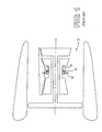
- Figure 1 is a highly schematic illustration of a
gas turbine engine 3, containing a combustor 6.Fuel 9 is sprayed into the combustor. Anigniter 12, which functions in a roughly analogous manner to a spark plug in an automobile, produces a spark, or plasma discharge (not shown), which initially ignites the jet fuel. - After initial ignition, the
igniter 12 can be repeatedly sparked thereafter, primarily as a safety measure. That is, in a modern engine, under normal circumstances, it is extremely unlikely for a flame-out to occur in the combustor 6. However, unexpected situations, such as an abrupt cross-wind, can affect the environment within the combustor, and resulting loss of flame. - In addition, certain flight conditions make the unlikely event of a flame-out slightly more probable. Thus, for example, the
igniter 12 may be activated when the aircraft enters a rain squall, or other situation which may disturb steady-state conditions in the combustor 6. - The
igniters 12, like all mechanical components, have useful lives which eventually expire, at which time the igniters must be replaced. However, this expiration-and-replacement can create a situation in aircraft which is expensive. - A primary reason is that the approach of an igniter to the end of its lifetime is not marked by readily detectable events. That is, at some point, the igniter completely ceases to generate a plasma, or spark. However, prior to that point, the igniter may sporadically generate sparks.
- As explained above, the sparking is not, in general, required to maintain the combustor flame. Consequently, the sporadic sparking would only be noticed if an actual flame-out occurred, and if the sporadic sparking were ineffective to induce a re-light. Since such a combination of events is seen as unlikely, the sporadic sparking is not readily noticed. The impending expiration of the useful life of the igniter is similarly not noticed.
- Another reason is that, while all igniters may be constructed as identically as possible, nevertheless, those igniters do not all possess the same lifetimes. Nor do all igniters experience identical events during their lifetimes. Thus, it is not known exactly when a given igniter will expire.
- Thus, the point in time when an igniter must be replaced is not known with certainty. One approach to solving this problem is to perform preventative maintenance, by replacing the igniters when they are still functioning. While the cost of a new igniter and the manpower required to install it is not great, the early replacement does impose another cost, which can be significant.
- The aircraft in which the igniter is being replaced represents a revenue source measured in thousands of dollars per hour. If the aircraft is rendered non-functional for, say, two hours during replacement of an igniter, the revenue lost during that time is substantial.
- Therefore, the uncertain lifetimes of igniters in gas turbine aircraft engines can impose significant losses in revenue.
- Normal operation of an igniter in a gas turbine engine causes erosion of an insulator inside the igniter. In one form of the invention, an auxiliary ground electrode is embedded within that insulator, and the erosion eventually exposes the auxiliary electrode. The igniter is designed so that the exposure occurs at the time when the igniter should be replaced.
- The exposed auxiliary ground electrode can be detected by the fact that, when a spark occurs, a small current travels through the auxiliary ground electrode. When that current is detected, its presence indicates the exposure. Alternately, the exposed auxiliary ground electrode can be visually detected by a human observer, perhaps by using a borescope.
- The invention will now be described in greater detail, by way of example, with reference to the drawings, in which:-
- Figure 1 is a simplified schematic of a gas turbine engine.
- Figure 2 illustrates an
igniter 12, shown in Figure 1. - Figures 3 and 4 are enlarged views of end E in Figure 2.
- Figures 5 and 6 illustrate changes in geometry of end E which the Inventors have observed.
- Figure 7 illustrates one form of the invention.
- Figures 8 and 9 are
views resembling insert 84 in Figure 7. - Figure 10 is a perspective view of part of Figure 7.
- Figure 11 is a perspective, cut-away view of one form of the invention.
- Figure 12 is a cross-sectional view of the apparatus of Figure 11.
- Figure 13 is a perspective view of the apparatus of Figure 11.
- Figure 14 illustrates one form of the invention.
- Figure 15 illustrates a sequence of events occurring in one form of the invention.
- Figure 16 illustrates two distances D9 and D10, over which two electric fields are generated.
- Figure 17 illustrates one mode of constructing
auxiliary electrode 72 in Figure 15. - Figure 18 illustrates an aircraft which utilizes one form of the invention.
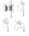
- Figure 19 illustrates
igniter 308, bearing anannular coil 310. - Figure 19A illustrates one form of the invention, wherein a bracket 311 supports
the igniter, and also contains a
coil 310. - Figure 20 illustrates an igniter-cable assembly about which is positioned a high-
permeability ring 326, about which is wrapped acoil 320. - Figure 21 is a schematic of one view of an igniter system.
- Figure 22 is a schematic developed by the Inventors of a possible mode of operation of the apparatus of Figure 21.
- Figure 23 illustrates a prior-art RLC circuit.
- Figure 24 illustrates an RLC circuit excited by a sinusoidal waveform.
- Figures 25 - 28 are plots of simulated output of the circuit of Figure 24.
- Figure 29 illustrates an RLC circuit pulsed by a pulse train.
- Figures 30 - 34 are plots of simulated output of the circuit of Figure 29.
- Figure 35 illustrates timing parameters.
- Figure 36 illustrates two forms of the invention.
-
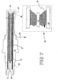
- Figure 2 illustrates an
igniter 12 used in the prior art. An electrical connector (not shown) is threaded ontothreads 21, and contains an electrical contact (not shown) which mates with theend 24 ofelectrode 27.Insulator 30 isolates electrode 27 from theshell 33 of theigniter 12. - End E of the
igniter 12 is shown in Figures 3 and 4. A very simplified explanation of the physics involved in plasma generation will be given. - In operation, a high voltage is applied to the
electrode 27, thereby creating a voltage difference, or potential difference, V between points P1 and P2 in Figure 3. The electric field in that region equals the potential difference V divided by the distance D between the points P1 and P2. For example, if the voltage is 20,000 volts and the distance D is 10 millimeters, or 0.01 meter, then the electric field equals 20,000/0.01, or 2 million volts per meter. - The electric field is designed to exceed the dielectric breakdown strength of the material, or medium, lying between points P1 and P2. That material is a mixture of air plus fuel. However, the field does not exceed the breakdown strength of
insulator 30, and that strength exceeds that of the air-fuel mixture. - When breakdown occurs, the electric field strips electrons away from the atoms in the medium, producing positively charged ions and free electrons. The electric field drives the free electrons in a direction parallel with the electric field. However, during that movement, those temporarily free electrons will collide with other ions. Also, thermal motion of the ions and electrons will also bring them together in collisions.
- In the collisions, the electrons will be captured by the ions, and will drop to a lower energy state, releasing heat and light, in the form of an electric arc which is called a plasma, which is indicated as
lightning bolt 40 in Figure 4. This process continues as long as the electric field is present. - The Inventors have observed one result of the operation just described. As indicated in Figure 5, the
insulator 30 becomes eroded from thephantom shape 50 to thecurved shape 53. In addition, theelectrode 27 becomes eroded from thephantom shape 56 to thesolid shape 59.Corners 33A also become eroded. - The Inventors believe that one or more of the following agencies are responsible for the erosion. One agency is the corrosive nature of the plasma: free electrons are very reactive, and seek to bind to any available atoms or ions which are nearby. Also, the generation of free electrons from oxygen, which is present in the air, creates ionized oxygen, which is also highly reactive.
- A third agency is that the plasma creates a high-temperature environment. A high temperature, by definition, represents agitated atoms and molecules with high velocities. High-velocity atoms and molecules react more readily with stationary objects when they collide with the objects.
- Possibly a fourth agency is the fact that the plasma generates high-frequency photons, in the ultra-violet, UV, and perhaps into the X-ray regions of the spectrum. It is well known that UV and X-radiation can damage numerous types of material.
- Irrespective of the precise causes of the erosion, the erosion illustrated in Figure 5 eventually causes the
igniter 12 to eventually stop functioning. A primary reason is illustrated in Figure 6. Previously, prior to the erosion, voltage was applied between points P1 and P2 in Figure 6. However, after the erosion, point P2 has effectively moved to point P3. Distance D has now become longer distance D2. The electric field, which causes the ionization and thus the plasma, is now weaker. - Continuing the example given above, if distance D2 is 20 millimeters, then the electric field becomes 20,000/0.020, or one million volts per meter, half its original value. Eventually, distance D2 becomes so great that the electric field does not reliably exceed the dielectric breakdown strength of the air-fuel mixture, and ionization ceases to occur.
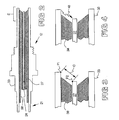
- Figure 7 illustrates one form of the invention. An
auxiliary electrode 72 is embedded in theinsulator 75. Thetip 78 is covered by the insulator-material inregion 81, as indicated by theinsert 84.Auxiliary electrode 72 may be connected to theshell 33, as atregion 90. - Initially, current enters
electrode 27 as indicated byarrow 84, jumps to theshell 33 through theplasma 85, and exits theshell 33 into the engine, through multiple paths, such as through its mounting threads, as indicated byarrow 86. - As erosion occurs, the
insulator 75 departs from its initial shape indicated byphantom lines 92 in Figure 8.Tip 78 of theauxiliary electrode 72 now becomes exposed. Now, when a high voltage is applied to the igniter, two paths exist for a plasma to follow. One is the usual path P5 in Figure 9. The other path is indicated as P6 of Figure 9, and runs from thecentral electrode 27 to the now-exposedauxiliary electrode 72. - Restated, two current-return-paths are available to the
central electrode 72. Path P5 runs to theshell 33, in the usual manner. Path P6 runs to the now-exposedauxiliary electrode 72. Eventually, further erosion will lengthen path P5, and cause plasma formation along that path to terminate. That is, path P5 in Figure 9 initially can be represented by distance D in Figure 6. After sufficient erosion, path P5 in Figure 9 will be represented by distance D2 in Figure 6, and, as explained above, no plasma will be generated along path P5 when distance D2 becomes sufficiently large. - However, auxiliary plasma path P6 is still available in Figure 9 at this time. A plasma can still be generated, and the lifetime of the igniter has been increased.
- The preceding discussion presented the
auxiliary electrode 72 in Figure 7 in the form of a rod. Figure 10 illustrates such a rod in perspective view, surrounded byinsulator 75. - In an alternate embodiment, a cylinder is used. Figure 11 is a cut-away view of one embodiment.
Central electrode 27 is surrounded by aninsulator 100, which itself is surrounded by a conductive tube orcylinder 103, which is then surrounded by another layer ofinsulator 105. Figure 12 illustrates the system in cross-sectional view, with similar numbering. - Figure 13 illustrates the
insulator 100 in its initial configuration, after manufacture or just after installation. A tip 110 ofcentral electrode 27 is exposed, and surrounded by theconical surface 113 of theinsulator 100. Cylindricalauxiliary electrode 103 is embedded within theinsulator 100, and no tip or edge is exposed, as indicated by distance D8 in Figure 12. - The preceding discussion stated that the
auxiliary electrode 72 may be connected atregion 90 in Figure 7. In another embodiment, theauxiliary electrode 72 of Figure 14 is also connected to ground, but through adetector 150.Detector 150 looks for a current inauxiliary electrode 72. Current detectors are well known. - If no current is detected, it is inferred that the
auxiliary electrode 72 is still embedded withininsulator 75, as in Figure 7, and is electrically isolated fromcentral electrode 27. - In contrast, if a current is detected, it is inferred that the auxiliary electrode has become exposed through erosion, as in Figure 9. The detected current is attributed to a plasma following path P6. When the current is detected,
detector 150 issues a signal, sets a flag, or otherwise indicates the inference that erosion has exposed auxiliary electrode. A human technician at that time, or a prescribed time afterward, replaces the igniter. - An alternate mode of detection is to remove the igniter and visually examine the end corresponding to end E in Figure 2. If a smooth surface of the
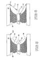
insulator 100 is seen, as in Figure 13, then it is concluded that the igniter is still functional. However, if theauxiliary electrode 72 is seen, as in Figure 8, then it is concluded that replacement may be required. - In another embodiment, the auxiliary electrode is designed to become exposed, and then to erode rapidly. Figure 15, viewed left-to-right, illustrates first a newly installed
igniter 160. After a period of usage,igniter 165 exposes itsauxiliary electrode 72. Now a plasma P6 extends to theauxiliary electrode 72. - However, as stated above, the
auxiliary electrode 72 is designed to erode rapidly. For example, asinsert 170 indicates, theauxiliary electrode 72 is fabricated with a pointed end. Plasma 6 causes the pointed end to become rapidly eroded, as indicated by the small particles inframe 170. This operation causes a specific sequence of two events. - One is that, when the auxiliary electrode becomes first exposed, a current passes through the it. The current is detected, as by
detector 150 in Figure 14. Next, after the auxiliary electrode fractures or erodes, no current passes through it. - One reason for this sequence is illustrated in Figure 16. Initially, the voltage V spans distance D9, creating an electric field equal to V/D9. After fracture or erosion, the same voltage V spans distance D10. The electric field equals V/D10, a smaller value. The latter electric field is insufficient to create a plasma, while the former is.
- In one embodiment, the occurrence of the two events just described occurs prior to the termination of the lifetime of the igniter. Thus, that termination is signaled by the occurrence of a current through the
auxiliary electrode 72, followed by a termination of that current. The onset of the current indicates the approach of the termination of the lifetime, but with time remaining to operate the engine. The subsequent termination of the current indicates that less time remains, and that replacement of the igniter becomes more important. - Figure 17 illustrates one embodiment of the
auxiliary electrode 72. A neck, or groove, 190 is provided, which facilitates the breakage schematically illustrated in theinsert 170 in Figure 15. Thegroove 190 is a region of mechanical weakness intentionally built into theauxiliary electrode 72. Prior to the erosion indicated in Figure 8, that weakness is not important, because mechanical support to the electrode is supplied by theinsulator 75. - The discussion above stated that a high voltage is applied to
electrode 27. It is possible that a low voltage applied to theelectrode 27 can accomplish the same function of generating a plasma. - Figure 18 illustrates another embodiment. An
aircraft 300 is powered by gas turbine engines (not shown), which are located withinnacelles 305. Each engine contains one, or more, igniters, as discussed above. The igniters may contain an auxiliary electrode, as described above, or may be of the prior-art type. - Figure 19 illustrates an
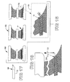
igniter 308. The invention adds a sensor, such assensing coil 310. Thiscoil 310 is coaxial with the igniter, as indicated. This particular coaxial arrangement was used in an experiment, to ascertain whether a coil could detect a signal when theigniter 308 produced a spark. - The coaxial arrangement is not necessarily required. In one form of the invention,
coil 320 can be arranged as shown in the two rightmost images in Figure 20. The magnetic field lines B produced by current I in thepower cable 315 are concentric with the current which produces the field lines B. Since that current flows though theentire cable 315, and through theigniter 308, the field lines B extend along both thecable 315 and theigniter 308. - According to Faraday's Law, optimal coupling is attained when the
coil 320 is perpendicular to the field lines B, as shown in the central image. - In another form of the invention, a high-
permeability ring 326, constructed perhaps of transformer iron, is placed about the igniter, orcable 315, and thecoil 320 is wrapped about thering 326. Thering 326 captures the magnetic field lines B, as it were, and delivers them to thecoil 320. Under this arrangement, field lines B passing through thering 326 also pass through thecoil 320. - One definition of the term high permeability is that the relative permeability of a high permeability material exceeds 1,000. As a point of reference, the relative permeability of many steels is in the range of 4,000. Materials exist having relative permeabilities approaching one million.
- In yet another form of the invention, a prior-art clamp-on current detector (not shown) is used.
- The Inventors have found that the
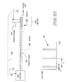
coil 310 in Figure 19, even though lacking the perpendicular characteristic shown in Figure 20, produced a detectable signal in response to current pulses within theigniter 308. The Inventors offer the following observations concerning this signal, and its detection. - Figure 21 is an electrical schematic of the igniter circuit.
Block 330 represents the exciter, which is contained within a conductive housing (not shown). Theexciter 330 produces a high-voltage pulse train, to generate spark in theigniter 340. -
Power cable 335 delivers the high-voltage current pulses to theigniter 340. One type of high-voltage pulses are in the range of 20,000 volts. One type of frequency of the pulses lies in the range of 10 Hz, that is, ten pulses per second. One type of pulse has a duration of 10 milliseconds. In this example, the duty cycle is thus ten percent (0.10/0.100). -
Plot 331 illustrates the pulses just described. Duration D would be 10 milliseconds in this example. Period T would be 100 milliseconds in this example, corresponding to a frequency of 1/T, or 10 pulses per second. - In Figure 21, a
shield 345 surrounds thepower cable 335. Theshield 345 can take the form of solid conduit, a woven conductive sleeve, a combination of the two, or other types of shielding. Thisshield 345 is connected to thecasing 350 of theigniter 340, and thecasing 350 is connected to the frame, or housing, 352 of the engine, which is considered to be a DC ground. Theshield 345 provides electromagnetic interference suppression and also prevents personnel from contacting the high-voltage cable 335. Even though thecable 335 is itself surrounded by a thick insulating cover, theshield 345 provides a redundant safety measure. - Under the arrangement illustrated, the housing (not shown) of the
exciter 330, theshield 345, and thecasing 350 of theigniter 340 are all connected to theframe 352 of the engine, and are considered to be held at DC ground. - One type of classical analysis of the apparatus shown in Figure 21 states that the following mechanism can explain the sparking operation. During each high-voltage pulse, of duration D in
plot 331, the current provided by the high-voltage cable 335 reaches thespark gap 355, jumps thegap 355, and returns via the frame of the engine, to theexciter 330, alongpath 360. Under this mechanism, arguments can be mustered indicating that thecoil 310 of the type shown in Figure 19 would be ineffective to detect the current pulses. - A basic argument is that, in theory,
coil 310 should detect no current, because no magnetic field lines B, in theory, penetrate the cross-sectional area of thecoil 310. Faraday's Law states that such penetration is required. - In considering additional arguments, two cases should be distinguished: the DC case and the AC case. In the DC case, if a DC current is carried by the high-
voltage cable 335 in Figure 21, then static magnetic field lines B of the type shown in Figure 20 would be present. If the coil is placed around the igniter as shown in Figure 19, and if thecasing 350 of the igniter is constructed of a high-permeability material, such as a type of steel, the casing will trap some, or all, of the B-field, and possibly inhibit detection of the static B-field. It could be said that the shielding, including thecasing 350 of the igniter and theshield 345, act as a Faraday cage which contains the static DC magnetic field. Thus, an argument may exist stating thatcoil 310 in Figure 19 would not detect the current pulses. - This argument may also apply to slowly varying currents. That is, it is possible that the Faraday cage also blocks slowly changing magnetic fields.
- In the AC case, electromagnetic radiation may emanate from the
cable 335 andigniter 350 in Figure 21, particularly because the current pulses contain high-frequency components. High-frequency components, in general, radiate more readily, at least from short antennas of length equal to fractions of a wavelength. The conductivity, as opposed to permeability, of theshield 345 andcasing 350 can block radiation produced by the current pulses. In one mechanism, the blockage occurs through reflection: the radiated electromagnetic field induces currents in theshield 345 andcasing 350, which radiate their own electromagnetic fields inwardly, toward thecable 335. The radiated fields, in effect, reflect the incoming radiation back to thecable 335. - Also, as stated above, the
shield 345 and igniter casing 350 are connected to ground. In theory, those grounded elements shunt all AC signals to ground, and thus prevent them from radiating electromagnetic energy. - Thus, at least the preceding arguments exist which indicate that the coil of Figure 19 would not be effective to detect current pulses in the
cable 335 of Figure 21. - The Inventors have observed, or postulated, that all the return current may not follow
path 360 in Figure 21. Return current refers to that returning to theexciter 330 after having jumped thespark gap 355. The Inventors surmised that some return current may travel along the shielding system, including theshield 345 and thecasing 350 in Figure 21. Figure 22 is one representation of this surmise. - Resistor R1 indicates the small resistance of the ground path through the engine frame, from the
spark gap 355 to the exciter, and corresponds roughly topath 360 in Figure 21. Resistor R2 indicates the small resistance of the path from thespark gap 355 to the exciter, but through the shield system. The shield system includes thecasing 350 of the igniter and theshield 345. Both R1 and R2 originate at, or near, thespark gap 355, but represent different routes to theexciter 330. - Under this surmise, it is possible that the return current passing through R2 is detectable, despite the arguments given above.
- In this context, the Inventors point out that, in general, detecting a return current through the other resistor R1 is considered impractical. Resistor R1 represents, among other things, the engine itself. A simple, accurate, and reliable approach to detecting return current in the engine is not seen as practical, at least for the reason that the number of paths available to the return current is so large, in spanning the entire engine, or a large part of it.
- However, the path represented by resistor R2 is a localized, discrete entity, from a current-detection standpoint, and is not contained within a shield. Thus, if a return current pulse is travelling in R2, then the magnetic field, or electromagnetic radiation, produced by the pulse may be detectable, by detecting the current in R2, that is, the current in the shield system.
- An experiment was undertaken, using
coil 310 in Figure 19, and it was found thatcoil 310 produced a detectable signal, when the exciter produced a spark pulse. - It should be observed that the
coil 310 may be detecting one, or more, of the following currents.Coil 310 may be detecting the current pulse in thecable 335 in Figure 21, contrary to the arguments given above: the shielding system may not be completely effective. Alternately,coil 310 in Figure 19 may be detecting return current pulses in thecasing 350 of the igniter, as postulated above. Orcoil 310 may be detecting some type of sum or difference of the two currents just identified. - The signal detected in
coil 310 was small, so that amplification may be desired. However, the operational environment of thecoil 310 provides a challenge in this respect. - During operation of the
aircraft 300 of Figure 18,coil 310 in Figure 19 will be located in an environment having a temperature exceeding 400 F. That is, thecasing 350 of theigniter 308 in Figure 19, to which thecoil 310 is attached or adjacent, exhibits a temperature of at least 400 F during normal operation. - Such a high temperature would cause problems if a solid-state amplifier is to be used to amplify signals produced by
coil 310. Nevertheless, with sufficient precautions, an electronic, transistorized amplifier could be used to detect the signals produced by thecoil 310. - In one form of the invention, no solid-state amplifier is used, at least not in the vicinity of the 400 degree environment. Instead, a passive amplifier was developed, using only resistive, capacitive, and inductive elements, with no active elements such as transistors or vacuum tubes. One definition of active element is that an active element can amplify power of an input signal: output power can exceed input power. A passive element does not possess that property of power amplification.
- It is known that a series RLC circuit, such as that in Figure 23, can be designed to produce an amplified voltage across the capacitor C under certain conditions. This amplification is discussed in Chapter 13, entitled "Frequency Response," in the text entitled "Engineering Circuit Analysis," by William Hayt and Jack Kemmerly (ISBN 0-07-027410-X, McGraw-Hill, 1993). This text is hereby incorporated by reference.
- The conditions for amplification include the following. One, the signal source, Vin, be sinusoidal, and of constant frequency, which is a situation often called sinusoidal steady-state. Two, the values of the capacitor C and inductor L are chosen so that the input impedance seen at points P1 and P2 is purely real, with no reactive components. This condition is called resonance, and the value of the resonance frequency, omega-sub-zero, is indicated in Figure 23.
- Under these conditions, the voltage across the capacitor, Vc, will equal ABS(Q) x Vin, as indicated in Figure 23, wherein ABS refers to the absolute value, or magnitude, of the Quality factor Q of the circuit. Q is defined as indicated in Figure 23. Thus, for example, for a Q of 10, a tenfold amplification is attained.
- Thus, the prior art indicates that a series RLC circuit can provides voltage amplification to a sine wave input. The text identified above indicates that the dual of a series RLC circuit, namely, a parallel RLC circuit, provides current amplification, as opposed to voltage amplification.
- A computer simulation will illustrate the voltage amplification.
- Figure 24 illustrates a circuit which was simulated using one of the commercially available SPICE programs. The
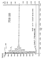
transformer 372 is present, in order to make this circuit consistent with the circuit models of the invention, later discussed. Values of the resistor R, capacitor C, and inductor L are indicated. These values remained constant in all simulations. - Figures 25 - 28 illustrate results of four simulations done on the circuit of Figure 24. An input signal, lin in Figure 24, was applied, in the form of a two-amp peak-to-peak sinusoid, which is shown in the Figures. The frequency of the input signal was changed in each simulation.
- In Figure 25, the input frequency was 50 Hz. The left axis applies to the input signal lin. The right axis applies to the voltage across the capacitor, Vc, which is indicated in Figure 25. It is clear that, at 50 Hz, the output Vc is a sinusoid of about 200 volts, peak-to-peak.
- In Figure 26, the input frequency was 750 Hz. It is clear that, at 750 Hz in Figure 26, output Vc is a sinusoid of about 3,200 volts, peak-to-peak.
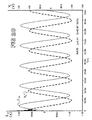
- The resonance frequency of Figure 24 is about 2517 Hz, computed using the expression for omega-sub-zero given in Figure 23. In Figure 27, the input frequency was 2517 Hz. It is clear that, at 2517 Hz, Vc is a sinusoid of about 32,000 volts, peak-to-peak.
- In Figure 28, the input frequency was 50 kHz, that is, 50,000 Hz. It is clear that, at 50 kHz, Vc is a sinusoid of about 200 volts, peak-to-peak.
- Figures 25 - 28 are consistent with the postulate that a series RLC circuit can amplify a steady-state sinusoid. At the resonant frequency, Vc is high, 32,000 volts at resonance, and at other frequencies, Vc is lower. It is emphasized that Figures 25 - 28 do not represent voltages produced by
coil 310 in Figure 19, but capacitor C in Figure 24, under the assumed conditions. - The Inventors investigated whether an RLC circuit of the type shown in Figure 24 can produce a similar amplification when the input signal is not a steady-state sinusoid, but a train of pulses of the type used to power the igniters discussed herein. Experimental results indicate an affirmative answer, and the computer simulations to be discussed provide plausibility arguments.
- In Figure 29,
coil 370 represents thepower cable 315. The power cable is actually a single-turn device, butcoil 370 in Figure 24 is represented as a multi-turn device, in order to emphasize the usage of the power cable as the primary of atransformer 373. -
Coil 375 represents the pick-upcoil 310 of Figure 19, but coils resemblingcoil 320 in Figure 20 could be used. In Figure 29, capacitor C and resistor R are elements added to thesensing coil 375, in the pursuit of amplification. It is emphasized that the elements of the circuit of Figure 29 are chosen to withstand operating temperatures consistent with the environment in which they will be used, particularly temperatures, and also vibration. - The Inventors have found that, for a given pulse train, an artificial resonance frequency can be first computed. Then, in one approach, the artificial resonance frequency is treated as an ordinary sinusoidal steady-state resonance frequency, corresponding to omega-sub-zero in Figure 23. Using the artificial resonance frequency, values of inductor L and capacitor C are chosen in the usual manner, but recognizing that (1) an artificial resonance frequency is being used and (2) steady-state sinusoidal resonance will not apply. Instead, the L and C values obtained are used with a pulsed input.
- In practice, the value of inductor L may be fixed by the materials and geometry of used to construct
coil 310 in Figure 19, so that the only value under control of the designer would be that of capacitor C. - Once the values of L and C are chosen, based on the artificial resonance frequency, it is found that amplification of a pulse train applied to
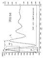
transformer 372 in Figure 29 can occur. - Alternately, the artificial resonance frequency can be determined graphically, and this will be illustrated by a sequence of examples. Figure 30 illustrates simulation output of the circuit of Figure 29, but when excited by the input signal 400 in Figure 30, which is a triangular current pulse, which is applied to
coil 370 in Figure 24. The component values used in Figure 25 for the current simulation were the following: R of 500 ohms, L of one Henry, and C of 0.40 microFarads, as indicated in Figure 30. - The horizontal axis indicates time, in units of milliseconds. As before, the left axis applies to the input signal, and the right axis applies to the output signal, which is the voltage across capacitor C in Figure 24.
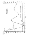
- Figure 30 indicates that the output is a decaying sinusoid which first peaks at about positive 250 volts, at
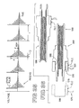
point 405, then peaks at about negative 175 volts, atpoint 410, and so on. This output response is commonly called an underdamped response in an RLC circuit, and is also called ringing. - Figure 31 illustrates a simulation using the same triangular input, and the same component values as in Figure 30, with the exception that capacitor C is one-tenth its previous value, and is now 0.040 microFarads. It is seen that the response frequency increases, consistent with the reduction of the value of C. Further, the amplitude of Vc has increased: it now peaks at about 2.4 kvolts, at
point 415. - Figure 32 illustrates a simulation using the same triangular input, and the same component values as in Figure 31, with the exception that inductor L has been cut in half, and is now 0.5 Henry. It is seen that the response frequency increases, consistent with the reduction of the value of L. Further, the amplitude of Vc has increased: it now peaks at about 2.8 kvolts, at
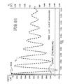
point 420. - Figure 33 illustrates a simulation using the same triangular input, and the same component values as in Figure 32, with the exception that inductor L has been cut to 20 percent of its previous value, and is now 0.1 Henry. It is seen that the response frequency increases, consistent with the reduction of the value of L. Further, the amplitude of Vc has increased: it now peaks at about 3.3 kvolts, at
point 425. - Figure 34 is an expanded view of Figure 33, spanning from zero to 2.0 milliseconds, and illustrates one concept of the artificial resonance frequency. Time T illustrates the period of the response. The response frequency F, in Hz, is of
course 1/T. F is the resonance frequency of the circuit, and is defined in Figure 24. - Figures 30 - 34 illustrate a graphical approach to selecting an artificial resonance frequency. In a sense, one selects values of L and C to attain an output waveform, as in Figure 34, wherein the upper half of the first sine wave resembles the input waveform. For example,
upper half 425 somewhat resembles the input wave form. Alternately, a more mathematical approach can be used. - In Figure 34, the value T/2 can be termed the half-period of the circuit's resonance frequency. T/2 is the duration of one positive-going, or one negative-going, hump of the decaying sine wave. The Inventors point out that, in the sequence of Figures 30 - 34, as T/2 of Figure 34 approaches the duration TT in
- Figure 34 of the triangular input pulse, voltage amplification increases. That is, as T/2 approaches duration TT, by changing the values of L and C in Figure 24, capacitor voltage Vc increases.
- This illustrates one approach to setting the artificial resonance frequency. Inductor L and capacitor C are selected so that they produce a resonance frequency having a half-period T/2 equal to the duration TT of the input pulse. But the input is pulsed, or in the case of the simulations of Figures 30 - 34, triangular.
- This computation can also be used if the input pulse is a rectangular pulse, and not the triangular pulse shown. The duration of the input pulse, such as D in
plot 331 in Figure 21, is taken as corresponding to duration TT in Figure 34. Duration D then corresponds to a frequency of 1/D, in Hz. That frequency is taken as the artificial resonance frequency, and the needed L and C are computed, using the equations given in Figure 23, with suitable conversion to radian measure. - In another approach, the artificial resonance frequency is chosen based on the rise time, or fall time, of the input pulse. In Figure 34, rise time is about one microsecond, and is the time to rise from
point 430 topoint 435. The artificial resonance frequency is chosen so that T/4, that is, one-fourth of a period T, equals the rise time. Values for L and C are chosen accordingly. - A similar principle applies to the fall time.
- The input pulse may be a rectangular pulse. Of course, the pulse will not be perfectly rectangular: the leading and trailing edges will necessarily have finite rise and fall times. The artificial resonance frequency is chosen so that T/4, namely, the quarter-period time, equals the rise time, analogous to the triangular case.
- It is pointed out that the artificial resonance frequency is largely determined by the period D in Figure 1. However, period D is not a frequency of the pulse train. Rather, the frequency equals 1/T. Thus, the artificial resonance frequency, and thus the values of L and C computed from that frequency, do not depend completely on the input frequency, but also on the duty cycle of the pulse train.
- The preceding approaches discussed selecting an artificial resonance frequency, based on timing of input pulses. In yet another form of the invention, the artificial resonance frequency is determined by trial-and-error. Simulations are run, as by experimenting with the actual circuit shown in Figure 24, or by using computer software such as SPICE, which simulate that circuit. Various values of L and C are selected, and those providing the desired amplification are then used.
- However, the sizes of L and C can be limited by practical considerations. For example, in a given situation, attainment of resonance may require a capacitor which is extremely large in physical size. Thus, in some situations, components can be chosen to provide operation at a non-resonant condition, but still provide adequate amplification.
- It is pointed out that the computer simulation approach can be very simple, given that many SPICE programs allow parameters to be swept. That is, in sweeping, a range of values for a parameter, such as L, is selected, and the number of values to be used in the range is specified. In sweeping, literally thousands or millions of different values of L, and also C, can be selected and tested, all using a computer program, with little or no human effort.
- A human then examines the results and chooses those desired.
- At the artificial frequency, values of L and C are computed which provide specific impedances. Those impedances are the phasor impedances computed as if the excitation were steady-state sinusoidal. That is, at the artificial resonant frequency, the sum of the impedances of L and C are set to zero.
- That is, jwL + 1/jwC = 0, wherein
- L is the inductance,
- C is the capacitance,
- w is the pseudo-resonant frequency, and
- j is the imaginary operator.
-
- Once w is chosen, L and C are selected to satisfy the equation given in the preceding sentence.
- Thus, the desired values of L and C are computed as though the system were operating in a steady-state sinusoidal mode, but then L and C are used in a pulsed input mode.
- In addition, the value of R can be important. In one form of the invention, the RLC circuit of Figure 24 is designed to exhibit an underdamped response, in the engineering sense, so that excitation by a pulse will induce the sinusoidal response called ringing. The envelope of the sinusoid decays exponentially. The value of R determines the speed of decay. In one form of the invention, R is chosen so that the following events occur.
- First, a current pulse generates a spark. That pulse excites the RLC circuit, such as that shown in Figure 29. The RLC circuit goes into ringing, as indicated in Figures 31 - 34. But the R is selected so that the ringing sinusoid decays sufficiently before the next pulse, so that the next ringing sinusoid can be distinguished from the current one.
- In one embodiment, the ringing sinusoid in Figure 35 decreases to 50 percent of its original amplitude A within 1/2 T. Also contemplated is a decrease to 50 percent within any selected time between 0.05 and 0.9 T.
- U.S. Patent 5,523,691, June 4, 1996, Application Number 458,091, issued to Frus, illustrates one approach to detecting spark in an igniter in an aircraft engine. Frus states that inductor L1 in his Figure 1A is first charged by a current. When a normal spark occurs, the inductor L1 rapidly discharges through the IGNITER PLUG.
- However, if the IGNITER PLUG does not produce a spark, then the inductor L1 sees the IGNITER PLUG as a very high resistance. In this case, inductor L1 discharges through a resistor contained within
voltage divider 27. This latter discharge requires a significantly longer time. Frus detects the length of the discharge, and when the longer discharge is detected, he infers the absence of spark. - Frus also states that spark can fail to occur if the voltage produced by exciter 13 falls short of the intended value. Frus discusses an approach to detecting this failure.
- The Inventors point out that the inductor L1 in Frus does not serve a similar purpose to the
coil 310 in Figure 19 herein. For example, Frus' inductor L1 carries current which is delivered to the IGNITER PLUG. In contrast,coil 310 does not do that. - Another difference is that Frus' inductor L1 must be designed to withstand voltages which certainly exceed 1,000 volts, and probably exceed 20,000 volts. Thus, significant insulation is required between the input and output leads extending from the physical inductor L1, as well as around the coiled wire within the device. In contrast,
coil 310 of Figure 19 must withstand a few volts. In one embodiment,coil 310 is designed as an inductor with an operating voltage on its two leads of no more than 5, 10, or 100 volts, in three different embodiments. - In addition, the inductor L1 of Frus does not seem to be present in an environment where the temperature exceeds 400 F.
- In one form of the invention, a specific starting sequence is used when the gas turbine engine is started, as in the aircraft shown in Figure 18. The pilot causes a starting system to rotate the rotor (not shown) of the engine, or orders a control system (not shown) to initiate a start-up routine. A fuel control (not shown) delivers fuel to the combustor. The igniters in the combustors are actuated.
- If light-off of the engine is not detected, the pilot then examines an
indicator 500 in Figure 18.Indicator 500 is located at the pilot's station in the aircraft, often called the cockpit. That indicator receives a signal from adetector 505, which responds to the voltage signal produced by capacitor C in Figure 19, which will be termed a spark signal. If the spark signal indicates that the igniter is producing sparks, then theindicator 500 indicates the presence of spark, as by producing a light. If the spark signal is absent, then theindicator 500 indicates the absence of spark, as by producing no light. - From another perspective, the
indicator 500 operates oppositely to an analogous indicator in an automobile. The oil-pressure indicator light in an automobile, for example, illuminates when a problem occurs. In contrast, theindicator 500 illuminates when a problem is absent, namely, when the igniter is producing spark. - A
switch 510 can be provided, to allow the pilot to turn off theindicator 500 when knowledge of spark is not desired. Alternately, a control system, not shown, can control when theindicator 500 displays its information. - Figure 36 illustrates two forms of the invention. The
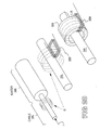
igniter 550 has aproximal end 555 and adistal end 560. The proximal end has ahousing 565, which, in this instance, is of cylindrical shape, or circular shape in cross-section. Other cross-sectional shapes are possible. - A
detachable housing 570 is shown, which contains coil L, capacitor C, and resistor R, analogous to the corresponding elements in Figure 29, and indicated by block RLC. Connectors, wiring leads,coaxial cable 575 or the like allow external detection of a voltage across capacitor C, or other selected component. -
Housing 570 contains anaperture 580 of a cross-sectional shape which matches that of thehousing 565. Matching shape means that the two shapes are the same shape, and the same size, so that theaperture 580 fits snugly about thehousing 565. - In one form of the invention, the inductor L is wrapped about the axis of the igniter, as in Figure 19. In another form of the invention, a high-permeability ring surrounds the igniter, and captures the magnetic field B produced by current entering the igniter. The inductor L is wrapped around the ring, as in Figure 20.
- In another form of the invention, the spark detector RLC is made integral with the igniter, as shown in
igniter 600 in Figure 36. - Several additional aspects of the invention are the following. In one form of the invention, an adapter 311 in Figure 19A is provided which mounts to the engine or combustor (neither shown). The igniter threads into the adapter. The adapter contains
integral coils 310 which perform the detection function described above. - It is not necessary that the RLC circuit operate at resonance. Rather, the RLC circuit can be viewed as performing two functions. One is that it amplifies the pulse generated in the inductor, L. A second is that the RLC circuit produces ringing, or a decaying sinusoid. The ringing causes the detected signal to persist over a longer time than the pulse inducing the ringing, thereby making the pulse easier to detect.
- The triangular wave shown for example in Figure 34 is diagrammatic. The actual signal used in the igniter need not be triangular, but will depend on the requirements of the particular igniter used. Also, the physical properties of the igniter change as it ages, and those properties affect the shape of the pulse applied to it. By analogy, it is well known that, in a capacitor, the current is not in phase with an applied AC voltage. The internal resistance of the capacitor may change with age. That change will cause a change in the phase angle between the current and the voltage, thus illustrating the point that a change in a physical object to which a voltage is applied can change the resulting current in the object.
- The discussion herein was framed in terms of discrete, lumped circuit elements, such as the R, L and C in Figure 24. However, it is observed that similar results can be obtained with distributed elements.
- The application to gas turbine engines in aircraft discussed above is exemplary. In general, the invention is applicable to gas turbines generally, which are used in aircraft, land vehicles, ships, power generation, and other applications. Further, the invention is applicable to spark detection in igniters generally.
- A bleed resistor can be added to bleed charge from capacitor C in Figure 24, and the corresponding capacitor in the RLC circuit. The bleed resistor sharpens the decay of the ringing, thus causing the ringing to die out faster.
- In general, the values of R, L, and C are chosen to provide a detectable signal, such as on capacitor C. One definition of detectable signal can be obtained with reference to K-type thermocouples, which are used extensively in gas turbine engines. Such thermocouples produce signals in the range of 250 millivolts. Thus, one definition of a detectable signal can be a signal exceeding 250 millivolts. Consistent with that definition, in one experiment, the inventors obtained a signal of 470 millivolts across the capacitor C.
- One feature of the invention is that it allows the capacitor in the RLC circuit to be positioned remotely from the other components, and thus in a cooler location than the location of the
coil 310 in Figure 19. In one embodiment, the capacitor C can be positioned in a room-temperature environment, or cooler, where room temperature is taken as nominally 75 degrees F. - This can be significant because many capacitors have a practical temperature limit of 175 degrees F. But the location of
coil 310 in Figure 19 will probably exceed 400 degrees F. - The discussion above referred to delivering a signal indicating proper spark is occurring to a pilot station. This signal could also be delivered to maintenance personnel, either in the apparatus which utilizes the gas turbine engine, or to remote maintenance personnel. The signal can also be delivered to more than one pilot station.
- Numerous substitutions and modifications can be undertaken without departing from the true spirit and scope of the invention. For example, the discussion above was framed in terms of aircraft gas turbine engines. However, the invention can be used in other types of gas turbines, such as land-based gas turbine engines used in power generation and pumping, or in ships. In addition, the invention is not restricted to gas turbine engines, but can be used in igniters generally, which are used in various combustion applications.
- Also, it is not required that the invention be operated in a hot environment, but the invention does provide the ability to withstand high-temperatures, as explained above.
- For the sake of good order, various aspects of the invention are set out in the following clauses: -
- 1. Apparatus for sensing spark (40) in an igniter (340) in a gas turbine
engine (3), comprising:
- a) a holder (311) into which the igniter (340) is inserted;
- b) a coil (310) mounted in the holder; and
- b) a detector (150) for detecting current in the coil (310).
- 2. Apparatus according to
clause 33, wherein said holder (311) reaches a temperature of 175 °F or greater during normal operation of the engine (3). - 3. Apparatus according to
clause 1, wherein the coil (310) is in thermal contact with the igniter (340). - 4. Apparatus according to
clause 1, wherein said holder (311) is conductive and held at a system ground. - 5. Apparatus according to
clause 2, wherein no electrical current passing through the igniter (340) enters the coil (310). - 6. Apparatus according to
clause 1, wherein (1) a cable (335) runs from an exciter (330) to the igniter (340), (2) the cable (335) delivers electrical power to the igniter (340), (3) an external conductive shield (345) surrounds the cable (335) and is connected to the engine (3), and (4) the cable (335) connects to the igniter (340) at a contact point, and a second conductive shield (350) extends from the contact point along the igniter (340), and wherein - d) the coil (310) is wholly external to both conductive shields (345, 350).
- 7. Apparatus according to
clause 1, wherein part of the igniter (340) forms a core of the coil (310). - 8. Apparatus according to clause 6, wherein the second conductive shield (350) comprises a housing of the igniter (340).
- 9. Apparatus for attaching an igniter (340) to a gas turbine engine (3),
comprising:
- a) a base (311) containing a threaded bore, into which bore the igniter (340) can be threaded;
- b) holes in the base through which fasteners can fasten the base (311) to the engine; and
- c) a coil (310) affixed to the base (311), for detecting currents in the igniter (340).
- 10. Apparatus for attachment to an igniter (340) for a gas turbine engine (3),
the igniter (340) having (1) a proximal end (555), (2) a casing (565) at the
proximal end (555), the casing (565) having a cross sectional shape S, and (3)
an electrical connector at the proximal end, the apparatus comprising:
- a) a housing (570) having an internal aperture (580) matching shape S, so that the housing (570) fits about the proximal end (555);
- b) within the housing (570),
- i) an inductive pick-up (L), and
- ii) an amplifier (R, C) which amplifies signals produced by the pick-up (L).
- 11. Apparatus according to clause 10, wherein the inductive pick-up (L) is in thermal contact with the casing (565), when the housing (570) is fitted about the proximal end (555).
- 12. Apparatus according to clause 10, wherein the amplifier comprises an RLC amplifying circuit.
- 13. Apparatus according to
clause 12, wherein the igniter (340) is powered by non-sinusoidal voltage pulses of frequency F, with each pulse having a duration D, and the RLC resonant circuit is resonant to sinusoidal steady-state excitation of afrequency 1/2D. - 14. Apparatus according to clause 13, wherein the non-sinusoidal voltage pulses are substantially triangular.
- 15. Apparatus according to clause 13, and further comprising a ring of high permeability material which surrounds the igniter when the housing is fitted to the igniter, and a magnetic field produced by current passing through the connector travels through both the high permeability material and the inductive pick-up.
- 16. Apparatus, comprising:
- a) an igniter (340) for a gas turbine engine (3);
- b) an inductive pick-up (310) adjacent the igniter (340); and
- c) an amplifier (R, C) having no active elements, which amplifies signals produced by the pick-up (L).
- 17. Apparatus according to clause 16, wherein the pick-up (310) produces signals when the igniter (340) produces sparks (40).
- 18. Apparatus according to clause 16, wherein the amplifier comprises an RLC resonant circuit.
- 19. Apparatus according to clause 18, wherein the igniter (340) is powered
by non-sinusoidal voltage pulses of frequency F, with each pulse having a
duration D, and the RLC resonant circuit is resonant to sinusoidal steady-state
excitation of a
frequency 1/2D. - 20. Apparatus according to clause 16, wherein the amplifier contains no active elements.
-
Claims (10)
- Apparatus for sensing spark (40) in an igniter (340) in a gas turbine engine (3), comprising:a) a holder (311) into which the igniter (340) is inserted;b) a coil (310) mounted in the holder; andc) a detector (150) for detecting current in the coil (310).
- Apparatus according to claim 33, wherein said holder (311) reaches a temperature of 175 F or greater during normal operation of the engine (3).
- Apparatus according to claim 1, wherein the coil (310) is in thermal contact with the igniter (340).
- Apparatus according to claim 1, wherein said holder (311) is conductive and held at a system ground.
- Apparatus according to claim 2, wherein no electrical current passing through the igniter (340) enters the coil (310).
- Apparatus according to claim 1, wherein (1) a cable (335) runs from an exciter (330) to the igniter (340), (2) the cable (335) delivers electrical power to the igniter (340), (3) an external conductive shield (345) surrounds the cable (335) and is connected to the engine (3), and (4) the cable (335) connects to the igniter (340) at a contact point, and a second conductive shield (350) extends from the contact point along the igniter (340), and whereind) the coil (310) is wholly external to both conductive shields (345, 350).
- Apparatus according to claim 1, wherein part of the igniter (340) forms a core of the coil (310).
- Apparatus according to claim 6, wherein the second conductive shield (350) comprises a housing of the igniter (340).
- Apparatus for attaching an igniter (340) to a gas turbine engine (3), comprising:a) a base (311) containing a threaded bore, into which bore the igniter (340) can be threaded;b) holes in the base through which fasteners can fasten the base (311) to the engine; andc) a coil (310) affixed to the base (311), for detecting currents in the igniter (340).
- Apparatus for attachment to an igniter (340) for a gas turbine engine (3), the igniter (340) having (1) a proximal end (555), (2) a casing (565) at the proximal end (555), the casing (565) having a cross sectional shape S, and (3) an electrical connector at the proximal end, the apparatus comprising:a) a housing (570) having an internal aperture (580) matching shape S, so that the housing (570) fits about the proximal end (555);b) within the housing (570),i) an inductive pick-up (L), andii) an amplifier (R, C) which amplifies signals produced by the pick-up (L).
Applications Claiming Priority (2)
| Application Number | Priority Date | Filing Date | Title |
|---|---|---|---|
| US775847 | 1996-12-31 | ||
| US10/775,847 US7093422B2 (en) | 2004-02-10 | 2004-02-10 | Detecting spark in igniter of gas turbine engine by detecting signals in grounded RF shielding |
Publications (2)
| Publication Number | Publication Date |
|---|---|
| EP1564491A2 true EP1564491A2 (en) | 2005-08-17 |
| EP1564491A3 EP1564491A3 (en) | 2005-11-23 |
Family
ID=34701343
Family Applications (1)
| Application Number | Title | Priority Date | Filing Date |
|---|---|---|---|
| EP20050250751 Withdrawn EP1564491A3 (en) | 2004-02-10 | 2005-02-09 | Detecting spark in igniter of gas turbine engine by detecting signals in grounded shielding |
Country Status (4)
| Country | Link |
|---|---|
| US (1) | US7093422B2 (en) |
| EP (1) | EP1564491A3 (en) |
| JP (1) | JP4681904B2 (en) |
| CN (1) | CN100523455C (en) |
Cited By (4)
| Publication number | Priority date | Publication date | Assignee | Title |
|---|---|---|---|---|
| WO2007054774A2 (en) * | 2005-11-03 | 2007-05-18 | Neq Lab Holding Inc. | Ignition and combustion method by means of pulsed periodic nanosecond high-voltage discharge |
| WO2015171719A1 (en) * | 2014-05-06 | 2015-11-12 | Woodward, Inc. | Localized ignition diagnostics |
| FR3100392A1 (en) * | 2019-08-28 | 2021-03-05 | Safran Aircraft Engines | Turbomachine spark plug wear monitoring by visual identification of differential wear |
| EP3835658A1 (en) * | 2019-12-10 | 2021-06-16 | General Electric Company | Combustor ignition timing |
Families Citing this family (10)
| Publication number | Priority date | Publication date | Assignee | Title |
|---|---|---|---|---|
| US20090165436A1 (en) * | 2007-12-28 | 2009-07-02 | General Electric Company | Premixed, preswirled plasma-assisted pilot |
| US10137542B2 (en) | 2010-01-14 | 2018-11-27 | Senvion Gmbh | Wind turbine rotor blade components and machine for making same |
| BR112012017122B1 (en) | 2010-01-14 | 2021-09-28 | Senvion Gmbh | COMPOSITE BEAM FOR A WIND TURBINE SHOVEL |
| US9086018B2 (en) | 2010-04-23 | 2015-07-21 | Hamilton Sundstrand Corporation | Starting a gas turbine engine to maintain a dwelling speed after light-off |
| US10473033B2 (en) * | 2016-10-19 | 2019-11-12 | Honeywell International Inc. | Gas turbine engine |
| US10894610B2 (en) * | 2017-06-05 | 2021-01-19 | The Boeing Company | Jet stream lightning protection apparatus, system, and method the same |
| CN109059044A (en) * | 2018-07-13 | 2018-12-21 | 湖南云顶智能科技有限公司 | A kind of supporting plate spray burner and ignition method being provided with pulse firing source |
| CN111521939B (en) * | 2020-05-15 | 2021-05-14 | 杭州核诺瓦科技有限公司 | Device and method for nondestructive testing of transient characteristics of conductive screw of steam turbine generator rotor |
| US11229113B1 (en) | 2020-08-12 | 2022-01-18 | Metrolaser, Inc. | Discharge cell systems and methods |
| KR102520679B1 (en) * | 2021-07-08 | 2023-04-11 | (주)고려엔지니어링 | A Device for ignition using plasma |
Family Cites Families (29)
| Publication number | Priority date | Publication date | Assignee | Title |
|---|---|---|---|---|
| US2969500A (en) * | 1957-08-02 | 1961-01-24 | Frank S Andert | Spark plug and ignition indicator system therefor |
| GB998371A (en) * | 1964-05-04 | 1965-07-14 | Rolls Royce | Ignition means for a continuous flow engine |
| DE2236187A1 (en) * | 1972-07-24 | 1974-02-21 | Kapsch Telephon Telegraph | CIRCUIT ARRANGEMENT FOR ELECTRONIC MONITORING OF THE IGNITION FUNCTION OF A COMBUSTION ENGINE |
| US3967149A (en) * | 1973-07-05 | 1976-06-29 | Champion Spark Plug Company | Spark plug |
| DE2343895A1 (en) * | 1973-08-31 | 1975-03-13 | Bosch Gmbh Robert | PROCEDURE AND EQUIPMENT FOR CHECKING IGNITION SYSTEMS IN COMBUSTION ENGINEERING MACHINES |
| US4090125A (en) * | 1977-02-22 | 1978-05-16 | Ambac Industries, Incorporated | Ignition indicator for internal combustion engines |
| US4284054A (en) * | 1979-07-23 | 1981-08-18 | Tokai Trw & Co. Ltd. | Lean air-fuel mixture attraction method and attraction electrode plug in engine |
| JPH0831352B2 (en) * | 1987-08-04 | 1996-03-27 | 株式会社日本自動車部品総合研究所 | Spark plug |
| US4814664A (en) * | 1988-02-16 | 1989-03-21 | Champion Spark Plug Company | Igniter with wear indicator |
| US5155437A (en) | 1990-07-26 | 1992-10-13 | Unison Industries Limited Partnership | Diagnostic device for gas turbine ignition system |
| US5523691A (en) | 1990-07-26 | 1996-06-04 | Unison Industries Limited Partnership | Diagnostic device for gas turbine ignition system |
| US5221904A (en) * | 1991-03-07 | 1993-06-22 | Honda Giken Kogyo Kabushiki Kaisha | Misfire-detecting system for internal combustion engines |
| NL9101257A (en) * | 1991-07-17 | 1993-02-16 | Deltec Fuel Systems Bv | SPARK BRACKET ELECTRODES MEASURING AND MONITORING DEVICE. |
| US5194813A (en) | 1991-09-16 | 1993-03-16 | Hannah Kenneth H | Spark ignition analyzer |
| GB2269020A (en) * | 1992-07-25 | 1994-01-26 | Econocruise Ltd | Ignition monitoring system |
| US5508618A (en) * | 1993-07-15 | 1996-04-16 | Simmonds Precision Engine Systems | Coreless detector for ignition dischage current |
| US5587630A (en) * | 1993-10-28 | 1996-12-24 | Pratt & Whitney Canada Inc. | Continuous plasma ignition system |
| DE4340616A1 (en) * | 1993-11-29 | 1995-06-01 | Bmw Rolls Royce Gmbh | Spark plug fastener on gas turbine combustion chamber housing |
| US5572135A (en) * | 1993-12-27 | 1996-11-05 | Simmonds Precision Engine Systems | Diagnostic apparatus and methods for ignition circuits |
| DE4422939C2 (en) | 1994-06-30 | 2000-05-31 | Bosch Gmbh Robert | Spark plug for an internal combustion engine |
| US5606118A (en) | 1995-09-05 | 1997-02-25 | Ford Motor Company | System and method for detecting misfire in an internal combustion engine |
| US5892319A (en) | 1996-01-04 | 1999-04-06 | Rossi; Paul | Top and side firing spark plug |
| DE19818214A1 (en) | 1998-04-24 | 1999-10-28 | Bosch Gmbh Robert | Spark plug for combustion engine |
| US6232703B1 (en) * | 1998-12-22 | 2001-05-15 | General Electric Company | Multiple electrode igniter |
| DE19905771A1 (en) | 1999-02-12 | 2000-08-17 | Bosch Gmbh Robert | spark plug |
| US6222445B1 (en) * | 1999-05-06 | 2001-04-24 | Micro Technology Services, Inc. | Engine monitoring system and associated method |
| KR20010084423A (en) * | 2000-02-25 | 2001-09-06 | 김순택 | Beam index type cathode ray tube |
| US6505605B2 (en) | 2000-03-29 | 2003-01-14 | Ngk Spark Plug Co., Ltd. | Control system for an internal combustion engine and method carried out by the same |
| TW534983B (en) * | 2001-07-31 | 2003-06-01 | Snap On Tech Inc | Coil on plug inductive sampling method and apparatus |
-
2004
- 2004-02-10 US US10/775,847 patent/US7093422B2/en not_active Expired - Fee Related
-
2005
- 2005-02-08 JP JP2005031545A patent/JP4681904B2/en not_active Expired - Fee Related
- 2005-02-09 EP EP20050250751 patent/EP1564491A3/en not_active Withdrawn
- 2005-02-16 CN CNB2005100090297A patent/CN100523455C/en not_active Expired - Fee Related
Non-Patent Citations (1)
| Title |
|---|
| None |
Cited By (6)
| Publication number | Priority date | Publication date | Assignee | Title |
|---|---|---|---|---|
| WO2007054774A2 (en) * | 2005-11-03 | 2007-05-18 | Neq Lab Holding Inc. | Ignition and combustion method by means of pulsed periodic nanosecond high-voltage discharge |
| WO2007054774A3 (en) * | 2005-11-03 | 2007-09-13 | Neq Lab Holding Inc | Ignition and combustion method by means of pulsed periodic nanosecond high-voltage discharge |
| WO2015171719A1 (en) * | 2014-05-06 | 2015-11-12 | Woodward, Inc. | Localized ignition diagnostics |
| US9822708B2 (en) | 2014-05-06 | 2017-11-21 | Woodward, Inc. | Igniter event conductor for conducting igniter events from a combustion chamber to a sensor |
| FR3100392A1 (en) * | 2019-08-28 | 2021-03-05 | Safran Aircraft Engines | Turbomachine spark plug wear monitoring by visual identification of differential wear |
| EP3835658A1 (en) * | 2019-12-10 | 2021-06-16 | General Electric Company | Combustor ignition timing |
Also Published As
| Publication number | Publication date |
|---|---|
| JP2005226988A (en) | 2005-08-25 |
| EP1564491A3 (en) | 2005-11-23 |
| JP4681904B2 (en) | 2011-05-11 |
| US7093422B2 (en) | 2006-08-22 |
| CN100523455C (en) | 2009-08-05 |
| CN1690387A (en) | 2005-11-02 |
| US20050172637A1 (en) | 2005-08-11 |
Similar Documents
| Publication | Publication Date | Title |
|---|---|---|
| EP1564491A2 (en) | Detecting spark in igniter of gas turbine engine by detecting signals in grounded shielding | |
| EP1564490B1 (en) | Integral spark detector in fitting which supports igniter in gas turbine engine | |
| EP1564492A1 (en) | Method of informing pilot of aircraft of spark detected in gasturbine engine | |
| EP1564493A1 (en) | Passive high-temperature amplifier for amplifying spark signals detected in igniter in gas turbine engine | |
| EP1564488A1 (en) | Sensor for detection of spark in igniter in gas turbine engine | |
| EP1564489A1 (en) | Spark igniter for gas turbine engine | |
| EP2694799A1 (en) | System and method for detecting arc formation in a corona discharge ignition system | |
| EP3596343B1 (en) | Cyclotronic plasma actuator with arc-magnet for active flow control | |
| EP3597533A1 (en) | Propeller blade angle feedback arrangement and method | |
| US4510794A (en) | Afterburner flameholder ion probe | |
| WO1984001438A1 (en) | Noncontact electrostatic hoop probe for combustion engines | |
| US4599568A (en) | Electrostatic afterburner light-off detector | |
| US11469082B1 (en) | Plasma-based electro-optical sensing and methods | |
| CN108397789B (en) | Ignition device and hanging stove | |
| Bagaria Portet | Designing and testing of a corona discharge ignition device | |
| WO2006078673A1 (en) | Health indicating ignition system |
Legal Events
| Date | Code | Title | Description |
|---|---|---|---|
| PUAI | Public reference made under article 153(3) epc to a published international application that has entered the european phase |
Free format text: ORIGINAL CODE: 0009012 |
|
| AK | Designated contracting states |
Kind code of ref document: A2 Designated state(s): AT BE BG CH CY CZ DE DK EE ES FI FR GB GR HU IE IS IT LI LT LU MC NL PL PT RO SE SI SK TR |
|
| AX | Request for extension of the european patent |
Extension state: AL BA HR LV MK YU |
|
| PUAL | Search report despatched |
Free format text: ORIGINAL CODE: 0009013 |
|
| AK | Designated contracting states |
Kind code of ref document: A3 Designated state(s): AT BE BG CH CY CZ DE DK EE ES FI FR GB GR HU IE IS IT LI LT LU MC NL PL PT RO SE SI SK TR |
|
| AX | Request for extension of the european patent |
Extension state: AL BA HR LV MK YU |
|
| 17P | Request for examination filed |
Effective date: 20060523 |
|
| AKX | Designation fees paid |
Designated state(s): DE FR GB |
|
| 17Q | First examination report despatched |
Effective date: 20120210 |
|
| STAA | Information on the status of an ep patent application or granted ep patent |
Free format text: STATUS: THE APPLICATION IS DEEMED TO BE WITHDRAWN |
|
| 18D | Application deemed to be withdrawn |
Effective date: 20150723 |