EP1564391A2 - Kraftwerksanlage - Google Patents
Kraftwerksanlage Download PDFInfo
- Publication number
- EP1564391A2 EP1564391A2 EP05100718A EP05100718A EP1564391A2 EP 1564391 A2 EP1564391 A2 EP 1564391A2 EP 05100718 A EP05100718 A EP 05100718A EP 05100718 A EP05100718 A EP 05100718A EP 1564391 A2 EP1564391 A2 EP 1564391A2
- Authority
- EP
- European Patent Office
- Prior art keywords
- compressor
- power plant
- compressors
- plant according
- gas turbine
- Prior art date
- Legal status (The legal status is an assumption and is not a legal conclusion. Google has not performed a legal analysis and makes no representation as to the accuracy of the status listed.)
- Withdrawn
Links
Images

Classifications
-
- F—MECHANICAL ENGINEERING; LIGHTING; HEATING; WEAPONS; BLASTING
- F02—COMBUSTION ENGINES; HOT-GAS OR COMBUSTION-PRODUCT ENGINE PLANTS
- F02C—GAS-TURBINE PLANTS; AIR INTAKES FOR JET-PROPULSION PLANTS; CONTROLLING FUEL SUPPLY IN AIR-BREATHING JET-PROPULSION PLANTS
- F02C6/00—Plural gas-turbine plants; Combinations of gas-turbine plants with other apparatus; Adaptations of gas-turbine plants for special use
- F02C6/14—Gas-turbine plants having means for storing energy, e.g. for meeting peak loads
- F02C6/16—Gas-turbine plants having means for storing energy, e.g. for meeting peak loads for storing compressed air
-
- Y—GENERAL TAGGING OF NEW TECHNOLOGICAL DEVELOPMENTS; GENERAL TAGGING OF CROSS-SECTIONAL TECHNOLOGIES SPANNING OVER SEVERAL SECTIONS OF THE IPC; TECHNICAL SUBJECTS COVERED BY FORMER USPC CROSS-REFERENCE ART COLLECTIONS [XRACs] AND DIGESTS
- Y02—TECHNOLOGIES OR APPLICATIONS FOR MITIGATION OR ADAPTATION AGAINST CLIMATE CHANGE
- Y02E—REDUCTION OF GREENHOUSE GAS [GHG] EMISSIONS, RELATED TO ENERGY GENERATION, TRANSMISSION OR DISTRIBUTION
- Y02E60/00—Enabling technologies; Technologies with a potential or indirect contribution to GHG emissions mitigation
- Y02E60/16—Mechanical energy storage, e.g. flywheels or pressurised fluids
Definitions
- the present invention relates to a power plant according to the Preamble of claim 1.
- Pressure accumulator power plants are in the art, for example in US 2003/0131599 or US 5,537,822 become known.
- the Storage of the storage fluid generally occurs at pressures of above 50 bar, especially over 100 bar, already, in the existing Storage volumes as much energy to save.
- the US 5,537,822 also discloses power plants, where a Compressor and a relaxation machine together with one both electric motor as well as generator operable electric Machine are arranged on a common shaft train.
- US 5,537,822 discloses power plants in which besides a single-shaft air storage arrangement, a gas turbine group is arranged. Such an arrangement may be considered disadvantageous because, for example, each of the entire compressor power must be operated.
- the gas turbine group may be arranged an electric machine.
- the electric machine which is on the shaft of the Air storage arrangement is arranged, must be for the maximum power be designed for the expansion machine and the compressors.
- the electric machine of the gas turbine group is in charging mode the air storage system was not used.
- the Compressor capacity is greater than the capacity of the expansion machine, the electric machine of the air storage device has to be larger be dimensioned, as this would be necessary for the power operation.
- the electric machine of the exhaust gas group remains in Charging operation, in which the air storage volume with pressure accumulator fluid is charged, unused.
- Charging operation in which the air storage volume with pressure accumulator fluid is charged, unused.
- the invention is to provide a To specify power plant of the type mentioned, which the Disadvantages of the prior art avoids. It is especially one Object of the invention to provide such a power plant so that maximum flexibility of operation is possible.
- a power plant be given, which with a small number of wave strands gets along. It should also be considered that easy to realizing and possibly available on the market compressors and Power machines can be used.
- the invention is to specify such a power plant, their total compressor capacity in charging operation over 100 MW, in particular over 120 MW, for example in the range of 150 MW up to 200 MW is located.
- the core of the invention is therefore to divide the compressor power and in a power plant to arrange two wave strands, each of which an electric machine and at least one compressor, further wherein a first shaft train carries a gas turbine group, and on a second shaft strand a relaxation machine for work-performing expansion of a storage fluid is arranged.
- a Compressor within the meaning of the nomenclature used Low pressure compressor include, which with a promotes intermediate cooler into a medium pressure compressor, which in turn via an intermediate cooler in one High pressure compressor promotes.
- a wave strand does not mean this mandatory that the low-pressure compressor, the medium-pressure compressor and the high pressure compressor on a common rigidly coupled Shaft must be arranged.
- partial compressors can also be gear units be arranged. These are often necessary because, for example, the Operating a high pressure compressor generally at the present pressure conditions requires a higher speed than the Operation of a low-pressure compressor.
- shaft strand includes Therefore, in the context of the present disclosure generally also several Shafts, which are connected by gears. This makes it possible in the Within the scope of the present invention, gas turbine groups, Relaxation machines, and compressors to be used, whose Rated speed of the mains synchronous speed of the electric Machines is different.
- the compressors are Relaxation machine, and the gas turbo group at one end arranged a wave strand.
- an electric machine which can be operated both as a generator and as an electric motor.
- a switchable coupling element is arranged, which allows a mechanical connection between the electric machine and the compressor or gas turbine group respectively of the relaxation machine. This will be a electric machine during power operation of the Power plant with the gas turbine group respectively the Relaxation machine connected and operated as a generator. The Connection to the respective compressor is disconnected.
- the power plant will be connected to the gas turbine group respectively the relaxation machine separated, and it becomes one Connection made with a compressor; the electric machine is then operated by an electric motor to drive a compressor. Both electric machines can thus both according to the invention in power operation as well as in the loading operation of the air storage system operated and used.
- a first Compressor which is arranged on the first shaft train, and a second compressor, which is arranged on the second shaft train is, in terms of flow connected in parallel, such that both compressors Suck ambient air and place both compressors in a common Promote storage volume.
- a second embodiment of the Invention are the first and the second compressor fluidly in Series switched such that one of the compressors is a partially compressed Promotes fluid to the other compressor; the other compressor further compresses the fluid, and promotes the fully compressed fluid in the storage volume. It is advantageous in the second embodiment between the two compressors a cooler for the partially compressed Fluid arranged.
- the first embodiment has the advantage that the Compressors can be operated independently of each other, This results in a superior flexibility in the loading operation: it is namely readily possible, only a part of the compressor power too use and thus limit the power consumption during charging.
- the second embodiment has the advantage that the pressure build-up on the Both compressors can be distributed, such that each of the Compressors must process a lower pressure ratio.
- the power plant according to the invention comprises a Cypruszu réelle Road, in the flow path of the Storage volume is arranged to the expansion machine, and the Supply of heat to that of the expansion machine inflowing Storage fluid allows.
- this is Heat supply means an exhaust gas heat exchanger of the gas turbine group, in the exhaust heat of the gas turbine group beneficial to the storage fluid is transmitted.
- this almost requires without further action necessarily the simultaneous operation of the gas turbine group and the Expansion machine. Therefore, also becomes an alternative Embodiment of the invention proposed in the flow path from the storage volume to the relaxation machine one of the Gas turbine group independent heat supply device is arranged.
- This independent heat supply device is in a development of Invention as arranged directly in the flow path Firing device executed.
- the heat supply device to be arranged here is particularly well suited for the use of low-temperature heat, such as solar heat or other heat produced at a low temperature level, since the incoming storage fluid is at a low temperature.
- the compressors are sized to be in the Are able, with pressure ratios over 50 and in particular greater than 100 to be operated. That is, at standard environmental conditions the pressure of the stored fluid is more than 50 and in particular more than 100 bar.
- the entire compressor capacity of the two Compressors together more than 100 MW and in particular more than 120 MW, for example 150 to 200 MW.
- the on a single Shaft strand installed compressor power is preferably below from around 115 to 120 MW, for example at 50 to 110 MW.
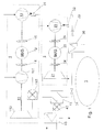
- FIG. 1 shows a first power plant according to the invention
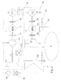
- Figure 2 shows a second embodiment of an inventive Power plant
- Figure 3 shows another example of an advantageous embodiment of a inventive power plant.
- a first embodiment of an inventive Power plant is shown in the figure 1.
- the power plant includes a first shaft train 1 and a second shaft train 2.
- On the first shaft train 1 is a gas turbine group 11 and a Compressor 13 is arranged.
- the gas turbo group and the compressor are arranged at the two ends of the shaft train.
- Between the Gas turbine group 11 and the compressor 13 is an electric machine 12 arranged, which are both electric motor and generator is operable.
- Switchable coupling elements 14 and 15 make it possible to the electric machine optionally with the gas turbine group 11 and the Compressor 13 to connect mechanically.
- the gas turbo group 11 is present as a simple, readily familiar to the skilled person Gas turbine group shown. It comprises a compressor 111, a Combustion chamber 112, and a turbine 113.
- a gas turbine group with sequential combustion such as it is known, for example, from EP 0 620 362.
- On the second Shaft strand 2 are at the two ends of the shaft strand one Relaxation machine 21 and a compressor 23 arranged. Between The relaxation machine and the compressor is one both generator as well as electric motor operable electric machine 22 arranged.
- By means of the coupling elements 24 and 25 is the electric machine optionally with the expansion machine 21 and the compressor 23 mechanically coupled.
- the compressors 13 and 23 are shown here as simple turbo compressors; without Limitation of the invention, the compressor can also have a Have intermediate cooling, or there may be several in series connected compressors with or without flow be arranged intermediate radiators on a shaft train.
- the gas turbo group on the One skilled in the art known in the present Embodiment not shown Translation or Reduction gear be arranged such that the speed of the Power or working machine of the speed of the electric machine is different. Especially in times of high energy demand is the Power plant operated in power mode. It is at least one of the coupling elements 14, 24 closed, the corresponding mechanical connection is thus made; the coupling elements 15th and 25 are open, so the corresponding mechanical connection is separated.
- the Gas turbine group 11 operated in a known per se.
- Heat recovery steam generator 43 arranged in the Flow path of the gas turbine group 11 is downstream of the turbine 113 for example, a person skilled in the art Heat recovery steam generator 43 arranged.
- the arrangement of the Heat recovery steam generator 43 is optional and not in itself relevant to the invention.
- In the heat recovery steam generator 43 is on to known manner by means of the exhaust gas in the gas turbine group contained residual energy generated steam, which in turn itself known manner for driving a steam turbine or other Process purposes can be used. It is also known to initiate the steam generated there in the gas turbine group and in the Gas turbo turbine working to relax.
- To drive the electric machine 22 is the expansion machine 21st operated.
- a stored in the storage volume 3 under pressure Storage fluid is via the actuator 34 to the expansion machine 21st guided and relaxed there doing work.
- the storage fluid flows through on the way from the storage volume 3 to the relaxation machine 21st a heat supply device and is heated.
- the Heat supply device is present as a heat exchanger 41 with a external firing device 42 shown.
- the benefits that come from this arrangement against an immediate firing of Storage fluids have been previously stated.
- the Heat exchanger 41 is also particularly well suited for use Low-temperature heat, such as solar heat or other low temperature heat, since the inflowing storage fluid is at low temperature, and in the Generally no high inlet temperature for the Relaxation machine 21 is required. On the contrary, it is beneficial to limit the temperature at the inlet of the expansion machine 21, for example, to a temperature of less than 500 ° C or less as 550 ° C.
- the compressors 13 and 23 have different rated power. For example, if one the compressors are twice as powerful as the other, so it is possible, the power consumption of the power plant in the ratio 1: 2: 3, the compressors each at the nominal operating point work. Downstream of the compressors are check members 31 and 32 arranged, which is a backflow of fluid through the compressors prevent. Preferably, the compressors 13 convey and compress and 23 ambient air stored under pressure in the storage volume 3 becomes. Downstream of the compressors 13, 23 and upstream of the Storage volume 3 is according to a preferred embodiment of Invention, a cooler 36 is arranged.
- the cooler 36 By means of the cooler 36, the during the largely adiabatic compression heated fluid be cooled down before it is supplied to the storage volume 3.
- For loading operation is at least one of the coupling elements 15 and 25th closed, and the coupling elements 14 and 24 are open.
- At least one of the electric machines 12 and 22 will operated by an electric motor and drives a compressor 13, 23, whereby the storage volume 3 is charged with storage fluid, which then back to work in the relaxation in the Relaxation machine 21 is available.
- FIG. 1 Another embodiment of the invention is shown in FIG.
- the power plant shown in Figure 1 also includes the power plant shown in Figure 2 two wave strands 1 and 2, on each of which an electric machine 12, 22, a compressor 13, 23 and a gas turbine group 11 and a storage fluid expansion machine 21 are arranged.
- the compressors 13 and 23rd fluidly not connected in parallel, but in series, such that from the compressor 13 compressed fluid flows to the compressor 23, and is further compressed by this.
- Downstream of the compressor 13 and upstream of the compressor 23 is a cooler 35 for the compressor 13 partially compressed fluid arranged.
- Downstream of the compressor 23 is a further cooler 36 arranged to cool the compressed fluid.
- an exhaust heat exchanger 44 is arranged. Of the Exhaust heat exchanger 44 is the primary side, on the heat-emitting Side, flows through the exhaust gas of the gas turbine group.
- the storage-fluid expansion machine 21 is storage fluid from the Storage volume 3 via the actuator 34 in countercurrent to the Exhaust gases of the gas turbine group passed through the exhaust gas heat exchanger 44; while the storage fluid absorbs heat from the exhaust gases, is thereby heated, and the heated storage fluid is working in the Storage fluid relaxation machine relaxes.
- the maximum achievable temperature of the storage fluid substantially corresponds to the Temperature of the exhaust gas exiting the turbine 113 of the Gas turbo group 11.
- the Compressors of the two wave strands are not independent of each other operate. That is, the operation of one of the compressors also requires the operation of the other compressor.
- the Compressors When operating the Compressors is the storage volume 3 with pressure storage fluid recharged, which afterwards again to the work-inducing relaxation in the storage fluid expansion machine 21 is available.
- the temperature of the exhaust gas is the Gas turbine group measured downstream of the heat exchanger 44, and for example, by regulating interventions on the actuator 34 of the Storage fluid mass flow adjusted such that the dew point of the Exhaust gas is not exceeded, or a safety margin for Dew point of the exhaust gases is maintained.
- a Additional firing device may be arranged to the storage fluid a to provide greater thermal performance.
- an additional firing 45 with a fan 46 outside the Flow path of the exhaust gas of the gas turbine group arranged. By the Operation of the fan 46 fresh air is directed to the additional firing 45, where a fuel can be burned.
- the resulting flue gases are passed through the exhaust heat exchanger 44, and also stand for heating the storage fluid in the exhaust gas heat exchanger 44 for Available.
- the external arrangement of the additional firing 45 with a Fresh air blower 46 has the advantage that the storage fluid expansion machine 21 also with heated storage fluid can be operated when the gas turbo group 11 is stopped. This increases the operational flexibility of the power plant considerably.
- Farther can also be an unillustrated exhaust gas bypass for the exhaust gas Gasturbo group be arranged, which allows the exhaust gas of the Gas turbine group on exhaust gas heat exchanger 44 pass. This has considerable advantages, if, for example, completely emptied Storage volume 3, the gas turbine group at standstill of the storage fluid expansion machine 21 is to be operated. It will then be the thermal load or overload on the secondary side not flowed through the exhaust heat exchanger 44 avoided.
- the invention shown in Figure 3 by way of example Power plant is in terms of thermal connection of the Gas turbine group 11 and the storage fluid expansion machine 21 constructed identically as the power plant shown in Figure 2.
- the arranged on the two shaft strands compressors 13 and 23rd are parallel to the flow as in the embodiment of FIG arranged, from which, as shown, a greater flexibility in operation the power plant results.
- a shut-off 37 arranged at the storage volume 3 at the here illustrated embodiment. This detail increases the operational flexibility as shown below considerably.
- the illustrated embodiment allows a Power operation of the power plant even with emptied Storage volume 3.
- the clutches 14 and Fig. 24 shows the connection of both the gas turbo group 11 and the Expansion machine 21 with the electric machines 12 and 22 ago.
- At least one of the clutches 15, 25 provides the connection of a electric machine with one of the compressors 13, 23 ago.
- the shut-off valve 37 is closed, the emptied or insufficient filled storage volume 3 is thus of the Power plant separated.
- the actuators 33 and 34 are open. From the compressors 13 and / or 23 funded compressed air is over the exhaust heat exchanger 44 is passed to the expansion machine 21 and working there relaxed. In the exhaust gas heat exchanger 44, the fluid heated thereby. This makes it possible for the expansion machine also at operate insufficient pressure in the storage volume. Furthermore, can the exhaust heat of the gas turbine group 11 advantageous even when emptied Storage volume can be used.
- the gas turbo group 11 can therefore also then be operated without problems, if no fluid from the Storage volume 3 is available, and no bypass line for the Exhaust heat exchanger 44 is arranged.
- the cooler 36 is in this Operating mode with advantage out of service.
- the exemplary embodiments illustrated on the one hand illustrate the one hand high operational flexibility of the power plant according to the invention. Furthermore, it becomes clear that the utilization of the used Resources is far better than those of the prior art known power plants. In particular, each of the electrical Machines both in power operation and in the loading operation of the Power plant operated. The gas turbine group makes it possible also to produce power when the storage volume 3 is completely emptied. In the light of these remarks open up to the The skilled person readily further possible embodiments of the Invention. Further potential for savings and improvement can be opened up This is because the electrical machines working on the two Wave strands are arranged, a common electrical Equipment can use.
- step-up transformer For the power plant with two wave strands, for example, only one grid connection transformer, so-called “step-up transformer", and a starting device, For example, a static frequency converter required.
- step-up transformer For example, a static frequency converter required.
Landscapes
- Engineering & Computer Science (AREA)
- Chemical & Material Sciences (AREA)
- Combustion & Propulsion (AREA)
- Mechanical Engineering (AREA)
- General Engineering & Computer Science (AREA)
- Structures Of Non-Positive Displacement Pumps (AREA)
- Engine Equipment That Uses Special Cycles (AREA)
Abstract
Description
Claims (10)
- Luftspeicherkraftwerksanlage, mit einem Kompressor-Leistungsaufnahmefähigkeit und einer Generationsleistungsfähigkeit, wobei die Generationsleistungsfähigkeit von einer Gasturbogruppe (11) und einer Entspannungsmaschine (21) für ein Druckspeicherfluid zur Verfügung gestellt wird, wobei die Gasturbogruppe (11) mit einer ersten elektrischen Maschine (12) auf einem ersten Wellenstrang (1) angeordnet ist und die Entspannungsmaschine (21) mit einer zweiten elektrischen Maschine (22) auf einem zweiten Wellenstrang (2) angeordnet ist, dadurch gekennzeichnet, dass die Kompressor-Leistungsaufnahmefähigkeit auf einen ersten Kompressor (13) und einen zweiten Kompressor (13) aufgeteilt ist und der erste Kompressor auf dem ersten Wellenstrang und der zweite Kompressor auf dem zweiten Wellenstrang angeordnet ist.
- Kraftwerksanlage gemäss Anspruch 1, dadurch gekennzeichnet, dass die Gasturbogruppe (11) einen Abgaswärmetauscher (44) aufweist, wobei der Abgaswärmetauscher primärseitig vom entspannten Heissgas der Gasturbogruppe durchströmbar ist und sekundärseitig von dem der Entspanungsmaschine (21) zuströmenden Speicherfluid durchströmbar ist.
- Kraftwerksanlage gemäss einem der vorstehenden Ansprüche, dadurch gekennzeichnet, dass der erste Kompressor (13) und der zweite Kompressor (23) strömungsmässig parallel geschaltet sind, derart, dass insbesondere jeder Kompressor Umgebungsluft ansaugt und beide Kompressoren in ein gemeinsames Speichervolumen (3) fördern.
- Kraftwerksanlage gemäss einem der Ansprüche 1 oder 2, dadurch gekennzeichnet, dass die Kompressoren strömungsmässig in Reihe geschaltet sind, derart, dass insbesondere ein Kompressor (13) Luft aus der Umgebung ansaugt, die verdichtete Luft zu dem anderen Kompressor (23) leitet, und dieser die weiterverdichtete Luft in ein Speichervolumen (3) fördert.
- Kraftwerksanlage gemäss Anspruch 4, dadurch gekennzeichnet, dass zwischen den Kompressoren (13, 23) ein Kühler (35) für das teilverdichtete Fluid angeordnet ist.
- Kraftwerksanlage gemäss einem der vorstehenden Ansprüche, dadurch gekennzeichnet, dass eine Wärmezuführeinrichtung (41,42) für der Entspannungsmaschine (21) zuströmendes Speicherfluid angeordnet ist.
- Kraftwerksanlage gemäss einem der vorstehenden Ansprüchen,dadurch gekennzeichnet, dass beide elektrischen Maschinen sowohl elektromotorisch als auch generatorisch betreibbar sind.
- Kraftwerksanlage gemäss einem der vorstehenden Ansprüche, dadurch gekennzeichnet, dass die maximale Leistungsabgabe der Gasturbogruppe grösser als oder wenigstens gleich gross ist wie die maximale Leistungsaufnahme des ersten Kompressors, und, dass die maximale Leistungsabgabe der Entspannungsmaschine grösser als oder wenigstens gleich gross ist wie die maximale Leistungsaufnahme des zweiten Kompressors.
- Kraftwerksanlage gemäss einem der vorstehenden Ansprüche, dadurch gekennzeichnet, dass das maximale Druckverhältnis der Kompression grösser als 50 und insbesondere grösser als 100 ist.
- Kraftwerksanlage gemäss einem der vorstehenden Ansprüche, dadurch gekennzeichnet, dass die gesamte Verdichterleistung des ersten und des zweiten Kompressors zusammen grösser als 100 MW, insbesondere grösser als 120 MW, ist.
Applications Claiming Priority (2)
| Application Number | Priority Date | Filing Date | Title |
|---|---|---|---|
| DE102004007482 | 2004-02-13 | ||
| DE102004007482A DE102004007482B4 (de) | 2004-02-13 | 2004-02-13 | Kraftwerksanlage |
Publications (2)
| Publication Number | Publication Date |
|---|---|
| EP1564391A2 true EP1564391A2 (de) | 2005-08-17 |
| EP1564391A3 EP1564391A3 (de) | 2013-05-15 |
Family
ID=34684075
Family Applications (1)
| Application Number | Title | Priority Date | Filing Date |
|---|---|---|---|
| EP05100718.5A Withdrawn EP1564391A3 (de) | 2004-02-13 | 2005-02-02 | Kraftwerksanlage |
Country Status (4)
| Country | Link |
|---|---|
| US (1) | US7150154B2 (de) |
| EP (1) | EP1564391A3 (de) |
| CA (1) | CA2496355C (de) |
| DE (1) | DE102004007482B4 (de) |
Cited By (2)
| Publication number | Priority date | Publication date | Assignee | Title |
|---|---|---|---|---|
| WO2007023094A1 (de) | 2005-08-23 | 2007-03-01 | Alstom Technology Ltd | Kraftwerksanlage |
| EP2378100A3 (de) * | 2009-10-27 | 2014-07-02 | General Electric Company | System und Verfahren zur Verwendung eines Druckluftspeichersystems mit einer Gasturbine |
Families Citing this family (34)
| Publication number | Priority date | Publication date | Assignee | Title |
|---|---|---|---|---|
| DE102004028531A1 (de) * | 2004-06-11 | 2006-01-05 | Alstom Technology Ltd | Verfahren zum Betrieb einer Kraftwerksanlage, und Kraftwerksanlage |
| US20060117752A1 (en) * | 2004-12-07 | 2006-06-08 | Zabtcioglu Fikret M | Hydraulic-compression power central heating system and method |
| US20060201148A1 (en) * | 2004-12-07 | 2006-09-14 | Zabtcioglu Fikret M | Hydraulic-compression power cogeneration system and method |
| US20070256424A1 (en) * | 2006-05-05 | 2007-11-08 | Siemens Power Generation, Inc. | Heat recovery gas turbine in combined brayton cycle power generation |
| US7614237B2 (en) * | 2007-01-25 | 2009-11-10 | Michael Nakhamkin | CAES system with synchronous reserve power requirements |
| US8261552B2 (en) * | 2007-01-25 | 2012-09-11 | Dresser Rand Company | Advanced adiabatic compressed air energy storage system |
| US8011189B2 (en) * | 2007-01-25 | 2011-09-06 | Michael Nakhamkin | Retrofit of simple cycle gas turbine for compressed air energy storage application having expander for additional power generation |
| JP4196307B1 (ja) * | 2008-03-06 | 2008-12-17 | 三浦工業株式会社 | 蒸気システム |
| US8196395B2 (en) | 2009-06-29 | 2012-06-12 | Lightsail Energy, Inc. | Compressed air energy storage system utilizing two-phase flow to facilitate heat exchange |
| US8436489B2 (en) | 2009-06-29 | 2013-05-07 | Lightsail Energy, Inc. | Compressed air energy storage system utilizing two-phase flow to facilitate heat exchange |
| US8247915B2 (en) | 2010-03-24 | 2012-08-21 | Lightsail Energy, Inc. | Energy storage system utilizing compressed gas |
| US8146354B2 (en) | 2009-06-29 | 2012-04-03 | Lightsail Energy, Inc. | Compressed air energy storage system utilizing two-phase flow to facilitate heat exchange |
| GB2476489B (en) * | 2009-12-23 | 2012-02-15 | Global Power And Energy Ltd | Compressed Air Energy Storage Systems |
| US8978380B2 (en) | 2010-08-10 | 2015-03-17 | Dresser-Rand Company | Adiabatic compressed air energy storage process |
| EP2715075A2 (de) * | 2011-05-17 | 2014-04-09 | Sustainx, Inc. | Systeme und verfahren für effizienten zweiphasigen wärmetransfer in druckluftenergiespeichersystemen |
| KR101204908B1 (ko) * | 2011-06-30 | 2012-11-26 | 삼성테크윈 주식회사 | 압축 가스를 이용한 동력 생산 시스템 |
| WO2013116185A1 (en) * | 2012-01-30 | 2013-08-08 | Kraft Robert J | Gas turbine energy storage and energy supplementing systems and methods of making and using the same |
| WO2013151909A1 (en) * | 2012-04-02 | 2013-10-10 | Kraft Robert J | Compressed air injection system method and apparatus for gas turbine engines |
| US9890707B2 (en) * | 2012-04-02 | 2018-02-13 | Powerphase Llc | Gas turbine efficiency and regulation speed improvements using supplementary air system continuous and storage systems and methods of using the same |
| WO2014055717A1 (en) | 2012-10-04 | 2014-04-10 | Kraft Robert J | Aero boost - gas turbine energy supplementing systems and efficient inlet cooling and heating, and methods of making and using the same |
| US9003763B2 (en) * | 2012-10-04 | 2015-04-14 | Lightsail Energy, Inc. | Compressed air energy system integrated with gas turbine |
| US8726629B2 (en) | 2012-10-04 | 2014-05-20 | Lightsail Energy, Inc. | Compressed air energy system integrated with gas turbine |
| KR102009583B1 (ko) | 2012-10-26 | 2019-08-09 | 파워페이즈 엘엘씨 | 가스 터빈 에너지 보조 시스템 및 가열 시스템, 그리고 그 제작 및 이용 방법 |
| US9938895B2 (en) | 2012-11-20 | 2018-04-10 | Dresser-Rand Company | Dual reheat topping cycle for improved energy efficiency for compressed air energy storage plants with high air storage pressure |
| US20140175803A1 (en) * | 2012-12-26 | 2014-06-26 | General Electric Company | Biomass conversion reactor power generation system and method |
| ITFI20130299A1 (it) * | 2013-12-16 | 2015-06-17 | Nuovo Pignone Srl | "improvements in compressed-air-energy-storage (caes) systems and methods" |
| US20150176489A1 (en) * | 2013-12-20 | 2015-06-25 | Boge Kompressoren Otto Boge Gmbh & Co. Kg | Unknown |
| JP6614878B2 (ja) * | 2014-12-25 | 2019-12-04 | 株式会社神戸製鋼所 | 圧縮空気貯蔵発電装置及び圧縮空気貯蔵発電方法 |
| CN107917074B (zh) * | 2017-11-09 | 2020-06-09 | 华北电力大学 | 一种给恒压储气源供气的专用空压机系统 |
| US10570783B2 (en) * | 2017-11-28 | 2020-02-25 | Hanwha Power Systems Co., Ltd | Power generation system using supercritical carbon dioxide |
| JP6796577B2 (ja) * | 2017-12-28 | 2020-12-09 | 株式会社神戸製鋼所 | 圧縮空気貯蔵発電装置および圧縮空気貯蔵発電方法 |
| CN110630467B (zh) * | 2019-09-19 | 2020-12-15 | 东北大学 | 一种可提高电-电转换效率的压缩空气储能系统及方法 |
| US11708791B1 (en) * | 2020-12-02 | 2023-07-25 | Bright Generation Holdings, LLC | System and method for compressed air energy storage with wide temperature range thermal storage |
| CN112648076B (zh) * | 2020-12-22 | 2022-03-01 | 东北大学 | 一种压缩空气储能系统 |
Family Cites Families (12)
| Publication number | Priority date | Publication date | Assignee | Title |
|---|---|---|---|---|
| FR2224642A1 (en) * | 1973-04-03 | 1974-10-31 | Electricite De France | Gas turbine power station operation system - decompresses air from receiver in motor driving auxiliary compressor |
| GB1583648A (en) * | 1976-10-04 | 1981-01-28 | Acres Consulting Services | Compressed air power storage systems |
| US4441028A (en) * | 1977-06-16 | 1984-04-03 | Lundberg Robert M | Apparatus and method for multiplying the output of a generating unit |
| US4872307A (en) * | 1987-05-13 | 1989-10-10 | Gibbs & Hill, Inc. | Retrofit of simple cycle gas turbines for compressed air energy storage application |
| US5685155A (en) * | 1993-12-09 | 1997-11-11 | Brown; Charles V. | Method for energy conversion |
| IL108546A (en) * | 1994-02-03 | 1997-01-10 | Israel Electric Corp Ltd | Compressed air energy storage method and system |
| US5778675A (en) * | 1997-06-20 | 1998-07-14 | Electric Power Research Institute, Inc. | Method of power generation and load management with hybrid mode of operation of a combustion turbine derivative power plant |
| US6038849A (en) * | 1998-07-07 | 2000-03-21 | Michael Nakhamkin | Method of operating a combustion turbine power plant using supplemental compressed air |
| US5934063A (en) * | 1998-07-07 | 1999-08-10 | Nakhamkin; Michael | Method of operating a combustion turbine power plant having compressed air storage |
| DE10236326A1 (de) * | 2001-08-17 | 2003-03-06 | Alstom Switzerland Ltd | Gasspeicherkraftanlage |
| US6745569B2 (en) * | 2002-01-11 | 2004-06-08 | Alstom Technology Ltd | Power generation plant with compressed air energy system |
| DE102004040890A1 (de) * | 2003-09-04 | 2005-03-31 | Alstom Technology Ltd | Kraftwerksanlage, und Verfahren zum Betrieb |
-
2004
- 2004-02-13 DE DE102004007482A patent/DE102004007482B4/de not_active Expired - Fee Related
- 2004-04-08 US US10/819,924 patent/US7150154B2/en not_active Expired - Fee Related
-
2005
- 2005-02-02 EP EP05100718.5A patent/EP1564391A3/de not_active Withdrawn
- 2005-02-04 CA CA2496355A patent/CA2496355C/en not_active Expired - Fee Related
Non-Patent Citations (1)
| Title |
|---|
| None * |
Cited By (3)
| Publication number | Priority date | Publication date | Assignee | Title |
|---|---|---|---|---|
| WO2007023094A1 (de) | 2005-08-23 | 2007-03-01 | Alstom Technology Ltd | Kraftwerksanlage |
| US7692327B2 (en) | 2005-08-23 | 2010-04-06 | Alstom Technology Ltd | Power generating plant |
| EP2378100A3 (de) * | 2009-10-27 | 2014-07-02 | General Electric Company | System und Verfahren zur Verwendung eines Druckluftspeichersystems mit einer Gasturbine |
Also Published As
| Publication number | Publication date |
|---|---|
| US20050178114A1 (en) | 2005-08-18 |
| DE102004007482A1 (de) | 2005-09-15 |
| CA2496355C (en) | 2013-08-20 |
| EP1564391A3 (de) | 2013-05-15 |
| DE102004007482B4 (de) | 2010-06-24 |
| CA2496355A1 (en) | 2005-08-13 |
| US7150154B2 (en) | 2006-12-19 |
Similar Documents
| Publication | Publication Date | Title |
|---|---|---|
| DE102004007482B4 (de) | Kraftwerksanlage | |
| EP1917428B1 (de) | Verfahren zum betrieb einer kraftwerksanlage mit einem druckspeicher | |
| EP1483490A1 (de) | Krafterzeugungsanlage | |
| DE4213023A1 (de) | Verfahren zum Betrieb eines Gasturbogruppe | |
| EP2574739A1 (de) | Anlage zur Speicherung thermischer Energie und Verfahren zu deren Betrieb | |
| EP2808500A1 (de) | Wärmepumpe mit einer in einem Kreislauf geschalteten ersten thermischen Fluidenergie-Maschine und zweiten thermischen Fluidenergie-Maschine | |
| EP1512855A1 (de) | Kraftwerksanlage, und Verfahren zum Betrieb | |
| DE4210541A1 (de) | Verfahren zum Betrieb einer Gasturbogruppe | |
| AT12639U1 (de) | Elektrisches Kraftwerk | |
| DD141049A5 (de) | Gasturbinenanlage | |
| EP1795725A1 (de) | Gasturbine mit Kühlluftkühlung | |
| EP2876280B1 (de) | Mikrogasturbinenanordnung | |
| CH229280A (de) | Gasturbinen-Anlage. | |
| DE1564655C3 (de) | Kernkraftwerk mit CO tief 2-Kühlung | |
| EP2574738A1 (de) | Anlage zur Speicherung thermischer Energie | |
| DE102004040890A1 (de) | Kraftwerksanlage, und Verfahren zum Betrieb | |
| DE202005003611U1 (de) | Wärmekraftwerk mit Druckluftspeichervorrichtung zum Ausgleich fluktuierender Energieeinspeisung aus regenerativen Energiequellen | |
| AT510011B1 (de) | Kraftwerksblock | |
| DE2102770A1 (de) | Anlage einer Gasturbine mit Energiespeicherung gebunden mit einer Dampfturbine | |
| DE102004034657A1 (de) | Kraftwerksanlage | |
| DE102004040577A1 (de) | Verfahren zum Anfahren einer Kraftwerksanlage in einem stromlosen Elektrizitätsnetz, und Kraftwerksanlage | |
| CH696980A5 (de) | Verfahren zum Anfahren einer Kraftwerksanlage in einem Elektrizitätsnetz, und Kraftwerksanlage. | |
| DE1539904B1 (de) | Kernenergie-Waermekraftanlage | |
| DE102005060831B4 (de) | Geschlossener Gasturbinenprozess | |
| EP1536118A1 (de) | Kraftwerksanlage |
Legal Events
| Date | Code | Title | Description |
|---|---|---|---|
| PUAI | Public reference made under article 153(3) epc to a published international application that has entered the european phase |
Free format text: ORIGINAL CODE: 0009012 |
|
| AK | Designated contracting states |
Kind code of ref document: A2 Designated state(s): AT BE BG CH CY CZ DE DK EE ES FI FR GB GR HU IE IS IT LI LT LU MC NL PL PT RO SE SI SK TR |
|
| AX | Request for extension of the european patent |
Extension state: AL BA HR LV MK YU |
|
| PUAL | Search report despatched |
Free format text: ORIGINAL CODE: 0009013 |
|
| AK | Designated contracting states |
Kind code of ref document: A3 Designated state(s): AT BE BG CH CY CZ DE DK EE ES FI FR GB GR HU IE IS IT LI LT LU MC NL PL PT RO SE SI SK TR |
|
| AX | Request for extension of the european patent |
Extension state: AL BA HR LV MK YU |
|
| RIC1 | Information provided on ipc code assigned before grant |
Ipc: F02C 6/16 20060101AFI20130405BHEP |
|
| 17P | Request for examination filed |
Effective date: 20130830 |
|
| RBV | Designated contracting states (corrected) |
Designated state(s): AT BE BG CH CY CZ DE DK EE ES FI FR GB GR HU IE IS IT LI LT LU MC NL PL PT RO SE SI SK TR |
|
| AKX | Designation fees paid |
Designated state(s): AT BE BG CH CY CZ DE DK EE ES FI FR GB GR HU IE IS IT LI LT LU MC NL PL PT RO SE SI SK TR |
|
| 17Q | First examination report despatched |
Effective date: 20150714 |
|
| RAP1 | Party data changed (applicant data changed or rights of an application transferred) |
Owner name: GENERAL ELECTRIC TECHNOLOGY GMBH |
|
| STAA | Information on the status of an ep patent application or granted ep patent |
Free format text: STATUS: THE APPLICATION IS DEEMED TO BE WITHDRAWN |
|
| 18D | Application deemed to be withdrawn |
Effective date: 20170811 |