EP1564061B1 - Gas pedal - Google Patents
Gas pedal Download PDFInfo
- Publication number
- EP1564061B1 EP1564061B1 EP03797530A EP03797530A EP1564061B1 EP 1564061 B1 EP1564061 B1 EP 1564061B1 EP 03797530 A EP03797530 A EP 03797530A EP 03797530 A EP03797530 A EP 03797530A EP 1564061 B1 EP1564061 B1 EP 1564061B1
- Authority
- EP
- European Patent Office
- Prior art keywords
- nails
- pad
- pad member
- stopper
- accelerator pedal
- Prior art date
- Legal status (The legal status is an assumption and is not a legal conclusion. Google has not performed a legal analysis and makes no representation as to the accuracy of the status listed.)
- Expired - Lifetime
Links
Images



Classifications
-
- G—PHYSICS
- G05—CONTROLLING; REGULATING
- G05G—CONTROL DEVICES OR SYSTEMS INSOFAR AS CHARACTERISED BY MECHANICAL FEATURES ONLY
- G05G1/00—Controlling members, e.g. knobs or handles; Assemblies or arrangements thereof; Indicating position of controlling members
- G05G1/30—Controlling members actuated by foot
- G05G1/50—Manufacturing of pedals; Pedals characterised by the material used
- G05G1/506—Controlling members for foot-actuation
-
- B—PERFORMING OPERATIONS; TRANSPORTING
- B60—VEHICLES IN GENERAL
- B60K—ARRANGEMENT OR MOUNTING OF PROPULSION UNITS OR OF TRANSMISSIONS IN VEHICLES; ARRANGEMENT OR MOUNTING OF PLURAL DIVERSE PRIME-MOVERS IN VEHICLES; AUXILIARY DRIVES FOR VEHICLES; INSTRUMENTATION OR DASHBOARDS FOR VEHICLES; ARRANGEMENTS IN CONNECTION WITH COOLING, AIR INTAKE, GAS EXHAUST OR FUEL SUPPLY OF PROPULSION UNITS IN VEHICLES
- B60K26/00—Arrangement or mounting of propulsion-unit control devices in vehicles
- B60K26/02—Arrangement or mounting of propulsion-unit control devices in vehicles of initiating means or elements
-
- G—PHYSICS
- G05—CONTROLLING; REGULATING
- G05G—CONTROL DEVICES OR SYSTEMS INSOFAR AS CHARACTERISED BY MECHANICAL FEATURES ONLY
- G05G1/00—Controlling members, e.g. knobs or handles; Assemblies or arrangements thereof; Indicating position of controlling members
- G05G1/30—Controlling members actuated by foot
-
- G—PHYSICS
- G05—CONTROLLING; REGULATING
- G05G—CONTROL DEVICES OR SYSTEMS INSOFAR AS CHARACTERISED BY MECHANICAL FEATURES ONLY
- G05G1/00—Controlling members, e.g. knobs or handles; Assemblies or arrangements thereof; Indicating position of controlling members
- G05G1/30—Controlling members actuated by foot
- G05G1/44—Controlling members actuated by foot pivoting
-
- Y—GENERAL TAGGING OF NEW TECHNOLOGICAL DEVELOPMENTS; GENERAL TAGGING OF CROSS-SECTIONAL TECHNOLOGIES SPANNING OVER SEVERAL SECTIONS OF THE IPC; TECHNICAL SUBJECTS COVERED BY FORMER USPC CROSS-REFERENCE ART COLLECTIONS [XRACs] AND DIGESTS
- Y10—TECHNICAL SUBJECTS COVERED BY FORMER USPC
- Y10T—TECHNICAL SUBJECTS COVERED BY FORMER US CLASSIFICATION
- Y10T74/00—Machine element or mechanism
- Y10T74/20—Control lever and linkage systems
- Y10T74/20528—Foot operated
- Y10T74/20534—Accelerator
Definitions
- the present invention relates to an accelerator pedal for a vehicle, and particularly relates to an accelerator pedal, in which a pad member is integrally molded by resin and has a fit-in structure for a stopper member.
- the accelerator pedal is fixed by bolts, etc. on a floor carpet that is laid entirely over the floor of the driver's seat.
- the floor carpet is washed, repaired or replaced with another one, it is necessary to disassemble a pad member, an arm and a bracket of the accelerator pedal, and then detach the stopper member fixed on the floor of the driver's seat.
- the stopper member is fixed on the floor by bolts, and then the pad member is fitted into the stopper member. And the arm and the bracket are engaged with the pad member, and thereafter the throttle for controlling the engine speed is readjusted.
- a fasteningmethod for example, employing a snap-fit structure, in which fastening is made use of the flexibility of the resin, is conventionally known.
- a fasteningmethod for example, employing a snap-fit structure, in which fastening is made use of the flexibility of the resin.
- the resinous nails are made of a resin having a higher hardness instead of a soft resin ranging from resin to rubber.
- Japanese Laid-open Patent Application No. 2001-270343 (Pages 3-4, and FIG. 2 ) discloses such an accelerator pedal structure for vehicles, which includes a restricting member for restricting a relative movement between the accelerator pedal pad and the retainer in the rotation shaft direction, so as to minimize the backlash amount in the rotation shaft direction.
- the fit-in structure where the fastening member is deflected and fitted into the corresponding fastened member upon engagement thereof prevents removal and backlash of the fastening member.
- the resinous nails of the fastening member are not of a deformation proof structure, for example, with respect to the deformation of the resin, therefore, it may cause a deformation and thereby causing removal of the nails regardless of whether or not the fastened member deforms.
- the accelerator pedal is fixed by bolts on the floor carpet that is laid entirely over the floor of the driver' s seat.
- the floor carpet is washed, repaired or replaced with another one, it is necessary to detach the stopper member that is fixed on the floor of the driver's seat.
- the pad member, the arm, and the bracket have to be disassembled.
- there is a drawback such that the pad member is difficult to be detached from the stopper member.
- GB-A-1 156 599 discloses an accelerator pedal comprising a stopper member attached to a floor of a driver's seat of the vehicle; a pad member to be fitted against the stopper member and having a pad for receiving a depression force exerted by a driver; an arm which is engaged with the pad member and transmits the depression force; a bracket which is engaged with the arm and supports the arm; a stopper fitting section provided on the pad member and including nails to be fitted into the stopper member and supporting plates connecting the pad member and the nails, nail catch sections provided in the stopper member and against which the nails are hooked; and a hinge section provided for connecting the pad member and the stopper fitting section; whereby the pad member is made from resin, the nails are inserted toward the nail catch sections with the supporting plates bent inwardly from an initial state, and the nails are hooked against the nail catch sections after the insertion with the supporting plates returned to the initial state.
- JP 05016449 U discloses an arrangement in which engaging nails are fitted to engaged portions by a lower portion and the invention also discloses an arrangement in which the nails are fitted to the nail catch sections, wherein the lower portion is for expanding engaging members so that the engaging nails are engaged to the engaged portions. Further, in JP 05016449 U , since the engaging members are fitted in bent state, a clearance will be formed between the engaging members and the engaged portions due to the bending of the engaging members, therefore backlash will be caused.
- US-A-5 761 967 shows an accelerator pedal comprising:
- the present invention is proposed to solve the above drawbacks, and the purpose of the present invention is to readily detach the pad member from the stopper member without causing removal and backlash of the pad member relative to the stopper member.
- an accelerator pedal includes: a stopper member attached to a floor of a drivers seat of the vehicle; a pad member to be fitted against the stopper member and having a pad for receiving a depression force exerted by a driver; an arm which is engaged with the pad member and transmits the depression force; a bracket which is engaged with the arm and supports the arm; a stopper fitting section provided on the pad member and including nails to be fitted into the stopper member and supporting plates connecting the pad member and the nails, nail catch sections provided in the stopper member and against which the nails are hooked; and a hinge section provided for connecting the pad member and the stopper fitting section; characterized in that the pad member is made from resin, the nails are inserted toward the nail catch sections with the supporting plates bent inwardly from an initial state, and the nails are hooked against the nail catch sections after the insertion with the supporting plates returned to the initial state, and a backup plate is provided which prevents the supporting plates from being deformed from the initial state, so that the backup plate urge
- the pad member since the pad member is made of resin, the pad member can be deflected and fitted due to softness of the resin material. After fastening the pad member, it returns to the original shape, thereby preventing the removal and backlash of the pad member.
- the pad, the hinge section, and the stopper fitting section are integrally molded by a single resin material.
- the pad member is integrally molded by a single resin material, it is possible to omit an attachment section in the pad member, thereby preventing the removal and backlash of the pad member.
- the pad, the hinge section, and the stopper fitting section are made of soft polyester elastomer.
- the pad member is made of a soft resin, the pad member can be readily detached from the stopper member by twisting the pad member with hand. Therefore, the floor carpet can be removed with ease, resulting in a decrease of the labor involving washing, repairing or replacement of the floor carpet.
- FIG. 1 is a perspective view schematically illustrating a driver's seat where an accelerator pedal according to one embodiment of the present invention is provided at its foot.
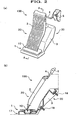
- the accelerator pedal 100 includes a pad member 20 to be operated by the depression force of the driver, a stopper member 30 to be mounted on a floor carpet that is laid over the floor of the vehicle, an arm 4 for transmitting the depression force exerted on the pad member 20, and a bracket 5 for supporting the arm 4.
- the pad member 20 and the stopper member 30 are made of a soft resin which can be readily deformed by hand.
- the pad member 20 consisting of a pad 2, a hinge section 10, and a stopper fitting section 1 is integrally molded by polyester elastomer (PE), and the stopper 30 is integrally molded by a resin which is synthesized by polypropylene (PP) and talc.
- PE polyester elastomer
- PP polypropylene
- the stopper member 30 is fixed to the floor surface of the vehicle over the floor carpet (not shown) by bolts 18, 18 from the interior side of the cabin. Attached to the lower end of the stopper member 30 is the lower end of the pad member 20.
- One end of the arm 4 is engaged with the upper end of the pad member 20, and the other end of the arm 4 is engaged with the bracket 5.
- the bracket 5 is engaged with the arm 4 and fixed to the vehicle body by bolts, such that the pad 2 is retained in the non-depressed position by the spring force of the spring (not shown) provided at the bracket 5.
- the depression force is transmitted to the arm 4 and moves the throttle (not shown) connected to the arm 4, thereby controlling the rotational speed of the engine (not shown).
- the stopper 3 defines a lower limit for the depression of the pad 2.
- the reference numeral 10 denotes a hinge section which joins the pad 2 and the stopper fitting section 1, and the hinge section 10 is molded integrally with the pad 2 and the stopper fitting section 1.
- the stopper member 30 is provided with the insertion hole 13 for the nails. Inserted into this insertion hole 13 are the nails 6a, 6b of the pad member 20 and supporting plates 11a, 11b for the nails, so that the fastening of the pad member 20 and the stopper member 30 can be accomplished. Further, the stopper member 30 is provided with a second release hole 9 which allows a thin rod to be inserted through for depressing the backup plate 7 to be described later.
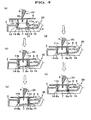
- FIG. 4 shows a state where the nails 6a, 6b at the lower end of the pad member 20, together with the supporting plates 11a, 11b, are inserted halfway through the receiving surfaces 12 for the nails of the stopper member 30.
- the nails 6a, 6b are inserted together with the supporting plates 11a, 11b, while being bent inwardly.
- the nails 6a, 6b are facing each other in such a manner to be bent inwardly by the pressing force received from the inner surfaces of the receiving surfaces 12, 12.
- FIG. 4(b) shows a state where the nails 6a, 6b and the supporting plates 11a, 11b for the nails are advanced farther into the insertion hole 13 of the stopper member 30.
- one nail 6a abuts on the backup plate 7 and depresses the backup plate 7. Since the backup plate 7 is integral with the stopper member 30 and is made of a soft resin, a man can easily deform the backup plate 7.
- FIG. 4(c) shows a state where the nails 6a, 6b and the supporting plates 11a, 11b for the nails are advanced farther into the insertion hole 13 of the stopper member 30.
- one nail 6a abuts on the backup plate 7 and depresses the backup plate 7 farther, and the other nail 6b is hooked through the nail catch section 14.
- the nail 6a is not yet hooked through the nail catch section 14.
- FIG. 4(d) shows a state where the nails 6a, 6b and the supporting plates 11a, 11b for the nails are advanced farther to the downward direction.
- the nail 6b is hooked through the nail catch section 14, while the nail 6a enters a nail relief hole 15 provided in the backup plate 7 and is slightly hooked through the nail catch section 14.
- FIG. 4(e) shows a state where the nails 6a, 6b and the supporting plates 11a, 11b for the nails are advanced farther to the downward direction.
- the nails 6a, 6b are both hooked through the nail catch sections 14, 14.
- the backup plate 7 is released from the press-down force of the nails, and moves upward to return to the original position.
- the nails 6a, 6b of the pad member 20 are both hooked through the nail catch sections 14, 14, and the backup plate 7 urges the nails 6a, 6b upward to secure the reliable engagement between the nails 6a, 6b and the nail catch sections 14, 14, thereby preventing removal and backlash of the nails 6a, 6b.
- the nails 6a, 6b are inserted through the insertion hole 13 with the supporting plates 11a, 11b for the nails bent inwardly, and return to their original position after passing through the receiving surfaces 12 for the nails, to thereby accomplish the fitting engagement between the pad member 20 and the stopper member 30. Since the nails 6a, 6b are easily deformed, the fitting operation can be readily carried out.
- the pad member 20 is fitted into the stopper member 30, and when the driver depresses the pad 2 of the accelerator pedal 100, the pad 2 arcuately turns upward and downward around the hinge section 10 as a fulcrum. Therefore, the arm 4 engaged with the upper end of the pad 2 is pressed and pulls the throttle (not shown) to control the rotation speed of the engine (not shown).
- FIG. 5 shows sections of a series of operations for detaching the pad member 20 from the stopper member 30.
- FIG. 5(a) shows a state where the nails 6a, 6b and the supporting plates 11a, 11b for the nails are depressed and the nails 6a, 6b are hooked through the nail catch sections 14, 14.
- the backup plate 7 positions upward. Therefore, the backup plate 7 urges the nails 6a, 6b upward so as to prevent the nails 6a, 6b from being pulled out from the nail catch sections 14, 14.
- FIG. 5(b) shows a state where a thin long rod 16 such as a pencil is inserted into the first release hole 8 of the pad member 20 and the second release hole 9 of the stopper member 30 in order to detach the pad member 20 from the stopper member 30, so that the release point P of the backup plate 7 is depressed.
- a thin long rod 16 such as a pencil
- FIG. 5(c) shows a state where one hand, for example, a right hand grips the pad 2 and turns it in the horizontal direction as shown by the arrow, while the other hand, for example, a left hand keeps on depressing the backup plate 7.
- the supporting plates 11a, 11b of the pad member 20 are slightly deformed inward as shown by the arrows.
- FIG. 5 (d) shows a state where the pad 2 is rotated farther in the horizontal direction, so that the nails 6a, 6b are disengaged from the nail catch sections 14, 14.
- FIG. 5(e) shows a state where the left hand holding the pad 2 is raised in the vertical direction, while retaining the condition illustrated in (d), so as to disengage the pad member 20 from the stopper member 30.
- the left hand holding the thin rod 16 such as a pencil also releases the depressing force.
- the pad member 20 can be readily detached from the stopper member 30 by pulling out the pad 2 in the vertical direction.
- the floor carpet upon removing the floor carpet that is laid on the floor of the driver' s seat, it is not necessary to disassemble the arm 4 and the bracket 5. Therefore, the floor carpet can be removed without touching the throttle for controlling the engine speed, which can decrease the number of operations required.
- the pad member is made of polyester elastomer (PE) in the preferred embodiment, other known resin materials may be used as long as it is a resin having flexibility.
- PE polyester elastomer
Landscapes
- Engineering & Computer Science (AREA)
- Physics & Mathematics (AREA)
- General Physics & Mathematics (AREA)
- Automation & Control Theory (AREA)
- Chemical & Material Sciences (AREA)
- Combustion & Propulsion (AREA)
- Transportation (AREA)
- Mechanical Engineering (AREA)
- Manufacturing & Machinery (AREA)
- Auxiliary Drives, Propulsion Controls, And Safety Devices (AREA)
- Mechanical Control Devices (AREA)
- Control Of Throttle Valves Provided In The Intake System Or In The Exhaust System (AREA)
Abstract
Description
- The present invention relates to an accelerator pedal for a vehicle, and particularly relates to an accelerator pedal, in which a pad member is integrally molded by resin and has a fit-in structure for a stopper member.
- Conventionally, the accelerator pedal is fixed by bolts, etc. on a floor carpet that is laid entirely over the floor of the driver's seat. In the case where the floor carpet is washed, repaired or replaced with another one, it is necessary to disassemble a pad member, an arm and a bracket of the accelerator pedal, and then detach the stopper member fixed on the floor of the driver's seat.
- After the floor carpet is removed and washed, repaired or replaced with another one, the stopper member is fixed on the floor by bolts, and then the pad member is fitted into the stopper member. And the arm and the bracket are engaged with the pad member, and thereafter the throttle for controlling the engine speed is readjusted.
- In other words, if the accelerator pedal is once detached, the mounting position of the bracket, which supports the arm, cannot be restored, so that an adjustment of the throttle, etc. is required to control the engine speed to the original engine speed.
- Further, in order to hook resinous nails provided at the pad member of the accelerator pedal through nail-catch sections of the stoppermember, a fasteningmethod, for example, employing a snap-fit structure, in which fastening is made use of the flexibility of the resin, is conventionally known. However, to perform a firm and reliable fastening made by the deflection of the resinous nails, it is necessary to further employ bolts, nuts or tapping screws.
- For this reason, in such a fastening structure of resinous parts wherein the resinous nails are deflected and prevented from being pulled out, the resinous nails are made of a resin having a higher hardness instead of a soft resin ranging from resin to rubber.
- For example, Japanese Laid-open Patent Application No.
2001-270343 FIG. 2 ) discloses such an accelerator pedal structure for vehicles, which includes a restricting member for restricting a relative movement between the accelerator pedal pad and the retainer in the rotation shaft direction, so as to minimize the backlash amount in the rotation shaft direction. - However, according to this conventional method, the fit-in structure where the fastening member is deflected and fitted into the corresponding fastened member upon engagement thereof prevents removal and backlash of the fastening member. The resinous nails of the fastening member are not of a deformation proof structure, for example, with respect to the deformation of the resin, therefore, it may cause a deformation and thereby causing removal of the nails regardless of whether or not the fastened member deforms.
- In the case where a soft material is used for the fastening member, it may cause removal or backlash of the fastening member. To this end, a firm fastening structure for preventing the removal and backlash has been desired.
- The accelerator pedal is fixed by bolts on the floor carpet that is laid entirely over the floor of the driver' s seat. When the floor carpet is washed, repaired or replaced with another one, it is necessary to detach the stopper member that is fixed on the floor of the driver's seat. For this reason, in the conventional accelerator pedal, the pad member, the arm, and the bracket have to be disassembled. However, there is a drawback such that the pad member is difficult to be detached from the stopper member.
- Once the arm and the bracket are disassembled, readjustment of these parts is required in order to control the engine speed to the original conditions.
-
GB-A-1 156 599 -
JP 05016449 U JP 05016449 U -
US-A-5 761 967 shows an accelerator pedal comprising: - a stopper member attached to a floor of a driver's seat of a vehicle;
- a pad member to be fitted against the stopper member and having a pad for receiving a depression force exerted by a driver;
- an arm which is engaged with the pad member and transmits the depression force; and
- The present invention is proposed to solve the above drawbacks, and the purpose of the present invention is to readily detach the pad member from the stopper member without causing removal and backlash of the pad member relative to the stopper member.
- In order to solve the above drawbacks, an accelerator pedal according to the present invention includes:
a stopper member attached to a floor of a drivers seat of the vehicle; a pad member to be fitted against the stopper member and having a pad for receiving a depression force exerted by a driver; an arm which is engaged with the pad member and transmits the depression force; a bracket which is engaged with the arm and supports the arm; a stopper fitting section provided on the pad member and including nails to be fitted into the stopper member and supporting plates connecting the pad member and the nails, nail catch sections provided in the stopper member and against which the nails are hooked; and a hinge section provided for connecting the pad member and the stopper fitting section; characterized in that the pad member is made from resin, the nails are inserted toward the nail catch sections with the supporting plates bent inwardly from an initial state, and the nails are hooked against the nail catch sections after the insertion with the supporting plates returned to the initial state, and a backup plate is provided which prevents the supporting plates from being deformed from the initial state, so that the backup plate urges the nails upward to secure the reliable engagement between the nails and the nail catch sections, thereby preventing removal and backlash of the nails. - According to this accelerator pedal, since the pad member is made of resin, the pad member can be deflected and fitted due to softness of the resin material. After fastening the pad member, it returns to the original shape, thereby preventing the removal and backlash of the pad member.
- Preferably, the pad, the hinge section, and the stopper fitting section are integrally molded by a single resin material.
- According to this accelerator pedal, in addition to the above advantages of the accelerator pedal, since the pad member is integrally molded by a single resin material, it is possible to omit an attachment section in the pad member, thereby preventing the removal and backlash of the pad member.
- Preferably, the pad, the hinge section, and the stopper fitting section are made of soft polyester elastomer.
- According to this accelerator pedal, in addition to the above advantages of the accelerator pedal, since the pad member is made of a soft resin, the pad member can be readily detached from the stopper member by twisting the pad member with hand. Therefore, the floor carpet can be removed with ease, resulting in a decrease of the labor involving washing, repairing or replacement of the floor carpet.
-
-
FIG. 1 is a perspective view schematically illustrating an accelerator pedal according to one embodiment of the present invention. -
FIG. 2 is an explanatory view illustrating structure of the accelerator pedal according to one embodiment of the present invention, in which (a) is a perspective view and (b) is a longitudinal section taken along the line A-A of (a). -
FIG. 3 is an explanatory view showing the positional relation between a pad member and a stopper member of the accelerator pedal according to one embodiment of the present invention, in which (a) is a perspective view of the pad member and (b) is a perspective view of the stopper member. -
FIG. 4 shows sections of a series of operations for fastening the padmember to the stopper member of the accelerator pedal according to one embodiment of the present invention. -
FIG. 5 shows sections of a series of operations for detaching the pad member from the stopper member of the accelerator pedal according to one embodiment of the present invention. - An accelerator pedal according to one preferred embodiment of the present invention will be described with reference to the drawings.
FIG. 1 is a perspective view schematically illustrating a driver's seat where an accelerator pedal according to one embodiment of the present invention is provided at its foot. As shown inFIG. 1 , theaccelerator pedal 100 includes apad member 20 to be operated by the depression force of the driver, astopper member 30 to be mounted on a floor carpet that is laid over the floor of the vehicle, anarm 4 for transmitting the depression force exerted on thepad member 20, and abracket 5 for supporting thearm 4. Thepad member 20 and thestopper member 30 are made of a soft resin which can be readily deformed by hand. In order to provide flexibility, thepad member 20 consisting of apad 2, ahinge section 10, and astopper fitting section 1 is integrally molded by polyester elastomer (PE), and thestopper 30 is integrally molded by a resin which is synthesized by polypropylene (PP) and talc. - As shown in
FIG. 2 , thestopper member 30 is fixed to the floor surface of the vehicle over the floor carpet (not shown) bybolts stopper member 30 is the lower end of thepad member 20. One end of thearm 4 is engaged with the upper end of thepad member 20, and the other end of thearm 4 is engaged with thebracket 5. Thebracket 5 is engaged with thearm 4 and fixed to the vehicle body by bolts, such that thepad 2 is retained in the non-depressed position by the spring force of the spring (not shown) provided at thebracket 5. When thepad 2 is depressed by the driver's foot, the depression force is transmitted to thearm 4 and moves the throttle (not shown) connected to thearm 4, thereby controlling the rotational speed of the engine (not shown). Thestopper 3 defines a lower limit for the depression of thepad 2. - As shown in
FIG. 3 ,nails pad member 20 are inserted into aninsertion hole 13 of thestopper 30 to fasten thepad member 20 relative to thestopper member 30. As shown inFIG. 3(a) , the lower end of thepad member 20 is provided with an engagement section, and afirst release hole 8 is provided in the engagement section. Thefirst release hole 8 is used for disengaging thepad member 20 from thestopper member 30. Thefirst release hole 8 allows, for example, a pencil-like thin rod to be inserted through for depressing a backup plate to be described later. Thereference numeral 10 denotes a hinge section which joins thepad 2 and thestopper fitting section 1, and thehinge section 10 is molded integrally with thepad 2 and thestopper fitting section 1. - As shown in
FIG. 3 (b) , thestopper member 30 is provided with theinsertion hole 13 for the nails. Inserted into thisinsertion hole 13 are thenails pad member 20 and supportingplates pad member 20 and thestopper member 30 can be accomplished. Further, thestopper member 30 is provided with asecond release hole 9 which allows a thin rod to be inserted through for depressing thebackup plate 7 to be described later. - Next, operation of the above accelerator pedal will be described.
- As shown in
FIG. 4 , thenails plates pad member 20 are inserted from theinsertion hole 13 of thestopper member 30.FIG. 4 (a) shows a state where thenails pad member 20, together with the supportingplates stopper member 30. In this instance, thenails plates nails -
FIG. 4(b) shows a state where thenails plates insertion hole 13 of thestopper member 30. In this instance, onenail 6a abuts on thebackup plate 7 and depresses thebackup plate 7. Since thebackup plate 7 is integral with thestopper member 30 and is made of a soft resin, a man can easily deform thebackup plate 7. -
FIG. 4(c) shows a state where thenails plates insertion hole 13 of thestopper member 30. In this instance, onenail 6a abuts on thebackup plate 7 and depresses thebackup plate 7 farther, and theother nail 6b is hooked through thenail catch section 14. In this event, thenail 6a is not yet hooked through thenail catch section 14. -
FIG. 4(d) shows a state where thenails plates nail 6b is hooked through thenail catch section 14, while thenail 6a enters anail relief hole 15 provided in thebackup plate 7 and is slightly hooked through thenail catch section 14. -
FIG. 4(e) shows a state where thenails plates nails nail catch sections backup plate 7 is released from the press-down force of the nails, and moves upward to return to the original position. By this operation, thenails pad member 20 are both hooked through thenail catch sections backup plate 7 urges thenails nails nail catch sections nails - As previously described, the
nails insertion hole 13 with the supportingplates pad member 20 and thestopper member 30. Since thenails - Further, the
pad member 20 is fitted into thestopper member 30, and when the driver depresses thepad 2 of theaccelerator pedal 100, thepad 2 arcuately turns upward and downward around thehinge section 10 as a fulcrum. Therefore, thearm 4 engaged with the upper end of thepad 2 is pressed and pulls the throttle (not shown) to control the rotation speed of the engine (not shown). -
FIG. 5 shows sections of a series of operations for detaching thepad member 20 from thestopper member 30.FIG. 5(a) shows a state where thenails plates nails nail catch sections backup plate 7 positions upward. Therefore, thebackup plate 7 urges thenails nails nail catch sections -
FIG. 5(b) shows a state where a thinlong rod 16 such as a pencil is inserted into thefirst release hole 8 of thepad member 20 and thesecond release hole 9 of thestopper member 30 in order to detach thepad member 20 from thestopper member 30, so that the release point P of thebackup plate 7 is depressed. When doing so, thenail 6a is pulled out from thenail relief hole 15. Therefore, thenails backup plate 7. -
FIG. 5(c) shows a state where one hand, for example, a right hand grips thepad 2 and turns it in the horizontal direction as shown by the arrow, while the other hand, for example, a left hand keeps on depressing thebackup plate 7. In this instance, the supportingplates pad member 20 are slightly deformed inward as shown by the arrows. -
FIG. 5 (d) shows a state where thepad 2 is rotated farther in the horizontal direction, so that thenails nail catch sections -
FIG. 5(e) shows a state where the left hand holding thepad 2 is raised in the vertical direction, while retaining the condition illustrated in (d), so as to disengage thepad member 20 from thestopper member 30. The left hand holding thethin rod 16 such as a pencil also releases the depressing force. - As described above, since the
nails backup plate 7 is disengaged, thepad member 20 can be readily detached from thestopper member 30 by pulling out thepad 2 in the vertical direction. - Therefore, not like the conventional stopper member wherein the
stopper member 30 is covered by thepad 2 and there is no space to insert the tool, it is possible to readily detach thebolts stoppermember 30 from the interior side of the cabin. - According to the present invention, upon removing the floor carpet that is laid on the floor of the driver' s seat, it is not necessary to disassemble the
arm 4 and thebracket 5. Therefore, the floor carpet can be removed without touching the throttle for controlling the engine speed, which can decrease the number of operations required. - While the present invention has been described in detail with reference to a preferred embodiment thereof, it will be apparent to one skilled in the art that the present invention is not limited to this specific embodiment and various changes or modifications may be made without departing from the scope of the claims. Although the pad member is made of polyester elastomer (PE) in the preferred embodiment, other known resin materials may be used as long as it is a resin having flexibility.
wherein the pad member is provided with a stopper fitting section by which the pad member is fitted against the stopper member, and the stopper member is provided with a pad fitting section into which the stopper fitting section is fitted, wherein a hinge section is provided for connecting the pad to the stopper fitting section, and wherein the pad member is made of resin.
Claims (5)
- An accelerator pedal comprising:a stopper member (30) attached to a floor of a driver's seat of the vehicle;a pad member (20) to be fitted against the stopper member (30) and having a pad (2) for receiving a depression force exerted by a driver;an arm (4) which is engaged with the pad member (20) and transmits the depression force;a bracket (5) which is engaged with the arm (4) and supports the arm (4);a stopper fitting section (1) provided on the pad member (20) and including nails (6a, 6b) to be fitted into the stopper member (30) and supporting plates (11a, 11b) connecting the pad member (20) and the nails (6a, 6b),nail catch sections (14, 14) provided in the stopper member (3) and against which the nails (6a, 6b) are hooked; anda hinge section (10) provided for connecting the pad member (20) and the stopper fitting section (1);characterized in thatthe pad member (20) is made from resin,the nails (6a, 6b) are inserted toward the nail catch sections (14, 14) with the supporting plates (11 a, 11 b) bent inwardly from an initial state, and the nails (6a, 6b) are hooked against the nail catch sections (14, 14) after the insertion with the supporting plates (11 a, 11 b) returned to the initial state, anda backup plate (7) is provided which prevents the supporting plates (11 a, 11 b) from being deformed from the initial state, so that the backup plate (7) urges the nails (6a, 6b) upward to secure the reliable engagement between the nails (6a, 6b) and the nail catch sections (14, 14), thereby preventing removal and backlash of the nails (6a, 6b).
- An accelerator pedal according to claim 1, wherein the backup plate (7) has a nail relief hole (15) into which one of the nails (6a) enters while the nails (6a, 6b) are hooked against the nail catch sections (14, 14).
- An accelerator pedal according to claim 1 or 2, wherein a first release hole (8) is provided in the pad member (20) and a second release hole (9) is provided in the stopper member (30) around the nail catch section (14) in alignment with the first release hole (8), so that inserting a thin rod (16) through the first and second release holes (8, 9) allows the backup plate (7) to be depressed, thereby disengaging a hooked engagement between the nails (6a, 6b) and the backup plate (7).
- An accelerator pedal according to any one of claims 1 to 3, wherein the pad member (20), the hinge section (10), and the stopper fitting section (1) are integrally molded by a single resin material.
- An accelerator pedal according to any one of claims 1 to 4, wherein the pad member (20), the hinge section (10), and the stopper fitting section (1) are made of soft polyester elastomer
Applications Claiming Priority (3)
| Application Number | Priority Date | Filing Date | Title |
|---|---|---|---|
| JP2002274832A JP3863830B2 (en) | 2002-09-20 | 2002-09-20 | Accelerator pedal |
| JP2002274832 | 2002-09-20 | ||
| PCT/JP2003/010866 WO2004026610A1 (en) | 2002-09-20 | 2003-08-27 | Gas pedal |
Publications (3)
| Publication Number | Publication Date |
|---|---|
| EP1564061A1 EP1564061A1 (en) | 2005-08-17 |
| EP1564061A4 EP1564061A4 (en) | 2006-09-06 |
| EP1564061B1 true EP1564061B1 (en) | 2009-02-25 |
Family
ID=32025015
Family Applications (1)
| Application Number | Title | Priority Date | Filing Date |
|---|---|---|---|
| EP03797530A Expired - Lifetime EP1564061B1 (en) | 2002-09-20 | 2003-08-27 | Gas pedal |
Country Status (6)
| Country | Link |
|---|---|
| US (1) | US7703351B2 (en) |
| EP (1) | EP1564061B1 (en) |
| JP (1) | JP3863830B2 (en) |
| CA (1) | CA2488163C (en) |
| DE (1) | DE60326373D1 (en) |
| WO (1) | WO2004026610A1 (en) |
Families Citing this family (23)
| Publication number | Priority date | Publication date | Assignee | Title |
|---|---|---|---|---|
| DE102005057598B4 (en) * | 2005-12-02 | 2012-05-16 | Audi Ag | Connecting arrangement of an accelerator pedal module with internally mounted pedal on a bearing block of a structural component of a motor vehicle |
| KR100644796B1 (en) * | 2005-12-13 | 2006-11-15 | (주) 동희산업 | Electronic organ accelerator pedal |
| JP4892455B2 (en) * | 2007-10-25 | 2012-03-07 | 株式会社エフテック | Molding method of accelerator pedal pad structure |
| KR100911532B1 (en) | 2007-12-15 | 2009-08-10 | 기아자동차주식회사 | Organ type accelerator pedal |
| KR100969094B1 (en) * | 2008-06-02 | 2010-07-09 | 현대자동차주식회사 | Manufacturing method and apparatus for organ type accelerator pedal |
| KR100911560B1 (en) | 2008-06-02 | 2009-08-10 | 현대자동차주식회사 | Organ type accelerator pedal |
| KR100948781B1 (en) | 2008-09-19 | 2010-03-24 | 임봉규 | Assistance apparatus for organ type accelerator pedal for vehicle |
| US20100071500A1 (en) * | 2008-09-22 | 2010-03-25 | Mazda Motor Corporation | Pedal device of automotive vehicle |
| JP2010073142A (en) * | 2008-09-22 | 2010-04-02 | Mazda Motor Corp | Pedal device for vehicle |
| JP4858518B2 (en) * | 2008-09-22 | 2012-01-18 | マツダ株式会社 | Automotive pedal equipment |
| JP2010073141A (en) * | 2008-09-22 | 2010-04-02 | Mazda Motor Corp | Pedal device for vehicle |
| KR101055086B1 (en) * | 2008-12-03 | 2011-08-08 | 기아자동차주식회사 | Organ accelerator pedal |
| KR100996697B1 (en) | 2009-04-08 | 2010-11-25 | 주식회사 동희산업 | Vehicle footrest device |
| JP5466436B2 (en) * | 2009-06-19 | 2014-04-09 | 本田技研工業株式会社 | Pedal device |
| JP5803180B2 (en) * | 2011-03-18 | 2015-11-04 | マツダ株式会社 | How to determine the pedal tilt angle |
| KR101393840B1 (en) * | 2012-10-10 | 2014-05-12 | 현대자동차주식회사 | Pedal operating apparatus of vehicle |
| USD701808S1 (en) * | 2013-01-29 | 2014-04-01 | Daniel Geberth | Gas pedal |
| WO2014169121A1 (en) * | 2013-04-10 | 2014-10-16 | KSR IP Holdings, LLC | Mounting assembly for electronic throttle control assembly |
| KR101428397B1 (en) | 2013-06-20 | 2014-09-23 | 현대자동차주식회사 | Accelerator pedal apparatus of vehicle |
| JP6229703B2 (en) * | 2015-09-24 | 2017-11-15 | トヨタ自動車株式会社 | Pedal device for vehicle |
| US10252614B2 (en) * | 2017-01-27 | 2019-04-09 | Deere & Company | Utility vehicle throttle pedal |
| JP7476778B2 (en) * | 2020-12-08 | 2024-05-01 | トヨタ自動車株式会社 | Pedal device for vehicle |
| FR3145220A1 (en) * | 2023-01-24 | 2024-07-26 | Psa Automobiles Sa | PEDAL ASSEMBLY MOUNTED ON A MOTOR VEHICLE WITH A T-SECTION |
Citations (1)
| Publication number | Priority date | Publication date | Assignee | Title |
|---|---|---|---|---|
| JPH0516449U (en) * | 1991-08-09 | 1993-03-02 | 日産自動車株式会社 | Pedal pad mounting structure |
Family Cites Families (23)
| Publication number | Priority date | Publication date | Assignee | Title |
|---|---|---|---|---|
| US2203933A (en) * | 1939-10-02 | 1940-06-11 | Fulton Co | Accelerator pedal |
| US3125896A (en) * | 1962-01-11 | 1964-03-24 | Accelerator pedal | |
| JPS432574Y1 (en) * | 1964-09-10 | 1968-02-02 | ||
| DE1630310C3 (en) * | 1967-07-01 | 1973-12-13 | Daimler-Benz Ag, 7000 Stuttgart | Accelerator pedals, in particular for motor vehicles |
| IT1105343B (en) * | 1977-06-25 | 1985-10-28 | Daimler Benz Ag | IMPROVEMENT IN ACCELERATOR PEDALS FOR MOTOR VEHICLES |
| JPS5914265Y2 (en) * | 1979-03-08 | 1984-04-26 | 日産自動車株式会社 | Tilt type pedal device |
| JPS5671632A (en) * | 1979-11-09 | 1981-06-15 | Nissan Motor Co Ltd | Accelerator pedal |
| JPH0725869B2 (en) | 1988-07-20 | 1995-03-22 | 工業技術院長 | Method for producing poly-p-phenylene vinylene |
| JPH0232121U (en) * | 1988-08-24 | 1990-02-28 | ||
| US5063811A (en) * | 1990-07-09 | 1991-11-12 | Ford Motor Company | Accelerator pedal assembly |
| JPH04110623U (en) * | 1991-01-22 | 1992-09-25 | 三菱自動車工業株式会社 | Accelerator pedal with stopper |
| GB9110930D0 (en) * | 1991-05-21 | 1991-07-10 | Morse Controls | Remote control mechanisms |
| JPH0612160A (en) | 1992-06-25 | 1994-01-21 | Canon Inc | Board expansion method |
| JPH0612160U (en) * | 1992-07-20 | 1994-02-15 | 株式会社クボタ | Vehicle foot pedal mounting structure |
| JPH0650950A (en) | 1992-07-29 | 1994-02-25 | Nec Corp | Specimen concentration-trap device |
| JPH0650950U (en) * | 1992-12-18 | 1994-07-12 | 株式会社エフテック | Automotive synthetic resin pedal support structure |
| US5319996A (en) * | 1993-08-13 | 1994-06-14 | Kransco | Debris resistant foot pedal switch assembly |
| DE4343681C1 (en) * | 1993-12-21 | 1995-03-16 | Porsche Ag | Accelerator pedal device for a motor vehicle |
| US5596906A (en) * | 1994-06-01 | 1997-01-28 | Sam Lin | Combined accelerating/braking apparatus of a vehicle |
| DE19531734C2 (en) * | 1995-08-29 | 1998-09-10 | Daimler Benz Ag | Carrier frame for an accelerator pedal unit of motor vehicles |
| US6318208B1 (en) * | 2000-03-03 | 2001-11-20 | Williams Controls Industries, Inc. | Low profile electronic throttle pedal |
| JP2001270343A (en) | 2000-03-27 | 2001-10-02 | Kuroishi Tekko Kk | Structure of accelerator pedal for vehicle |
| US20070193401A1 (en) * | 2006-02-02 | 2007-08-23 | Cts Corporation | Accelerator pedal for a vehicle |
-
2002
- 2002-09-20 JP JP2002274832A patent/JP3863830B2/en not_active Expired - Lifetime
-
2003
- 2003-08-27 EP EP03797530A patent/EP1564061B1/en not_active Expired - Lifetime
- 2003-08-27 US US10/509,325 patent/US7703351B2/en not_active Expired - Fee Related
- 2003-08-27 CA CA002488163A patent/CA2488163C/en not_active Expired - Fee Related
- 2003-08-27 WO PCT/JP2003/010866 patent/WO2004026610A1/en not_active Ceased
- 2003-08-27 DE DE60326373T patent/DE60326373D1/en not_active Expired - Lifetime
Patent Citations (1)
| Publication number | Priority date | Publication date | Assignee | Title |
|---|---|---|---|---|
| JPH0516449U (en) * | 1991-08-09 | 1993-03-02 | 日産自動車株式会社 | Pedal pad mounting structure |
Also Published As
| Publication number | Publication date |
|---|---|
| US20050217410A1 (en) | 2005-10-06 |
| DE60326373D1 (en) | 2009-04-09 |
| CA2488163C (en) | 2007-05-22 |
| EP1564061A4 (en) | 2006-09-06 |
| WO2004026610A1 (en) | 2004-04-01 |
| CA2488163A1 (en) | 2004-04-01 |
| JP3863830B2 (en) | 2006-12-27 |
| US7703351B2 (en) | 2010-04-27 |
| EP1564061A1 (en) | 2005-08-17 |
| JP2004106776A (en) | 2004-04-08 |
Similar Documents
| Publication | Publication Date | Title |
|---|---|---|
| US7703351B2 (en) | Gas pedal | |
| US8910543B2 (en) | Pedal device | |
| JP2002031118A (en) | Elastic clip stopper | |
| US20190092289A1 (en) | Rearward movement preventing device of pedal device for vehicle | |
| US9850689B2 (en) | Vehicle door cable abutment | |
| JPS63266510A (en) | Remote control mechanism | |
| WO2006131821A1 (en) | Automobile cable/conduit retainer | |
| JPS62184962A (en) | Assistor assembly fixture | |
| GB2480740A (en) | A device for protecting a vehicle driver's foot in the event of a collision | |
| US20140338492A1 (en) | Accelerator pedal device | |
| US20030019696A1 (en) | Parking brake device including pivotable brake lever which extends through aperture of backing plate | |
| JP2011131788A (en) | Back door of automobile | |
| CN102205835B (en) | Pedal device | |
| US20050081676A1 (en) | Accelerator pedal apparatus for a vehicle | |
| JP4335238B2 (en) | Accelerator pedal | |
| US20180208127A1 (en) | Removable and serviceable twist lock assembly clip for blind installation | |
| JP4567323B2 (en) | Fastening member for control cable | |
| US20110239811A1 (en) | Pedal arrangement | |
| JPS642168Y2 (en) | ||
| US20070151811A1 (en) | Cable connector for use in a brake actuating system | |
| KR100361298B1 (en) | Tension control device of accel cable for vehicle | |
| US20260103172A1 (en) | Vehicular pedal with latching foot pad | |
| JP2007113264A (en) | Release lever remote controller | |
| JP2000238664A (en) | Pedal bracket mounting structure | |
| JP4034454B2 (en) | Foot-operated parking brake device |
Legal Events
| Date | Code | Title | Description |
|---|---|---|---|
| PUAI | Public reference made under article 153(3) epc to a published international application that has entered the european phase |
Free format text: ORIGINAL CODE: 0009012 |
|
| 17P | Request for examination filed |
Effective date: 20040929 |
|
| AK | Designated contracting states |
Kind code of ref document: A1 Designated state(s): DE FR GB |
|
| A4 | Supplementary search report drawn up and despatched |
Effective date: 20060804 |
|
| 17Q | First examination report despatched |
Effective date: 20061213 |
|
| GRAP | Despatch of communication of intention to grant a patent |
Free format text: ORIGINAL CODE: EPIDOSNIGR1 |
|
| GRAS | Grant fee paid |
Free format text: ORIGINAL CODE: EPIDOSNIGR3 |
|
| GRAA | (expected) grant |
Free format text: ORIGINAL CODE: 0009210 |
|
| AK | Designated contracting states |
Kind code of ref document: B1 Designated state(s): DE FR GB |
|
| REG | Reference to a national code |
Ref country code: GB Ref legal event code: FG4D |
|
| REF | Corresponds to: |
Ref document number: 60326373 Country of ref document: DE Date of ref document: 20090409 Kind code of ref document: P |
|
| PLBE | No opposition filed within time limit |
Free format text: ORIGINAL CODE: 0009261 |
|
| STAA | Information on the status of an ep patent application or granted ep patent |
Free format text: STATUS: NO OPPOSITION FILED WITHIN TIME LIMIT |
|
| 26N | No opposition filed |
Effective date: 20091126 |
|
| PGFP | Annual fee paid to national office [announced via postgrant information from national office to epo] |
Ref country code: GB Payment date: 20120822 Year of fee payment: 10 |
|
| PGFP | Annual fee paid to national office [announced via postgrant information from national office to epo] |
Ref country code: FR Payment date: 20120823 Year of fee payment: 10 |
|
| GBPC | Gb: european patent ceased through non-payment of renewal fee |
Effective date: 20130827 |
|
| REG | Reference to a national code |
Ref country code: FR Ref legal event code: ST Effective date: 20140430 |
|
| PG25 | Lapsed in a contracting state [announced via postgrant information from national office to epo] |
Ref country code: GB Free format text: LAPSE BECAUSE OF NON-PAYMENT OF DUE FEES Effective date: 20130827 |
|
| PG25 | Lapsed in a contracting state [announced via postgrant information from national office to epo] |
Ref country code: FR Free format text: LAPSE BECAUSE OF NON-PAYMENT OF DUE FEES Effective date: 20130902 |
|
| PGFP | Annual fee paid to national office [announced via postgrant information from national office to epo] |
Ref country code: DE Payment date: 20180814 Year of fee payment: 16 |
|
| REG | Reference to a national code |
Ref country code: DE Ref legal event code: R119 Ref document number: 60326373 Country of ref document: DE |
|
| PG25 | Lapsed in a contracting state [announced via postgrant information from national office to epo] |
Ref country code: DE Free format text: LAPSE BECAUSE OF NON-PAYMENT OF DUE FEES Effective date: 20200303 |