EP1563921A1 - Bending machine - Google Patents
Bending machine Download PDFInfo
- Publication number
- EP1563921A1 EP1563921A1 EP03758818A EP03758818A EP1563921A1 EP 1563921 A1 EP1563921 A1 EP 1563921A1 EP 03758818 A EP03758818 A EP 03758818A EP 03758818 A EP03758818 A EP 03758818A EP 1563921 A1 EP1563921 A1 EP 1563921A1
- Authority
- EP
- European Patent Office
- Prior art keywords
- bending
- mold
- horizontal direction
- navigating
- workpiece
- Prior art date
- Legal status (The legal status is an assumption and is not a legal conclusion. Google has not performed a legal analysis and makes no representation as to the accuracy of the status listed.)
- Granted
Links
Images













Classifications
-
- B—PERFORMING OPERATIONS; TRANSPORTING
- B21—MECHANICAL METAL-WORKING WITHOUT ESSENTIALLY REMOVING MATERIAL; PUNCHING METAL
- B21D—WORKING OR PROCESSING OF SHEET METAL OR METAL TUBES, RODS OR PROFILES WITHOUT ESSENTIALLY REMOVING MATERIAL; PUNCHING METAL
- B21D5/00—Bending sheet metal along straight lines, e.g. to form simple curves
- B21D5/02—Bending sheet metal along straight lines, e.g. to form simple curves on press brakes without making use of clamping means
Definitions
- the present invention relates to a bending machine for performing bending of a workpiece in cooperation of an upper bending mold and a lower bending mold, in particular, a bending machine comprising a mechanism for positioning the molds and a mechanism for positioning the workpiece.
- the bending machine of the prior art performs bending with respect to a plate-like work by cooperating the upper bending mold and the lower bending mold and uses a pair of side frames that is opposed to each other in right and left sides and connected integrally as bases.
- the bending machine has an upper table provided on upper parts of the pair of side frames, a lower table provided on lower parts of the pair of side frames so as to be vertically opposed to the upper table and an NC device for controlling bending and the like.
- the upper table extends in the horizontal direction and an upper mold attachment part for attaching the upper bending mold thereto is provided on the bottom side of the upper table.
- the lower table extends in the horizontal direction and can move vertically with respect to the upper table, and a lower mold attachment part for attaching the lower bending mold thereto is provided on the top side of the upper table.
- the NC device controls various actuators, determines bending molds used for bending (the upper bending mold and the lower bending mold) and bending order (the order of bending when bending of one piece of work is performed plural times) on the basis of product information representing shape of the product and the like, and determines a layout mode of the bending molds in the horizontal direction.
- a navigating tape for guiding the operator is stuck to a front face of the lower table or the upper table and the layout mode is represented on the navigating tape. Accordingly, the operator can attach the bending molds to the mold attachment parts (the upper mold attachment part and the lower mold attachment part) of the mold tables (the upper table and the lower table) according to the layout mode while being guided by the navigating tape.
- a back gauge for positioning the workpiece in the longitudinal direction can be moved in the longitudinal direction and in the horizontal direction.
- the back gauge is moved in the longitudinal direction.
- the back gauge is diverted to a device for positioning the molds in the horizontal direction.
- Patent document 1 Japanese Patent Application Laid-Open No. 11-221630
- Patent document 2 US Patent No. 5,969,973
- patent document 2 Japanese Patent Application National Publication (Laid-Open) No. 9-509618 exists as a corresponding patent application. Priority No. 08/338,113, November 9,1994, United States, and Priority No. 08/386,369, February 9, 1995, United States).
- a first object of the present invention is provide a bending machine capable of positioning the workpiece and the molds in the horizontal direction accurately even by the inexperienced operator.
- a second object of the present invention is to provide a bending machine capable of avoiding interference of a work positioning means with the workpiece.
- a bending machine for bending a workpiece by cooperation of an upper bending mold and a lower bending mold which are movable relatively in the vertical direction, comprising: an upper table which has an upper mold attachment part for attaching the upper bending mold on the bottom side thereof and extends in the horizontal direction; a lower table which is formed so as to be opposed to the upper table in the vertical direction, has a lower mold attachment part for attaching the lower bending mold on the top side thereof and extends in the horizontal direction; an input part for inputting product information; a bending order determination part for determining a bending order of the work; a mold determination part for determining the mold necessary for bending the workpiece; a layout determination part for determining layout of the mold; a positioning information calculation part for calculating a position of the workpiece with respect to the mold determined by the layout determination part as work position information; and a navigating member for navigating position of the workpiece to the operator
- the work position calculated by the positioning information calculation part is represented by the navigating member to the operator, the operator can perform accurate bending. Therefore, error in bending can be reduced, thereby to cut down the costs of the product.
- a bending machine according to the first aspect, wherein the navigating member is formed on a front face of the lower table so as to be movable in the horizontal direction, has a striking face to which an end face of the work can strike from the left or right direction; and the navigating member can be freely ascended in the direction of an upper face of a die after positioning in the horizontal direction.
- the navigating member descends, the workpiece can be positioned in a space above the navigating member. Therefore, even when the workpiece having a flange part is bent, the fringe part and the navigating member do not interfere with each other. As a result, even a wide work can be bent without being restricted by the shape of the workpiece.
- a bending machine according to the second aspect, wherein a locating member is formed at a front end of the navigating member and has a mounting table for maintaining height of the workpiece appropriately when the workpiece is struck against an end face of the locating member.
- the holding table maintains height of the workpiece most suitably, the workpiece is struck against the navigating member accurately, thereby to improve accuracy of the product.
- a locating member is rotatably formed at the front end of the navigating member and by rotating the locating member and striking the workpiece against the end face of the locating member, position of the mold can be guided to the operator.
- a bending machine according to the first aspect, wherein the navigating member is a back gauge provided in the rear side of the lower table so as to be movable in the horizontal direction and the longitudinal direction.
- a bending machine according to the first aspect, wherein the navigating member is a light-emitting device for guiding position of the workpiece to the operator by emitting light at an appropriate position.
- the fringe part and the navigating member do not interfere with each other. As a result, even a wide work can be bent without being restricted by the shape of the workpiece.
- a bending machine according to the first aspect, wherein the navigating member is a belt with a navigating guide part and the navigating guide part stops at an appropriate position, thereby to guide position of the workpiece to the operator.
- a bending machine for bending a workpiece by cooperation of an upper bending mold and a lower bending mold, comprising: an upper table which has an upper mold attachment part for attaching the upper bending mold on the bottom side thereof and extends in the horizontal direction; a lower table which is formed so as to be opposed to the upper table in the vertical direction, has a lower mold attachment part for attaching the lower bending mold on the top side thereof, extends in the horizontal direction and can be move relatively in the vertical direction with respect to the upper table; a navigating member which is provided on a front face of at least either of the upper table or the lower table so as to be movable in the horizontal direction and guides the operator; a traveling actuator for transferring the navigating member in the horizontal direction; a mold layout determination part for determining mold layout information representing a layout mode of the lower bending mold and the upper bending mold in the horizontal direction on the basis of product information representing shape of the product and the like; and a traveling actuator control means for controlling the traveling actuator
- the "mold attachment reference position in the horizontal direction” refers a position that serves as a reference (including region) when the bending molds are attached to the mold attachment parts of the tables.
- the mold layout information is determined by the layout information determination means on the basis of the product information.
- the traveling actuator is controlled by the actuator control means so that the navigating member is positioned at a position corresponding to the mold attachment reference position in the horizontal direction on the basis of the mold layout information.
- the operator can attach the bending molds to the mold attachment parts (the upper mold attachment part and the lower mold attachment part) of the tables (the upper table and the lower table) according to the layout mode while being guided by the navigating member.
- the workpiece is positioned in the longitudinal direction and in the horizontal direction with respect to the bending molds. Subsequently, by transferring the lower table in the vertical direction with respect to the upper table, desired bending of the workpiece in cooperation of the upper bending mold and the lower bending mold can be performed.
- the mold layout information is determined by the layout information determination means on the basis of the product information.
- the traveling actuator is controlled by the actuator control means so that the navigating member is positioned at a position corresponding to the mold attachment reference position in the horizontal direction on the basis of the mold layout information.
- the operator can attach the bending molds to the mold attachment parts (the upper mold attachment part and the lower mold attachment part) of the tables (the upper table and the lower table) according to the layout mode while being guided by the navigating member.
- the workpiece is positioned in the longitudinal direction and in the horizontal direction with respect to the bending molds. Subsequently, by transferring the lower table in the vertical direction with respect to the upper table; desired bending of the workpiece in cooperation of the upper bending mold and the lower bending mold can be performed.
- the navigating pin can be located at the position corresponding to the mold attachment reference position in the horizontal direction on the basis of the mold layout information, even when the layout mode is changed, the bending molds can be attached to the mold attachment parts of the tables according to the changed layout mode while being guided by the navigating pin located at the position corresponding the mold attachment reference position in the horizontal direction on the basis of the mold layout information representing the changed layout mode. For this reason, even when plural types of bending is performed while changing the layout mode, a series of bending processes can be efficiently performed in a short time without adding complicated operations.
- a bending machine for bending a workpiece by cooperation of an upper bending mold and a lower bending mold, comprising: an upper table which has an upper mold attachment part for attaching the upper bending mold on the bottom side thereof and extends in the horizontal direction; a lower table which is formed so as to be opposed to the upper table in the vertical direction, has a lower mold attachment part for attaching the lower bending mold on the top side thereof, extends in the horizontal direction and can be move relatively in the vertical direction with respect to the upper table; a navigating member which is provided on a front face of at least either of the upper table or the lower table so as to be movable in the horizontal direction and guides the operator; a traveling actuator for transferring the navigating member in the horizontal direction; a mold layout determination part for determining mold layout information representing a layout mode of the lower bending mold and the upper bending mold in the horizontal direction on the basis of product information representing shape of the product and the like; a positioning information calculation means for calculating work positioning
- the "work positioning reference position in the horizontal direction” refers a position that serves as a reference (including region) when the workpiece is positioned in the horizontal direction with respect to the lower bending mold according to the work positioning mode.
- the mold layout information is determined by the layout information determination means on the basis of the product information.
- the work positioning information is calculated by the positioning calculation means on the basis of the product information and the mold layout information.
- the traveling actuator is controlled by the actuator control means so that the navigating member is positioned at a position corresponding to the work positioning reference position in the horizontal direction on the basis of the work positioning information.
- the mold layout information is determined by the layout information determination means on the basis of the product information.
- the work positioning information is calculated by the positioning calculation means on the basis of the product information and the mold layout information.
- the traveling actuator is controlled by the actuator control means so that the navigating member is positioned at a position corresponding to the work positioning reference position in the horizontal direction on the basis of the work positioning information.
- a bending machine wherein the navigating member is formed on a front face of the lower table so as to be movable in the horizontal direction, has a striking face to which an end face of the workpiece can strike from the left or right direction; and the navigating member can be freely ascended in the direction of an upper face of a die after positioning in the horizontal direction.
- the navigating member is fixed by the pin fixing device so as not to move in the horizontal direction. Subsequently, the end face of the workpiece is struck against the striking face of the navigating member from right or left direction.
- the navigating member is fixed by the pin fixing device so as not to move in the horizontal direction. Subsequently, the end face of the workpiece is struck against the striking face of the navigating member from right or left direction.
- the mold layout information is determined by the layout information determination means on the basis of the product information. Subsequently, the light-emitting device control means controls so that the appropriate number of the navigating light-emitting devices corresponding the mold attachment reference positions in the horizontal direction emit light on the basis of the mold layout information.
- the operator can attach the bending molds to the mold attachment parts (the upper mold attachment part and the lower mold attachment part) of the tables (the upper table and the lower table) according to the layout mode while being guided by light emission by the appropriate number of corresponding navigating light-emitting devices.
- the workpiece is positioned in the longitudinal direction and in the horizontal direction with respect to the bending molds. Subsequently, by transferring the lower table in the vertical direction with respect to the upper table, desired bending of the workpiece in cooperation of the upper bending mold and the lower bending mold can be performed.
- the appropriate number of navigating light-emitting devices corresponding to the mold attachment reference positions in the horizontal direction on the basis of the mold layout information can be made to emit light
- the bending molds can be attached to the mold attachment parts according to the changed layout mode while being guided by light emission of the appropriate number of corresponding navigating light-emitting devices corresponding to mold attachment reference positions in the horizontal direction on the basis of the mold layout information representing the changed layout mode. For this reason, even when plural types of bending is performed while changing the layout mode, a series of bending processes can be efficiently performed in a short time.
- the mold layout information is determined by the layout information determination means on the basis of the product information.
- the work positioning information is calculated by the positioning information calculation means on the basis of the product information and the mold layout information.
- the light-emitting device control means controls so that the appropriate number of the navigating light-emitting devices corresponding the work positioning reference position in the horizontal direction emit light on the basis of the mold layout information.
- the operator can position the workpiece in the horizontal direction with respect to the lower bending molds according to the positioning mode while being guided by light emission by the appropriate number of the navigating light-emitting devices corresponding the work positioning reference position in the horizontal direction, operating time for positioning the work becomes shorter, thereby to improve operating efficiency.
- positioning of the workpiece in the horizontal direction with respect to the lower bending molds can be performed with a high degree of accuracy, and for example, the plurality of bending parts at the workpiece can be easily bent simultaneously or the bending parts at the workpiece can be easily bent while avoiding interference between the non-bending parts and the bending molds.
- the light-emitting device control part controls so that the appropriate number of the navigating light-emitting devices corresponding to a mold interference reference positions in the horizontal direction on the basis of the work positioning information emit light in a special luminous state.
- the operator can position the workpiece with respect to the lower bending mold according to the positioning mode so that the non-bending parts do not enter to the mold interference reference positions in the horizontal direction while being guided by light emission of the appropriate number of corresponding navigating light-emitting devices in a special luminous state.
- the mold layout information is determined by the layout information determination means on the basis of the product information. Subsequently, the traveling actuator is controlled by the actuator control means so that the navigating guide part is positioned at a position corresponding to the mold attachment reference position in the horizontal direction on the basis of the mold layout information. Whereby, the operator can attach the bending molds to the mold attachment parts (the upper mold attachment part and the lower mold attachment part) of the tables (the upper table and the lower table) according to the layout mode while being guided by the navigating guide part.
- the workpiece is positioned in the longitudinal direction and in the horizontal direction with respect to the bending molds. Subsequently, by transferring the lower table in the vertical direction with respect to the upper table, desired bending of the workpiece in cooperation of the upper bending mold and the lower bending mold can be performed.
- the mold layout information is determined by the layout information determination means on the basis of the product information.
- the work positioning information is calculated by the positioning information calculation means on the basis of the product information and the mold layout information.
- the traveling actuator control part controls the traveling actuator so that the navigating guide part is located at the position corresponding to the work positioning reference position on the basis of the work positioning information. Whereby, the operator can position the workpiece with respect to the lower bending mold in the horizontal direction while being guided by the navigating guide part.
- the navigating guide part can be located at the position corresponding to the mold attachment reference position in the horizontal direction on the basis of the mold layout information, even when the layout mode is changed, the bending molds can be attached to the mold attachment parts of the tables according to the changed layout mode while being guided by the navigating guide part located at the position corresponding the mold attachment reference position in the horizontal direction on the basis of the mold layout information representing the changed layout mode. For this reason, even when plural types of bending is performed while changing the layout mode, a series of bending processes can be efficiently performed in a short time without adding complicated operations.
- the clamping bar is moved upwards while swinging the plurality of swinging rinks by operation of the clamping actuator.
- the navigating member can be fixed so as not to move in the horizontal direction with respect to the lower table by clamping the clamped piece from the vertical direction in cooperation of the clamping bar and the fixing piece.
- the clamping bar is transferred downwards by operation of the clamping actuator while swinging the plurality of swinging links downwards. This enables releasing the clamping state of the clamped piece and making the navigating member movable in the horizontal direction with respect to the lower table.
- the pin fixing device can be shortened as much as possible. For this reason, when the workpiece is bent, the part bent previously can be prevented from interfering with the pin fixing device.
- FIG. 1 A first embodiment of a bending machine according to the present invention will be described with reference to Fig. 1 to Fig. 5.
- Fig. 1 is a front view of the bending machine in accordance with the first embodiment of the present invention
- Fig. 2 is a side view of the bending machine in accordance with the first embodiment of the present invention
- Fig. 3 is a view showing the state where a plurality of upper navigating light-emitting devices and a plurality of lower navigating light-emitting devices that correspond to mold attachment reference positions in the horizontal direction emit light
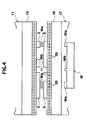
- Fig. 4 is a view showing the state where a plurality of upper navigating light-emitting devices and a plurality of lower navigating light-emitting devices that correspond to a work positioning reference position in the horizontal direction emit light
- Fig. 5 is a block diagram showing an NC device in accordance with the first embodiment of the present invention.
- a bending machine 1 in accordance with the embodiment of the present invention is a machine for performing bending of a plate-like work W by cooperation of an upper bending molds 3 and a lower bending molds 5 and uses a pair of side frames 7 separated right and left as a base.
- the pair of side frames 7 are connected integrally by a plurality of connecting members 9.
- An upper table 11 extending in the horizontal direction is provided on an upper part of the pair of side frames 7, an upper mold holder 13 extending in the horizontal direction is detachably provided on the lower side of the upper table 11, and the upper mold holder 13 has a holding groove 13s extending in the horizontal direction for holding the upper bending molds 3.
- An upper bending mold fixture 15 for fixing the upper bending mold 3 with respect to the upper mold holder 13 so as not to move in the horizontal direction is provided at a rear part of the upper mold holder 13.
- a lower table 17 extending in the horizontal direction is provided at a lower part of the pair of side frames so as to be opposed to the upper table in the vertical direction and the lower table 17 is capable of moving in the vertical direction via a guide member (not shown).
- a lower mold holder 19 extending in the horizontal direction is detachably provided on the upper side of the lower table 17 and the lower mold holder 19 has a holding groove 19s extending in the horizontal direction for holding the lower bending molds 5.
- a lower bending mold fixture 21 for fixing the lower bending mold 5 with respect to the lower mold holder 19 so as not to move in the horizontal direction is provided at a rear part of the lower mold holder 19.
- a bending cylinder 25 with an operating rod 23 capable of moving in the vertical direction is provided at each of the pair of side frames 7 and the operating rod 23 of each bending cylinder 25 is connected to a proper position of the lower table 17.
- the upper table 11 in place of the lower table 17 may be moved in the vertical direction.
- a back gauge device for positioning a workpiece W in the longitudinal direction with respect to the lower bending mold is provided in the rear of the lower bending mold 5 and this back gauge device has a striking member against which a rear end face of the workpiece W strikes so as to adjust the position in the longitudinal direction.
- a lot of navigating light-emitting devices 27 for guiding the operator by light emission is provided on a front face of the upper mold holder 13 of the upper table 11 and a lot of navigating light-emitting devices 29 for guiding the operator by light emission is provided on a front face of the lower mold holder 19 of the lower table 17.
- light-emitting diodes are used as the navigating light-emitting devices 27 and the navigating light-emitting devices 29.
- the bending machine 1 has an NC device 31 as shown in Fig. 5 and the NC device 31 has a CPU 33, an input part 35, a storage part 37, a mold determination part 39, a bending order determination part 41, a layout information determination part 43, a positioning information calculation part 45 and a light-emitting device control part 49 as main components and a cylinder control part for controlling the bending cylinder and a back gauge control part for controlling the back gauge device as components not shown.
- the input part 35 is electrically connected to the CPU 33 and inputs mechanical information, product information and the like.
- the "mechanical information” refers information representing mechanical elements of the bending machine 1, including information such as dimensions of predetermined places of the upper table 11 and the lower table 17 and Young's modulus of the upper table 11 and the lower table 17.
- the "product information” refers information representing shape of the product, including material of the product, thickness of the product, tensile strength of the product, length of bent flange, predetermined bending angle, etc.
- the storage part 37 is electrically connected to the CPU 33 and stores various information therein.
- the mold determination part 39 is electrically connected to the CPU 33 and determines the bending molds (upper bending mold 3 and the lower bending mold 5) used for bending on the basis of the above-mentioned product information
- the bending order determination part 41 is electrically connected to the CPU 33 and determines the bending order of the workpiece W on the basis of the above-mentioned product information.
- the layout information determination part 43 is electrically connected to the CPU 33 and determines mold layout information representing a layout mode of the bending molds 3 and 5 in the horizontal direction on the basis of the bending molds 3, 5 determined by the mold determination part 39, the bending order determined by the bending order determination part 41 (in other words, on the basis of the above-mentioned product information).
- the "mold layout information” includes information such as offset amount of the center of the bending molds 3 and 5 with respect to the machine center of the bending machine 1.
- the positioning information calculation part 43 is electrically connected to the CPU 33 and calculates work positioning information representing a positioning mode of the workpiece W with respect to the lower bending mold 5 on the basis of the bending molds 3, 5 determined by the mold determination part 39, the bending order determined by the bending order determination part 41 and the mold layout information determined by the layout information determination part 43 (in other words, on the basis of the above-mentioned product information and the above-mentioned mold layout information).
- the "work positioning information” includes information such as offset amount of the center of the workpiece W with respect to the machine center of the bending machine 1.
- the layout information determination part 43 determines the mold layout information representing the layout mode of the bending molds 3, 5 in the horizontal direction on the basis of the used bending molds 3, 5 and the bending order
- the positioning information calculation part 45 calculates the work positioning information representing the positioning mode of the workpiece W with respect to the lower bending mold 5 on the basis of the used bending molds 3, 5, the bending order and the mold layout information.
- a skilled operator may store the bending order, mold selection and mold layout in the storage part 37 through the input part 35 shown in Fig. 5 on the basis of knowledge built up over many years so that the positioning information calculation part 45 calculates the work positioning information representing the positioning mode of the workpiece W with respect to the lower bending mold 5 on the basis of the used bending molds 3, 5, the bending order and the mold layout information. Further, a skilled operator may store the work positioning information representing the positioning mode of the workpiece W with respect to the lower bending mold 5 in the storage part 37 through the input part 35 shown in Fig. 5 on the basis of knowledge built up over many years.
- the light-emitting device control part 47 is electrically connected to the CPU 33 and specifically, has the following configuration.
- the light-emitting device control part 47 is configured controllably so that the plurality of the navigating light-emitting devices corresponding to mold attachment reference positions in the horizontal direction emit light on the basis of the mold layout information among the plurality of the navigating light-emitting devices (the plurality of the upper navigating light-emitting devices 27 and the plurality of the lower navigating light-emitting devices 29) emit light (refer to Fig. 3).
- the "mold attachment reference position in the horizontal direction” refers a position that serves as a reference (including region) when the bending molds 3, 5 each are attached to the mold holders 13,19 of the tables 11,13, respectively according to the above-mentioned layout mode, and in the embodiment of the present invention, the same number of the mold attachment reference positions as the number of the bending molds 3, 5 are used.
- the light-emitting device control part 47 is configured controllably so that the appropriate number of the lower navigating light-emitting devices 29 corresponding to the work positioning reference positions in the horizontal direction on the basis of the work positioning information emit light among the plurality of the lower navigating light-emitting devices 29 emit light as well as the appropriate number of the lower navigating light-emitting devices 29 corresponding to the mold interference reference positions in the horizontal direction on the basis of the work positioning information emit light in a special luminous state (refer to Fig. 4).
- the "work positioning reference position in the horizontal direction” refers a position that serves as a reference (including region) when the workpiece W is positioned in the horizontal direction with respect to the lower bending mold 5 according to the above-mentioned work positioning mode, and in the embodiment of the present invention, when a plurality of bending parts (parts subjected to bending) Wa exists at a piece of the workpiece W, the same number of work positioning reference positions as the number of the bending parts Wa are used.
- the “mold interference reference position in the horizontal direction” refers a position that serves as a reference (including region) at which non-bending parts (parts not subjected to bending) Wb at the workpiece W interfere the bending molds 3, 5 when the workpiece W is positioned in the horizontal direction with respect to the lower bending mold 5 according to the above-mentioned work positioning mode, and in the embodiment of the present invention, when a plurality of non-bending parts Wb exists at a piece of the workpiece W, the same number of mold interference reference positions as the number of the non-bending parts Wb are used.
- the "emit light in a special luminous state” includes emitting light at varied flashing speed of the lower navigating light-emitting devices 29 and emitting light with varied luminescent colors of the lower navigating light-emitting devices 29.
- the bending molds (used bending molds) 3, 5 used for bending is determined by the mold determination part 39 on the basis of the above-mentioned product information and the bending order of the workpiece W is determined by the bending order determination part 41 on the basis of the above-mentioned product information.
- the mold layout information is determined by the layout information determination part 43 on the basis of the used bending molds 3, 5 and the bending order and the work positioning information is calculated by the positioning information calculation part 45 on the basis of the used bending molds 3, 5, the bending order and the mold layout information.
- the light-emitting device control part 47 controls the plurality of navigating light-emitting devices 27, 29 corresponding the mold attachment reference positions in the horizontal direction on the basis of the mold layout information emit light.
- the operator can attach the molds to the mold holders according to the layout mode while being guided by light emission of the plurality of the navigating light-emitting devices 27, 29 corresponding to the mold attachment reference positions in the horizontal direction.
- the same number of times as the number of the bending molds as shown in Fig. 3, three upper bending molds can be attached to the upper mold holder 13 and three lower bending molds can be attached to the lower mold holder 19 according to the layout mode.
- the light-emitting device control part 47 controls so that the appropriate number of the lower navigating light-emitting devices 29 corresponding to the work positioning reference positions in the horizontal direction on the basis of the work positioning information emit light.
- the operator can position the workpiece W in the horizontal direction with respect to the lower bending molds 5 while being guided by light emission of the plurality of corresponding navigating light-emitting devices.
- the light-emitting device control part 47 controls so that the appropriate number of the lower navigating light-emitting devices 29 corresponding to a mold interference reference positions in the horizontal direction on the basis of the work positioning information emit light in a special luminous state.
- the operator can position the workpiece W so that the non-bending parts Wb do not enter to the mold interference reference positions in the horizontal direction while being guided by light emission of the appropriate number of lower navigating light-emitting devices 29 corresponding to the mold interference reference positions in a special luminous state.
- the positioning of the workpiece W in the longitudinal direction with respect to the lower bending molds by striking the end face of the workpiece W against the striking member of the back gauge device from the forward direction.
- the plurality of bending parts Wa may be bent simultaneously or the plurality of bending parts Wa may be bent sequentially.
- the plurality of navigating light-emitting devices 27, 29 corresponding to the mold attachment reference positions in the horizontal direction on the basis of the mold layout information can be made to emit light
- a plurality of bending molds (three upper bending molds and three lower bending molds in the embodiment of the present invention) can be attached to the mold holders 13, 19 according to the changed layout mode while being guided by light emission of the mold attachment reference positions in the horizontal direction on the basis of the mold layout information representing the changed layout mode. For this reason, even when plural types of bending is performed while changing the layout mode, a series of bending processes can be efficiently performed in a short time.
- the workpiece W has a plurality of bending parts Wa or non-bending parts Wb
- positioning of the workpiece W in the horizontal direction with respect to the lower bending molds 5 can be performed with a high degree of accuracy, and for example, the plurality of bending parts Wa at the workpiece W can be easily bent simultaneously or the bending parts Wa at the workpiece W can be easily bent while avoiding interference between the non-bending parts Wb and the bending molds 3, 5.
- the operator can position the workpiece W so that the non-bending parts Wb do not enter to the mold interference reference positions in the horizontal direction while being guided by light emission of the appropriate number of lower navigating light-emitting devices 29 corresponding to the mold interference reference positions in a special luminous state, the above-mentioned effects can be further improved.
- Fig. 6 is a view showing the state where an upper navigating guide part and a lower navigating guide part are located at positions corresponding to the mold attachment reference positions in the horizontal direction
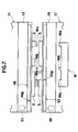
- Fig. 7 is a view showing the state where the lower navigating guide part is located at a position corresponding to the work positioning reference position in the horizontal direction
- Fig. 8 is a block diagram of an NC device in accordance with the second embodiment of the present invention.
- the bending machine in accordance with the second embodiment of the present invention has the substantially same configuration as the bending machine 1 in accordance with the first embodiment of the present invention and among all components of the bending machine in accordance with the second embodiment of the present invention, components other than the components in the bending machine 1 in accordance with the first embodiment of the present invention will be described below.
- components similar to the components in the bending machine 1 in accordance with the first embodiment of the present invention are given same reference numerals in the figures and description thereof is not repeated.
- an annular upper navigating belt 49 capable of traveling in the horizontal direction is provided on the front face of the upper mold holder 13 in the bending machine in accordance with the second embodiment of the present invention and this upper navigating belt 49 has a navigating guide part 49g for guiding the operator.
- a traveling servo motor 51 for driving the upper navigating belt 49 in the horizontal direction is provided at an appropriate position of the upper mold holder 13.
- annular lower navigating belt 53 capable of traveling in the horizontal direction is provided on the front face of the lower mold holder 19 and this lower navigating belt 53 has a navigating guide part 53g for guiding the operator.
- a traveling servo motor 55 for driving the lower navigating belt 53 in the horizontal direction is provided at an appropriate position of the lower mold holder 19.
- the bending machine in accordance with the second embodiment of the present invention has an NC device 57 shown in Fig. 8 and similar to the NC device in accordance with the first embodiment of the present invention, this NC device 57 has the CPU 33, the input part 35, the storage part 37, the mold determination part 39, the bending order determination part 41, the layout information determination part 43 and the positioning information calculation part 45 as main components and also has a traveling servo motor control part 59 as a main component.
- the traveling servo motor control part 59 is electrically connected to the CPU 47 and specially, has the following configuration.
- the traveling servo motor control part 59 can control the traveling servo motors 51, 55 so as to locate the navigating guide parts 49g, 53g at positions corresponding to the mold attachment reference positions in the horizontal direction on the basis of the mold layout information.
- the "mold attachment reference position in the horizontal direction” refers to a position (including region) that serves as a reference when the bending molds 3, 5 are attached to the mold holders 13,19 of the tables 11, 13 according to the layout mode, and in the embodiment of the present invention, the same number of the mold attachment reference positions as the number of the bending molds 3, 5 are used.
- the traveling servo motor control part 59 can control the traveling servo motor 55 so as to locate the navigating guide part 53g at a position corresponding to the work positioning reference position in the horizontal direction on the basis of the work positioning information.
- the "work positioning reference position in the horizontal direction” refers to a position (including region) that serves as a reference when the workpiece W is positioned with respect to lower bending mold 5 in the horizontal direction according to the above-mentioned work positioning mode, and in the embodiment of the present invention, even when a plurality of bending parts (parts subjected to bending) Wa exist at a piece of work W, one work positioning reference position is used.
- the used bending molds 3, 5 are determined and the bending order of the workpiece W is determined.
- the mold layout information representing the layout mode of the bending molds 3, 5 in the horizontal direction is determined by the layout information determination part 39 on the basis of the used bending molds 3, 5 and the bending order and the work positioning information representing the positioning mode of the workpiece W with respect to the lower bending mold 5 is calculated by the positioning information calculation part 45 on the basis of the used bending molds 3, 5, the bending order and the above-mentioned mold layout information.
- the traveling servo motor control part 59 controls the traveling servo motors 51, 55 so as to locate the navigating guide parts 49g, 53g at positions corresponding to the mold attachment reference positions in the horizontal direction.
- the operator can attach the bending molds 3, 5 to the mold holders 13,19 according to the layout mode while being guided by the navigating guide parts 49g, 53g.
- three upper bending molds 3 can be attached to the upper mold holder and three lower bending molds 5 can be attached to the lower mold holder 19 according to the layout mode.
- the traveling servo motor control part 59 controls the traveling servo motor 55 so as to locate the navigating guide part 53g at the position corresponding to the work positioning reference position in the horizontal direction.
- the operator can position the workpiece W in the horizontal direction with respect to the lower bending molds 5 while being guided by the navigating guide part 53g.
- the positioning of the workpiece W in the longitudinal direction with respect to the lower bending molds by striking the end face of the workpiece W against the striking member of the back gauge device from the forward direction.
- the navigating guide parts 49g, 53g can be located at positions corresponding to the mold attachment reference positions in the horizontal direction on the basis of the mold layout information, even when the layout mode is changed, a plurality of bending molds (three upper bending molds and three lower bending molds in the embodiment of the present invention) can be attached to the mold holders 13,19 according to the changed layout mode while being guided by the navigating guide parts 49g, 53g located at positions corresponding the mold attachment reference positions in the horizontal direction on the basis of the mold layout information representing the changed layout mode. For this reason, even when plural types of bending is performed while changing the layout mode, a series of bending processes can be efficiently performed in a short time without adding complicated operations.
- the operator can position the workpiece W in the horizontal direction with respect to the lower bending molds 5 according to the positioning mode while being guided by the navigating guide part 53g located at the position corresponding to the work positioning reference position, operating time for positioning the workpiece W becomes shorter, thereby to improve operating efficiency.
- the workpiece W has a plurality of bending parts Wa or non-bending parts Wb
- positioning of the workpiece W in the horizontal direction with respect to the lower bending molds 5 can be performed with a high degree of accuracy, and for example, the plurality of bending parts Wa at the workpiece W can be easily bent simultaneously or the bending parts Wa at the workpiece W can be easily bent while avoiding interference between the non-bending parts Wb and the bending molds 3, 5.
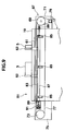
- Fig. 9 is a view showing a main part of a bending machine in accordance with the third embodiment of the present invention
- Fig. 10 is a view taken along the line I-I of Fig. 9
- Fig. 11 is a perspective view showing the state where a navigating pin (navigating member) is located at a position corresponding to the mold attachment reference position in the horizontal direction
- Fig. 12 is a perspective view showing the state where a navigating pin is located at a position corresponding to the work positioning reference position in the horizontal direction
- Fig. 13 is a block diagram of an NC device in accordance with the third embodiment of the present invention.
- the bending machine in accordance with the third embodiment of the present invention (the whole of the bending machine is not shown) has the substantially same configuration as the bending machine 1 in accordance with the first embodiment of the present invention and among all components of the bending machine in accordance with the third embodiment of the present invention, components other than the components in the bending machine 1 in accordance with the first embodiment of the present invention will be described below.
- components similar to the components in the bending machine 1 in accordance with the first embodiment of the present invention are given same reference numerals in the figures and description thereof is not repeated.
- a pin guide 61 extending in the horizontal direction is provided at the front face of the lower mold holder 19 and the pin guide 61 is provided with a navigating pin 63 for guiding the operator so as to be movable in the horizontal direction.
- the navigating pin 63 is comprised of a first vertical part 63a supported by the pin guide 61 so as to be movable in the horizontal direction, a second vertical part 63b arranged in a slightly rearward position to the first vertical part 63a and a horizontal part 63c connecting the first vertical part 63a and the second vertical part 63b.
- An L-like clamped piece 65 is formed integrally with a lower side of the first vertical part 63a in the navigating pin 63 and the second vertical part 63b in the navigating pin 63 has a striking face F that can be struck by the end face of the workpiece W from the right direction.
- a pin transfer device 67 for transferring the navigating pin 63 in the horizontal direction is provided at the lower table 17.
- a driving pulley 69 is provided rotatably on the right side of the lower table 17 via a bracket 71 and a driven pulley 73 separate from the driving pulley 69 is provided rotatably on the left side of the lower table 17 via a bracket 75.
- a circular timing belt 77 is formed so as to wind around the driving pulley 69 and the driven pulley 73 and a part of the timing belt 77 is connected to the navigating pin 63.
- a traveling servo motor 79 is provided on the lower table 17 via a bracket 71 and the driven pulley 69 is interlocked to an output shaft of the traveling servo motor 79 through an appropriate connecting means.
- the navigating pin 63 can be moved by the driving of the traveling servo motor 79 in the horizontal direction through the driving pulley 69, the driven pulley 73 and the timing belt 77.
- a pin fixing device 81 is provided for fixing the navigate pin 63 so as not to move in the horizontal direction with respect to the lower table 17.
- a fixing bar 83 extending in the horizontal direction is provided on the front face of the lower table 17 and a fixing piece 83a extending in the horizontal direction is provided on the fixing bar 83.
- a plurality of swinging links 85 capable of swinging in the vertical direction is provided below the fixing piece 83a and base parts of the plurality of swinging links 85 are each rotatably connected to the lower table 17.
- a clamping bar 87 extending in the horizontal direction is provided at front end parts of the plurality of swinging links 85 and serves to clamp the clamped piece 65 in the vertical direction in cooperation with the fixing piece 83a.
- a clamping air cylinder 91 with a piston rod 89 connected to the left end of the clamping bar 87 is provided on the left side of the lower table 17 via the bracket 7 and serves to transfer the clamping bar 87 in the vertical direction while swinging the plurality of swinging links 85 in the vertical direction.
- a spring 93 urging the clamping bar 87 in the right direction (unclamping direction of releasing clamping) is provided at an appropriate position on the right side of the lower table 17.
- the clamping bar 87 is transferred upwards while swinging the plurality of swinging links 85 upwards by the operation of the clamping air cylinder 91.
- This enables clamping the clamped piece 65 in cooperation of the clamp bar 87 and the fixing piece 83a and fixing the navigating pin 63 so as not to move in the horizontal direction with respect to the lower table 17.
- the clamping bar 87 is transferred downwards by urging force of the spring 93 while swinging the plurality of swinging links 85 downwards and the operation of the clamping air cylinder 91. This enables releasing the clamping state of the clamped piece 65 and making the navigating pin 63 movable in the horizontal direction with respect to the lower table 17.
- the bending machine in accordance with the third embodiment of the present invention has an NC device 95 shown in Fig. 13 and similar to the NC device 31 in accordance with the first embodiment of the present invention, this NC device 95 has the CPU 33, the input part 35, the storage part 37, the mold determination part 39, the bending order determination part 41, the layout information determination part 43 and the positioning information calculation part 45 as main components and also has a traveling servo motor control part 97 for controlling the traveling servo motor 79 as a main component.
- the traveling servo motor control part 97 is electrically connected to the CPU 33 and specially, has the following configuration.
- the traveling servo motor control part 97 can control the traveling servo motor 79 so as to locate the navigating pin 63 at a position corresponding to the mold attachment reference position in the horizontal direction on the basis of the mold layout information (refer to Fig. 11).
- the "mold attachment reference position in the horizontal direction” refers to a position (including region) that serves as a reference when the bending molds 3, 5 are attached to the mold holders 13, 19 of the tables 11,13 according to the layout mode, and in the embodiment of the present invention, the same number of the mold attachment reference positions as the number of the bending molds 3, 5 are used.
- the traveling servo motor control part 97 can control the traveling servo motor 79 so as to locate the navigating pin 63 at a position corresponding to the work positioning reference position in the horizontal direction on the basis of the work positioning information (refer to Fig. 12).
- the "work positioning reference position in the horizontal direction” refers to a position (including region) that serves as a reference when the workpiece W is positioned with respect to lower bending mold 5 in the horizontal direction according to the above-mentioned work positioning mode, and in the embodiment of the present invention, even when a plurality of bending parts (parts subjected to bending) Wa exist at a piece of work W, one work positioning reference position is used.
- the used bending molds 3, 5 are determined and the bending order of the workpiece W is determined.
- the mold layout information representing the layout mode of the bending molds 3, 5 in the horizontal direction is determined by the layout information determination part on the basis of the used bending molds 3, 5 and the bending order, and the work positioning information representing the positioning mode of the workpiece W with respect to the lower bending mold 5 is calculated by the positioning information calculation part 45 on the basis of the used bending molds 3, 5, the bending order and the above-mentioned mold layout information.
- the traveling servo motor control part 97 controls the traveling servo motor 79 so as to locate the navigating pin 63 at a position corresponding to the mold attachment reference position in the horizontal direction.
- the operator can attach the bending molds to the mold holders 1, 19 according to the layout mode while being guided by the navigating pin 63.
- two upper bending molds 3 can be attached to the upper mold holder 13 (not shown) and two lower bending molds 5 can be attached to the lower mold holder 19 (refer to Fig. 11) according to the layout mode.
- the traveling servo motor control part 97 controls the traveling servo motor 79 so as to locate the navigating pin 63 at the position corresponding to the work positioning reference position in the horizontal direction.
- the operator can position the workpiece W in the horizontal direction with respect to the lower bending molds 5 while being guided by the navigating pin 63.
- the end face of the workpiece W is struck against the striking face F of the navigating pin 63 from the right direction in the state where the navigating pin 63 is fixed by the pin fixing means 81 so as not to move in the horizontal direction with respect to the lower table 17.
- the positioning of the workpiece W in the longitudinal direction with respect to the lower bending molds by striking the end face of the workpiece W against the striking member of the back gauge device from the forward direction.
- a desired bending of the workpiece W is performed in cooperation of the upper bending molds 3 and the lower bending molds 5.
- the plurality of bending parts Wa may be bent sequentially or in the case of the workpiece W as shown in Fig. 4, the plurality of bending parts Wa may be bent simultaneously.
- the navigating pin 63 can be located at the position corresponding to the mold attachment reference position in the horizontal direction on the basis of the mold layout information, even when the layout mode is changed, a plurality of bending molds (two upper bending molds and two lower bending molds in the embodiment of the present invention) can be attached to the mold holders 13, 19 according to the changed layout mode while being guided by the navigating pin 63 located at the position corresponding the mold attachment reference position in the horizontal direction on the basis of the mold layout information representing the changed layout mode. For this reason, even when plural types of bending is performed while changing the layout mode, a series of bending processes can be efficiently performed in a short time without adding complicated operations.
- the operator can position the workpiece W in the horizontal direction with respect to the lower bending molds 5 according to the positioning mode while being guided by the navigating pin 63 located at the position corresponding to the work positioning reference position, operating time for positioning the workpiece W becomes shorter, thereby to improve operating efficiency.
- the workpiece W has a plurality of bending parts Wa or non-bending parts Wb
- positioning of the workpiece W in the horizontal direction with respect to the lower bending molds 5 can be performed with a high degree of accuracy, and for example, the plurality of bending parts Wa at the workpiece W can be easily bent simultaneously or the bending parts Wa at the workpiece W can be easily bent while avoiding interference between the non-bending parts Wb and the bending molds 3, 5.
- the fixing bar 83 and the clamping bar 87 extend in the horizontal direction and the clamped piece 65 is clamped in the vertical direction by cooperation of the clamping bar 87 and the fixing piece of the fixing bar 83, a length of the pin fixing device 81 in the longitudinal direction can be reduced as much as possible. For this reason, when the workpiece W is bent, the part bent previously can be prevented from interfering with the pin fixing device 81.
- Fig. 14 is a perspective view of a navigating mechanism 101.
- a toothed pulley 127 driven rotatably is provided at the lower table 17 and a toothed endless belt 129 is hanged on the toothed pulley 127.
- a rail 131 extending in the horizontal direction of the device is attached to the lower table 17.
- a pair of sliders 133 capable of sliding in the horizontal direction of the device are provided at the rail 131 and a carriage 135 is attached to the pair of sliders 133.
- the endless belt 129 is fixed at the lower part of the carriage 135.
- a lifting 137 that can freely move up and down the carriage 135 substantially in the vertical direction is provided slidably at the carriage 135 and a head part 141 is formed at the upper part of the carriage 135.
- a roller 139 is axially supported so as to rotate freely at the lower part of the carriage 135.
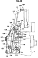
- an L-like member 119 in the shape of a bell crank is axially supported around a supporting shaft 117 so as to rotate freely.
- the cylinder 107 is swingably provided at the lower table 17 and a connector 111 is fixed to a piston rod 109. Further, a horizontal traveling bar 113 extending in the horizontal direction is fixed to the connector 111.
- a midpoint of the L-like member 119 is pivotally supported by the horizontal traveling bar 113 via a shaft 121.
- a front end of the L-like member 119 is pivotally supported by a vertical traveling bar 125 via a shaft 123.
- the vertical traveling bar 125 is located below the roller 139.
- the lifting member 137 since the roller 139 that comes in contact with an upper face of the vertical traveling bar 125 also ascends, the lifting member 137 also ascends (positions represented by chain double-dashed lines).
- the head part 141 When the lifting member 137 ascends, as shown Fig. 17A, C, the head part 141 also ascends and a locating member 145 pivotally supported by the head part 141 via a shaft 151 moves to the position to be contacted with the workpiece W.
- the workpiece W is placed on a mounting base 147 provided at the head part 141.
- a top face of the mounting base 147 is formed to have the same level as the top face of the lower bending mold 5. Therefore, since the work comes in contact with the lower bending mold 5 accurately by placing the work on the mounting base 147, positioning can be achieved accurately. This improves bending accuracy.
- the operator can arrange and fix the lower bending mold 5 at a predetermined position. Also, by moving the workpiece W in the vertical direction in the Fig. 17A and bringing the workpiece W into contact with the locating member 145 represented by a solid line in Fig. 17C, the operator can position the workpiece W at a predetermined position.
- the cylinder 107 When positioning and bending is finished, the cylinder 107 is constricted and the lifting member 137 is lowered to a position represented by a solid line in Fig. 14. Subsequently, the servo motor 79 is rotationally driven by the traveling servo motor control part 97 shown in Fig. 13, thereby to rotate the pulley 127. Whereby, the lifting member 137 is moved to a desired appropriate position in the horizontal direction through the belt 129 and the carriage 135. Following the positioning of the lifting member 137 in the horizontal direction, the cylinder 107 is extended again and the lifting member 137 is raised to repeat the same operation process.
- the lifting member 137 Since the lifting member 137 is lowered when moving in the horizontal direction, the lifting member 137 is covered with a cover 159 formed of rubber, flexible resin and the like. Since the other above-mentioned mechanisms are covered with covers 153,155, contact with the operator is avoided for safety.
- a manual pulse switch button 160 when pressed, the servo motor 79 is operated and the locating member 145 (navigating member) returns to an origin in the horizontal direction (Y-axis) (S3). Subsequently, in the state where the window for manual setting 157 is observed to operate the traveling servo motor 79 by manual setting operation, a manual pulsar is rotated and the traveling servo motor 79 is operated while a displayed value 167 showing a present position of the locating member 145 in the horizontal direction (Y-axis) is checked, and when the locating member 145 (navigating member) reaches a desired position, operation of the manual pulsar is stopped, thereby to stop rotation of the servo motor 79 (S4).
- a correction value is manually input into the storage part 37 (Fig. 13) by pressing an execution button 163 as a setting button (S5).
- the locating member 145 is automatically positioned at the above-mentioned correction position. Accordingly, providing that an experienced person performs the first correction operation by manual pulse, even a beginner can perform bending like an experienced person in the next processing.
- an experienced operator instructs "Valid/Invalid" of work navigating function according to each bending order 1 to 4 displayed as 1 to 4 in a left-end column of a table shown below the window 157 to set a target position of positioning of the work navigating function.
- which of a left and right side faces of the work navigating striking member the end face or end side of the work strikes against, to what extent each pull side amount (avoidance transfer amount) is, whether or not the work navigating member is raised higher than a normal work navigating position by 5mm, and the like are set arbitrarily and the setting values is stored in the storage part 37.
- suitable processing can apply to the product by calling the above-mentioned values in the processing from the storage part 37.
- back gauges 173, 175 are provided to be movable in the Y-axis direction to a carriage 171 that can be freely move in the X-axis direction.
- Striking members 177, 179 are provided at front end parts of the back gauges 173, 175, respectively.
- locating members 181, 183 capable of moving in the X-axis direction are each provided at the corresponding striking members 177, 179.
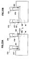
- the striking member 177 is moved to the position represented by a chain double-dashed line. Subsequently, the operator slides the lower bending mold 5 in the Y-axis direction to be struck against the striking member 177. Whereby, the lower bending mold 5 can be positioned at a predetermined position in the Y-axis direction.
- the bending line 185 requires matching with the bending position of the lower bending mold 5.
- positioning in the X-axis direction is performed by striking the workpiece W against the striking members 177, 179 and positioning in the Y-axis direction is performed by striking the workpiece W against the locating member 183.
- the other locating member 181 is retreated as shown in Fig. 22A.
- the traveling servo motor control part 97 shown in Fig. 13 is modified to be triaxial and three traveling servo motors 79 are provided. As a result, movement of the carriage 171 in the X-axis direction and movement of each of the back gauges 173, 175 in the Y-axis direction, that is, movement in the three-axis directions in total, are controlled.
- the bending information, the mold layout information, the product information and the work positioning information are input (S11) and in the CPU 33, a position in the Y-axis direction that satisfies the predetermined appropriate positional relationship of the workpiece W with respect to the lower bending mold (work navigating striking position) is calculated (S12).
- the operator can easily recognize which side of the plural sides of the work should be struck against what place of the work navigating striking member (left side face or right side face) and therefore, positioning of the work in the horizontal direction can be performed properly.
- the operator allows the work to strike against the locating member 145 in the Y-axis direction according to the work navigating striking position thus determined.
- the work can be positioned with respect to the lower bending mold 5 in the Y-axis direction.
- the present invention is not limited to the above-mentioned embodiments of the present invention and can be available in other various modes by making necessary modifications.
- a work following device exists as a device generally annexed to the bending machine. Since both ends of the work rotate upwards making the mold as a boundary when the work is bent, a hand of a robot also follows upwards while holding the work. Like the above-mentioned back gauge, this work following device can move to a predetermined position both in the Y-axis direction and in the X-axis direction. Therefore, by providing the locating member (navigating pin) at the hand of the robot, effects similar to those in the second to fourth embodiments can be achieved.
Landscapes
- Engineering & Computer Science (AREA)
- Mechanical Engineering (AREA)
- Bending Of Plates, Rods, And Pipes (AREA)
- Shaping Of Tube Ends By Bending Or Straightening (AREA)
Abstract
Description
Claims (10)
- A bending machine for bending a workpiece by cooperation of an upper bending mold and a lower bending mold which are movable relatively in the vertical direction, comprising:an upper table which has an upper mold attachment part for attaching the upper bending mold on the bottom side thereof and extends in the horizontal direction;a lower table which is formed so as to be opposed to the upper table in the vertical direction, has a lower mold attachment part for attaching the lower bending mold on the top side thereof and extends in the horizontal direction;an input part for inputting product information;a bending order determination part for determining a bending order of the workpiece;a mold determination part for determining the mold necessary for bending the workpiece;a layout determination part for determining layout of the mold;a positioning information calculation part for calculating a position of the workpiece with respect to the mold determined by the layout determination part as work position information; anda navigating member for navigating position of the workpiece to the operator by movement in the horizontal direction on the basis of the work position information calculated by the positioning information calculation part.
- A bending machine according to claim 1, wherein
the navigating member is formed on a front face of the lower table so as to be movable in the horizontal direction, has a striking face to which an end face of the workpiece can strike from the left or right direction; and
the navigating member can be freely ascended in the direction of an upper face of a die after positioning in the horizontal direction. - A bending machine according to claim 2, wherein
a locating member is formed at a front end of the navigating member and has a mounting table for maintaining height of the workpiece appropriately when the workpiece is struck against an end face of the locating member. - A bending machine according to claim 2, wherein
a locating member is rotatably formed at the front end of the navigating member and by rotating the locating member and striking the workpiece against the end face of the locating member, position of the mold can be guided to the operator. - A bending machine according to claim 1, wherein
the navigating member is a back gauge provided in the rear side of the lower table so as to be movable in the horizontal direction and the longitudinal direction. - A bending machine according to claim 1, wherein
the navigating member is a light-emitting device for guiding position of the workpiece to the operator by emitting light at an appropriate position. - A bending machine according to claim 1, wherein
the navigating member is a belt with a navigating guide part and the navigating guide part stops at an appropriate position, thereby to guide position of the workpiece to the operator. - A bending machine for bending a workpiece by cooperation of an upper bending mold and a lower bending mold, comprising:an upper table which has an upper mold attachment part for attaching the upper bending mold on the bottom side thereof and extends in the horizontal direction;a lower table which is formed so as to be opposed to the upper table in the vertical direction, has a lower mold attachment part for attaching the lower bending mold on the top side thereof, extends in the horizontal direction and can be move relatively in the vertical direction with respect to the upper table;a navigating member which is provided on a front face of at least either of the upper table or the lower table so as to be movable in the horizontal direction and guides the operator;a traveling actuator for transferring the navigating member in the horizontal direction;a mold layout determination part for determining mold layout information representing a layout mode of the lower bending mold and the upper bending mold in the horizontal direction on the basis of product information representing shape of the product and the like; anda traveling actuator control means for controlling the traveling actuator so as to locate the navigating member at a position corresponding to a mold attachment reference position in the horizontal direction on the basis of the mold layout information.
- A bending machine for bending a workpiece by cooperation of an upper bending mold and a lower bending mold, comprising:an upper table which has an upper mold attachment part for attaching the upper bending mold on the bottom side thereof and extends in the horizontal direction;a lower table which is formed so as to be opposed to the upper table in the vertical direction, has a lower mold attachment part for attaching the lower bending mold on the top side thereof, extends in the horizontal direction and can be move relatively in the vertical direction with respect to the upper table;a navigating member which is provided on a front face of at least either of the upper table or the lower table so as to be movable in the horizontal direction and guides the operator;a traveling actuator for transferring the navigating member in the horizontal direction;a mold layout determination part for determining mold layout information representing a layout mode of the lower bending mold and the upper bending mold in the horizontal direction on the basis of product information representing shape of the product and the like;a positioning information calculation means for calculating work positioning information representing a positioning mode of the workpiece with respect to the lower bending mold on the basis of the product information and the mold layout information; anda traveling actuator control means for controlling the traveling actuator so as to locate the navigating member at a position corresponding to a work positioning reference position in the horizontal direction on the basis of the mold layout information.
- A bending machine according to claim 9, wherein
the navigating member is formed on a front face of the lower table so as to be movable in the horizontal direction, has a striking face to which an end face of the workpiece can strike from the left or right direction; and
the navigating member can be freely ascended in the direction of an upper face of a die after positioning in the horizontal direction.
Applications Claiming Priority (5)
| Application Number | Priority Date | Filing Date | Title |
|---|---|---|---|
| JP2002308988 | 2002-10-23 | ||
| JP2002308988 | 2002-10-23 | ||
| JP2003357269A JP4630533B2 (en) | 2002-10-23 | 2003-10-17 | Bending machine |
| JP2003357269 | 2003-10-17 | ||
| PCT/JP2003/013550 WO2004037457A1 (en) | 2002-10-23 | 2003-10-23 | Bending machine |
Publications (3)
| Publication Number | Publication Date |
|---|---|
| EP1563921A1 true EP1563921A1 (en) | 2005-08-17 |
| EP1563921A4 EP1563921A4 (en) | 2009-01-14 |
| EP1563921B1 EP1563921B1 (en) | 2012-01-04 |
Family
ID=32179090
Family Applications (1)
| Application Number | Title | Priority Date | Filing Date |
|---|---|---|---|
| EP03758818A Expired - Lifetime EP1563921B1 (en) | 2002-10-23 | 2003-10-23 | Bending machine |
Country Status (5)
| Country | Link |
|---|---|
| US (1) | US7392678B2 (en) |
| EP (1) | EP1563921B1 (en) |
| JP (1) | JP4630533B2 (en) |
| AT (1) | ATE539829T1 (en) |
| WO (1) | WO2004037457A1 (en) |
Cited By (2)
| Publication number | Priority date | Publication date | Assignee | Title |
|---|---|---|---|---|
| US7802456B2 (en) | 2004-12-27 | 2010-09-28 | Amada Company, Limited | Work bending angle detecting device and work bending machine |
| WO2011160243A1 (en) * | 2010-06-24 | 2011-12-29 | Jorns Ag Lotzwil | Tool carriage for processing tools of a processing machine |
Families Citing this family (13)
| Publication number | Priority date | Publication date | Assignee | Title |
|---|---|---|---|---|
| AT412453B (en) * | 2002-07-01 | 2005-03-25 | Trumpf Maschinen Austria Gmbh | MANUFACTURING DEVICE, IN PARTICULAR BUTTING PRESSURE, WITH ELECTRONIC TOOL CAPTURE |
| JP4969049B2 (en) | 2004-04-06 | 2012-07-04 | 株式会社アマダ | Bending machine |
| WO2006043408A1 (en) * | 2004-10-22 | 2006-04-27 | Amada Co., Ltd | Method and apparatus for bending |
| WO2006054596A1 (en) * | 2004-11-17 | 2006-05-26 | Amada Company, Limited | Bending method, and die and bending machine used for the bending method |
| CN100528395C (en) * | 2004-12-27 | 2009-08-19 | 株式会社阿玛达 | Workpiece bending angle detecting device and workpiece bending machine |
| JP4743688B2 (en) * | 2005-04-12 | 2011-08-10 | 株式会社アマダ | Bending machine |
| JP4804837B2 (en) * | 2005-09-01 | 2011-11-02 | 株式会社アマダ | Mold setup information creation device |
| JP5108260B2 (en) | 2006-07-06 | 2012-12-26 | 株式会社アマダ | Method and apparatus for utilizing bending machine mold layout |
| US9448650B2 (en) | 2012-11-09 | 2016-09-20 | Wilson Tool International Inc. | Display device for punching or pressing machines |
| JP6054156B2 (en) * | 2012-11-30 | 2016-12-27 | 株式会社日立製作所 | Machined component mounting position indication system in bending machine |
| US10857581B2 (en) * | 2016-11-15 | 2020-12-08 | Accurpress America Inc. | Machine for bending metal including an adjustable backgauge |
| CN112718943B (en) * | 2020-12-14 | 2024-06-04 | 上海丰昌船务工程有限公司 | Metal workpiece bending equipment for ship processing plant |
| JP2024066175A (en) * | 2022-11-01 | 2024-05-15 | 株式会社アマダ | Die position guide method and press brake |
Family Cites Families (19)
| Publication number | Priority date | Publication date | Assignee | Title |
|---|---|---|---|---|
| JP3181382B2 (en) * | 1992-07-15 | 2001-07-03 | 株式会社アマダ | Work positioning device for bending machine |
| JPH06226354A (en) | 1993-01-29 | 1994-08-16 | Amada Co Ltd | Bending device for metal plate |
| EP0744046B1 (en) | 1994-11-09 | 2003-02-12 | Amada Company Limited | Intelligent system for generating and executing a sheet metal bending plan |
| US5969973A (en) | 1994-11-09 | 1999-10-19 | Amada Company, Ltd. | Intelligent system for generating and executing a sheet metal bending plan |
| JPH09155452A (en) * | 1995-12-06 | 1997-06-17 | Amada Co Ltd | Method and equipment for fitting die of sheet metal working machine |
| GB2327123B (en) | 1996-02-13 | 2000-09-13 | Amada Metrecs Co | Angle detection method for bending machines, and angle detection apparatus and angle sensor thereof |
| US5983688A (en) * | 1996-07-08 | 1999-11-16 | Anzai; Tetsuya | Method and apparatus for displaying die layout in press brake and for checking interference |
| JPH10128454A (en) * | 1996-10-25 | 1998-05-19 | Amada Co Ltd | Back gage device provided with butt selecting function |
| US6807835B1 (en) * | 1997-12-19 | 2004-10-26 | Amada Company, Limited | Bending method and bending system |
| JP4355374B2 (en) * | 1998-02-06 | 2009-10-28 | 株式会社アマダ | Die mounting method for press brake |
| JP4097776B2 (en) * | 1998-04-30 | 2008-06-11 | 株式会社アマダ | Press brake |
| JP2000015340A (en) * | 1998-07-08 | 2000-01-18 | Amada Co Ltd | Bending method and apparatus thereof |
| JP2000237820A (en) * | 1999-02-18 | 2000-09-05 | Amada Co Ltd | Device and method for positioning work and storage medium |
| JP2000254728A (en) | 1999-03-05 | 2000-09-19 | Amada Co Ltd | Method for attaching die in bending machine, and bending system |
| FR2797407B1 (en) | 1999-08-09 | 2001-11-02 | Amada Europ Sa | LOWER APRON PRESS WITH SLOTS |
| JP4558877B2 (en) | 2000-01-17 | 2010-10-06 | 株式会社アマダ | Bending method and apparatus |
| EP1258299B1 (en) | 2000-01-17 | 2010-04-21 | Amada Company, Ltd. | Bending method and bending device |
| JP2001259743A (en) * | 2000-03-17 | 2001-09-25 | Amada Co Ltd | Bending apparatus and bending method with using the same |
| JP4683753B2 (en) * | 2001-04-03 | 2011-05-18 | 株式会社アマダ | Bending machine |
-
2003
- 2003-10-17 JP JP2003357269A patent/JP4630533B2/en not_active Expired - Fee Related
- 2003-10-23 US US10/531,989 patent/US7392678B2/en not_active Expired - Lifetime
- 2003-10-23 WO PCT/JP2003/013550 patent/WO2004037457A1/en not_active Ceased
- 2003-10-23 EP EP03758818A patent/EP1563921B1/en not_active Expired - Lifetime
- 2003-10-23 AT AT03758818T patent/ATE539829T1/en active
Non-Patent Citations (2)
| Title |
|---|
| No further relevant documents disclosed * |
| See also references of WO2004037457A1 * |
Cited By (2)
| Publication number | Priority date | Publication date | Assignee | Title |
|---|---|---|---|---|
| US7802456B2 (en) | 2004-12-27 | 2010-09-28 | Amada Company, Limited | Work bending angle detecting device and work bending machine |
| WO2011160243A1 (en) * | 2010-06-24 | 2011-12-29 | Jorns Ag Lotzwil | Tool carriage for processing tools of a processing machine |
Also Published As
| Publication number | Publication date |
|---|---|
| US7392678B2 (en) | 2008-07-01 |
| EP1563921A4 (en) | 2009-01-14 |
| ATE539829T1 (en) | 2012-01-15 |
| US20060162408A1 (en) | 2006-07-27 |
| JP4630533B2 (en) | 2011-02-09 |
| WO2004037457A1 (en) | 2004-05-06 |
| EP1563921B1 (en) | 2012-01-04 |
| JP2004160547A (en) | 2004-06-10 |
Similar Documents
| Publication | Publication Date | Title |
|---|---|---|
| EP1563921B1 (en) | Bending machine | |
| KR200420305Y1 (en) | Coil Grip and Cutting Device of Winding Machine | |
| EP1747825B1 (en) | Bending device | |
| CN106686970B (en) | Transplanting machine | |
| US7222416B2 (en) | Edge bending apparatus | |
| CN101153431B (en) | Sewing machine | |
| JP2000342873A (en) | Belt loop sewing machine | |
| JP2001058262A (en) | Apparatus for welding long work and device for removing slag thereof | |
| JPH06295968A (en) | Method and equipment for correcting arrangement of lead of digital element | |
| JP2010017846A (en) | Apparatus for calibrating machine tool | |
| CN111708320A (en) | Numerical control device, numerical control method, and storage device storing numerical control program | |
| JP2625947B2 (en) | Electronic component mounting method | |
| CN100548522C (en) | Bending device | |
| WO2005102628A1 (en) | Machine for cutting leather and similar materials for the manufacture of footwear parts and similar uses | |
| CN100378264C (en) | CNC controlled buttonhole machine | |
| CN111863683B (en) | Hand Device | |
| CN216265654U (en) | Wire-climbing clamping jaw and nailing mechanism | |
| JP4725486B2 (en) | Welding robot | |
| JP4452031B2 (en) | Work clamp device and its lowering position changing method in sewing machine | |
| JP2763816B2 (en) | Sewing machine chain cutter device | |
| JP3449765B2 (en) | Ironing bending machine | |
| KR100492485B1 (en) | Tapping machine | |
| JPH03281152A (en) | Base machine for center column type automatic device | |
| JPH0578487U (en) | Spherical work robot with plane cutting function | |
| CN1708367A (en) | Bending machine |
Legal Events
| Date | Code | Title | Description |
|---|---|---|---|
| PUAI | Public reference made under article 153(3) epc to a published international application that has entered the european phase |
Free format text: ORIGINAL CODE: 0009012 |
|
| 17P | Request for examination filed |
Effective date: 20050510 |
|
| AK | Designated contracting states |
Kind code of ref document: A1 Designated state(s): AT BE BG CH CY CZ DE DK EE ES FI FR GB GR HU IE IT LI LU MC NL PT RO SE SI SK TR |
|
| A4 | Supplementary search report drawn up and despatched |
Effective date: 20081212 |
|
| 17Q | First examination report despatched |
Effective date: 20100930 |
|
| GRAP | Despatch of communication of intention to grant a patent |
Free format text: ORIGINAL CODE: EPIDOSNIGR1 |
|
| GRAS | Grant fee paid |
Free format text: ORIGINAL CODE: EPIDOSNIGR3 |
|
| GRAA | (expected) grant |
Free format text: ORIGINAL CODE: 0009210 |
|
| AK | Designated contracting states |
Kind code of ref document: B1 Designated state(s): AT BE BG CH CY CZ DE DK EE ES FI FR GB GR HU IE IT LI LU MC NL PT RO SE SI SK TR |
|
| REG | Reference to a national code |
Ref country code: GB Ref legal event code: FG4D |
|
| REG | Reference to a national code |
Ref country code: CH Ref legal event code: NV Representative=s name: ISLER & PEDRAZZINI AG Ref country code: CH Ref legal event code: EP |
|
| REG | Reference to a national code |
Ref country code: AT Ref legal event code: REF Ref document number: 539829 Country of ref document: AT Kind code of ref document: T Effective date: 20120115 |
|
| REG | Reference to a national code |
Ref country code: IE Ref legal event code: FG4D |
|
| REG | Reference to a national code |
Ref country code: DE Ref legal event code: R096 Ref document number: 60339610 Country of ref document: DE Effective date: 20120301 |
|
| REG | Reference to a national code |
Ref country code: NL Ref legal event code: T3 |
|
| PG25 | Lapsed in a contracting state [announced via postgrant information from national office to epo] |
Ref country code: SI Free format text: LAPSE BECAUSE OF FAILURE TO SUBMIT A TRANSLATION OF THE DESCRIPTION OR TO PAY THE FEE WITHIN THE PRESCRIBED TIME-LIMIT Effective date: 20120104 |
|
| PG25 | Lapsed in a contracting state [announced via postgrant information from national office to epo] |
Ref country code: BE Free format text: LAPSE BECAUSE OF FAILURE TO SUBMIT A TRANSLATION OF THE DESCRIPTION OR TO PAY THE FEE WITHIN THE PRESCRIBED TIME-LIMIT Effective date: 20120104 Ref country code: BG Free format text: LAPSE BECAUSE OF FAILURE TO SUBMIT A TRANSLATION OF THE DESCRIPTION OR TO PAY THE FEE WITHIN THE PRESCRIBED TIME-LIMIT Effective date: 20120404 |
|
| PG25 | Lapsed in a contracting state [announced via postgrant information from national office to epo] |
Ref country code: FI Free format text: LAPSE BECAUSE OF FAILURE TO SUBMIT A TRANSLATION OF THE DESCRIPTION OR TO PAY THE FEE WITHIN THE PRESCRIBED TIME-LIMIT Effective date: 20120104 Ref country code: PT Free format text: LAPSE BECAUSE OF FAILURE TO SUBMIT A TRANSLATION OF THE DESCRIPTION OR TO PAY THE FEE WITHIN THE PRESCRIBED TIME-LIMIT Effective date: 20120504 Ref country code: GR Free format text: LAPSE BECAUSE OF FAILURE TO SUBMIT A TRANSLATION OF THE DESCRIPTION OR TO PAY THE FEE WITHIN THE PRESCRIBED TIME-LIMIT Effective date: 20120405 |
|
| REG | Reference to a national code |
Ref country code: AT Ref legal event code: MK05 Ref document number: 539829 Country of ref document: AT Kind code of ref document: T Effective date: 20120104 |
|
| PG25 | Lapsed in a contracting state [announced via postgrant information from national office to epo] |
Ref country code: CY Free format text: LAPSE BECAUSE OF FAILURE TO SUBMIT A TRANSLATION OF THE DESCRIPTION OR TO PAY THE FEE WITHIN THE PRESCRIBED TIME-LIMIT Effective date: 20120104 |
|
| PG25 | Lapsed in a contracting state [announced via postgrant information from national office to epo] |
Ref country code: EE Free format text: LAPSE BECAUSE OF FAILURE TO SUBMIT A TRANSLATION OF THE DESCRIPTION OR TO PAY THE FEE WITHIN THE PRESCRIBED TIME-LIMIT Effective date: 20120104 Ref country code: SE Free format text: LAPSE BECAUSE OF FAILURE TO SUBMIT A TRANSLATION OF THE DESCRIPTION OR TO PAY THE FEE WITHIN THE PRESCRIBED TIME-LIMIT Effective date: 20120104 Ref country code: DK Free format text: LAPSE BECAUSE OF FAILURE TO SUBMIT A TRANSLATION OF THE DESCRIPTION OR TO PAY THE FEE WITHIN THE PRESCRIBED TIME-LIMIT Effective date: 20120104 Ref country code: RO Free format text: LAPSE BECAUSE OF FAILURE TO SUBMIT A TRANSLATION OF THE DESCRIPTION OR TO PAY THE FEE WITHIN THE PRESCRIBED TIME-LIMIT Effective date: 20120104 Ref country code: CZ Free format text: LAPSE BECAUSE OF FAILURE TO SUBMIT A TRANSLATION OF THE DESCRIPTION OR TO PAY THE FEE WITHIN THE PRESCRIBED TIME-LIMIT Effective date: 20120104 |
|
| PLBE | No opposition filed within time limit |
Free format text: ORIGINAL CODE: 0009261 |
|
| STAA | Information on the status of an ep patent application or granted ep patent |
Free format text: STATUS: NO OPPOSITION FILED WITHIN TIME LIMIT |
|
| PG25 | Lapsed in a contracting state [announced via postgrant information from national office to epo] |
Ref country code: SK Free format text: LAPSE BECAUSE OF FAILURE TO SUBMIT A TRANSLATION OF THE DESCRIPTION OR TO PAY THE FEE WITHIN THE PRESCRIBED TIME-LIMIT Effective date: 20120104 |
|
| 26N | No opposition filed |
Effective date: 20121005 |
|
| PG25 | Lapsed in a contracting state [announced via postgrant information from national office to epo] |
Ref country code: AT Free format text: LAPSE BECAUSE OF FAILURE TO SUBMIT A TRANSLATION OF THE DESCRIPTION OR TO PAY THE FEE WITHIN THE PRESCRIBED TIME-LIMIT Effective date: 20120104 |
|
| PGFP | Annual fee paid to national office [announced via postgrant information from national office to epo] |
Ref country code: CH Payment date: 20121025 Year of fee payment: 10 |
|
| REG | Reference to a national code |
Ref country code: DE Ref legal event code: R097 Ref document number: 60339610 Country of ref document: DE Effective date: 20121005 |
|
| PGFP | Annual fee paid to national office [announced via postgrant information from national office to epo] |
Ref country code: NL Payment date: 20121018 Year of fee payment: 10 |
|
| PG25 | Lapsed in a contracting state [announced via postgrant information from national office to epo] |
Ref country code: ES Free format text: LAPSE BECAUSE OF FAILURE TO SUBMIT A TRANSLATION OF THE DESCRIPTION OR TO PAY THE FEE WITHIN THE PRESCRIBED TIME-LIMIT Effective date: 20120415 |
|
| PG25 | Lapsed in a contracting state [announced via postgrant information from national office to epo] |
Ref country code: MC Free format text: LAPSE BECAUSE OF NON-PAYMENT OF DUE FEES Effective date: 20121031 |
|
| REG | Reference to a national code |
Ref country code: IE Ref legal event code: MM4A |
|
| PG25 | Lapsed in a contracting state [announced via postgrant information from national office to epo] |
Ref country code: IE Free format text: LAPSE BECAUSE OF NON-PAYMENT OF DUE FEES Effective date: 20121023 |
|
| PG25 | Lapsed in a contracting state [announced via postgrant information from national office to epo] |
Ref country code: TR Free format text: LAPSE BECAUSE OF FAILURE TO SUBMIT A TRANSLATION OF THE DESCRIPTION OR TO PAY THE FEE WITHIN THE PRESCRIBED TIME-LIMIT Effective date: 20120104 |
|
| REG | Reference to a national code |
Ref country code: NL Ref legal event code: V1 Effective date: 20140501 |
|
| PG25 | Lapsed in a contracting state [announced via postgrant information from national office to epo] |
Ref country code: LU Free format text: LAPSE BECAUSE OF NON-PAYMENT OF DUE FEES Effective date: 20121023 |
|
| REG | Reference to a national code |
Ref country code: CH Ref legal event code: PL |
|
| PG25 | Lapsed in a contracting state [announced via postgrant information from national office to epo] |
Ref country code: LI Free format text: LAPSE BECAUSE OF NON-PAYMENT OF DUE FEES Effective date: 20131031 Ref country code: HU Free format text: LAPSE BECAUSE OF FAILURE TO SUBMIT A TRANSLATION OF THE DESCRIPTION OR TO PAY THE FEE WITHIN THE PRESCRIBED TIME-LIMIT Effective date: 20031023 Ref country code: CH Free format text: LAPSE BECAUSE OF NON-PAYMENT OF DUE FEES Effective date: 20131031 |
|
| PG25 | Lapsed in a contracting state [announced via postgrant information from national office to epo] |
Ref country code: NL Free format text: LAPSE BECAUSE OF NON-PAYMENT OF DUE FEES Effective date: 20140501 |
|
| REG | Reference to a national code |
Ref country code: FR Ref legal event code: PLFP Year of fee payment: 13 |
|
| REG | Reference to a national code |
Ref country code: FR Ref legal event code: PLFP Year of fee payment: 14 |
|
| REG | Reference to a national code |
Ref country code: FR Ref legal event code: PLFP Year of fee payment: 15 |
|
| REG | Reference to a national code |
Ref country code: FR Ref legal event code: PLFP Year of fee payment: 16 |
|
| PGFP | Annual fee paid to national office [announced via postgrant information from national office to epo] |
Ref country code: FR Payment date: 20221028 Year of fee payment: 20 |
|
| PGFP | Annual fee paid to national office [announced via postgrant information from national office to epo] |
Ref country code: IT Payment date: 20221026 Year of fee payment: 20 Ref country code: GB Payment date: 20221019 Year of fee payment: 20 Ref country code: DE Payment date: 20220620 Year of fee payment: 20 |
|
| P01 | Opt-out of the competence of the unified patent court (upc) registered |
Effective date: 20230428 |
|
| REG | Reference to a national code |
Ref country code: DE Ref legal event code: R071 Ref document number: 60339610 Country of ref document: DE |
|
| REG | Reference to a national code |
Ref country code: GB Ref legal event code: PE20 Expiry date: 20231022 |
|
| PG25 | Lapsed in a contracting state [announced via postgrant information from national office to epo] |
Ref country code: GB Free format text: LAPSE BECAUSE OF EXPIRATION OF PROTECTION Effective date: 20231022 |
|
| PG25 | Lapsed in a contracting state [announced via postgrant information from national office to epo] |
Ref country code: GB Free format text: LAPSE BECAUSE OF EXPIRATION OF PROTECTION Effective date: 20231022 |