EP1563746A1 - A feed unit for strip wrapping material - Google Patents
A feed unit for strip wrapping material Download PDFInfo
- Publication number
- EP1563746A1 EP1563746A1 EP04425507A EP04425507A EP1563746A1 EP 1563746 A1 EP1563746 A1 EP 1563746A1 EP 04425507 A EP04425507 A EP 04425507A EP 04425507 A EP04425507 A EP 04425507A EP 1563746 A1 EP1563746 A1 EP 1563746A1
- Authority
- EP
- European Patent Office
- Prior art keywords
- roller
- circuit
- duct
- rollers
- gumming
- Prior art date
- Legal status (The legal status is an assumption and is not a legal conclusion. Google has not performed a legal analysis and makes no representation as to the accuracy of the status listed.)
- Withdrawn
Links
- 239000000463 material Substances 0.000 title claims abstract description 12
- 230000008878 coupling Effects 0.000 claims abstract description 28
- 238000010168 coupling process Methods 0.000 claims abstract description 28
- 238000005859 coupling reaction Methods 0.000 claims abstract description 28
- 239000012530 fluid Substances 0.000 claims abstract description 6
- 239000000853 adhesive Substances 0.000 claims description 17
- 230000001070 adhesive effect Effects 0.000 claims description 17
- 239000000126 substance Substances 0.000 claims description 4
- 235000019504 cigarettes Nutrition 0.000 description 2
- 238000004140 cleaning Methods 0.000 description 2
- 230000000694 effects Effects 0.000 description 1
- 238000004519 manufacturing process Methods 0.000 description 1
- 238000000034 method Methods 0.000 description 1
- 230000002093 peripheral effect Effects 0.000 description 1
- 239000011435 rock Substances 0.000 description 1
- 235000019505 tobacco product Nutrition 0.000 description 1
Images


Classifications
-
- B—PERFORMING OPERATIONS; TRANSPORTING
- B05—SPRAYING OR ATOMISING IN GENERAL; APPLYING FLUENT MATERIALS TO SURFACES, IN GENERAL
- B05C—APPARATUS FOR APPLYING FLUENT MATERIALS TO SURFACES, IN GENERAL
- B05C1/00—Apparatus in which liquid or other fluent material is applied to the surface of the work by contact with a member carrying the liquid or other fluent material, e.g. a porous member loaded with a liquid to be applied as a coating
- B05C1/04—Apparatus in which liquid or other fluent material is applied to the surface of the work by contact with a member carrying the liquid or other fluent material, e.g. a porous member loaded with a liquid to be applied as a coating for applying liquid or other fluent material to work of indefinite length
- B05C1/08—Apparatus in which liquid or other fluent material is applied to the surface of the work by contact with a member carrying the liquid or other fluent material, e.g. a porous member loaded with a liquid to be applied as a coating for applying liquid or other fluent material to work of indefinite length using a roller or other rotating member which contacts the work along a generating line
- B05C1/0843—Apparatus in which liquid or other fluent material is applied to the surface of the work by contact with a member carrying the liquid or other fluent material, e.g. a porous member loaded with a liquid to be applied as a coating for applying liquid or other fluent material to work of indefinite length using a roller or other rotating member which contacts the work along a generating line the work being backed up by gas jet means for pushing the material in contact with the coating roller
-
- A—HUMAN NECESSITIES
- A24—TOBACCO; CIGARS; CIGARETTES; SIMULATED SMOKING DEVICES; SMOKERS' REQUISITES
- A24C—MACHINES FOR MAKING CIGARS OR CIGARETTES
- A24C5/00—Making cigarettes; Making tipping materials for, or attaching filters or mouthpieces to, cigars or cigarettes
- A24C5/47—Attaching filters or mouthpieces to cigars or cigarettes, e.g. inserting filters into cigarettes or their mouthpieces
- A24C5/471—Attaching filters or mouthpieces to cigars or cigarettes, e.g. inserting filters into cigarettes or their mouthpieces by means of a connecting band
- A24C5/472—Applying adhesives to the connecting band
-
- B—PERFORMING OPERATIONS; TRANSPORTING
- B05—SPRAYING OR ATOMISING IN GENERAL; APPLYING FLUENT MATERIALS TO SURFACES, IN GENERAL
- B05C—APPARATUS FOR APPLYING FLUENT MATERIALS TO SURFACES, IN GENERAL
- B05C1/00—Apparatus in which liquid or other fluent material is applied to the surface of the work by contact with a member carrying the liquid or other fluent material, e.g. a porous member loaded with a liquid to be applied as a coating
- B05C1/04—Apparatus in which liquid or other fluent material is applied to the surface of the work by contact with a member carrying the liquid or other fluent material, e.g. a porous member loaded with a liquid to be applied as a coating for applying liquid or other fluent material to work of indefinite length
- B05C1/08—Apparatus in which liquid or other fluent material is applied to the surface of the work by contact with a member carrying the liquid or other fluent material, e.g. a porous member loaded with a liquid to be applied as a coating for applying liquid or other fluent material to work of indefinite length using a roller or other rotating member which contacts the work along a generating line
- B05C1/0826—Apparatus in which liquid or other fluent material is applied to the surface of the work by contact with a member carrying the liquid or other fluent material, e.g. a porous member loaded with a liquid to be applied as a coating for applying liquid or other fluent material to work of indefinite length using a roller or other rotating member which contacts the work along a generating line the work being a web or sheets
- B05C1/0834—Apparatus in which liquid or other fluent material is applied to the surface of the work by contact with a member carrying the liquid or other fluent material, e.g. a porous member loaded with a liquid to be applied as a coating for applying liquid or other fluent material to work of indefinite length using a roller or other rotating member which contacts the work along a generating line the work being a web or sheets the coating roller co-operating with other rollers, e.g. dosing, transfer rollers
-
- B—PERFORMING OPERATIONS; TRANSPORTING
- B05—SPRAYING OR ATOMISING IN GENERAL; APPLYING FLUENT MATERIALS TO SURFACES, IN GENERAL
- B05C—APPARATUS FOR APPLYING FLUENT MATERIALS TO SURFACES, IN GENERAL
- B05C1/00—Apparatus in which liquid or other fluent material is applied to the surface of the work by contact with a member carrying the liquid or other fluent material, e.g. a porous member loaded with a liquid to be applied as a coating
- B05C1/04—Apparatus in which liquid or other fluent material is applied to the surface of the work by contact with a member carrying the liquid or other fluent material, e.g. a porous member loaded with a liquid to be applied as a coating for applying liquid or other fluent material to work of indefinite length
- B05C1/08—Apparatus in which liquid or other fluent material is applied to the surface of the work by contact with a member carrying the liquid or other fluent material, e.g. a porous member loaded with a liquid to be applied as a coating for applying liquid or other fluent material to work of indefinite length using a roller or other rotating member which contacts the work along a generating line
- B05C1/086—Apparatus in which liquid or other fluent material is applied to the surface of the work by contact with a member carrying the liquid or other fluent material, e.g. a porous member loaded with a liquid to be applied as a coating for applying liquid or other fluent material to work of indefinite length using a roller or other rotating member which contacts the work along a generating line a pool of coating material being formed between a roller, e.g. a dosing roller and an element cooperating therewith
- B05C1/0865—Apparatus in which liquid or other fluent material is applied to the surface of the work by contact with a member carrying the liquid or other fluent material, e.g. a porous member loaded with a liquid to be applied as a coating for applying liquid or other fluent material to work of indefinite length using a roller or other rotating member which contacts the work along a generating line a pool of coating material being formed between a roller, e.g. a dosing roller and an element cooperating therewith the cooperating element being a roller, e.g. a coating roller
Definitions
- the present invention relates to a feed unit for strip wrapping material.
- the invention is exploitable advantageously for the purpose of applying an adhesive substance to a strip of sheet material as used by machines for the manufacture of tobacco products, the art field to which reference is made explicitly in the following specification albeit with no limitation in general scope implied.
- the present invention relates to a roller type gumming device utilized in a filter tip attachment to apply a layer of adhesive to a continuous strip of paper, which is then divided into discrete lengths, or single tipping papers, serving ultimately to join together filters and relative cigarette sticks.
- the prior art embraces the solution of applying an adhesive to a continuous strip of paper material by means of a gumming device consisting in a pair of rollers contrarotating about horizontal axes and engaging one with another resiliently along an area of mutual contact.
- a gumming device consisting in a pair of rollers contrarotating about horizontal axes and engaging one with another resiliently along an area of mutual contact.
- One such roller functions as a transfer roller and the other as the gumming roller proper, its surface revolving tangentially to the continuous strip of paper material.
- the transfer roller and gumming roller combine to establish a trough between the two mutually opposed portions of their respective revolving cylindrical surfaces converging immediately above the area of mutual contact aforementioned, whilst the space directly above the trough is occupied by the nozzle of a pipeline connected to a tank filled with the adhesive.
- the trough extends along the entire straight line generator of contact between the rollers and holds a reserve of the adhesive from which to prime the gumming roller.
- the direction of rotation of the gumming roller is such that the layer of adhesive can be applied by the outer cylindrical surface of the selfsame roller to the continuous strip of material at a point downstream of the area along which contact is made with the transfer roller.
- the thickness of the layer of adhesive is controlled by the pressure of the contact between the two rollers.
- the object of the present invention is to provide a gumming device unaffected by the aforementioned drawback.
- 1 denotes a feed unit serving to advance a strip 2 of wrapping material along a direction denoted D and including a gumming device, denoted 3 in its entirety, by which an adhesive substance 4 is applied to the advancing strip 2.
- the strip 2 is taken up by a filter tip attachment and divided into single papers (not illustrated) by means of which to join filters (not illustrated) to relative cigarette sticks (not illustrated).
- the gumming device 3 mounted to relative support means consisting in a frame denoted 5, comprises a first gumming roller 6 by which a layer of the adhesive 4 is applied to the strip 2 at a gumming station 7, and a second transfer roller 8 operating in conjunction with the gumming roller 6, by which a given quantity of adhesive 4 is released to the gumming roller 6 for application to the strip 2.
- the gumming roller 6 is delimited outermost by a cylindrical surface 10 revolving tangentially to the advancing strip 2 at the gumming station 7, and cantilevered from the free end 11 of a respective drive shaft 12 rotatable about a horizontal axis 13 and carried by the frame 5.
- the gumming roller 6 is driven in rotation by the shaft 12 about the relative axis 13, turning in an anticlockwise direction as viewed in figure 1.
- the transfer roller 8 is delimited outermost by a cylindrical surface 14 presenting depressions or pockets, denoted 15, and cantilevered from the free end 16 of a respective drive shaft 17 carried together with the roller 8 by the frame 5.
- the roller 8 presents a horizontal axis 18 lying parallel with and occupying the same substantially horizontal plane as the axis 13 first mentioned.
- the gumming roller 6 is set in rotation anticlockwise by the shaft 12 about the relative axis 13, through the agency of drive means not illustrated in the drawings, and the same shaft 12 also causes the transfer roller 8 to rotate together with the relative shaft 17 about the parallel axis 18 through the agency of further drive means, likewise not illustrated, turning clockwise as viewed in figure 1 and at a peripheral velocity identical to that of the gumming roller 6.
- the transfer roller 8 is carried together with the shaft 17 on a yoke 19 hinged to the frame 5 by way of a pivot 20 aligned on an axis parallel to the axes 13 and 18 of the rollers, in such a way that it can be made to rock on the frame 5 by an actuator 21 and thus cause the cylindrical surfaces 10 and 14 to engage one with another along an area 22 of tangential contact coinciding with a common straight line generator extending parallel to the axes 13 and 18, thereby establishing a trough 23 of substantially V-shaped cross-sectional profile between the two rollers 6 and 8.
- the aforementioned circuit 9 supplying the adhesive 4 incorporates a tank 24 with an outlet pipeline 25 that terminates above the trough 23, also a vessel 26 positioned under the rollers 6 and 8 in order to collect the excess adhesive escaping from the free ends of the selfsame rollers.
- the vessel 26 connects with a return pipeline 27 through which the adhesive 4 collected beneath the rollers is redirected back to the tank 24 by means of a pump 28.
- the gumming device 3 is equipped with a circuit 29 containing a fluid by means of which to control the temperature at the cylindrical surface 10 of the gumming roller 6.
- circuit 29 is split into two portions, respectively a first portion 30 and a second portion 31.
- the first portion 30 extends through the shaft 12 supporting and driving the gumming roller 6, whilst the second portion 31 extends through the roller 6 itself.
- the circuit 29 communicates by way of the first portion 30 with an inlet duct 32 and with an outlet duct 33, both rigidly associated with the frame 5 and connected to the first portion 30 by means of a hydraulic or pneumatic rotary coupling 34.
- quick coupler means 35 operating between the free end 11 of the shaft 12 and the relative gumming roller 6, such as will allow the selfsame roller 6 to be separated from the shaft 12 at a relative coupling interface 36.
- the circuit 29 comprises a flow branch 37 extending along the first portion 30 and the second portion 31, internally of the roller 6.
- a first valve element 38 incorporated into the circuit 29 operates along the flow branch 37 at the coupling interface 36.
- the circuit 29 also comprises a return branch 39 extending along the second portion 31 and along the first portion 30; similarly to the flow branch 37, the return branch 39 incorporates a second valve element 40 operating at the coupling interface 36.
- the aforementioned flow branch 37 of the circuit 29 departs from the inlet duct 32 and is composed of a first duct 41, extending along the drive shaft 12, also a second duct 42 extending along the gumming roller 6 and incorporating a plurality of annular chambers 43 formed within the roller 6.
- the first duct 41 and the second duct 42 are connected one to another at the coupling interface 36 by the first valve element 38.
- the return branch 39 of the circuit 29 departs from the annular chambers 43 and includes a third duct 44, extending along the gumming roller 6, also a fourth duct 45 extending along the drive shaft 12 and leading back ultimately to the outlet duct 33.
- the third duct 44 and the fourth duct 45 are connected one to another at the coupling interface 36 by the second valve element 40, which is similar to the first.
- the aforementioned first and second valve elements 38 and 40 will shut off and seal the first and second portions 30 and 31 of the circuit 29 at the coupling interface 36.
- the transfer roller 8 is provided with quick coupler means 35 operating between the free end 16 of the shaft 17 and the roller 8, such as will allow the roller 8 to be separated from the shaft 17 at a relative coupling interface 36.
- the flow branch 37 of the circuit 29 extends from an inlet duct 46, rigidly associated with the frame 5 and connected to the selfsame branch 37 by means of a hydraulic or pneumatic rotary coupling 47, passing through one of the two rollers, which preferably will be the gumming roller 6, whilst the return branch 39 passes through the remaining roller, and more exactly the transfer roller 8, back to an outlet duct 48 associated rigidly with the frame 5 and connected to the selfsame branch 39 by means of a hydraulic or pneumatic rotary coupling 49 identical to the coupling 47 first mentioned.
- the two flow and return branches 37 and 39 are connected one to another by way of coupling means interposed between the two rollers 6 and 8 and denoted 50 in their entirety, to be described in due course.
- the flow branch 37 of this second circuit 29 departs from the inlet duct 46 and is composed of a first duct 51, extending along the drive shaft 12, also a second duct 52 extending along the gumming roller 6 and incorporating a plurality of annular chambers 53 formed within the roller 6.
- the first duct 51 and the second duct 52 are connected one to another at the coupling interface 36 by the first valve element 38.
- the return branch 39 of the circuit 29 departs from the aforementioned coupling means 50 and is composed of a third duct 54, extending along the transfer roller 8 and incorporating a plurality of annular chambers 55, also a fourth duct 56 that extends along the relative drive shaft 17 and back ultimately to the outlet duct 48.
- the third duct 54 and the fourth duct 56 are connected one to another at the coupling interface 36 by the second valve element 40, which is similar to the first.
- the aforementioned coupling means 50 comprise a fixed duct 57 connected to the outlet of the second duct 52 and the inlet of the third duct 54 by means of respective rotary couplings 58 and 59.
- the aforementioned first and second valve elements 38 and 40 will shut off and seal the first and second portions 30 and 31 of the circuit 29 at the coupling interface 36, isolating the first and second ducts 51 and 52 associated with the gumming roller 6 and the third and fourth ducts 54 and 56 associated with the transfer roller 8.
Landscapes
- Manufacturing Of Cigar And Cigarette Tobacco (AREA)
- Coating Apparatus (AREA)
- Absorbent Articles And Supports Therefor (AREA)
Abstract
Description
- The present invention relates to a feed unit for strip wrapping material.
- The invention is exploitable advantageously for the purpose of applying an adhesive substance to a strip of sheet material as used by machines for the manufacture of tobacco products, the art field to which reference is made explicitly in the following specification albeit with no limitation in general scope implied.
- More precisely, the present invention relates to a roller type gumming device utilized in a filter tip attachment to apply a layer of adhesive to a continuous strip of paper, which is then divided into discrete lengths, or single tipping papers, serving ultimately to join together filters and relative cigarette sticks.
- The prior art embraces the solution of applying an adhesive to a continuous strip of paper material by means of a gumming device consisting in a pair of rollers contrarotating about horizontal axes and engaging one with another resiliently along an area of mutual contact. One such roller functions as a transfer roller and the other as the gumming roller proper, its surface revolving tangentially to the continuous strip of paper material.
- The transfer roller and gumming roller combine to establish a trough between the two mutually opposed portions of their respective revolving cylindrical surfaces converging immediately above the area of mutual contact aforementioned, whilst the space directly above the trough is occupied by the nozzle of a pipeline connected to a tank filled with the adhesive.
- The trough extends along the entire straight line generator of contact between the rollers and holds a reserve of the adhesive from which to prime the gumming roller.
- The direction of rotation of the gumming roller is such that the layer of adhesive can be applied by the outer cylindrical surface of the selfsame roller to the continuous strip of material at a point downstream of the area along which contact is made with the transfer roller. The thickness of the layer of adhesive is controlled by the pressure of the contact between the two rollers.
- It has been found that adhesives of the type in question need to be maintained at a predetermined and substantially constant temperature throughout the gumming process. Should the temperature happen to stray outside well defined limits, in effect, the adhesive will lose its physical and chemical properties such as viscosity, bonding power, etc., and can then no longer be spread uniformly over the strip material.
- The object of the present invention is to provide a gumming device unaffected by the aforementioned drawback.
- The stated object is realized according to the present invention in a feed unit for strip wrapping material, of which the characterizing features are as recited in
claim 1 appended. - The invention will now be described in detail, by way of example, with the aid of the accompanying drawings, in which:
- figure 1 is a schematic elevation view of a feed unit for strip wrapping material according to the present invention, shown partly in section and with parts omitted for clarity, and illustrated in a first preferred embodiment;
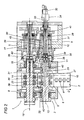
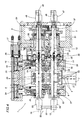
- figures 2, 3 and 4 are three schematic plan views showing three different embodiments of the unit in figure 1.
- Referring to figures 1 and 2 of the accompanying drawings, 1 denotes a feed unit serving to advance a
strip 2 of wrapping material along a direction denoted D and including a gumming device, denoted 3 in its entirety, by which anadhesive substance 4 is applied to the advancingstrip 2. Thereafter, thestrip 2 is taken up by a filter tip attachment and divided into single papers (not illustrated) by means of which to join filters (not illustrated) to relative cigarette sticks (not illustrated). - The
gumming device 3, mounted to relative support means consisting in a frame denoted 5, comprises afirst gumming roller 6 by which a layer of theadhesive 4 is applied to thestrip 2 at agumming station 7, and asecond transfer roller 8 operating in conjunction with thegumming roller 6, by which a given quantity ofadhesive 4 is released to thegumming roller 6 for application to thestrip 2. - Also forming part of the
gumming device 3 is acircuit 9 supplyingadhesive 4 continuously to the tworollers - The
gumming roller 6 is delimited outermost by acylindrical surface 10 revolving tangentially to the advancingstrip 2 at thegumming station 7, and cantilevered from thefree end 11 of arespective drive shaft 12 rotatable about ahorizontal axis 13 and carried by theframe 5. - The
gumming roller 6 is driven in rotation by theshaft 12 about therelative axis 13, turning in an anticlockwise direction as viewed in figure 1. - As indicated in figure 1, the
transfer roller 8 is delimited outermost by acylindrical surface 14 presenting depressions or pockets, denoted 15, and cantilevered from thefree end 16 of arespective drive shaft 17 carried together with theroller 8 by theframe 5. - The
roller 8 presents ahorizontal axis 18 lying parallel with and occupying the same substantially horizontal plane as theaxis 13 first mentioned. - With reference to figure 1, the
gumming roller 6 is set in rotation anticlockwise by theshaft 12 about therelative axis 13, through the agency of drive means not illustrated in the drawings, and thesame shaft 12 also causes thetransfer roller 8 to rotate together with therelative shaft 17 about theparallel axis 18 through the agency of further drive means, likewise not illustrated, turning clockwise as viewed in figure 1 and at a peripheral velocity identical to that of thegumming roller 6. - Again with reference to figure 1, the
transfer roller 8 is carried together with theshaft 17 on ayoke 19 hinged to theframe 5 by way of apivot 20 aligned on an axis parallel to theaxes frame 5 by anactuator 21 and thus cause thecylindrical surfaces area 22 of tangential contact coinciding with a common straight line generator extending parallel to theaxes trough 23 of substantially V-shaped cross-sectional profile between the tworollers - Still referring to figure 1, the
aforementioned circuit 9 supplying theadhesive 4 incorporates atank 24 with anoutlet pipeline 25 that terminates above thetrough 23, also avessel 26 positioned under therollers - The
vessel 26 connects with areturn pipeline 27 through which theadhesive 4 collected beneath the rollers is redirected back to thetank 24 by means of apump 28. - With reference to figure 2, the
gumming device 3 is equipped with acircuit 29 containing a fluid by means of which to control the temperature at thecylindrical surface 10 of thegumming roller 6. - In particular, the
circuit 29 is split into two portions, respectively afirst portion 30 and asecond portion 31. - The
first portion 30 extends through theshaft 12 supporting and driving thegumming roller 6, whilst thesecond portion 31 extends through theroller 6 itself. - The
circuit 29 communicates by way of thefirst portion 30 with aninlet duct 32 and with anoutlet duct 33, both rigidly associated with theframe 5 and connected to thefirst portion 30 by means of a hydraulic orpneumatic rotary coupling 34. - Also forming part of the
circuit 29 are quick coupler means 35 operating between thefree end 11 of theshaft 12 and therelative gumming roller 6, such as will allow theselfsame roller 6 to be separated from theshaft 12 at arelative coupling interface 36. - In particular, the
circuit 29 comprises aflow branch 37 extending along thefirst portion 30 and thesecond portion 31, internally of theroller 6. - A
first valve element 38 incorporated into thecircuit 29 operates along theflow branch 37 at thecoupling interface 36. - The
circuit 29 also comprises areturn branch 39 extending along thesecond portion 31 and along thefirst portion 30; similarly to theflow branch 37, thereturn branch 39 incorporates asecond valve element 40 operating at thecoupling interface 36. - More exactly, the
aforementioned flow branch 37 of thecircuit 29 departs from theinlet duct 32 and is composed of afirst duct 41, extending along thedrive shaft 12, also asecond duct 42 extending along thegumming roller 6 and incorporating a plurality ofannular chambers 43 formed within theroller 6. - The
first duct 41 and thesecond duct 42 are connected one to another at thecoupling interface 36 by thefirst valve element 38. - The
return branch 39 of thecircuit 29 departs from theannular chambers 43 and includes athird duct 44, extending along thegumming roller 6, also afourth duct 45 extending along thedrive shaft 12 and leading back ultimately to theoutlet duct 33. - The
third duct 44 and thefourth duct 45 are connected one to another at thecoupling interface 36 by thesecond valve element 40, which is similar to the first. - Whenever the
gumming roller 6 is detached from theend 11 of thedrive shaft 12 for the purposes of routine or major servicing, such as cleaning of theouter surface 10, the aforementioned first andsecond valve elements second portions circuit 29 at thecoupling interface 36. - In the example of figure 3, which illustrates the
transfer roller 8, this same roller is equipped likewise to advantage with acircuit 29 identical to that of thegumming roller 6, serving to control the temperature at the relativeouter surface 14. - Similarly, the
transfer roller 8 is provided with quick coupler means 35 operating between thefree end 16 of theshaft 17 and theroller 8, such as will allow theroller 8 to be separated from theshaft 17 at arelative coupling interface 36. - In the embodiment of figure 4, the
flow branch 37 of thecircuit 29 extends from aninlet duct 46, rigidly associated with theframe 5 and connected to theselfsame branch 37 by means of a hydraulic or pneumaticrotary coupling 47, passing through one of the two rollers, which preferably will be thegumming roller 6, whilst thereturn branch 39 passes through the remaining roller, and more exactly thetransfer roller 8, back to anoutlet duct 48 associated rigidly with theframe 5 and connected to theselfsame branch 39 by means of a hydraulic orpneumatic rotary coupling 49 identical to thecoupling 47 first mentioned. The two flow andreturn branches rollers - More exactly, the
flow branch 37 of thissecond circuit 29 departs from theinlet duct 46 and is composed of afirst duct 51, extending along thedrive shaft 12, also asecond duct 52 extending along thegumming roller 6 and incorporating a plurality ofannular chambers 53 formed within theroller 6. - The
first duct 51 and thesecond duct 52 are connected one to another at thecoupling interface 36 by thefirst valve element 38. - The
return branch 39 of thecircuit 29 departs from the aforementioned coupling means 50 and is composed of athird duct 54, extending along thetransfer roller 8 and incorporating a plurality ofannular chambers 55, also afourth duct 56 that extends along therelative drive shaft 17 and back ultimately to theoutlet duct 48. - The
third duct 54 and thefourth duct 56 are connected one to another at thecoupling interface 36 by thesecond valve element 40, which is similar to the first. - The aforementioned coupling means 50 comprise a
fixed duct 57 connected to the outlet of thesecond duct 52 and the inlet of thethird duct 54 by means of respectiverotary couplings - Likewise in this embodiment, whenever the
gumming roller 6 needs to be detached from theend 11 of theshaft 12 and thetransfer roller 8 from theend 16 of theshaft 17, for the purposes of routine or major servicing, typically cleaning, the aforementioned first andsecond valve elements second portions circuit 29 at thecoupling interface 36, isolating the first andsecond ducts gumming roller 6 and the third andfourth ducts transfer roller 8.
Claims (10)
- A feed unit (1) for strip wrapping material comprising a gumming device (3) acting on the strip (2), and means (5) by which to support the gumming device (3), wherein the gumming device (3) is composed of a gumming roller (6) and a transfer roller (8) rotatable about horizontal and parallel axes (13, 18), engaging one with another along an area (22) of tangential contact coinciding with a straight line generator common to the two rollers (6, 8) in such a way as to create a trough (23) between their respective cylindrical surfaces (10, 14), extending adjacent to the area (22) of tangential contact and serving to hold a predetermined quantity of an adhesive substance (4), characterized in that it comprises a circuit (29) through which to circulate a fluid controlling the temperature at least of the gumming roller (6) or of the transfer roller (8) of the gumming device (3).
- A unit as in claim 1, wherein the circuit (29) comprises a first portion (30) extending along a shaft (12; 17) carrying and driving the roller (6; 8), and a second portion (31) located internally of the roller (6; 8), of which the first portion (30) is connected to an inlet duct (32) and an outlet duct (33) admitting and releasing the fluid, the inlet and outlet ducts (32, 33) in their turn rigidly associated with the means (5) of support and connected to the circuit (29) by way of a hydraulic or pneumatic rotary coupling (34).
- A unit as in claim 2, comprising means (36) by which the free end (11; 16) of the drive shaft (12; 17) is coupled to the roller (6; 8) in such a way that the roller (6; 8) can be separated axially from the shaft (12; 17), also valve means (38, 40) operating on a flow branch (37) and on a return branch (39) of the circuit (29), associated with both the drive shaft (12; 17) and the respective roller (6; 8) and interposed between the first and second portions (30, 31) of the circuit in such a way as to allow of closing and opening the selfsame portions.
- A unit as in claims 1 to 3, wherein the roller (6; 8) is at least the gumming roller (6).
- A unit as in claims 1 to 3, comprising a circuit (29) associated with the gumming roller (6) and a circuit (29) associated with the transfer roller (8), through which to direct a fluid controlling the temperature of the two rollers (6; 8), each such circuit (29) connected to a respective inlet duct (32) and to a respective outlet duct (33) associated with the means (5) of support by way of a relative hydraulic or pneumatic rotary coupling (34).
- A unit as in claim 5, comprising means (36) by which both the free end (16) of one drive shaft (17) is coupled to the transfer roller (8) and the free end (11) of the remaining drive shaft (12) is coupled to the gumming roller (6), in such a way that both rollers (8, 6) can be separated axially from the respective shaft (17, 12), also valve means (40, 38) operating on a flow branch (37) and on a return branch (39) of each one of the two circuits (29), in such a way as to allow of closing and opening the first and second portions (30, 31) of the two circuits (29).
- A unit as in claims 1 to 6, wherein the flow branch (37) of the circuit (29) associated with each of the two rollers (6, 8) departs from the inlet duct (32) and passes through a first duct (41) extending along the drive shaft (12, 17), through a first valve element (38), then through a second duct (42) extending along the roller (6, 8) and comprising a plurality of annular chambers (43) formed within the roller (6, 8), whilst the return branch (39) departs from the annular chambers (43) and passes through a third duct (44) extending along the selfsame roller (6, 8), through a second valve element (40), then through a fourth duct (45) extending along the selfsame drive shaft (12, 17) and terminating at the outlet duct (33).
- A unit as in claim 1, comprising a circuit (29) through which to circulate a fluid controlling the temperature of both rollers (6, 8), of which a first flow branch (37) extends through one of the two rollers (6, 8) and through the respective drive shaft (12, 17), and the return branch (39) extends through the remaining roller (8, 6) and through the relative drive shaft (17, 12).
- A unit as in claim 8, wherein the circuit (29) comprises respective ducts (51, 52, 54, 56) and departs from an inlet duct (46) connected to the means (5) of support by way of a first rotary coupling (47), passing in sequence through the drive shaft (12, 17) of one of the two rollers (6, 8), through a first valve element (38), through a plurality of annular chambers (53, 55) located within one of the two rollers (6, 8), then through coupling means (50) interposed between the two rollers (6, 8), through a plurality of annular chambers (55, 53) located within the remaining roller (8, 6), through a second valve element (40), through the relative drive shaft (17, 12) and terminating at an outlet duct (48) connected to the means (5) of support by way of a second rotary coupling (49).
- A unit as in claim 9, wherein the coupling means (50) comprise a rotary coupling (58) connected to an outlet end of the flow branch (37) leaving one of the two rollers (6, 8), a rotary coupling (59) connected to an inlet end of the return branch (39) extending along the other roller (8, 6), and a fixed duct (57) interconnecting the two rotary couplings (58, 59).
Applications Claiming Priority (2)
| Application Number | Priority Date | Filing Date | Title |
|---|---|---|---|
| IT000450A ITBO20030450A1 (en) | 2003-07-29 | 2003-07-29 | POWER SUPPLY OF A TAPE OF WRAPPING MATERIAL. |
| ITBO20030450 | 2003-07-29 |
Publications (1)
| Publication Number | Publication Date |
|---|---|
| EP1563746A1 true EP1563746A1 (en) | 2005-08-17 |
Family
ID=34090504
Family Applications (1)
| Application Number | Title | Priority Date | Filing Date |
|---|---|---|---|
| EP04425507A Withdrawn EP1563746A1 (en) | 2003-07-29 | 2004-07-09 | A feed unit for strip wrapping material |
Country Status (5)
| Country | Link |
|---|---|
| US (1) | US7204883B2 (en) |
| EP (1) | EP1563746A1 (en) |
| JP (1) | JP2005046840A (en) |
| CN (1) | CN1576214A (en) |
| IT (1) | ITBO20030450A1 (en) |
Cited By (1)
| Publication number | Priority date | Publication date | Assignee | Title |
|---|---|---|---|---|
| ITBO20090178A1 (en) * | 2009-03-25 | 2010-09-26 | Gd Spa | TIRING DEVICE AND WHEELING METHOD OF A WRAPPING MATERIAL TAPE. |
Families Citing this family (10)
| Publication number | Priority date | Publication date | Assignee | Title |
|---|---|---|---|---|
| DE102005017391A1 (en) * | 2005-04-14 | 2006-10-19 | Hebenstreit Gmbh | Spreading head for waffle-sheet coating machines |
| DE102007039949B3 (en) * | 2007-08-23 | 2008-12-04 | Flooring Technologies Ltd. | Device for applying a suspension to a carrier plate |
| US8506709B2 (en) | 2010-04-02 | 2013-08-13 | Advenira Enterprises, Inc. | Roll coater having a recirculation loop for treating excess fluid |
| US10195638B2 (en) * | 2013-10-30 | 2019-02-05 | Samsung Sdi Co., Ltd. | Apparatus for coating a separator having collection chamber and method for coating the separator |
| KR20150106812A (en) * | 2013-10-30 | 2015-09-22 | 삼성에스디아이 주식회사 | Apparatus and method for coating a separator |
| GB201509080D0 (en) | 2015-05-27 | 2015-07-08 | Landa Labs 2012 Ltd | Coating apparatus |
| CN105107689B (en) * | 2015-09-18 | 2017-08-15 | 广东中科天工智能技术有限公司 | Full-automatic glue circulating system and method |
| EP3851210B1 (en) * | 2020-01-14 | 2025-12-24 | Jesús Francisco Barberan Latorre | Applicator roller |
| CN113909049B (en) * | 2021-10-19 | 2023-02-17 | 一汽解放汽车有限公司 | oiling device |
| CN115122718B (en) * | 2022-06-30 | 2023-11-17 | 红豆集团无锡红豆童装有限公司 | Light and thin mosquito-proof auxiliary agent fabric for children and preparation process thereof |
Citations (5)
| Publication number | Priority date | Publication date | Assignee | Title |
|---|---|---|---|---|
| US3788271A (en) * | 1972-04-14 | 1974-01-29 | Perma Glas Mesh Corp | Apparatus for applying pressure sensitive adhesive to glass fiber mesh material |
| EP0791401A1 (en) * | 1995-09-07 | 1997-08-27 | AZIONARIA COSTRUZIONI MACCHINE AUTOMATICHE-A.C.M.A.-S.p.A. | Gumming device |
| US6258168B1 (en) * | 1998-08-06 | 2001-07-10 | Hauni Maschinenbau Ag | Apparatus for applying adhesive to a web-shaped carrier |
| DE10019930A1 (en) * | 2000-04-20 | 2001-10-25 | Hauni Maschinenbau Ag | Glue-applicator for smokers' products incorporates applicator nozzle, rotary roller valve, feeder pipe, and chamber housing and irregularities in peripheral surface |
| US6358318B1 (en) * | 1997-10-14 | 2002-03-19 | G.D S.P.A. | Gumming device |
Family Cites Families (3)
| Publication number | Priority date | Publication date | Assignee | Title |
|---|---|---|---|---|
| DE3439090C2 (en) * | 1984-10-25 | 1987-01-08 | Albert-Frankenthal Ag, 6710 Frankenthal | Cylinders for web material processing machines |
| DE19939073A1 (en) * | 1999-08-18 | 2001-02-22 | Beiersdorf Ag | Process for the continuous, solvent and mastication-free production of pressure-sensitive self-adhesive compositions based on non-thermoplastic elastomers and their coating for the production of self-adhesive articles |
| EP1731045B1 (en) * | 2000-04-20 | 2011-02-23 | Hauni Maschinenbau AG | Device for gluing a wrapping material on a rod-shaped article in the tobacco industry |
-
2003
- 2003-07-29 IT IT000450A patent/ITBO20030450A1/en unknown
-
2004
- 2004-07-09 EP EP04425507A patent/EP1563746A1/en not_active Withdrawn
- 2004-07-22 JP JP2004214660A patent/JP2005046840A/en not_active Withdrawn
- 2004-07-29 US US10/901,193 patent/US7204883B2/en not_active Expired - Fee Related
- 2004-07-29 CN CN200410055736.5A patent/CN1576214A/en active Pending
Patent Citations (5)
| Publication number | Priority date | Publication date | Assignee | Title |
|---|---|---|---|---|
| US3788271A (en) * | 1972-04-14 | 1974-01-29 | Perma Glas Mesh Corp | Apparatus for applying pressure sensitive adhesive to glass fiber mesh material |
| EP0791401A1 (en) * | 1995-09-07 | 1997-08-27 | AZIONARIA COSTRUZIONI MACCHINE AUTOMATICHE-A.C.M.A.-S.p.A. | Gumming device |
| US6358318B1 (en) * | 1997-10-14 | 2002-03-19 | G.D S.P.A. | Gumming device |
| US6258168B1 (en) * | 1998-08-06 | 2001-07-10 | Hauni Maschinenbau Ag | Apparatus for applying adhesive to a web-shaped carrier |
| DE10019930A1 (en) * | 2000-04-20 | 2001-10-25 | Hauni Maschinenbau Ag | Glue-applicator for smokers' products incorporates applicator nozzle, rotary roller valve, feeder pipe, and chamber housing and irregularities in peripheral surface |
Cited By (3)
| Publication number | Priority date | Publication date | Assignee | Title |
|---|---|---|---|---|
| ITBO20090178A1 (en) * | 2009-03-25 | 2010-09-26 | Gd Spa | TIRING DEVICE AND WHEELING METHOD OF A WRAPPING MATERIAL TAPE. |
| EP2233018A1 (en) * | 2009-03-25 | 2010-09-29 | G.D S.p.A. | A gumming device and a method for gumming a web of wrapping material |
| US7976656B2 (en) | 2009-03-25 | 2011-07-12 | G.D.S.P.A. | Gumming device and a method for gumming a web of wrapping material |
Also Published As
| Publication number | Publication date |
|---|---|
| US7204883B2 (en) | 2007-04-17 |
| CN1576214A (en) | 2005-02-09 |
| JP2005046840A (en) | 2005-02-24 |
| ITBO20030450A1 (en) | 2005-01-30 |
| US20050022730A1 (en) | 2005-02-03 |
Similar Documents
| Publication | Publication Date | Title |
|---|---|---|
| US7204883B2 (en) | Feed unit for strip wrapping material | |
| JP3798298B2 (en) | Rotating device, method for conveying worn article, and method for conveying web | |
| CN101844122B (en) | Gumming device and method for gumming web of wrapping material | |
| CN101559417B (en) | Application of glue to strips of material for the tobacco processing industry | |
| US3476631A (en) | Method of and means for distributing glue to a moving web | |
| CN105127062B (en) | The sizing of the material strips of the tobacco industry | |
| AU709283B2 (en) | Improved low pressure single facer | |
| JP5022808B2 (en) | Sheet joining apparatus and manufacturing method of absorbent article | |
| GB2260749A (en) | Packet banding device | |
| MX2008015874A (en) | An apparatus and method for forming air-laid absorbent cores. | |
| EP1798013A1 (en) | Glue distributing apparatus | |
| CN102687905A (en) | Method for applying glue to a filter wrapper strip in a filter rod machine and use of a glue application device for such a method | |
| US5766121A (en) | Method and device for making packets from packaging sheets, especially for cigarettes or the like | |
| JPH05140808A (en) | Apparatus for binding sheet-shaped fibrous structure | |
| GB2092427A (en) | Method and apparatus for joining coaxial rod shaped articles | |
| CN214440475U (en) | Cigarette tipping paper regional synchronous gluing device | |
| US5666869A (en) | Tip paper cutting apparatus for a filter cigarette manufacturing system | |
| US1986039A (en) | Adhesive-applying mechanism | |
| CN104709498B (en) | Full-evacuation and half-evacuation device for cigarette packing machine | |
| ITBO970610A1 (en) | GUMMATOR DEVICE. | |
| US4111740A (en) | Apparatus for joining axially abutting rods of the cigarette industry | |
| JPH1086916A (en) | Apparatus for joining a tear release strip to a film web | |
| KR0175525B1 (en) | Sanitary article manufacturing equipment | |
| CN112354788B (en) | A device for synchronous gluing of cigarette tipping paper in different areas | |
| US2557011A (en) | Corrugating roll lubricator |
Legal Events
| Date | Code | Title | Description |
|---|---|---|---|
| PUAI | Public reference made under article 153(3) epc to a published international application that has entered the european phase |
Free format text: ORIGINAL CODE: 0009012 |
|
| AK | Designated contracting states |
Kind code of ref document: A1 Designated state(s): AT BE BG CH CY CZ DE DK EE ES FI FR GB GR HU IE IT LI LU MC NL PL PT RO SE SI SK TR |
|
| AX | Request for extension of the european patent |
Extension state: AL HR LT LV MK |
|
| 17P | Request for examination filed |
Effective date: 20050919 |
|
| AKX | Designation fees paid |
Designated state(s): AT BE BG CH CY CZ DE DK EE ES FI FR GB GR HU IE IT LI LU MC NL PL PT RO SE SI SK TR |
|
| 17Q | First examination report despatched |
Effective date: 20060324 |
|
| GRAP | Despatch of communication of intention to grant a patent |
Free format text: ORIGINAL CODE: EPIDOSNIGR1 |
|
| STAA | Information on the status of an ep patent application or granted ep patent |
Free format text: STATUS: THE APPLICATION IS DEEMED TO BE WITHDRAWN |
|
| 18D | Application deemed to be withdrawn |
Effective date: 20070919 |