EP1562352A1 - Mobile phone with buffer - Google Patents
Mobile phone with buffer Download PDFInfo
- Publication number
- EP1562352A1 EP1562352A1 EP05002037A EP05002037A EP1562352A1 EP 1562352 A1 EP1562352 A1 EP 1562352A1 EP 05002037 A EP05002037 A EP 05002037A EP 05002037 A EP05002037 A EP 05002037A EP 1562352 A1 EP1562352 A1 EP 1562352A1
- Authority
- EP
- European Patent Office
- Prior art keywords
- casing
- buffer members
- terminal device
- communication terminal
- mobile communication
- Prior art date
- Legal status (The legal status is an assumption and is not a legal conclusion. Google has not performed a legal analysis and makes no representation as to the accuracy of the status listed.)
- Ceased
Links
- 238000010295 mobile communication Methods 0.000 claims description 20
- 230000008878 coupling Effects 0.000 claims description 2
- 238000010168 coupling process Methods 0.000 claims description 2
- 238000005859 coupling reaction Methods 0.000 claims description 2
- 238000010276 construction Methods 0.000 description 1
- 238000005034 decoration Methods 0.000 description 1
- 239000013013 elastic material Substances 0.000 description 1
- 238000012986 modification Methods 0.000 description 1
- 230000004048 modification Effects 0.000 description 1
- 239000011347 resin Substances 0.000 description 1
- 229920005989 resin Polymers 0.000 description 1
Images







Classifications
-
- H—ELECTRICITY
- H04—ELECTRIC COMMUNICATION TECHNIQUE
- H04M—TELEPHONIC COMMUNICATION
- H04M1/00—Substation equipment, e.g. for use by subscribers
- H04M1/02—Constructional features of telephone sets
- H04M1/0202—Portable telephone sets, e.g. cordless phones, mobile phones or bar type handsets
- H04M1/0206—Portable telephones comprising a plurality of mechanically joined movable body parts, e.g. hinged housings
- H04M1/0208—Portable telephones comprising a plurality of mechanically joined movable body parts, e.g. hinged housings characterized by the relative motions of the body parts
- H04M1/021—Portable telephones comprising a plurality of mechanically joined movable body parts, e.g. hinged housings characterized by the relative motions of the body parts using combined folding and rotation motions
Definitions
- the present invention relates to a mobile communication terminal device, in particular, a device in which two casings are foldably connected to each other by means of a hinge.
- a mobile phone 100 has a first casing 104 and a second casing 102, which are connected by a hinge 105.
- the casings rotate around a hinge axis 105a to be thereby folded.
- the first casing 104 has a display portion 103
- the second casing 102 has a key input portion 101.
- two buffer members 106 formed of elastic material.
- JP 11-275191 A discloses the above construction.
- JP 2003-330590 A discloses a mobile phone having a two-axis hinge.
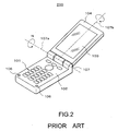
- a mobile phone 200 has a two-axis hinge 107 with a first axis 107a and a second axis 107b.
- the hinge 107 connects the first casing 104 and the second casing 102 to each other.
- the first casing 104 rotates around the hinge axis 107a, and can be folded. Further, the first casing 104 can rotate around the hinge axis 107b.
- the display portion 103 can be situated on the outer side of the mobile phone, or conversely, on the inner side of the mobile phone. Also in the mobile phone with the two-axis hinge, the buffer members 106 effectively prevent the first and second casings from colliding with each other.
- FIG. 3 is a sectional view of the mobile phone 200 in the folded state, showing the portion where the buffer members 106 are arranged.
- a force causing rotation of the first casing around the hinge axis 107b may be applied.
- the buffer members 106 can prevent the first and second casings from coming into contact with each other.
- FIG. 4 is a sectional view of the same mobile phone 200 in the folded state, showing the region in the vicinity of the hinge portion. No buffer members are arranged in this region. Thus, even a slight rotation of the first casing can result its collision with the second casing, thereby damaging the display portion 103.
- a mobile communication terminal device includes a first casing and a second casing.
- the terminal is equipped with a multi-axis hinge portion rotatably connecting the two casings, andbuffermembers adapted to be situatedbetween the two casings when they are folded together.
- the buffer members are positioned in the region of the casing surface in the vicinity of the multi-axis hinge portion and in the region of the casing surface on the side opposite to the multi-axis hinge portion.
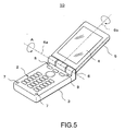
- a two-axis hinge 6 couples a first casing 5 and a second casing 3 to each other.
- the first casing 5 has a display portion 4.
- the second casing 3 has a key input portion 2.
- the second casing 3 has buffer members 7 and 8 in the regions in the vicinity of its four corner portions.
- the buffer members 7 are arranged in the region of the second casing 3 on the side opposite to the two-axis hinge 6.
- the buffer members 8 are arranged in the region on the surface of the second casing 3 in the vicinity of the two-axis hinge 6.
- the first and second casings can rotate around a hinge axis 6a to be thereby folded.
- the first casing 5 can rotate around a hinge axis 6b.
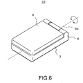
- the first and second casings can be folded such that the display portion 4 is situated on the inner side of the mobile phone as shown in FIG. 6, or can be folded such that the display portion 4 is situated on the outer side of the mobile phone as shown in FIG. 7.
- the four buffer members 7 and 8 arranged on the second casing secure a clearance between the first and second casings.
- the buffer members 8 are arranged in the region in the vicinity of the two-axis hinge portion 6. A torque around the hinge axis 6b may be applied to the first casing 5 in the folded state. Even in such a case, due to the presence of the buffer members 8, the region of the first casing 5 in the vicinity of the two-axis hinge 6 does not easily rotate. Thus, it is possible to prevent the casings from coming into contact with each other.
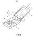
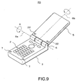
- FIG. 8 and FIG. 9 show another example of a mobile phone, indicated generally by reference numeral 20.
- the two-axis hinge 6 couples the first casing 5 and the second casing 3 to each other.
- the buffer members 7 are arranged in the region of the second casing 3 on the side opposite to the two-axis hinge 6.
- Other buffer members 21, however, are arranged in the region of the first casing 5 in the vicinity of the two-axis hinge 6.
- buffer members 22 are arranged in the region of the other surface of the first casing 5 in the vicinity of the two-axis hinge 6.
- the buffer members 7 and 21 prevent the two casings from coming into contact with each other.
- the buffer members 7 and 22 prevent the two casings from coming into contact with each other. Due to the buffer members 21 and 22, the region of the first casing 5 in the vicinity of the two-axis hinge 6 does not easily move or rotate.
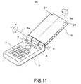
- FIG. 10 and FIG. 11 show still another example of a mobile phone, generally indicated by reference numeral 30.
- the buffer members 8 are arranged in the region of the second casing 3 in the vicinity of the two-axis hinge 6.
- buffer members 23 are arranged in the region of the first casing 5 on the side opposite to the two-axis hinge 6.
- buffer members 24 are arranged in the region thereof on the side opposite to the two-axis hinge 6.
- the positions of the buffer members between the casings when the two casings are folded are the same as those in the example shown in FIGS. 8 and 9. Also in this example, the casings are prevented from coming into contact with each other.
- FIG. 12 and FIG. 13 show still another example of a mobile phone, generally indicated by reference numeral 40.
- all the buffer members are arranged on the first casing 5.
- buffer members 25 are arranged on the surface of the first casing 5 where the display portion 4 is arranged.
- the buffer members 25 are arranged in the region in the vicinity of the two-axis hinge 6 and in the region on the side opposite to the two-axis hinge 6.
- buffer members 26 are arranged on the surface reverse to the above-described surface.
- the buffer members 26 are arranged in the region in the vicinity of the two-axis hinge 6 and in the region on the side opposite to the two-axis hinge 6.
- the positions of the buffer members when the mobile phone is folded are the same as those in the above example.
- the two casings in the folded state are prevented from coming into contact with each other.
- the buffer members it is not absolutely necessary for the buffer members to be arranged symmetrically with respect to the hinge axis 6b. As long as the buffer members can effectively prevent the two casings from coming into contact with each other, it is not necessary for the buffer members to be arranged symmetrically with respect to the hinge axis 6b. In the region of the casing in the vicinity of the two-axis hinge and in the region on the side opposite thereto, three or more buffer members can be arranged, respectively.
- FIG. 14 shows still another example of a mobile phone, generally indicated by reference numeral 50.
- a buffer member 27 is arranged in the region of the second casing 3 on the side opposite to the two-axis hinge 6.
- the buffer member 27 is a single continuous member arranged so as to extend from a position in the vicinity of one end portion of the second casing 3 to a position in the vicinity of the other end portion thereof.
- a buffer member 28 is also arranged so as to extend from a position in the vicinity of one end portion of the casing to a position in the vicinity of the other end portion thereof.
- the buffer members 27 and 28 thus arranged can effectively prevent the two casings 3 and 5 from coming into contact with each other when they are folded. Further, the buffer members 27 and 28 prevent the casings from coming into contact with each other when a torque around the hinge axis 6b is applied.
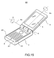
- FIG. 15 shows still another example of a mobile phone, generally indicated by reference numeral 60.
- Buffer members 29 and 30 are respectively arranged in the vicinity of the side surfaces of the second casing 3.
- each of the buffer members 29 and 30 is a single continuous member arranged so as to extend from the region of the second casing 3 in the vicinity of the two-axis hinge 6 to the region on the side opposite thereto.
- the buffer members 29 and 30 thus arranged can effectively prevent the two casings 3 and 5 from coming into contact with each other when they are folded.
- the buffer members 29 and 30 prevent the casings from coming into contact with each other when a torque around the hinge axis 6b is applied.
- All the buffer members shown in FIG. 14 and FIG. 15 can be arranged on the first casing 5.
- the buffer members are arranged on both sides of the first casing 5. It is possible to arrange buffer members as those shown in FIG. 14 on one surface of the first casing, and to arrange buffer members as those shown in FIG. 15 on the other surface thereof.
- the buffer members 27 and 28 shown in FIG. 14 one may be arranged on the first casing, and the other may be arranged on the second casing.
- the buffer members arranged on the first casing are arranged on both sides of the first casing.
- the buffer members can be arranged substantially in the entire region of the surface of the first or second casing in the vicinity of the outer periphery thereof. Accordingly, the buffer member can have a ring-like or a rectangle-like configuration.
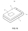
- FIG. 16 shows still another example of a mobile phone, generally indicated by reference numeral 70, which has a relatively small display portion 41 on the reverse surface (the surface on the side opposite to the surface where the large display portion 4 is arranged) of the first casing 5.
- the display portion 41 can be utilized.
- the buffer members may be formed of elastic resin or the like.
- the present invention is also applicable to other mobile information terminal devices, such as a personal handy phone system or a personal digital assistant.
- the hinge for coupling the two casings it is possible to use a multi-axis hinge having three or more rotation axes.
Landscapes
- Engineering & Computer Science (AREA)
- Signal Processing (AREA)
- Telephone Set Structure (AREA)
- Casings For Electric Apparatus (AREA)
Abstract
Description
- The present invention relates to a mobile communication terminal device, in particular, a device in which two casings are foldably connected to each other by means of a hinge.
- Recently, many mobile phones have a structure in which two casings are connected to each other by a hinge. The two casings rotate around the hinge axis and are thereby folded. Referring to FIG. 1, a
mobile phone 100 has afirst casing 104 and asecond casing 102, which are connected by ahinge 105. The casings rotate around ahinge axis 105a to be thereby folded. Thefirst casing 104 has adisplay portion 103, and thesecond casing 102 has akey input portion 101. In the region of the upper surface of thesecond casing 102 which is on the side opposite to thehinge 105, there are provided twobuffer members 106 formed of elastic material. Thus, when themobile phone 100 is folded, the first and second casings do not directly collide with each other. Thus, it is possible to prevent the surfaces of the casings, in particular, thedisplay portion 103, from being damaged. JP 11-275191 A discloses the above construction. - Apart from this, a mobile phone has come into widespread use in which the first and second casings are connected by a two-axis hinge. The two-axis hinge allows the two casings to make more diversified movements with respect to each other. JP 2003-330590 A discloses a mobile phone having a two-axis hinge. As shown in FIG. 2, a
mobile phone 200 has a two-axis hinge 107 with a first axis 107a and asecond axis 107b. Thehinge 107 connects thefirst casing 104 and thesecond casing 102 to each other. Thefirst casing 104 rotates around the hinge axis 107a, and can be folded. Further, thefirst casing 104 can rotate around thehinge axis 107b. Thus, when thefirst casing 104 is folded, thedisplay portion 103 can be situated on the outer side of the mobile phone, or conversely, on the inner side of the mobile phone. Also in the mobile phone with the two-axis hinge, thebuffer members 106 effectively prevent the first and second casings from colliding with each other. - However, the mobile phone with the two-axis hinge involves a problem as described below. FIG. 3 is a sectional view of the
mobile phone 200 in the folded state, showing the portion where thebuffer members 106 are arranged. In this state, a force causing rotation of the first casing around thehinge axis 107b (in the direction as indicated by the arrow in FIG. 3) may be applied. In such a case, thebuffer members 106 can prevent the first and second casings from coming into contact with each other. FIG. 4 is a sectional view of the samemobile phone 200 in the folded state, showing the region in the vicinity of the hinge portion. No buffer members are arranged in this region. Thus, even a slight rotation of the first casing can result its collision with the second casing, thereby damaging thedisplay portion 103. - The present invention has been made with a view toward solving the above problem in the prior art. A mobile communication terminal device according to the present invention includes a first casing and a second casing. The terminal is equipped with a multi-axis hinge portion rotatably connecting the two casings, andbuffermembers adapted to be situatedbetween the two casings when they are folded together. The buffer members are positioned in the region of the casing surface in the vicinity of the multi-axis hinge portion and in the region of the casing surface on the side opposite to the multi-axis hinge portion. In this terminal device, a clearance is secured between the casings when the two casings are folded together, so that there is no fear of the casings coming into contact with each other to damage the display portion, etc.
- The above and other objects, features and advantages of the present invention will become apparent from the following detailed description when taken with the accompanying drawings in which:
- FIG. 1 is a perspective view of a conventional mobile phone having a one-axis hinge;
- FIG. 2 is a perspective view of a conventional mobile phone having a two-axis hinge;
- FIG. 3 is a sectional view of a conventional mobile phone, showing the portion thereof where buffer members are arranged;
- FIG. 4 is a sectional view of the conventional mobile phone, showing the portion thereof in the vicinity of the hinge;
- FIG. 5 is a perspective view of an example of a mobile phone of the present invention in a state in which two casings are opened;
- FIG. 6 is a perspective view of an example of the mobile phone of the present invention in a state in which the casings are folded;
- FIG. 7 is a perspective view of an example of the mobile phone of the present invention in a state in which the casings are folded with one casing upside down;
- FIG. 8 is a perspective view of another example of the mobile phone of the present invention in a state in which the two casings are opened;
- FIG. 9 is a perspective view of still another example of the mobile phone of the present invention in a state in which the two casings are opened;
- FIG. 10 is a perspective view of still another example of the mobile phone of the present invention in a state in which the two casings are opened;
- FIG. 11 is a perspective view of still another example of the mobile phone of the present invention in a state in which the two casings are opened;
- FIG. 12 is a perspective view of still another example of the mobile phone of the present invention in a state in which the two casings are opened;
- FIG. 13 is a perspective view of still another example of the mobile phone of the present invention in a state in which the two casings are opened;
- FIG. 14 is a perspective view of still another example of the mobile phone of the present invention in a state in which the two casings are opened;
- FIG. 15 is a perspective view of still another example of the mobile phone of the present invention in a state in which the two casings are opened; and
- FIG. 16 is a perspective view of still another example of the mobile phone of the present invention.
-
- In the following, a mobile phone will be described as an example of a mobile communication terminal device according to the present invention. Referring to FIG. 5, a two-
axis hinge 6 couples afirst casing 5 and asecond casing 3 to each other. Thefirst casing 5 has adisplay portion 4. Thesecond casing 3 has akey input portion 2. Further, thesecond casing 3 hasbuffer members buffer members 7 are arranged in the region of thesecond casing 3 on the side opposite to the two-axis hinge 6. Thebuffer members 8 are arranged in the region on the surface of thesecond casing 3 in the vicinity of the two-axis hinge 6. The first and second casings can rotate around ahinge axis 6a to be thereby folded. Thefirst casing 5 can rotate around ahinge axis 6b. Thus, the first and second casings can be folded such that thedisplay portion 4 is situated on the inner side of the mobile phone as shown in FIG. 6, or can be folded such that thedisplay portion 4 is situated on the outer side of the mobile phone as shown in FIG. 7. As shown in FIG. 7, when the mobile phone is folded, the fourbuffer members buffer members 8 are arranged in the region in the vicinity of the two-axis hinge portion 6. A torque around thehinge axis 6b may be applied to thefirst casing 5 in the folded state. Even in such a case, due to the presence of thebuffer members 8, the region of thefirst casing 5 in the vicinity of the two-axis hinge 6 does not easily rotate. Thus, it is possible to prevent the casings from coming into contact with each other. - FIG. 8 and FIG. 9 show another example of a mobile phone, indicated generally by
reference numeral 20. Also in this example, the two-axis hinge 6 couples thefirst casing 5 and thesecond casing 3 to each other. In this example, thebuffer members 7 are arranged in the region of thesecond casing 3 on the side opposite to the two-axis hinge 6.Other buffer members 21, however, are arranged in the region of thefirst casing 5 in the vicinity of the two-axis hinge 6. Further, as shown in FIG. 9,buffer members 22 are arranged in the region of the other surface of thefirst casing 5 in the vicinity of the two-axis hinge 6. When themobile phone 20 is folded, with thedisplay portion 4 being situated on the inner side of themobile phone 20, thebuffer members mobile phone 20 is folded, with thedisplay portion 4 being situated on the outer side of themobile phone 20, thebuffer members buffer members first casing 5 in the vicinity of the two-axis hinge 6 does not easily move or rotate. - FIG. 10 and FIG. 11 show still another example of a mobile phone, generally indicated by
reference numeral 30. In this example, thebuffer members 8 are arranged in the region of thesecond casing 3 in the vicinity of the two-axis hinge 6. At the same time,buffer members 23 are arranged in the region of thefirst casing 5 on the side opposite to the two-axis hinge 6. As shown in FIG. 11, also on the surface of thefirst casing 5 reverse to thedisplay portion 4,buffer members 24 are arranged in the region thereof on the side opposite to the two-axis hinge 6. In this example, the positions of the buffer members between the casings when the two casings are folded are the same as those in the example shown in FIGS. 8 and 9. Also in this example, the casings are prevented from coming into contact with each other. - FIG. 12 and FIG. 13 show still another example of a mobile phone, generally indicated by
reference numeral 40. In this example, all the buffer members are arranged on thefirst casing 5. As shown in FIG. 12,buffer members 25 are arranged on the surface of thefirst casing 5 where thedisplay portion 4 is arranged. Thebuffer members 25 are arranged in the region in the vicinity of the two-axis hinge 6 and in the region on the side opposite to the two-axis hinge 6. Further, as shown in FIG. 13,buffer members 26 are arranged on the surface reverse to the above-described surface. Like thebuffer members 25, thebuffer members 26 are arranged in the region in the vicinity of the two-axis hinge 6 and in the region on the side opposite to the two-axis hinge 6. In this example, the positions of the buffer members when the mobile phone is folded are the same as those in the above example. Also in this example, the two casings in the folded state are prevented from coming into contact with each other. - In the above example, it is not absolutely necessary for the buffer members to be arranged symmetrically with respect to the
hinge axis 6b. As long as the buffer members can effectively prevent the two casings from coming into contact with each other, it is not necessary for the buffer members to be arranged symmetrically with respect to thehinge axis 6b. In the region of the casing in the vicinity of the two-axis hinge and in the region on the side opposite thereto, three or more buffer members can be arranged, respectively. - FIG. 14 shows still another example of a mobile phone, generally indicated by
reference numeral 50. Abuffer member 27 is arranged in the region of thesecond casing 3 on the side opposite to the two-axis hinge 6. Thebuffer member 27 is a single continuous member arranged so as to extend from a position in the vicinity of one end portion of thesecond casing 3 to a position in the vicinity of the other end portion thereof. Further, in the region of thesecond casing 3 in the vicinity of the two-axis hinge 6, abuffer member 28 is also arranged so as to extend from a position in the vicinity of one end portion of the casing to a position in the vicinity of the other end portion thereof. Thebuffer members casings buffer members hinge axis 6b is applied. - FIG. 15 shows still another example of a mobile phone, generally indicated by
reference numeral 60.Buffer members second casing 3. As in the above example, each of thebuffer members second casing 3 in the vicinity of the two-axis hinge 6 to the region on the side opposite thereto. Thebuffer members casings buffer members hinge axis 6b is applied. - All the buffer members shown in FIG. 14 and FIG. 15 can be arranged on the
first casing 5. In this case, the buffer members are arranged on both sides of thefirst casing 5. It is possible to arrange buffer members as those shown in FIG. 14 on one surface of the first casing, and to arrange buffer members as those shown in FIG. 15 on the other surface thereof. Of thebuffer members - FIG. 16 shows still another example of a mobile phone, generally indicated by
reference numeral 70, which has a relativelysmall display portion 41 on the reverse surface (the surface on the side opposite to the surface where thelarge display portion 4 is arranged) of thefirst casing 5. In the state in which the two casings are folded so that thedisplay portion 4 is situated on the inner side, thedisplay portion 41 can be utilized. - Various decorations, such as various patterns, pictures, or relieves, can be formed on the buffer members. The buffer members may be formed of elastic resin or the like. Apart from a mobile phone, the present invention is also applicable to other mobile information terminal devices, such as a personal handy phone system or a personal digital assistant. As the hinge for coupling the two casings, it is possible to use a multi-axis hinge having three or more rotation axes.
- While the present invention has been described in connection with certain preferred embodiments, it is to be understood that the subject matter encompassed by the present invention is not limited to those specific embodiments. On the contrary, it is intended to include all alternatives, modifications, and equivalents as can be included within the spirit and scope of the following claims.
Claims (16)
- A mobile communication terminal device equipped with a first casing and a second casing, comprising:wherein the buffer members are positioned in a casing region in the vicinity of the multi-axis hinge portion and in a casing region on a side opposite to the multi-axis hinge portion.a multi-axis hinge portion rotatably coupling the first and second casings; andbuffer members that are arranged between the first and second casings when the first and second casings are folded,
- A mobile communication terminal device according to Claim 1, wherein all the buffer members are arranged on the first casing.
- A mobile communication terminal device according to Claim 1, wherein all the buffer members are arranged on the second casing.
- A mobile communication terminal device according to Claim 1, wherein the buffer members are arranged in a region of the first casing in the vicinity of the multi-axis hinge portion and in a region of the second casing on the side opposite to the multi-axis hinge portion.
- A mobile communication terminal device according to Claim 1, wherein the buffer members are arranged in a region of the second casing in the vicinity of the multi-axis hinge portion and in a region of the first casing on the side opposite to the multi-axis hinge portion.
- A mobile communication terminal device according to Claim 1, wherein the first casing comprises a display portion,
wherein the second casing comprises a key input portion, and
wherein the buffer members are arranged on two main surfaces of the first casing. - A mobile communication terminal device according to Claim 1, wherein the first casing comprises a display portion,
wherein the second casing comprises a key input portion, and
wherein the buffer members are arranged on the surface of the second casing on which the key input portion is arranged. - A mobile communication terminal device according to Claim 6, wherein the first casing has a large display portion on one surface thereof and a small display portion on the other surface thereof.
- A mobile communication terminal device according to Claim 1, wherein, in the casing region, the buffer members are arranged on both sides of a central axis of the casing.
- A mobile communication terminal device according to Claim 9, wherein the buffer members have a dot-like configuration.
- A mobile communication terminal device according to Claim 1, wherein, in the casing regions, the buffer members are arranged such that the buffer members extend from a position in the vicinity of one side surface of the casing to a position in the vicinity of the other side surface of the casing.
- A mobile communication terminal device according to Claim 1, wherein the buffer members are arranged in the vicinity of both side surfaces of the casing and extends from a position in the vicinity of the multi-axis hinge portion to a position on the side opposite thereto, with their end portions being situated in the casing regions.
- A mobile communication terminal device according to Claim 1, wherein the buffer members are arranged substantially in the entire region in the vicinity of the outer periphery of the second casing.
- A mobile communication terminal device according to Claim 1, wherein the buffer members are arranged substantially in the entire regions in the vicinity of the outer periphery of two main surfaces of the first casing.
- A mobile communication terminal device according to any of Claims 1 to 14, wherein the buffer members are elastic members.
- A mobile communication terminal device according to any of Claims 1 to 15, wherein the mobile communication terminal device is a mobile phone.
Applications Claiming Priority (2)
| Application Number | Priority Date | Filing Date | Title |
|---|---|---|---|
| JP2004030841A JP4102768B2 (en) | 2004-02-06 | 2004-02-06 | Portable information terminal device |
| JP2004030841 | 2004-02-06 |
Publications (1)
| Publication Number | Publication Date |
|---|---|
| EP1562352A1 true EP1562352A1 (en) | 2005-08-10 |
Family
ID=34675561
Family Applications (1)
| Application Number | Title | Priority Date | Filing Date |
|---|---|---|---|
| EP05002037A Ceased EP1562352A1 (en) | 2004-02-06 | 2005-02-01 | Mobile phone with buffer |
Country Status (4)
| Country | Link |
|---|---|
| US (1) | US20050176478A1 (en) |
| EP (1) | EP1562352A1 (en) |
| JP (1) | JP4102768B2 (en) |
| CN (1) | CN1652548A (en) |
Families Citing this family (7)
| Publication number | Priority date | Publication date | Assignee | Title |
|---|---|---|---|---|
| EP1486688A4 (en) * | 2002-03-19 | 2010-09-22 | Panasonic Corp | JOINT, PORTABLE TERMINAL TYPE A OPENING / CLOSING HAVING SUCH ARTICULATION |
| JP4563909B2 (en) * | 2005-09-29 | 2010-10-20 | 京セラ株式会社 | Mobile terminal device |
| WO2008129646A1 (en) * | 2007-04-13 | 2008-10-30 | Fujitsu Limited | Electronic apparatus |
| JP5169426B2 (en) * | 2008-04-17 | 2013-03-27 | Necカシオモバイルコミュニケーションズ株式会社 | Foldable electronics |
| USD617321S1 (en) * | 2009-02-05 | 2010-06-08 | Nokia Corporation | Handset |
| JP2010022070A (en) * | 2009-10-28 | 2010-01-28 | Kyocera Corp | Mobile terminal device |
| KR20120013703A (en) * | 2010-08-06 | 2012-02-15 | 삼성전자주식회사 | Handheld terminal |
Citations (4)
| Publication number | Priority date | Publication date | Assignee | Title |
|---|---|---|---|---|
| US20020128053A1 (en) * | 2001-03-08 | 2002-09-12 | Lg Electronics Inc. | Mobile terminal |
| EP1339203A2 (en) * | 2002-02-25 | 2003-08-27 | Omron Corporation | Rotary structure for relaying signals |
| WO2003075475A1 (en) * | 2002-03-02 | 2003-09-12 | M2Sys Co., Ltd. | Rotary hinge mechanism of portable phone |
| US20030228847A1 (en) * | 2002-06-11 | 2003-12-11 | Mitsuyoshi Matsumoto | Portable communication device |
Family Cites Families (4)
| Publication number | Priority date | Publication date | Assignee | Title |
|---|---|---|---|---|
| SE516510C2 (en) * | 1999-09-21 | 2002-01-22 | Ericsson Telefon Ab L M | Portable communication device with first and second user interfaces, as well as an accessory device comprising a keypad and display for a portable radio telephone |
| US6549789B1 (en) * | 2000-04-28 | 2003-04-15 | Motorola Inc. | Portable electronic device with an adaptable user interface |
| JP3675430B2 (en) * | 2002-09-20 | 2005-07-27 | 株式会社日立製作所 | Mobile phone |
| US6839576B2 (en) * | 2002-12-30 | 2005-01-04 | Motorola, Inc. | Multiple axis hinge assembly |
-
2004
- 2004-02-06 JP JP2004030841A patent/JP4102768B2/en not_active Expired - Fee Related
-
2005
- 2005-01-28 US US11/044,031 patent/US20050176478A1/en not_active Abandoned
- 2005-02-01 EP EP05002037A patent/EP1562352A1/en not_active Ceased
- 2005-02-05 CN CN200510007540.3A patent/CN1652548A/en active Pending
Patent Citations (4)
| Publication number | Priority date | Publication date | Assignee | Title |
|---|---|---|---|---|
| US20020128053A1 (en) * | 2001-03-08 | 2002-09-12 | Lg Electronics Inc. | Mobile terminal |
| EP1339203A2 (en) * | 2002-02-25 | 2003-08-27 | Omron Corporation | Rotary structure for relaying signals |
| WO2003075475A1 (en) * | 2002-03-02 | 2003-09-12 | M2Sys Co., Ltd. | Rotary hinge mechanism of portable phone |
| US20030228847A1 (en) * | 2002-06-11 | 2003-12-11 | Mitsuyoshi Matsumoto | Portable communication device |
Also Published As
| Publication number | Publication date |
|---|---|
| CN1652548A (en) | 2005-08-10 |
| US20050176478A1 (en) | 2005-08-11 |
| JP4102768B2 (en) | 2008-06-18 |
| JP2005222385A (en) | 2005-08-18 |
Similar Documents
| Publication | Publication Date | Title |
|---|---|---|
| US7667959B2 (en) | Foldable electronic device having double-axis hinge and locking spring | |
| KR100948443B1 (en) | Portable terminal device | |
| US6633749B2 (en) | Folding mobile wireless device | |
| JP5263154B2 (en) | Portable electronic devices | |
| KR102920644B1 (en) | Electronic device | |
| JP2000151773A (en) | Wireless device housing | |
| JP2007535224A (en) | Hinge mechanism having a plurality of rotating shafts for positioning a mobile communication device | |
| EP1562352A1 (en) | Mobile phone with buffer | |
| US20020132640A1 (en) | Portable telephone with an exchangeable data input apparatus | |
| US7327561B2 (en) | Electrical device for adjusting the angle between a top module and a bottom module | |
| CN101138223B (en) | Portable terminal | |
| US6629794B2 (en) | Portable keyboard apparatus | |
| US20060133027A1 (en) | Electrical device for adjusting the angle between a top module and a bottom module | |
| US7433468B2 (en) | Electrical device for adjusting the angle between a top module and a bottom module | |
| JP2006019853A (en) | Folding mobile phone | |
| CN116156036A (en) | Hinge device and smart terminal | |
| JP2009100022A (en) | Mobile communication device | |
| JP5181884B2 (en) | Portable electronic devices | |
| US20040203531A1 (en) | Foldable type portable information terminal, answer holding method used in the same and program therefor | |
| KR200307362Y1 (en) | Celluar Phone having multi display unit | |
| CN219980854U (en) | Shell assembly, protection piece and intelligent terminal | |
| JP3926361B2 (en) | Foldable mobile phone | |
| JPWO2002016718A1 (en) | Flip mobile phone | |
| CN101400231B (en) | Portable terminal apparatus | |
| KR100594093B1 (en) | Clamshell wireless terminal |
Legal Events
| Date | Code | Title | Description |
|---|---|---|---|
| PUAI | Public reference made under article 153(3) epc to a published international application that has entered the european phase |
Free format text: ORIGINAL CODE: 0009012 |
|
| AK | Designated contracting states |
Kind code of ref document: A1 Designated state(s): AT BE BG CH CY CZ DE DK EE ES FI FR GB GR HU IE IS IT LI LT LU MC NL PL PT RO SE SI SK TR |
|
| AX | Request for extension of the european patent |
Extension state: AL BA HR LV MK YU |
|
| 17P | Request for examination filed |
Effective date: 20050630 |
|
| AKX | Designation fees paid |
Designated state(s): DE FR GB IT |
|
| APBN | Date of receipt of notice of appeal recorded |
Free format text: ORIGINAL CODE: EPIDOSNNOA2E |
|
| APBR | Date of receipt of statement of grounds of appeal recorded |
Free format text: ORIGINAL CODE: EPIDOSNNOA3E |
|
| APAF | Appeal reference modified |
Free format text: ORIGINAL CODE: EPIDOSCREFNE |
|
| APBT | Appeal procedure closed |
Free format text: ORIGINAL CODE: EPIDOSNNOA9E |
|
| STAA | Information on the status of an ep patent application or granted ep patent |
Free format text: STATUS: THE APPLICATION HAS BEEN REFUSED |
|
| 18R | Application refused |
Effective date: 20100212 |