EP1562002A1 - Heat exchanger and air conditioner indoor unit - Google Patents
Heat exchanger and air conditioner indoor unit Download PDFInfo
- Publication number
- EP1562002A1 EP1562002A1 EP03811094A EP03811094A EP1562002A1 EP 1562002 A1 EP1562002 A1 EP 1562002A1 EP 03811094 A EP03811094 A EP 03811094A EP 03811094 A EP03811094 A EP 03811094A EP 1562002 A1 EP1562002 A1 EP 1562002A1
- Authority
- EP
- European Patent Office
- Prior art keywords
- heat exchanger
- indoor heat
- indoor
- unit
- heat exchange
- Prior art date
- Legal status (The legal status is an assumption and is not a legal conclusion. Google has not performed a legal analysis and makes no representation as to the accuracy of the status listed.)
- Withdrawn
Links
Images




Classifications
-
- F—MECHANICAL ENGINEERING; LIGHTING; HEATING; WEAPONS; BLASTING
- F24—HEATING; RANGES; VENTILATING
- F24F—AIR-CONDITIONING; AIR-HUMIDIFICATION; VENTILATION; USE OF AIR CURRENTS FOR SCREENING
- F24F13/00—Details common to, or for air-conditioning, air-humidification, ventilation or use of air currents for screening
- F24F13/30—Arrangement or mounting of heat-exchangers
-
- F—MECHANICAL ENGINEERING; LIGHTING; HEATING; WEAPONS; BLASTING
- F24—HEATING; RANGES; VENTILATING
- F24F—AIR-CONDITIONING; AIR-HUMIDIFICATION; VENTILATION; USE OF AIR CURRENTS FOR SCREENING
- F24F1/00—Room units for air-conditioning, e.g. separate or self-contained units or units receiving primary air from a central station
-
- F—MECHANICAL ENGINEERING; LIGHTING; HEATING; WEAPONS; BLASTING
- F24—HEATING; RANGES; VENTILATING
- F24F—AIR-CONDITIONING; AIR-HUMIDIFICATION; VENTILATION; USE OF AIR CURRENTS FOR SCREENING
- F24F1/00—Room units for air-conditioning, e.g. separate or self-contained units or units receiving primary air from a central station
- F24F1/0007—Indoor units, e.g. fan coil units
- F24F1/0059—Indoor units, e.g. fan coil units characterised by heat exchangers
- F24F1/0063—Indoor units, e.g. fan coil units characterised by heat exchangers by the mounting or arrangement of the heat exchangers
Definitions
- the present invention relates to a heat exchanger, and more particularly to a heat exchanger that is disposed in an indoor unit of an air conditioner, and an indoor unit of an air conditioner.
- Heat exchangers that are formed by combining a plurality of heat exchange units at an angle are conventionally used. This type of heat exchanger can be formed into a variety of shapes that meet design needs and the like by combining heat exchange units. Many of the plurality of heat exchange units that form the heat exchanger have various lengths (see Japanese Unexamined Patent Publication No. 2001-4162). For example, there is a heat exchanger that makes up a portion of an indoor unit of an air conditioner that is formed into an inverted V shape so as to surround a ventilation fan. This heat exchanger is a combination of heat exchange units of various lengths which are formed into an inverted V shape, and the heat exchange units that cover the front of the ventilation fan and heat exchange units that cover the rear of the ventilation fan have different lengths.
- An object of the present invention is to provide a heat exchanger and an indoor unit of an air conditioner that can both suppress a reduction in heat exchangeability and relax the error tolerance of the attachment angle of the heat exchange units.
- the heat exchanger disclosed in claim 1 is a heat exchanger that is formed by connecting a plurality of heat exchange units, is disposed in an indoor unit of an air conditioner, and includes a first heat exchange unit, a second heat exchange unit, and a third heat exchange unit.
- the second heat exchange unit is connected at an angle with one end of the first heat exchange unit.
- the third heat exchange unit is connected at an angle with the other end of the first heat exchange unit. Then, the second heat exchange unit and the third heat exchange unit will have approximately the same length.
- the second heat exchange unit and the third heat exchange unit have approximately the same length.
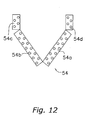
- the heat exchanger in which the lengths of the second heat exchange unit and the third heat exchange unit are the same will have a smaller maximum amount of error in the positions of the end portions of the heat exchanger due to error in the attachment angle than the heat exchanger in which the lengths of the second heat exchange unit and the third heat exchange unit are different.
- the lengths of the second heat exchange unit and the third heat exchange unit are different, one of the heat exchange units will be longer and the other will be shorter. In this situation, position error in the end portions of the heat exchanger due to the long heat exchange unit will increase.
- the lengths of the heat exchange units when the lengths of the second heat exchange unit and the third heat exchange unit are the same will be shorter than the length of the long heat exchange unit when the lengths are different.
- the heat exchanger disclosed in claim 2 is the heat exchanger disclosed in claim 1, in which the first heat exchange unit has an approximate inverted V shape in cross-section. Then, the second heat exchange unit and the third heat exchange unit respectively extend downward from the front and rear lower ends of the first heat exchange unit.
- the lengths of the second heat exchange unit and the third heat exchange unit are approximately the same, and thus the maximum amount of error in the positions of the lower ends of the heat exchanger due to error in the attachment angle will decrease.
- the error tolerance of the attachment angle of the second heat exchange unit and the third heat exchange unit can be relaxed.
- the heat exchanger disclosed in claim 3 is the heat exchanger disclosed in claim 1 or claim 2, in which the heat exchanger is symmetrical from front to rear, and the second heat exchange unit and the third heat exchange unit are symmetrical from front to rear.
- the lengths of the second heat exchange unit and the third heat exchange unit are approximately the same because the second heat exchange unit and the third heat exchange unit are symmetrical from front to rear.
- the error tolerance of the attachment angle of the second heat exchange unit and the third heat exchange unit can be relaxed.
- An indoor unit of an air conditioner disclosed in claim 4 includes the heat exchanger disclosed in any of claims 1 to 3, and a ventilation fan that is disposed so as to be covered by the heat exchanger.
- the ventilation fan is disposed so as to be covered by the heat exchanger.
- the precision of the distance between the heat exchanger and the ventilation fan is important.
- the shape of the heat exchanger preferably has a high degree of accuracy.
- the indoor unit of an air conditioner disclosed in claim 5 includes a ventilation fan, a heat exchanger, a first drain pan, a second drain pan, and a drain path.
- the heat exchanger is the heat exchanger disclosed in claim 1, covers the front, upper and rear portions of the ventilation fan, and is disposed so that the lower front end and the lower rear end of the heat exchanger are at the height of the apex of the ventilation fan or lower.
- the first drain pan is disposed below the lower front end of the heat exchanger.
- the second drain pan is disposed below the lower rear end of the heat exchanger. Drain water that is discharged from the first drain pan and the second drain pan passes through the drain path. Then, the first drain pan and the second drain pan are disposed at approximately the same height.
- the heat exchanger will function as a vaporizer during cooling and the like, and thus moisture in the air will condense on the surface of the heat exchanger and generate drain water.
- the indoor unit of an air conditioner will normally include a drain pan that receives drain water. This drain pan will normally be disposed below the heat exchanger in order to receive the drain water that drips down from the heat exchanger.
- drain pans will be respectively disposed below the lower front end and the lower rear end of the heat exchanger.
- the height at which the front drain pan and the rear drain pan are disposed is often different (see Japanese Unexamined Patent Publication No. 2000-74409).
- the front drain pan is disposed lower and the rear drain pan is disposed higher, or the front drain pan is disposed higher and the rear drain pan is disposed lower.
- the drain water that drips down into the drain pans is discharged to the exterior of the indoor unit from an outlet of the drain pans via a drain path.
- the heat exchanger is often brought close to the ventilation fan, and disposed so that the lower ends of the heat exchanger are lower than the apex of the ventilation fan.
- the positions of the lower ends of the heat exchanger are lowered, the positions of the drain pans will also be lowered. Because of this, the difference in height of the drain pans and the drain path will be smaller, and it will be difficult to discharge the drain water efficiently.
- the upward movement of the drain pans is limited because the drain pans are disposed below the heat exchanger.
- the position of one of the drain pans will be lower. Because of this, the difference in height of the positions of the drain path and the drain pans will be smaller.
- the first drain pan and the second drain pan that are disposed below the lower ends of the heat exchanger are disposed at approximately the same height.
- the lowering of one of the drain pans can be suppressed.
- the difference in height of the drain path that discharges drain water and the drain pans can be largely ensured.
- the indoor unit of an air conditioner disclosed in claim 6 is the indoor unit of an air conditioner disclosed in claim 5, in which the heat exchanger has an approximate inverted V shape in cross-section.
- the heat exchanger has an approximate inverted V shape in cross-section. Because of this, by disposing the ventilation fan in a space that is surrounded by the inverted V shaped heat exchanger, the front, upper and rear portions of the ventilation fan will be covered, and the lower ends of the heat exchanger can be easily disposed so as to be lower than the apex of the ventilation fan. Thus, the indoor unit of an air conditioner can be reduced in size in the height direction.
- the heat exchanger not only has a cross-sectional shape consisting only of the approximate inverted V shape portion, but may also have a cross-sectional shape that is formed by the approximate inverted V shaped portion and portions that extend downward from both lower ends thereof.
- the indoor unit for an air conditioner disclosed in claim 7 is the indoor unit of an air conditioner disclosed in claim 5 or claim 6, in which the lower front end and the lower rear end of the heat exchanger are positioned at approximately the same height.
- the lower front end and the lower rear end of the heat exchanger are positioned at approximately the same height. Then, the first drain pan and the second drain pan are respectively disposed below the lower front end and the lower rear end of the heat exchanger.
- the first drain pan and the second drain pan can be disposed at approximately the same height.
- the indoor unit of an air conditioner disclosed in claim 8 is the indoor unit of an air conditioner disclosed in any of claims 5 to 7, in which the heat exchanger has a shape that is symmetrical from front to rear.
- the heat exchanger has a shape that is symmetrical from front to rear.
- the heat exchanger is shaped so that the lower front end and the lower rear end thereof will be at the same height. Because of this, even if the first drain pan and the second drain pan are disposed in positions close to the heat exchanger, the first drain pan and the second drain pan can be disposed at approximately the same height.
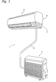
- FIG. 1 The exterior of an air conditioner in which an embodiment of the present invention has been adapted is shown in Fig 1.
- the air conditioner 1 includes an indoor unit 2 that is installed on an indoor wall surface or the like, and an outdoor unit 3 that is disposed outdoors.
- An indoor heat exchanger 50 is accommodated in the indoor unit 2
- an outdoor heat exchanger 30 is accommodated in the outdoor unit 3
- a refrigerant circuit is formed by connecting each heat exchanger 30, 50 by means of a refrigerant line 4.
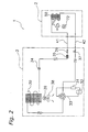
- the configuration of a refrigerant circuit of the air conditioner 1 is shown in Fig. 2.
- the refrigerant circuit is formed primarily of the indoor heat exchanger 50, an accumulator 31, a compressor 32, a four-way switching valve 33, an outdoor heat exchanger 30, and an electric expansion valve 34.
- the indoor heat exchanger 50 that is provided in the indoor unit 2 exchanges heat with the air that it comes into contact with.
- a cross flow fan 71 that serves to discharge air indoors after indoor air is taken in, passed through the indoor heat exchanger 50, and heat exchange has taken place, is provided in the indoor unit 2.
- This cross flow fan 71 is formed into a long, narrow cylindrical shape, and is disposed so that the central axis thereof is parallel in the horizontal direction.
- the cross flow fan 71 is rotatively driven by means of an indoor fan motor 72 that is provided inside the indoor unit 2. The detailed structure of the indoor unit 2 will be described below.
- a compressor 32, a four-way switching valve 33 that is connected to the discharge side of the compressor 32, an accumulator 31 that is connected to the intake side of the compressor 32, an outdoor heat exchanger 30 that is connected to the four-way switching valve 33, and an electric expansion valve 34 that is connected to the outdoor heat exchanger 30, are provided in the outdoor air conditioning unit 3.
- the electric expansion valve 34 is connected to a line 41 via a filter 35 and a liquid shut off valve 36, and is connected to one end of the indoor heat exchanger 50 via the line 41.
- the four way directional control valve 33 is connected to a line 42 via a gas shut off valve 37, and is connected to the other end of the indoor heat exchanger 50 via this line 42.
- a propeller fan 38 that serves to discharge air outside after heat exchange with the outdoor heat exchanger 30 is provided in the outdoor unit 3.
- the propeller fan 38 is rotatively driven by an outdoor fan motor 39.
- FIG. 3(a) A front view of the indoor unit is shown in Fig. 3(a), and a side view of the indoor unit 2 is shown in Fig. 3(b).
- the indoor unit 2 is rectangular in shape in the horizontal direction when viewed from the front, and has a vertical two tone color scheme when viewed from the front and from the sides.
- the indoor unit 2 is formed primarily by an upper casing 6, a lower unit 7, and an indoor heat exchanger unit 5 that is accommodated in the interior of the indoor unit 2.
- the upper casing 6 covers the upper portion of the indoor unit 2.
- the lower unit 7 forms the lower portion of the indoor unit 2.
- the upper casing 6 and the lower unit 7 are formed into separate members, and the border between the upper casing 6 and a portion of the lower unit 7 appears as a horizontal line on the exterior of the indoor unit 2.
- the upper casing 6 and a portion of the lower unit 7 are different colors, and the horizontal line that is the border between the upper casing 6 and the lower unit 7 forms the vertical two color scheme.
- the indoor heat exchange unit 5 is formed by the indoor heat exchanger 50, auxiliary lines 51, an auxiliary support member 52, and the like. Note that Fig. 4 is a right side view of the indoor unit 2 with the upper casing 6 removed.
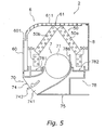
- Fig. 5 shows a cross-sectional side view of the indoor unit 2.
- the indoor heat exchanger 50 is installed so as to surround the front, upper, and rear portions of the cross flow fan 71, and air drawn in from intake ports 601, 611 by rotating the cross flow fan 71 passes through the indoor heat exchanger 50 to the cross flow fan 71, and heat exchange is performed with the refrigerant that passes through the interior of a heat transfer line.
- the indoor heat exchanger 50 is divided into four components: a first indoor heat exchanger 50a, a second indoor heat exchanger 50b, a third indoor heat exchanger 50c, and a fourth indoor heat exchanger 50d.
- the indoor heat exchanger 50 is formed so as to have an approximate inverted V-shape in cross-section whose both ends are bent downward when viewed from the sides.
- Each of the indoor heat exchangers 50a, 50b, 50c, and 50d have a long plate shape in the horizontal direction.
- Each of the indoor heat exchangers 50a, 50b, 50c, and 50d are formed from a heat transfer line that is folded back a plurality of times at both ends thereof, and a plurality of fins having short strip shapes in which the heat transfer line is inserted.
- the heat transfer line is folded back by means of U-shaped heat transfer lines at both side ends of each of the indoor heat exchangers 50a, 50b, 50c, and 50d.
- the upper end of the first indoor heat exchanger 50a is inclined toward the front of the indoor unit 2, and the first indoor heat exchanger 50a is disposed so as to cover the cross flow fan 71 from the upper central portion thereof to the upper rear side thereof.
- the upper end of the second indoor heat exchanger 50b is inclined toward the rear of the indoor unit 2, and the second indoor heat exchanger 50b is disposed forward of the first indoor heat exchanger 50a.
- the upper end of the second indoor heat exchanger 50b is connected to the upper end of the first indoor heat exchanger 50a, and the first indoor heat exchanger 50a and the second indoor heat exchanger 50b are combined so as to form an inverted V shape when viewed from the sides.
- the second indoor heat exchanger 50b is disposed so as to cover the cross flow fan 71 from the upper central portion to the upper front side.
- the third indoor heat exchanger 50c is disposed on the lower portion of the second indoor heat exchanger 50b so as to cover the front portion of the cross flow fan 71.
- the upper end of the third indoor heat exchanger 50c is connected at an angle to the lower end of the second indoor heat exchanger 50b, and an obtuse angle is formed by means of the third indoor heat exchanger 50c and the second indoor heat exchanger 50b.
- the third indoor heat exchanger 50c is parallel with the height direction, i.e., the perpendicular direction, and is perpendicular with respect to the lower unit 7 that covers the horizontal surface of the lower portion of the indoor heat exchanger 50.
- the lower end of the third indoor heat exchanger 50c is the lower end of the indoor heat exchanger 50, and the lower end of the third indoor heat exchanger 50c, i.e., the lower end of the front side of the indoor heat exchanger 50, is positioned at approximately the same height as the central axis of the cross flow fan 71.
- the fourth indoor heat exchanger 50d is disposed on the lower portion of the first indoor heat exchanger 50a so as to cover the rear portion of the cross flow fan 71.
- the upper end of the fourth indoor heat exchanger 50d is connected at an angle to the lower end of the first indoor heat exchanger 50a, and an obtuse angle is formed by means of the fourth indoor heat exchanger 50d and the first indoor heat exchanger 50a.
- the fourth indoor heat exchanger 50d is parallel with the height direction, and is perpendicular with respect to the lower unit 7 that covers the horizontal surface of the lower portion of the indoor heat exchanger 50.
- the lower end of the fourth indoor heat exchanger 50d is the lower end on the rear side of the indoor heat exchanger 50, and the lower end of the fourth indoor heat exchanger 50d, i.e., the lower end of the rear side of the indoor heat exchanger 50, is positioned at approximately the same height as the central axis of the cross flow fan 71.
- the third indoor heat exchanger 50c and the fourth indoor heat exchanger 50d have the same height in the height direction, and the upper and lower ends of the third indoor heat exchanger 50c and the fourth indoor heat exchanger 50d are positioned at the same height.
- the lower end of the front side and the lower end of the rear side of the indoor heat exchanger 50 have the same height, and are positioned at approximately the same height as the central axis of the cross flow fan 71.
- the lower ends on the front and rear sides of the indoor heat exchanger 50 extend from the lower ends on the front and rear of the inverted V shaped portion downward in the perpendicular direction to approximately the same height as the central axis of the cross flow fan 71.
- the first indoor heat exchanger 50a, the second indoor heat exchanger 50b, the third indoor heat exchanger 50c, and the fourth indoor heat exchanger 50d are unitarily connected to form the indoor heat exchanger 50 by mutually fixing attachment plates that are arranged on both side ends (the ends in the vertical direction when viewed from the front).
- the indoor heat exchanger 50 has a cross-sectional shape that is a combination of the inverted V shaped portion that is formed by the first indoor heat exchanger 50a and the second indoor heat exchanger 50b, and the straight portions that extend downward in the perpendicular direction from the respective lower ends of the first indoor heat exchanger 50a and the second indoor heat exchanger 50b.
- the indoor heat exchanger 50 has a linearly symmetrical cross-sectional shape from front to back with regard to a parallel line in the perpendicular direction that passes through the apex of the inverted V shape, and the first indoor heat exchanger 50a and the second indoor heat exchanger 50b, and the third indoor heat exchanger 50c and the fourth indoor heat exchanger 50d, are symmetrical from front to back.
- the indoor heat exchanger 50 is formed into a cross-sectional shape that includes a front to back symmetrical inverted V shape when viewed from the sides, as noted above, however, when viewed from the front, us rectangular in shape in the horizontal direction.
- the auxiliary lines 51 connect the indoor heat exchanger 50 with the refrigerant line 4 that are on the exterior of the indoor unit 2, and allows refrigerant to flow back and forth between the indoor heat exchanger 50 and the outdoor heat exchanger 30. As shown in Figs. 4 and 6, the auxiliary lines 51 are connected to the heat transfer line of the indoor heat exchanger 50. Note that Fig. 6 is a plan view of the right side portion of the indoor unit 2 with the upper casing 6 removed. The auxiliary lines 51 project out from the right side of the indoor heat exchanger 50, and pass through the space on the right side of the indoor heat exchanger 50.
- the auxiliary lines 51 curve toward the back surface of the indoor unit 2 after projecting out from the right side of the indoor heat exchanger 50, and the plurality of the auxiliary lines 51 are gathered together and covered by a protective tube 53.
- the gathered auxiliary lines 51 extend downward in the space on the right side of the indoor heat exchanger 50 along the back surface of the indoor unit 2, further curve toward the left side surface of the indoor unit 2 in the lower rear space of the indoor unit 2, and are connected to the refrigerant line 4.
- An auxiliary support member 52 is provided near both side surfaces of the indoor heat exchanger 50, and as shown in Fig. 4, supports the indoor heat exchanger 50 from the inner side thereof. Because the indoor heat exchange unit 5 has an inverted V shape and opens downward, the indoor heat exchange unit 5 is placed from above on the lower unit 7 on which the cross flow fan 71 and the indoor fan motor 72 have already been installed, and is supported by the lower unit 7 via the auxiliary support member 52.
- the upper casing 6 forms the upper portion of the indoor unit 2, and is formed by an upper front surface 60, a top surface 61, and upper side surfaces 62, 63.
- the upper front surface 60 covers the upper front side of the indoor unit 2, and covers the front of the indoor heat exchanger 50.
- the upper front surface 60 is formed to be substantially flat, and a stepped portion is provided on a portion thereof.
- a front surface intake port 601 composed of a long slit shaped opening in the longitudinal direction of the indoor unit 2 is provided in the upper surface of the stepped portion.
- the front surface intake port 601 is arranged toward the top of the indoor unit 2.
- the top surface 61 covers the top surface of the indoor unit 2, and covers the upper portion of the indoor heat exchanger 50.
- Top surface intake portions 611 composed of a plurality of slit shaped openings are provided in the top surface 61.
- the top surface intake ports 611 are arranged from the front side to the rear side of the top surface 61, and have a larger intake area than the front surface intake port 601. Because of this, sufficient air is also drawn in from the rear side of the top surface of the indoor unit 2.
- the upper side surfaces 62, 63 cover the upper portions of the side surfaces of the indoor unit 2, and cover the side portions of the indoor heat exchanger 50.
- the upper side surface 62, 63 is the upper right side surface 62 and the upper side surface 63 is the upper left side surface 63, and when viewed from the front, the upper right side surface 62 is disposed on the right side of the indoor heat exchanger 50 and the upper left side surface 63 is disposed on the left side of the indoor heat exchanger 50.
- the lower end of the upper casing 6 is formed horizontally, and by placing the upper casing 6 on the lower unit 7, the boundary between the upper casing 6 and the lower unit 7 will be a horizontal line, and will appear when viewed from the front and the sides of the indoor unit 2.
- the lower unit 7 forms the lower portion of the indoor unit 2, and as shown in Figs. 7 and 8, the lower casing 70, the cross flow fan 71, the indoor fan motor 72, the electric component box 73, and the like are in modulized form.
- the lower casing 70 is formed by a lower front surface 74, a bottom surface 75, lower side surfaces 76, 77, a support portion 78, and the like, and has a color that is different from that of the upper casing 6.
- the lower front surface 74 is a component that visually appears as the lower front surface of the indoor unit 2 when viewed from the front, and the upper end thereof is disposed so as to incline on the front of the indoor unit 2.
- the upper end of the lower front surface 74 is formed horizontally, and forms a horizontal border line together with the lower end of the upper casing 6.
- a discharge port 741 composed of an opening along the longitudinal direction of the indoor unit 2 is arranged in the lower front surface 74.
- the discharge port 741 communicates with a space in the interior of the support portion 78 in which the cross flow fan 71 is accommodated, and the air flow produced by the cross flow fan 71 is discharged indoors through the discharge port 741.
- a horizontal flap 742 that guides the air discharged indoors is arranged in the discharge port 741.
- the horizontal flap 742 is rotatively arranged in the center of a shaft that is parallel in the longitudinal direction of the indoor unit 2, and can open and close the discharge port 741 by being rotatively driven by a flap motor (not shown in the figures).
- the bottom surface 75 covers the bottom surface of the indoor unit 2, and is formed to be flat.
- the bottom surface 75 is disposed horizontally, and the support portion 78 is disposed on top thereof.
- the lower side surfaces 76, 77 are components that visually appear as lower side surfaces of the indoor unit 2 when viewed from the sides, and cover the lower side surfaces of the indoor unit 2.
- the lower side surface 76 is the lower right side surface 76 and the lower side surface 77 is the lower left side surface 77, and when viewed from the front, the lower right side surface 76 is disposed on the right side of the indoor unit 2 and the lower left side surface 77 is disposed on the left side of the indoor heat exchanger 50.
- the upper ends of the lower side surfaces 76, 77 are formed horizontally in the same way as the lower front surface 74. With the upper casing 6 placed on the lower unit 7, the lower end of the upper casing 6, and the upper ends of the lower front surface 74 and the lower side surfaces 76, 77 of the lower unit 7 meet to form a horizontal boundary line.
- the support portion 78 is surrounded by the lower side surface 74, the bottom surface 75, and the lower side surfaces 76, 77, and the upper surface of the support portion 78 is positioned above the upper ends of the lower front surface 74 and the lower side surfaces 76, 77.
- the cross flow fan 71, the indoor fan motor 72, the electric component box 73, the indoor heat exchange unit 5, and the like are installed from above on the support portion 78, and the cross flow fan 71, the indoor fan motor 72, the electric component box 73, the indoor heat exchange unit 5, and the like are supported from below.
- the support portion 78 supports the indoor heat exchanger 50 via the auxiliary support portion 52 of the indoor heat exchange unit 5.
- the upper surface of the support portion 78 is at approximately the same height as the central axis of the cross flow fan 71.
- drain pans 781, 782 and a fan accommodation portion 787 are provided on the upper surface of the support portion 78.
- the drain pans 781, 782 are components that receive water drops that are produced on the surface of the indoor heat exchanger 50 during heat exchange, and are formed from concave members that are sunken downward from the upper surface of the support portion 78.
- a front drain pan 781 and a rear drain pan 782 are the drain pans 781, 782, and as shown in Fig. 5, the front drain pan 781 is disposed below the third indoor heat exchanger 50c, i.e., below the front lower end of the indoor heat exchanger 50.
- the rear drain pan 782 is disposed below the fourth indoor heat exchanger 50d, i.e., below the rear lower end of the indoor heat exchanger 50.
- the front drain pan 781 and the rear drain pan 782 are disposed to interpose the cross flow fan 71 from front to rear.
- the front drain pan 781 and the rear drain pan 782 are positioned at approximately the same height, and the bottom surface of the front drain pan 781 and the rear drain pan 782 are positioned lower than the height of the central shaft of the cross flow fan 71, but are disposed near the lower ends of the indoor heat exchanger 50.
- the bottom surfaces of the front drain pan 781 and the rear drain pan 782 that receive the drain water are slightly inclined toward the right side of the indoor unit 2. Then, as shown in Fig.
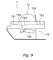
- a communicating portion 783 that connects the front drain pan 781 and the rear drain pan 782 is provided on the right side portion of the support portion 78, and a water removal hole 784 which penetrates the communication portion 783 downward is arranged.
- the water removal hole 784 communicates with the interior of a drain hose 785 that serves to discharge drain water from the drain pans 781, 782 to the exterior.
- the drain water that drains from the indoor heat exchanger 50 is received by the front drain pan 781 and the rear drain pan 782, is collected by the communicating portion 783, and is discharged from the water removal hole 784 to the exterior of the device via the drain hose 785.
- the fan accommodation portion 787 is a portion in which the cross flow fan 71 and the fan motor 72 are accommodated, and is arranged near the center of the upper surface of the support portion 78.
- the fan accommodation portion 787 is formed by means of a member that is sunk downward into a semi-circular shape from the upper surface of the support portion 78, and accommodates the lower half of the cross flow fan 71 and the indoor fan motor 72.
- an air path that communicates with the accommodated cross flow fan 71 and the discharge port 741 is arranged in the interior of the support portion 78.
- the support portion 78 includes a tongue portion 786 that projects upward from the upper surface of the support portion 78 between the rear drain pan 782 and the cross flow fan 71.
- the tongue portion 786 covers the rear portion of the cross flow fan 71, and the upper end of the tongue portion 786 is positioned at a somewhat lower height than the apex of the cross flow fan 71.
- front drain pan 781, the rear drain pan 782, and the fan accommodation portion 787 are arranged on the upper surface of the support portion 78, and the tongue portion 786 projects upward, other portions on the upper surface of the support portion 78 are formed to be flat and horizontal, and are positioned at approximately the same height as the central axis of the cross flow fan 71.
- the portion that is positioned at the highest position on the support portion 78 is the tongue portion 786, but the tongue portion 786 is positioned at the height of the apex of the cross flow fan 71 or lower.
- the upper surface of the support portion 78 is positioned above the upper surfaces of the lower front surface 74 and the lower side surfaces 76, 77. Because of this, each portion of the lower casing 70, including the support portion 78, is at the height of the apex of the cross flow fan 71 or lower.
- the back surface side of the upper surface of the support portion 78 is also at the height of the cross flow fan 71 or lower, but the portion between the top surface 61 of the upper casing 6 and the back surface side of the upper surface of the support portion 78 is closed by means of an installation plate that is installed on an indoor wall surface (refer to Fig. 5).
- the installation plate 8 has a length that is approximately the same as the indoor heat exchanger 50 in the longitudinal direction of the indoor unit 2, and covers the back surface side of the indoor heat exchanger 50.
- the installation plate 8 forms, by covering the back surface side of the indoor unit 2, together with the upper casing 6, an air path through which air that exchanges heat with the indoor heat exchanger 50 passes, especially an air path of the back surface side.
- the cross flow fan 71 is formed into a long, narrow cylindrical shape, and is disposed so that the central axis thereof is parallel with the horizontal direction. Blades are arranged on the circumferential surface of the cross flow fan 71, and the cross flow fan 71 will produce an air flow by rotating around the central axis. This air flow is taken in from the front surface intake port 601 and the top surface intake ports 611, and is an air flow that passes through the indoor heat exchanger 50 and is discharged indoor from the discharge port 741.
- the cross flow fan 71 is positioned in the approximate center of the indoor unit 2 when viewed from the sides.
- the cross flow fan 71 is supported by the support portion 78, and when supported, the upper half of the cross flow fan projects upward from the upper surface of the support portion 78.
- the indoor fan motor 72 rotatively drives the cross flow fan 71 around the central axis.
- the indoor fan motor 72 has a thin cylindrical shape having approximately the same diameter as the cross flow fan 71. As shown in Fig. 8, the indoor fan motor 72 is disposed in approximately the same axis as the cross flow fan 71 on the right side of the cross flow fan 71, and the indoor fan motor 72 has approximately the same height as the apex of the cross flow fan 71 when the indoor fan motor 72 installed on the support portion 78 (refer to Fig. 7).
- the electric component box 73 accommodates a control board 731 that serves to control the operation of the indoor unit 2.
- the electric component box 73 has a rectangular box shape, is disposed between the right lower surface 76 of the lower casing 70 and the support portion 78, and is positioned on the right side of the indoor heat exchanger unit 5.
- the electric component box 73 is installed and supported on the right side surface of the support portion 78 to the right of the indoor fan motor 72, and can be installed on the support portion 78 before the indoor heat exchange unit 5 is installed on the lower unit 7.
- the electric component box 73 is disposed toward the front side, and the space to the rear of the electric component box 73 is the space noted above through which the auxiliary lines 51 of the indoor heat exchange unit 5 pass.
- the electric component box 73 is disposed such that the strong electric components 732, such as the condenser, the power transistor, and the like which take up a large amount of space amongst the control components installed on the control board 731, are lined up in the axial direction with the indoor fan motor 72, and is disposed such that the indoor fan motor 72 and the electric component box 73 are behind one another when viewed from the sides.
- the upper surface of the electric component box 73 is positioned at approximately the same height as the apex of the indoor fan motor 72, i.e., the apex of the cross flow fan 71, when the electric component box 73 is supported on the lower casing 70.
- the indoor fan motor 72, the electric component box 73, and all of the components of the lower casing 70 are positioned at the height of the apex of the cross flow fan 71 or lower when supported on the lower casing 70, and the lower unit 7 has an overall comparatively small dimensional shape in the height direction.
- the heat exchanger and the indoor unit of the air conditioner of the present invention are used, a reduction in heat exchangeability can be suppressed, and the error tolerance of the attachment angle of the heat exchanging units can be relaxed.
Landscapes
- Engineering & Computer Science (AREA)
- Chemical & Material Sciences (AREA)
- Combustion & Propulsion (AREA)
- Mechanical Engineering (AREA)
- General Engineering & Computer Science (AREA)
- Physics & Mathematics (AREA)
- Thermal Sciences (AREA)
- Air Filters, Heat-Exchange Apparatuses, And Housings Of Air-Conditioning Units (AREA)
- Air-Conditioning Room Units, And Self-Contained Units In General (AREA)
Abstract
The present invention provides a heat exchanger and an indoor unit of an air
conditioner that can both suppress a reduction in heat exchangeability and relax
the error tolerance of the attachment angle of the heat exchange units. The
indoor heat exchanger (50) is a heat exchanger (50) that is formed by connecting
a plurality of heat exchangers (50a, 50b, 50c, 50d), disposed in the indoor unit
(2) of an air conditioner, and includes a first indoor heat exchanger (50a), a
second indoor heat exchanger (50b), a third indoor heat exchanger (50c), and a
fourth indoor heat exchanger (50d). The third indoor heat exchanger (50c) is
connected at an angle to one end of the first indoor heat exchanger (50a) and
the second indoor heat exchanger (50b). The fourth indoor heat exchanger (50d)
is connected at an angle to another end of the first indoor heat exchanger (50a)
and the second indoor heat exchanger (50b). Then, the third indoor heat
exchanger (50c) and the fourth indoor heat exchanger (50d) will have the same
approximate height.
Description
The present invention relates to a heat exchanger, and more particularly to a
heat exchanger that is disposed in an indoor unit of an air conditioner, and an
indoor unit of an air conditioner.
Heat exchangers that are formed by combining a plurality of heat exchange
units at an angle are conventionally used. This type of heat exchanger can be
formed into a variety of shapes that meet design needs and the like by combining
heat exchange units. Many of the plurality of heat exchange units that form the
heat exchanger have various lengths (see Japanese Unexamined Patent
Publication No. 2001-4162). For example, there is a heat exchanger that makes
up a portion of an indoor unit of an air conditioner that is formed into an inverted
V shape so as to surround a ventilation fan. This heat exchanger is a
combination of heat exchange units of various lengths which are formed into an
inverted V shape, and the heat exchange units that cover the front of the
ventilation fan and heat exchange units that cover the rear of the ventilation fan
have different lengths.
When a heat exchanger formed by means of a plurality of heat exchange units
that are angled and combined together is assembled, errors in the attachment
angle of the heat exchange units will create problems. In other words, when
there are errors in the attachment angle of the heat exchange units, errors will be
produced in the positions of the end portions of the heat exchanger, and thus
problems may be produced in the positioning and the like of the heat exchanger.
Thus, errors in the attachment angle of the heat exchange units are preferably as
small as possible, but if a very severe error tolerance is required, the ability to
assemble the heat exchanger will be reduced.
On the other hand, errors in the position of the end portions of the heat
exchanger will become larger as the length of the heat exchange units become
longer, even if the errors in the attachment angle of the heat exchange units are
the same. Because of this, it is thought that the error tolerance of the attachment
angle can be relaxed by shortening the lengths of the heat exchange units.
However, if the lengths of the heat exchange units are shortened, there will be
an impact on the heat exchangeability of the heat exchanger. In other words, if
the lengths of the heat exchange units are shortened, the overall surface area of
the heat exchanger (the sum of the surface area of each heat exchange unit) will
decrease, and the heat exchangeability of the heat exchanger will be reduced.
Thus, simply shortening the lengths of the heat exchange units in order to relax
the error tolerance of the attachment angle of the heat exchange units will give
rise to a reduction in heat exchangeability.
An object of the present invention is to provide a heat exchanger and an indoor
unit of an air conditioner that can both suppress a reduction in heat
exchangeability and relax the error tolerance of the attachment angle of the heat
exchange units.
The heat exchanger disclosed in claim 1 is a heat exchanger that is formed by
connecting a plurality of heat exchange units, is disposed in an indoor unit of an
air conditioner, and includes a first heat exchange unit, a second heat exchange
unit, and a third heat exchange unit. The second heat exchange unit is
connected at an angle with one end of the first heat exchange unit. The third heat
exchange unit is connected at an angle with the other end of the first heat
exchange unit. Then, the second heat exchange unit and the third heat exchange
unit will have approximately the same length.
With this heat exchanger, the second heat exchange unit and the third heat
exchange unit have approximately the same length. When the total length of heat
exchangers are the same, the heat exchanger in which the lengths of the second
heat exchange unit and the third heat exchange unit are the same will have a
smaller maximum amount of error in the positions of the end portions of the heat
exchanger due to error in the attachment angle than the heat exchanger in which
the lengths of the second heat exchange unit and the third heat exchange unit
are different. In other words, when the lengths of the second heat exchange unit
and the third heat exchange unit are different, one of the heat exchange units will
be longer and the other will be shorter. In this situation, position error in the end
portions of the heat exchanger due to the long heat exchange unit will increase.
On the other hand, if the total length of the heat exchanger is the same, the
lengths of the heat exchange units when the lengths of the second heat
exchange unit and the third heat exchange unit are the same will be shorter than
the length of the long heat exchange unit when the lengths are different. Thus,
with this heat exchanger, a reduction in heat exchangeability can be suppressed
and the error tolerance of the attachment angle of the heat exchange units can
be relaxed.
The heat exchanger disclosed in claim 2 is the heat exchanger disclosed in
claim 1, in which the first heat exchange unit has an approximate inverted V
shape in cross-section. Then, the second heat exchange unit and the third heat
exchange unit respectively extend downward from the front and rear lower ends
of the first heat exchange unit.
When the lower ends of the second heat exchange unit and the third heat
exchange unit are the respective lower ends of the heat exchanger, errors in the
attachment angle of the second heat exchange unit and the third heat exchange
unit will have an impact on the position error of the lower ends of the heat
exchanger.
However, with this heat exchanger, the lengths of the second heat exchange
unit and the third heat exchange unit are approximately the same, and thus the
maximum amount of error in the positions of the lower ends of the heat
exchanger due to error in the attachment angle will decrease. Thus, with this
heat exchanger, the error tolerance of the attachment angle of the second heat
exchange unit and the third heat exchange unit can be relaxed.
The heat exchanger disclosed in claim 3 is the heat exchanger disclosed in
claim 1 or claim 2, in which the heat exchanger is symmetrical from front to rear,
and the second heat exchange unit and the third heat exchange unit are
symmetrical from front to rear.
With this heat exchanger, the lengths of the second heat exchange unit and
the third heat exchange unit are approximately the same because the second
heat exchange unit and the third heat exchange unit are symmetrical from front
to rear. Thus, the error tolerance of the attachment angle of the second heat
exchange unit and the third heat exchange unit can be relaxed.
An indoor unit of an air conditioner disclosed in claim 4 includes the heat
exchanger disclosed in any of claims 1 to 3, and a ventilation fan that is disposed
so as to be covered by the heat exchanger.
With this indoor unit of an air conditioner, the ventilation fan is disposed so as
to be covered by the heat exchanger. Thus, in order to maintain the distance
between the heat exchanger and the ventilation fan at a predetermined value,
the precision of the distance between the heat exchanger and the ventilation fan
is important. Because of this, the shape of the heat exchanger preferably has a
high degree of accuracy. Thus, the present invention, which can relax the error
tolerance of the attachment angle between the second heat exchange unit and
the third heat exchanger unit, is very useful.
The indoor unit of an air conditioner disclosed in claim 5 includes a ventilation
fan, a heat exchanger, a first drain pan, a second drain pan, and a drain path.
The heat exchanger is the heat exchanger disclosed in claim 1, covers the front,
upper and rear portions of the ventilation fan, and is disposed so that the lower
front end and the lower rear end of the heat exchanger are at the height of the
apex of the ventilation fan or lower. The first drain pan is disposed below the
lower front end of the heat exchanger. The second drain pan is disposed below
the lower rear end of the heat exchanger. Drain water that is discharged from the
first drain pan and the second drain pan passes through the drain path. Then,
the first drain pan and the second drain pan are disposed at approximately the
same height.
Generally, in an indoor unit of an air conditioner that includes a heat exchanger,
the heat exchanger will function as a vaporizer during cooling and the like, and
thus moisture in the air will condense on the surface of the heat exchanger and
generate drain water. Because of this, the indoor unit of an air conditioner will
normally include a drain pan that receives drain water. This drain pan will
normally be disposed below the heat exchanger in order to receive the drain
water that drips down from the heat exchanger. Thus, when the heat exchanger
is disposed so as to cover the front and rear portions of the ventilation fan, drain
pans will be respectively disposed below the lower front end and the lower rear
end of the heat exchanger. In this configuration, the height at which the front
drain pan and the rear drain pan are disposed is often different (see Japanese
Unexamined Patent Publication No. 2000-74409). For example, the front drain
pan is disposed lower and the rear drain pan is disposed higher, or the front drain
pan is disposed higher and the rear drain pan is disposed lower.
The drain water that drips down into the drain pans is discharged to the
exterior of the indoor unit from an outlet of the drain pans via a drain path. In
this configuration, the bigger the difference in height between the position of the
drain pans and the position of the drain path, the more efficient the discharge of
the drain water will be.
On the other hand, from the point of view of reducing the height of the indoor
unit, the heat exchanger is often brought close to the ventilation fan, and
disposed so that the lower ends of the heat exchanger are lower than the apex of
the ventilation fan. Thus, if the positions of the lower ends of the heat exchanger
are lowered, the positions of the drain pans will also be lowered. Because of this,
the difference in height of the drain pans and the drain path will be smaller, and it
will be difficult to discharge the drain water efficiently.
In addition, the upward movement of the drain pans is limited because the
drain pans are disposed below the heat exchanger. Thus, if there is a difference
in height between the first drain pan and the second drain pan, the position of
one of the drain pans will be lower. Because of this, the difference in height of the
positions of the drain path and the drain pans will be smaller.
However, with this indoor unit of an air conditioner, the first drain pan and the
second drain pan that are disposed below the lower ends of the heat exchanger
are disposed at approximately the same height. Thus, the lowering of one of the
drain pans can be suppressed. Thus, with this indoor unit of an air conditioner,
the difference in height of the drain path that discharges drain water and the
drain pans can be largely ensured.
The indoor unit of an air conditioner disclosed in claim 6 is the indoor unit of
an air conditioner disclosed in claim 5, in which the heat exchanger has an
approximate inverted V shape in cross-section.
With this indoor unit of an air conditioner, the heat exchanger has an
approximate inverted V shape in cross-section. Because of this, by disposing the
ventilation fan in a space that is surrounded by the inverted V shaped heat
exchanger, the front, upper and rear portions of the ventilation fan will be
covered, and the lower ends of the heat exchanger can be easily disposed so as
to be lower than the apex of the ventilation fan. Thus, the indoor unit of an air
conditioner can be reduced in size in the height direction.
Note that the heat exchanger not only has a cross-sectional shape consisting
only of the approximate inverted V shape portion, but may also have a cross-sectional
shape that is formed by the approximate inverted V shaped portion and
portions that extend downward from both lower ends thereof.
The indoor unit for an air conditioner disclosed in claim 7 is the indoor unit of
an air conditioner disclosed in claim 5 or claim 6, in which the lower front end
and the lower rear end of the heat exchanger are positioned at approximately the
same height.
With this indoor unit of an air conditioner, the lower front end and the lower
rear end of the heat exchanger are positioned at approximately the same height.
Then, the first drain pan and the second drain pan are respectively disposed
below the lower front end and the lower rear end of the heat exchanger. Thus,
with this indoor unit of an air conditioner, even if the first drain pan and the
second drain pan are disposed in positions close to the lower ends of the heat
exchanger, the first drain pan and the second drain pan can be disposed at
approximately the same height.
The indoor unit of an air conditioner disclosed in claim 8 is the indoor unit of an
air conditioner disclosed in any of claims 5 to 7, in which the heat exchanger has
a shape that is symmetrical from front to rear.
With this indoor unit of an air conditioner, the heat exchanger has a shape that
is symmetrical from front to rear. Thus, the heat exchanger is shaped so that the
lower front end and the lower rear end thereof will be at the same height.
Because of this, even if the first drain pan and the second drain pan are disposed
in positions close to the heat exchanger, the first drain pan and the second drain
pan can be disposed at approximately the same height.
The exterior of an air conditioner in which an embodiment of the present
invention has been adapted is shown in Fig 1.
The air conditioner 1 includes an indoor unit 2 that is installed on an indoor
wall surface or the like, and an outdoor unit 3 that is disposed outdoors.
An indoor heat exchanger 50 is accommodated in the indoor unit 2, an
outdoor heat exchanger 30 is accommodated in the outdoor unit 3, and a
refrigerant circuit is formed by connecting each heat exchanger 30, 50 by means
of a refrigerant line 4.
The configuration of a refrigerant circuit of the air conditioner 1 is shown in
Fig. 2. The refrigerant circuit is formed primarily of the indoor heat exchanger
50, an accumulator 31, a compressor 32, a four-way switching valve 33, an
outdoor heat exchanger 30, and an electric expansion valve 34.
The indoor heat exchanger 50 that is provided in the indoor unit 2 exchanges
heat with the air that it comes into contact with. In addition, a cross flow fan 71
that serves to discharge air indoors after indoor air is taken in, passed through
the indoor heat exchanger 50, and heat exchange has taken place, is provided in
the indoor unit 2. This cross flow fan 71 is formed into a long, narrow cylindrical
shape, and is disposed so that the central axis thereof is parallel in the horizontal
direction. The cross flow fan 71 is rotatively driven by means of an indoor fan
motor 72 that is provided inside the indoor unit 2. The detailed structure of the
indoor unit 2 will be described below.
A compressor 32, a four-way switching valve 33 that is connected to the
discharge side of the compressor 32, an accumulator 31 that is connected to the
intake side of the compressor 32, an outdoor heat exchanger 30 that is
connected to the four-way switching valve 33, and an electric expansion valve 34
that is connected to the outdoor heat exchanger 30, are provided in the outdoor
air conditioning unit 3. The electric expansion valve 34 is connected to a line 41
via a filter 35 and a liquid shut off valve 36, and is connected to one end of the
indoor heat exchanger 50 via the line 41. In addition, the four way directional
control valve 33 is connected to a line 42 via a gas shut off valve 37, and is
connected to the other end of the indoor heat exchanger 50 via this line 42.
These lines 41, 42 correspond to the refrigerant line 4 shown in Fig. 1. In
addition, a propeller fan 38 that serves to discharge air outside after heat
exchange with the outdoor heat exchanger 30 is provided in the outdoor unit 3.
The propeller fan 38 is rotatively driven by an outdoor fan motor 39.
A front view of the indoor unit is shown in Fig. 3(a), and a side view of the
indoor unit 2 is shown in Fig. 3(b). The indoor unit 2 is rectangular in shape in
the horizontal direction when viewed from the front, and has a vertical two tone
color scheme when viewed from the front and from the sides.
The indoor unit 2 is formed primarily by an upper casing 6, a lower unit 7, and
an indoor heat exchanger unit 5 that is accommodated in the interior of the
indoor unit 2. The upper casing 6 covers the upper portion of the indoor unit 2.
The lower unit 7 forms the lower portion of the indoor unit 2. The upper casing
6 and the lower unit 7 are formed into separate members, and the border
between the upper casing 6 and a portion of the lower unit 7 appears as a
horizontal line on the exterior of the indoor unit 2. In addition, the upper casing
6 and a portion of the lower unit 7 are different colors, and the horizontal line that
is the border between the upper casing 6 and the lower unit 7 forms the vertical
two color scheme.
Each structure of the indoor unit 2 will be described below.
As shown in Fig. 4, the indoor heat exchange unit 5 is formed by the indoor
heat exchanger 50, auxiliary lines 51, an auxiliary support member 52, and the
like. Note that Fig. 4 is a right side view of the indoor unit 2 with the upper
casing 6 removed.
Fig. 5 shows a cross-sectional side view of the indoor unit 2.
The indoor heat exchanger 50 is installed so as to surround the front, upper,
and rear portions of the cross flow fan 71, and air drawn in from intake ports 601,
611 by rotating the cross flow fan 71 passes through the indoor heat exchanger
50 to the cross flow fan 71, and heat exchange is performed with the refrigerant
that passes through the interior of a heat transfer line. The indoor heat
exchanger 50 is divided into four components: a first indoor heat exchanger 50a,
a second indoor heat exchanger 50b, a third indoor heat exchanger 50c, and a
fourth indoor heat exchanger 50d. By connecting each of the indoor heat
exchangers 50a, 50b, 50c, and 50d, the indoor heat exchanger 50 is formed so
as to have an approximate inverted V-shape in cross-section whose both ends
are bent downward when viewed from the sides.
Each of the indoor heat exchangers 50a, 50b, 50c, and 50d have a long plate
shape in the horizontal direction. Each of the indoor heat exchangers 50a, 50b,
50c, and 50d are formed from a heat transfer line that is folded back a plurality of
times at both ends thereof, and a plurality of fins having short strip shapes in
which the heat transfer line is inserted. The heat transfer line is folded back by
means of U-shaped heat transfer lines at both side ends of each of the indoor
heat exchangers 50a, 50b, 50c, and 50d.
The upper end of the first indoor heat exchanger 50a is inclined toward the
front of the indoor unit 2, and the first indoor heat exchanger 50a is disposed so
as to cover the cross flow fan 71 from the upper central portion thereof to the
upper rear side thereof.
The upper end of the second indoor heat exchanger 50b is inclined toward
the rear of the indoor unit 2, and the second indoor heat exchanger 50b is
disposed forward of the first indoor heat exchanger 50a. The upper end of the
second indoor heat exchanger 50b is connected to the upper end of the first
indoor heat exchanger 50a, and the first indoor heat exchanger 50a and the
second indoor heat exchanger 50b are combined so as to form an inverted V
shape when viewed from the sides. The second indoor heat exchanger 50b is
disposed so as to cover the cross flow fan 71 from the upper central portion to
the upper front side.
The third indoor heat exchanger 50c is disposed on the lower portion of the
second indoor heat exchanger 50b so as to cover the front portion of the cross
flow fan 71. The upper end of the third indoor heat exchanger 50c is connected
at an angle to the lower end of the second indoor heat exchanger 50b, and an
obtuse angle is formed by means of the third indoor heat exchanger 50c and the
second indoor heat exchanger 50b. The third indoor heat exchanger 50c is
parallel with the height direction, i.e., the perpendicular direction, and is
perpendicular with respect to the lower unit 7 that covers the horizontal surface
of the lower portion of the indoor heat exchanger 50. In addition, the lower end
of the third indoor heat exchanger 50c is the lower end of the indoor heat
exchanger 50, and the lower end of the third indoor heat exchanger 50c, i.e., the
lower end of the front side of the indoor heat exchanger 50, is positioned at
approximately the same height as the central axis of the cross flow fan 71.
The fourth indoor heat exchanger 50d is disposed on the lower portion of the
first indoor heat exchanger 50a so as to cover the rear portion of the cross flow
fan 71. The upper end of the fourth indoor heat exchanger 50d is connected at
an angle to the lower end of the first indoor heat exchanger 50a, and an obtuse
angle is formed by means of the fourth indoor heat exchanger 50d and the first
indoor heat exchanger 50a. The fourth indoor heat exchanger 50d is parallel
with the height direction, and is perpendicular with respect to the lower unit 7 that
covers the horizontal surface of the lower portion of the indoor heat exchanger
50. In addition, the lower end of the fourth indoor heat exchanger 50d is the
lower end on the rear side of the indoor heat exchanger 50, and the lower end of
the fourth indoor heat exchanger 50d, i.e., the lower end of the rear side of the
indoor heat exchanger 50, is positioned at approximately the same height as the
central axis of the cross flow fan 71.
The third indoor heat exchanger 50c and the fourth indoor heat exchanger
50d have the same height in the height direction, and the upper and lower ends
of the third indoor heat exchanger 50c and the fourth indoor heat exchanger 50d
are positioned at the same height. Thus, the lower end of the front side and the
lower end of the rear side of the indoor heat exchanger 50 have the same height,
and are positioned at approximately the same height as the central axis of the
cross flow fan 71. In addition, the lower ends on the front and rear sides of the
indoor heat exchanger 50 extend from the lower ends on the front and rear of the
inverted V shaped portion downward in the perpendicular direction to
approximately the same height as the central axis of the cross flow fan 71.
The first indoor heat exchanger 50a, the second indoor heat exchanger 50b,
the third indoor heat exchanger 50c, and the fourth indoor heat exchanger 50d
are unitarily connected to form the indoor heat exchanger 50 by mutually fixing
attachment plates that are arranged on both side ends (the ends in the vertical
direction when viewed from the front). The indoor heat exchanger 50 has a
cross-sectional shape that is a combination of the inverted V shaped portion that
is formed by the first indoor heat exchanger 50a and the second indoor heat
exchanger 50b, and the straight portions that extend downward in the
perpendicular direction from the respective lower ends of the first indoor heat
exchanger 50a and the second indoor heat exchanger 50b. The indoor heat
exchanger 50 has a linearly symmetrical cross-sectional shape from front to back
with regard to a parallel line in the perpendicular direction that passes through
the apex of the inverted V shape, and the first indoor heat exchanger 50a and
the second indoor heat exchanger 50b, and the third indoor heat exchanger 50c
and the fourth indoor heat exchanger 50d, are symmetrical from front to back.
The indoor heat exchanger 50 is formed into a cross-sectional shape that
includes a front to back symmetrical inverted V shape when viewed from the
sides, as noted above, however, when viewed from the front, us rectangular in
shape in the horizontal direction.
The auxiliary lines 51 connect the indoor heat exchanger 50 with the
refrigerant line 4 that are on the exterior of the indoor unit 2, and allows
refrigerant to flow back and forth between the indoor heat exchanger 50 and the
outdoor heat exchanger 30. As shown in Figs. 4 and 6, the auxiliary lines 51
are connected to the heat transfer line of the indoor heat exchanger 50. Note
that Fig. 6 is a plan view of the right side portion of the indoor unit 2 with the
upper casing 6 removed. The auxiliary lines 51 project out from the right side of
the indoor heat exchanger 50, and pass through the space on the right side of
the indoor heat exchanger 50. The auxiliary lines 51 curve toward the back
surface of the indoor unit 2 after projecting out from the right side of the indoor
heat exchanger 50, and the plurality of the auxiliary lines 51 are gathered
together and covered by a protective tube 53. The gathered auxiliary lines 51
extend downward in the space on the right side of the indoor heat exchanger 50
along the back surface of the indoor unit 2, further curve toward the left side
surface of the indoor unit 2 in the lower rear space of the indoor unit 2, and are
connected to the refrigerant line 4.
An auxiliary support member 52 is provided near both side surfaces of the
indoor heat exchanger 50, and as shown in Fig. 4, supports the indoor heat
exchanger 50 from the inner side thereof. Because the indoor heat exchange
unit 5 has an inverted V shape and opens downward, the indoor heat exchange
unit 5 is placed from above on the lower unit 7 on which the cross flow fan 71
and the indoor fan motor 72 have already been installed, and is supported by the
lower unit 7 via the auxiliary support member 52.
As shown in Figs. 3 and 5, the upper casing 6 forms the upper portion of the
indoor unit 2, and is formed by an upper front surface 60, a top surface 61, and
upper side surfaces 62, 63.
The upper front surface 60 covers the upper front side of the indoor unit 2,
and covers the front of the indoor heat exchanger 50. The upper front surface
60 is formed to be substantially flat, and a stepped portion is provided on a
portion thereof. A front surface intake port 601 composed of a long slit shaped
opening in the longitudinal direction of the indoor unit 2 is provided in the upper
surface of the stepped portion. The front surface intake port 601 is arranged
toward the top of the indoor unit 2.
The top surface 61 covers the top surface of the indoor unit 2, and covers the
upper portion of the indoor heat exchanger 50. Top surface intake portions 611
composed of a plurality of slit shaped openings are provided in the top surface
61. The top surface intake ports 611 are arranged from the front side to the rear
side of the top surface 61, and have a larger intake area than the front surface
intake port 601. Because of this, sufficient air is also drawn in from the rear
side of the top surface of the indoor unit 2.
The upper side surfaces 62, 63 cover the upper portions of the side surfaces
of the indoor unit 2, and cover the side portions of the indoor heat exchanger 50.
The upper side surface 62, 63 is the upper right side surface 62 and the upper
side surface 63 is the upper left side surface 63, and when viewed from the front,
the upper right side surface 62 is disposed on the right side of the indoor heat
exchanger 50 and the upper left side surface 63 is disposed on the left side of
the indoor heat exchanger 50.
In addition, the lower end of the upper casing 6 is formed horizontally, and by
placing the upper casing 6 on the lower unit 7, the boundary between the upper
casing 6 and the lower unit 7 will be a horizontal line, and will appear when
viewed from the front and the sides of the indoor unit 2.
The lower unit 7 forms the lower portion of the indoor unit 2, and as shown in
Figs. 7 and 8, the lower casing 70, the cross flow fan 71, the indoor fan motor 72,
the electric component box 73, and the like are in modulized form.
The lower casing 70 is formed by a lower front surface 74, a bottom surface
75, lower side surfaces 76, 77, a support portion 78, and the like, and has a color
that is different from that of the upper casing 6.
The lower front surface 74 is a component that visually appears as the lower
front surface of the indoor unit 2 when viewed from the front, and the upper end
thereof is disposed so as to incline on the front of the indoor unit 2. As shown in
Fig. 3(a), the upper end of the lower front surface 74 is formed horizontally, and
forms a horizontal border line together with the lower end of the upper casing 6.
In addition, a discharge port 741 composed of an opening along the longitudinal
direction of the indoor unit 2 is arranged in the lower front surface 74. As shown
in Fig. 5, the discharge port 741 communicates with a space in the interior of the
support portion 78 in which the cross flow fan 71 is accommodated, and the air
flow produced by the cross flow fan 71 is discharged indoors through the
discharge port 741. In addition, a horizontal flap 742 that guides the air
discharged indoors is arranged in the discharge port 741. The horizontal flap
742 is rotatively arranged in the center of a shaft that is parallel in the
longitudinal direction of the indoor unit 2, and can open and close the discharge
port 741 by being rotatively driven by a flap motor (not shown in the figures).
The bottom surface 75 covers the bottom surface of the indoor unit 2, and is
formed to be flat. The bottom surface 75 is disposed horizontally, and the
support portion 78 is disposed on top thereof.
The lower side surfaces 76, 77 are components that visually appear as lower
side surfaces of the indoor unit 2 when viewed from the sides, and cover the
lower side surfaces of the indoor unit 2. The lower side surface 76 is the lower
right side surface 76 and the lower side surface 77 is the lower left side surface
77, and when viewed from the front, the lower right side surface 76 is disposed
on the right side of the indoor unit 2 and the lower left side surface 77 is
disposed on the left side of the indoor heat exchanger 50. In addition, the upper
ends of the lower side surfaces 76, 77 are formed horizontally in the same way
as the lower front surface 74. With the upper casing 6 placed on the lower unit
7, the lower end of the upper casing 6, and the upper ends of the lower front
surface 74 and the lower side surfaces 76, 77 of the lower unit 7 meet to form a
horizontal boundary line.
The support portion 78 is surrounded by the lower side surface 74, the bottom
surface 75, and the lower side surfaces 76, 77, and the upper surface of the
support portion 78 is positioned above the upper ends of the lower front surface
74 and the lower side surfaces 76, 77. The cross flow fan 71, the indoor fan
motor 72, the electric component box 73, the indoor heat exchange unit 5, and
the like are installed from above on the support portion 78, and the cross flow fan
71, the indoor fan motor 72, the electric component box 73, the indoor heat
exchange unit 5, and the like are supported from below.
The support portion 78 supports the indoor heat exchanger 50 via the
auxiliary support portion 52 of the indoor heat exchange unit 5. The upper
surface of the support portion 78 is at approximately the same height as the
central axis of the cross flow fan 71. As shown in Fig. 7, drain pans 781, 782
and a fan accommodation portion 787 are provided on the upper surface of the
support portion 78.
The drain pans 781, 782 are components that receive water drops that are
produced on the surface of the indoor heat exchanger 50 during heat exchange,
and are formed from concave members that are sunken downward from the
upper surface of the support portion 78. A front drain pan 781 and a rear drain
pan 782 are the drain pans 781, 782, and as shown in Fig. 5, the front drain pan
781 is disposed below the third indoor heat exchanger 50c, i.e., below the front
lower end of the indoor heat exchanger 50. The rear drain pan 782 is disposed
below the fourth indoor heat exchanger 50d, i.e., below the rear lower end of the
indoor heat exchanger 50. The front drain pan 781 and the rear drain pan 782
are disposed to interpose the cross flow fan 71 from front to rear. The front
drain pan 781 and the rear drain pan 782 are positioned at approximately the
same height, and the bottom surface of the front drain pan 781 and the rear drain
pan 782 are positioned lower than the height of the central shaft of the cross flow
fan 71, but are disposed near the lower ends of the indoor heat exchanger 50.
Note that the bottom surfaces of the front drain pan 781 and the rear drain pan
782 that receive the drain water are slightly inclined toward the right side of the
indoor unit 2. Then, as shown in Fig. 8, a communicating portion 783 that
connects the front drain pan 781 and the rear drain pan 782 is provided on the
right side portion of the support portion 78, and a water removal hole 784 which
penetrates the communication portion 783 downward is arranged. As shown in
Fig. 9, the water removal hole 784 communicates with the interior of a drain hose
785 that serves to discharge drain water from the drain pans 781, 782 to the
exterior. The drain water that drains from the indoor heat exchanger 50 is
received by the front drain pan 781 and the rear drain pan 782, is collected by
the communicating portion 783, and is discharged from the water removal hole
784 to the exterior of the device via the drain hose 785.
The fan accommodation portion 787 is a portion in which the cross flow fan
71 and the fan motor 72 are accommodated, and is arranged near the center of
the upper surface of the support portion 78. The fan accommodation portion
787 is formed by means of a member that is sunk downward into a semi-circular
shape from the upper surface of the support portion 78, and accommodates the
lower half of the cross flow fan 71 and the indoor fan motor 72. In addition, an
air path that communicates with the accommodated cross flow fan 71 and the
discharge port 741 is arranged in the interior of the support portion 78.
In addition, the support portion 78 includes a tongue portion 786 that projects
upward from the upper surface of the support portion 78 between the rear drain
pan 782 and the cross flow fan 71. The tongue portion 786 covers the rear
portion of the cross flow fan 71, and the upper end of the tongue portion 786 is
positioned at a somewhat lower height than the apex of the cross flow fan 71.
Although the front drain pan 781, the rear drain pan 782, and the fan
accommodation portion 787 are arranged on the upper surface of the support
portion 78, and the tongue portion 786 projects upward, other portions on the
upper surface of the support portion 78 are formed to be flat and horizontal, and
are positioned at approximately the same height as the central axis of the cross
flow fan 71.
As noted above, the portion that is positioned at the highest position on the
support portion 78 is the tongue portion 786, but the tongue portion 786 is
positioned at the height of the apex of the cross flow fan 71 or lower. In
addition, the upper surface of the support portion 78 is positioned above the
upper surfaces of the lower front surface 74 and the lower side surfaces 76, 77.
Because of this, each portion of the lower casing 70, including the support
portion 78, is at the height of the apex of the cross flow fan 71 or lower.
Note that the back surface side of the upper surface of the support portion 78
is also at the height of the cross flow fan 71 or lower, but the portion between the
top surface 61 of the upper casing 6 and the back surface side of the upper
surface of the support portion 78 is closed by means of an installation plate that
is installed on an indoor wall surface (refer to Fig. 5). The installation plate 8
has a length that is approximately the same as the indoor heat exchanger 50 in
the longitudinal direction of the indoor unit 2, and covers the back surface side of
the indoor heat exchanger 50. The installation plate 8 forms, by covering the
back surface side of the indoor unit 2, together with the upper casing 6, an air
path through which air that exchanges heat with the indoor heat exchanger 50
passes, especially an air path of the back surface side.
The cross flow fan 71 is formed into a long, narrow cylindrical shape, and is
disposed so that the central axis thereof is parallel with the horizontal direction.
Blades are arranged on the circumferential surface of the cross flow fan 71, and
the cross flow fan 71 will produce an air flow by rotating around the central axis.
This air flow is taken in from the front surface intake port 601 and the top surface
intake ports 611, and is an air flow that passes through the indoor heat
exchanger 50 and is discharged indoor from the discharge port 741. The cross
flow fan 71 is positioned in the approximate center of the indoor unit 2 when
viewed from the sides. The cross flow fan 71 is supported by the support
portion 78, and when supported, the upper half of the cross flow fan projects
upward from the upper surface of the support portion 78.
The indoor fan motor 72 rotatively drives the cross flow fan 71 around the
central axis. The indoor fan motor 72 has a thin cylindrical shape having
approximately the same diameter as the cross flow fan 71. As shown in Fig. 8,
the indoor fan motor 72 is disposed in approximately the same axis as the cross
flow fan 71 on the right side of the cross flow fan 71, and the indoor fan motor 72
has approximately the same height as the apex of the cross flow fan 71 when the
indoor fan motor 72 installed on the support portion 78 (refer to Fig. 7).
As shown in Figs. 6 and 8, the electric component box 73 accommodates a
control board 731 that serves to control the operation of the indoor unit 2. The
electric component box 73 has a rectangular box shape, is disposed between the
right lower surface 76 of the lower casing 70 and the support portion 78, and is
positioned on the right side of the indoor heat exchanger unit 5. The electric
component box 73 is installed and supported on the right side surface of the
support portion 78 to the right of the indoor fan motor 72, and can be installed on
the support portion 78 before the indoor heat exchange unit 5 is installed on the
lower unit 7. In addition, the electric component box 73 is disposed toward the
front side, and the space to the rear of the electric component box 73 is the
space noted above through which the auxiliary lines 51 of the indoor heat
exchange unit 5 pass. The electric component box 73 is disposed such that the
strong electric components 732, such as the condenser, the power transistor,
and the like which take up a large amount of space amongst the control
components installed on the control board 731, are lined up in the axial direction
with the indoor fan motor 72, and is disposed such that the indoor fan motor 72
and the electric component box 73 are behind one another when viewed from the
sides. In addition, the upper surface of the electric component box 73 is
positioned at approximately the same height as the apex of the indoor fan motor
72, i.e., the apex of the cross flow fan 71, when the electric component box 73 is
supported on the lower casing 70.
Thus, the indoor fan motor 72, the electric component box 73, and all of the
components of the lower casing 70 are positioned at the height of the apex of the
cross flow fan 71 or lower when supported on the lower casing 70, and the lower
unit 7 has an overall comparatively small dimensional shape in the height
direction.
If the heat exchanger and the indoor unit of the air conditioner of the present
invention are used, a reduction in heat exchangeability can be suppressed, and
the error tolerance of the attachment angle of the heat exchanging units can be
relaxed.
Claims (8)
- A heat exchanger (50, 54) formed to be connected to a plurality of heat exchange units (50a-50d, 54a-54d), and which is disposed in an indoor unit (2) of an air conditioner (1), comprising:wherein the second heat exchange unit (50c, 54c) and the third heat exchange unit (50d, 54d) have approximately the same length.a first heat exchange unit (50a, 50b, 54a, 54b);a second heat exchange unit (50c, 54c) that is connected at an angle with one end of the first heat exchange unit (50a, 50b, 54a, 54b); anda third heat exchange unit (50d, 54d) that is connected at an angle with another end of the first heat exchange unit (50a, 50b, 54a, 54b);
- The heat exchanger (50) disclosed in claim 1, wherein the first heat exchange unit (50a, 50b) has an approximate inverted V shape in cross-section; and
the second heat exchange unit (50c) and the third heat exchange unit (50d) respectively extend downward from front and rear lower ends of the first heat exchange unit (50a, 50b). - The heat exchanger (50, 54) disclosed in claim 1 or claim 2, in which the heat exchanger (50, 54) is symmetrical from front to rear, and
the second heat exchange unit (50c, 54c) and the third heat exchange unit (50d, 54d) are symmetrical from front to rear. - An indoor unit (2) of an air conditioner (1), comprising: the heat exchanger (50, 54) disclosed in any of claims 1 to 3; and
a ventilation fan (71) that is disposed so as to be covered by the heat exchanger (50, 54). - An indoor unit (2) of an air conditioner (1), comprising: a ventilation fan (71);
the heat exchanger (50) disclosed in claim 1 that covers front, upper and rear portions of the ventilation fan (71), and is disposed so that a lower front end and a lower rear end of the heat exchanger (50) are at a height of an apex of the ventilation fan (71) or lower;
a first drain pan (781) that is disposed below the lower front end of the heat exchanger (50);
a second drain pan (782) that is disposed below the lower rear end of the heat exchanger (50); and
a drain path (785) through which drain water discharged from the first drain pan (781) and the second drain pan (782) passes;
wherein the first drain pan (781) and the second drain pan (782) are disposed at a same approximate height. - The indoor unit (2) of an air conditioner (1) disclosed in claim 5,
wherein the heat exchanger (50) has an approximate inverted V shape in cross-section. - The indoor unit (2) for an air conditioner (1) disclosed in claim 5 or claim 6, wherein the lower front end and the lower rear end of the heat exchanger (50) are positioned at a same approximate height.
- The indoor unit (2) of an air conditioner (1) disclosed in any of claims 5 to 7, wherein the heat exchanger (50) has a shape that is symmetrical from front to rear.
Applications Claiming Priority (5)
| Application Number | Priority Date | Filing Date | Title |
|---|---|---|---|
| JP2002330327A JP4333123B2 (en) | 2002-11-14 | 2002-11-14 | Air conditioner indoor unit |
| JP2002330326 | 2002-11-14 | ||
| JP2002330326A JP2004163016A (en) | 2002-11-14 | 2002-11-14 | Indoor units for heat exchangers and air conditioners |
| JP2002330327 | 2002-11-14 | ||
| PCT/JP2003/014274 WO2004044497A1 (en) | 2002-11-14 | 2003-11-10 | Heat exchanger and air conditioner indoor unit |
Publications (2)
| Publication Number | Publication Date |
|---|---|
| EP1562002A1 true EP1562002A1 (en) | 2005-08-10 |
| EP1562002A4 EP1562002A4 (en) | 2008-12-10 |
Family
ID=32314090
Family Applications (1)
| Application Number | Title | Priority Date | Filing Date |
|---|---|---|---|
| EP03811094A Withdrawn EP1562002A4 (en) | 2002-11-14 | 2003-11-10 | HEAT EXCHANGER UNIT AND AIR CONDITIONER INDOOR |
Country Status (5)
| Country | Link |
|---|---|
| US (1) | US20050205238A1 (en) |
| EP (1) | EP1562002A4 (en) |
| KR (1) | KR100605923B1 (en) |
| AU (1) | AU2003277652B2 (en) |
| WO (1) | WO2004044497A1 (en) |
Families Citing this family (4)
| Publication number | Priority date | Publication date | Assignee | Title |
|---|---|---|---|---|
| KR100500132B1 (en) * | 2005-02-16 | 2005-07-11 | (주)태평개발 | A sanitary cover for prevention of bad smell |
| CN105841234A (en) * | 2016-03-28 | 2016-08-10 | 广东美的制冷设备有限公司 | Wall-mounted air conditioner indoor unit and air conditioner |
| ES2956787T3 (en) * | 2017-12-13 | 2023-12-28 | Mitsubishi Electric Corp | Air conditioner |
| CN109341054B (en) | 2018-08-17 | 2024-04-09 | 珠海格力电器股份有限公司 | Heat exchanger assembly and air conditioner |
Family Cites Families (13)
| Publication number | Priority date | Publication date | Assignee | Title |
|---|---|---|---|---|
| US5211219A (en) * | 1990-07-31 | 1993-05-18 | Daikin Industries, Ltd. | Air conditioner |
| JPH0752485Y2 (en) * | 1991-01-21 | 1995-11-29 | 株式会社富士通ゼネラル | Air conditioner indoor unit |
| JP3141617B2 (en) * | 1993-04-26 | 2001-03-05 | 松下電器産業株式会社 | Air conditioner |
| JPH0755184A (en) * | 1993-08-06 | 1995-03-03 | Fujitsu General Ltd | Air conditioner indoor unit |
| JPH07208753A (en) * | 1994-01-13 | 1995-08-11 | Toshiba Corp | Air conditioner |
| JP3497073B2 (en) * | 1998-01-19 | 2004-02-16 | 三菱電機株式会社 | Once-through blower |
| JP2001311530A (en) * | 2000-04-28 | 2001-11-09 | Matsushita Electric Ind Co Ltd | Indoor unit of air conditioner |
| US6415618B1 (en) * | 2000-08-30 | 2002-07-09 | Lg Electronics Inc. | Device for detecting full dehumidifier water tank |
| US6692223B2 (en) * | 2000-09-29 | 2004-02-17 | Mitsubishi Denki Kabushiki Kaisha | Air conditioner |
| JP2002310448A (en) * | 2001-04-05 | 2002-10-23 | Fujitsu General Ltd | Air conditioner |
| JP2002221353A (en) * | 2001-12-10 | 2002-08-09 | Mitsubishi Electric Corp | Air conditioner |
| JP2002206770A (en) * | 2002-01-15 | 2002-07-26 | Daikin Ind Ltd | Air conditioner |
| KR100641557B1 (en) * | 2002-12-02 | 2006-11-01 | 다이킨 고교 가부시키가이샤 | Indoor unit of air conditioner |
-
2003
- 2003-11-10 AU AU2003277652A patent/AU2003277652B2/en not_active Ceased
- 2003-11-10 KR KR1020047015963A patent/KR100605923B1/en not_active Expired - Fee Related
- 2003-11-10 US US10/509,757 patent/US20050205238A1/en not_active Abandoned
- 2003-11-10 EP EP03811094A patent/EP1562002A4/en not_active Withdrawn
- 2003-11-10 WO PCT/JP2003/014274 patent/WO2004044497A1/en not_active Ceased
Also Published As
| Publication number | Publication date |
|---|---|
| EP1562002A4 (en) | 2008-12-10 |
| WO2004044497A1 (en) | 2004-05-27 |
| AU2003277652B2 (en) | 2006-04-27 |
| AU2003277652A1 (en) | 2004-06-03 |
| KR100605923B1 (en) | 2006-08-01 |
| US20050205238A1 (en) | 2005-09-22 |
| KR20040097304A (en) | 2004-11-17 |
Similar Documents
| Publication | Publication Date | Title |
|---|---|---|
| EP3263997A1 (en) | Air-conditioner outdoor unit | |
| CN112119262B (en) | Indoor device of air conditioner | |
| KR100641557B1 (en) | Indoor unit of air conditioner | |
| KR100238513B1 (en) | Air conditioner | |
| AU2003277652B2 (en) | Heat exchanger and air conditioner indoor unit | |
| JP5123018B2 (en) | Air conditioner | |
| AU2003277626B2 (en) | Indoor Air Conditioner Unit and Method of Assembling the Same | |
| US20070245757A1 (en) | Shielding Member and Indoor Unit of an Air Conditioner | |
| WO2021205499A1 (en) | Outdoor unit | |
| US11898762B2 (en) | Ceiling-embedded air conditioner | |
| US20250172300A1 (en) | Heat exchanger, heat exchange unit, and air conditioner | |
| JP2004163016A (en) | Indoor units for heat exchangers and air conditioners | |
| JP4228672B2 (en) | Air conditioner indoor unit | |
| JP3991960B2 (en) | Air conditioner indoor unit | |
| JP4341233B2 (en) | Air conditioner indoor unit | |
| JP2006084051A (en) | Refrigeration equipment outdoor unit | |
| JP4333123B2 (en) | Air conditioner indoor unit | |
| WO2005052457A1 (en) | Air conditioner | |
| KR100294338B1 (en) | Indoor air conditioner of split type air conditioner | |
| JP3885779B2 (en) | Air conditioner indoor unit heat exchanger unit and air conditioner indoor unit | |
| HK40077085A (en) | Outdoor unit | |
| JP2008180506A (en) | Air conditioner indoor unit | |
| KR20020006944A (en) | heat-exchanger mounting structure for air conditioner | |
| JP2007240147A (en) | Air conditioner indoor unit | |
| JP2004020078A (en) | Air conditioner |
Legal Events
| Date | Code | Title | Description |
|---|---|---|---|
| PUAI | Public reference made under article 153(3) epc to a published international application that has entered the european phase |
Free format text: ORIGINAL CODE: 0009012 |
|
| 17P | Request for examination filed |
Effective date: 20041026 |
|
| AK | Designated contracting states |
Kind code of ref document: A1 Designated state(s): AT BE BG CH CY CZ DE DK EE ES FI FR GB GR HU IE IT LI LU MC NL PT RO SE SI SK TR |
|
| AX | Request for extension of the european patent |
Extension state: AL LT LV MK |
|
| DAX | Request for extension of the european patent (deleted) | ||
| A4 | Supplementary search report drawn up and despatched |
Effective date: 20081111 |
|
| 17Q | First examination report despatched |
Effective date: 20090219 |
|
| STAA | Information on the status of an ep patent application or granted ep patent |
Free format text: STATUS: THE APPLICATION IS DEEMED TO BE WITHDRAWN |
|
| 18D | Application deemed to be withdrawn |
Effective date: 20090702 |