EP1561906A2 - Variable vane arm with dual retention capability - Google Patents
Variable vane arm with dual retention capability Download PDFInfo
- Publication number
- EP1561906A2 EP1561906A2 EP04292555A EP04292555A EP1561906A2 EP 1561906 A2 EP1561906 A2 EP 1561906A2 EP 04292555 A EP04292555 A EP 04292555A EP 04292555 A EP04292555 A EP 04292555A EP 1561906 A2 EP1561906 A2 EP 1561906A2
- Authority
- EP
- European Patent Office
- Prior art keywords
- vane
- arm
- variable
- vane arm
- assembly
- Prior art date
- Legal status (The legal status is an assumption and is not a legal conclusion. Google has not performed a legal analysis and makes no representation as to the accuracy of the status listed.)
- Granted
Links
- 230000014759 maintenance of location Effects 0.000 title abstract description 9
- 230000009977 dual effect Effects 0.000 title abstract description 5
- 230000036316 preload Effects 0.000 claims abstract description 11
- 210000000078 claw Anatomy 0.000 claims description 36
- 238000002485 combustion reaction Methods 0.000 claims description 15
- RTAQQCXQSZGOHL-UHFFFAOYSA-N Titanium Chemical compound [Ti] RTAQQCXQSZGOHL-UHFFFAOYSA-N 0.000 claims description 4
- 239000010936 titanium Substances 0.000 claims description 4
- 229910052719 titanium Inorganic materials 0.000 claims description 4
- 238000000034 method Methods 0.000 claims 3
- 239000007789 gas Substances 0.000 description 16
- 239000003570 air Substances 0.000 description 7
- 239000000463 material Substances 0.000 description 7
- 239000000446 fuel Substances 0.000 description 6
- 230000007246 mechanism Effects 0.000 description 6
- 239000000567 combustion gas Substances 0.000 description 3
- 238000010276 construction Methods 0.000 description 3
- 229910052751 metal Inorganic materials 0.000 description 3
- 239000002184 metal Substances 0.000 description 3
- 239000012080 ambient air Substances 0.000 description 2
- 230000006835 compression Effects 0.000 description 2
- 238000007906 compression Methods 0.000 description 2
- 238000012986 modification Methods 0.000 description 2
- 230000004048 modification Effects 0.000 description 2
- 230000000712 assembly Effects 0.000 description 1
- 238000000429 assembly Methods 0.000 description 1
- 230000009286 beneficial effect Effects 0.000 description 1
- 238000001816 cooling Methods 0.000 description 1
- 238000002788 crimping Methods 0.000 description 1
- 230000003292 diminished effect Effects 0.000 description 1
- 239000011888 foil Substances 0.000 description 1
- 238000010438 heat treatment Methods 0.000 description 1
- 239000003562 lightweight material Substances 0.000 description 1
- 238000003754 machining Methods 0.000 description 1
- 210000003739 neck Anatomy 0.000 description 1
- 238000005457 optimization Methods 0.000 description 1
- 238000010248 power generation Methods 0.000 description 1
- 238000009423 ventilation Methods 0.000 description 1
- 239000011800 void material Substances 0.000 description 1
Images




Classifications
-
- F—MECHANICAL ENGINEERING; LIGHTING; HEATING; WEAPONS; BLASTING
- F01—MACHINES OR ENGINES IN GENERAL; ENGINE PLANTS IN GENERAL; STEAM ENGINES
- F01D—NON-POSITIVE DISPLACEMENT MACHINES OR ENGINES, e.g. STEAM TURBINES
- F01D17/00—Regulating or controlling by varying flow
- F01D17/10—Final actuators
- F01D17/12—Final actuators arranged in stator parts
- F01D17/14—Final actuators arranged in stator parts varying effective cross-sectional area of nozzles or guide conduits
- F01D17/16—Final actuators arranged in stator parts varying effective cross-sectional area of nozzles or guide conduits by means of nozzle vanes
- F01D17/162—Final actuators arranged in stator parts varying effective cross-sectional area of nozzles or guide conduits by means of nozzle vanes for axial flow, i.e. the vanes turning around axes which are essentially perpendicular to the rotor centre line
-
- F—MECHANICAL ENGINEERING; LIGHTING; HEATING; WEAPONS; BLASTING
- F04—POSITIVE - DISPLACEMENT MACHINES FOR LIQUIDS; PUMPS FOR LIQUIDS OR ELASTIC FLUIDS
- F04D—NON-POSITIVE-DISPLACEMENT PUMPS
- F04D29/00—Details, component parts, or accessories
- F04D29/40—Casings; Connections of working fluid
- F04D29/52—Casings; Connections of working fluid for axial pumps
- F04D29/54—Fluid-guiding means, e.g. diffusers
- F04D29/56—Fluid-guiding means, e.g. diffusers adjustable
- F04D29/563—Fluid-guiding means, e.g. diffusers adjustable specially adapted for elastic fluid pumps
-
- F—MECHANICAL ENGINEERING; LIGHTING; HEATING; WEAPONS; BLASTING
- F05—INDEXING SCHEMES RELATING TO ENGINES OR PUMPS IN VARIOUS SUBCLASSES OF CLASSES F01-F04
- F05D—INDEXING SCHEME FOR ASPECTS RELATING TO NON-POSITIVE-DISPLACEMENT MACHINES OR ENGINES, GAS-TURBINES OR JET-PROPULSION PLANTS
- F05D2260/00—Function
- F05D2260/50—Kinematic linkage, i.e. transmission of position
-
- F—MECHANICAL ENGINEERING; LIGHTING; HEATING; WEAPONS; BLASTING
- F05—INDEXING SCHEMES RELATING TO ENGINES OR PUMPS IN VARIOUS SUBCLASSES OF CLASSES F01-F04
- F05D—INDEXING SCHEME FOR ASPECTS RELATING TO NON-POSITIVE-DISPLACEMENT MACHINES OR ENGINES, GAS-TURBINES OR JET-PROPULSION PLANTS
- F05D2260/00—Function
- F05D2260/70—Adjusting of angle of incidence or attack of rotating blades
- F05D2260/79—Bearing, support or actuation arrangements therefor
-
- Y—GENERAL TAGGING OF NEW TECHNOLOGICAL DEVELOPMENTS; GENERAL TAGGING OF CROSS-SECTIONAL TECHNOLOGIES SPANNING OVER SEVERAL SECTIONS OF THE IPC; TECHNICAL SUBJECTS COVERED BY FORMER USPC CROSS-REFERENCE ART COLLECTIONS [XRACs] AND DIGESTS
- Y02—TECHNOLOGIES OR APPLICATIONS FOR MITIGATION OR ADAPTATION AGAINST CLIMATE CHANGE
- Y02T—CLIMATE CHANGE MITIGATION TECHNOLOGIES RELATED TO TRANSPORTATION
- Y02T50/00—Aeronautics or air transport
- Y02T50/60—Efficient propulsion technologies, e.g. for aircraft
Definitions
- the present disclosure generally relates to gas turbine engines and, more particularly, relates to vanes and vane arms used within gas turbine engines.
- Gas turbine engines are widely applied machines for generating power or thrust. Most typically, they are employed on modem aircraft to provide the propulsion necessary for flight. They may also be used onboard such aircraft for power generation in an APU (Auxiliary Power Unit) capacity to provide for onboard heating, cooling, and ventilation, as well as operational power and lighting systems onboard the aircraft within the cockpit, passenger cabin, and the like. They may also be used in land-based applications for generation of electrical power or mechanical horsepower in myriad vehicles and pieces of machinery.
- APU Advanced Power Unit
- a compressor section In a typical gas turbine engine, three main sections are provided, namely, a compressor section, a combustion section, and a turbine section.
- a compressor section Within the compressor section, ambient air is ingested, highly compressed, and directed through a downstream diffuser into the combustion section.
- the highly compressed air Within the combustion section, the highly compressed air is mixed with fuel within an annular combustion chamber and burned at extremely high temperatures, generating massive levels of heat energy.
- ignition within a gas turbine engine is continuous, thereby increasing the high power levels attainable by the engine.
- the extremely hot combustion gases are directed to the turbine section downstream of the combustion chamber.
- both the turbine section and the compressor section are mounted on the same shaft assembly, rotation of the turbine blades, upon contact with the rapidly expanding and hot combustion gases, causes the shaft to which they are mounted to rotate and in turn causes the compressor blades, also mounted to the shaft, to rotate and thus complete the engine cycle.
- the discharge of the rapidly expanding hot gases at high velocities from the turbine causes the engine to generate the aforementioned thrust needed for aircraft operation.
- Typical compressors and turbines include a plurality of blades mounted on the rotor or central shaft of the engine, and a plurality of vanes on an inner engine casing, sometimes referred to as a stator.
- the compression ratio achievable by modem day gas turbine engines is in excess of 40:1.
- Such compressors can also rotate in excess of 1,000 miles/hr. and ingest in excess of 2,600 lbs/air/sec.
- vanes of the compressor section those extending both from the rotor and the engine casing, must be accurately dimensioned and mounted to ensure the incoming air is compressed as needed and does not simply flow axially through the engine.
- the vane arm is mounted so as.to be rotatable and is connected to an actuator, such as a motor or other power source within the aircraft, so as to enable the vanes to rotate when the vane arm rotates.
- the mounting structure of the vane arm must be sufficiently robust to withstand the significant forces generated by the compressor section during not only normal operation, but when the engine experiences surge or other transients as well.
- vanes are typically mounted within vane arms using a retention device often referred to as a claw.
- the vane arm includes first and second appendages which wrap around the vane trunnion and insert into grooves or slots provided within the vane trunnion.
- a threaded fastener such as a bolt is then inserted through the vane arm and into the vane trunnion to provide additional attachment.
- Such a design provides a dual retention feature in that the claws are able to retain the vane in the event that the preload provided by the fastener is lost or when the entire fastener itself becomes dislodged from the vane arm.
- such a design is limited in the load conditions under which it can operate in that the claw arms tend to spread or cam away from the trunnion under high loads thereby causing the assembly to lose its capability for driving the vane to the correct angular orientation.
- a variable vane arm which may comprise a mounting head and an actuation lever.
- the mounting head may include a back plate and first and second claws extending away from the mounting head defining a vane receiving area wherein the vane receiving area includes first and second lateral slots and a surge slot.
- the actuator lever may extend from the mounting head.
- a variable vane assembly which may comprise a vane arm, and a vane connected to the vane arm.
- the vane arm may include a mounting head and an actuation lever extending from the mounting head wherein the mounting head includes a back plate from which first and second claws extend to thereby define a vane receiving area.
- the vane receiving area may include a surge slot, flanked by first and second lateral slots.
- the vane may include a vane stem with the first and second claws of the vane ann extending into first and second grooves in the vane stem.
- the vane stem may terminate in a vane trunnion which is received in the surge slot.
- a gas turbine engine having a compressor section, combustion section, and a turbine section
- the compressor section includes a plurality of variable vane arms each comprising a mounting head and an actuation lever.
- the mounting head may include a back plate and first and second claws extending away from the mounting head and defining a vane receiving area.
- the vane receiving area may include first and second lateral slots and a surge slot, while the actuation lever may extend from the mounting head.
- variable vane assembly which may comprise a vane arm, a vane, a first means of securing the vane to the vane arm, a second means of securing the vane to the vane arm, and means for ensuring the vane arm is able to drive the vane in the event that one of the first and second means for securing is inoperable.
- Fig. 1 is a sectional view of a gas turbine engine constructed in accordance with the teachings of the disclosure
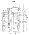
- Fig. 2 is a perspective view of a drive mechanism and linkage system for a plurality of vane arms constructed in accordance with the teachings of the disclosure;
- Fig. 3 is a plan view of two vane arm assemblies constructed in accordance with the teachings of the disclosure
- Fig. 4 is a perspective view of a vane arm constructed in accordance with the teachings of the disclosure.
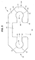
- Fig. 5 is an end view of the vane arm of Fig. 2;
- Fig. 6 is a end view of the vane arm of Fig. 2, but with a vane mounted therein.
- a gas turbine engine constructed in accordance with the teaching of the disclosure is generally referred to by reference numeral 20. While the following detailed description will be made and depicted in conjunction with the specific gas turbine engine identified herein, it is to be understood that the mounting structure of the vane ann assembly can be used in conjunction with any other form or design of gas turbine engine as well.
- the gas turbine engine 20 may include a compressor section 22, a combustion section 24, and a turbine section 26.
- Ambient air is ingested through the intake end 28 of the engine 20 and directed through the compressor section 22.
- the air is compressed within the compressor section 22 and directed through a diffuser 30 after which it is introduced into the combustion section 24 for ignition.
- a plurality of fuel injectors (not shown) inject fuel into the combustion section 24 at predetermined locations to provide for optimum primary, secondary, and tertiary combustions zones within the combustion section 24.
- the hot, rapidly expanding gases of combustion are then expelled through the turbine section 26 and through the exhaust end or nozzle 32 of the engine 20.
- a plurality of blades 38 extend radially outwardly from a rotor 40 mounted to the shaft 34.
- Each of the blades 38 are precisely intermeshed with a plurality of vanes 42 extending radially inwardly from a stator or casing 44.
- each of the stator vanes 42 can be rotated upon its longitudinal axis 46 to thus allow for optimization of the compression ratio and flow rate through the engine 20.
- the angle of attack of the axially flowing compressed air can be changed. This may be desirable based on a variety of engine operating parameters such as compressor rotational speed, air temperature, overall air pressure, etc.
- each stator vane 42 is mounted within a rotatable vane arm 48.
- the vane arm 48 to which the particular vane 42 is mounted is rotated.
- each vane arm 48 is connected to an actuator 50.
- Energization of the actuator 50 causes movement of linkage 51, which in turn causes movement of a synchronization ring 52 extending circumferentially around the engine casing 44.
- movement of the synchronization right 52 causes movement of the vane arms 48, and thus vanes 42.
- actuators and drive mechanisms including, but not limited to, motors, gears, pulleys, linear actuators, solenoids, screw-drives, and the like.
- a number of synchronization rings 52 corresponding to the number of vane stages may be provided, with two rings and stages being depicted in Fig. 2.
- the vane arm 48 is shown to include a mounting head or end 53 from which an actuation lever 54 extends.
- a distal end 56 of the actuation lever 54 includes an aperture 58 to facilitate attachment of the actuation lever 54 to the actuator 50.
- Any type of bolt, fastener, or linkage may be employed in this capacity with a pin 59 being depicted to enable pivotal movement with the synchronization ring 52.
- the mounting head 53 includes a back plate 60 from which first and second claws 62 and 64 extend, thereby defining a vane receiving area or recess 66 as shown in Fig. 5. It is within the vane receiving area 66 that a vane stem 68 of the vane 42 is received as will be described in further detail herein with respect to Fig. 5.
- first and second claws 62 and 64 may be constructed to include four distinct sections including a first section 70 extending downwardly and angularly outwardly (with respect to the orientation of the figures) from the back plate 60, a second section 72 extending downwardly from the first section 70 and substantially perpendicular to the back plate 60, a third section 74 extending downwardly and angularly inwardly from the second section 72, and a fourth section 76 extending from the third section 74 and substantially parallel to the back plate 60.
- the fourth section 76 includes a relatively enlarged end 78, although the ends 78 need not be larger than any other section of the claws 62 and 64 as long as they provide an interference fit with the vane stem 68.
- the vane arm 48 is manufactured by machining metal stock, but it is to be understood that the arm may be made of sheet metal as well, cast metal, or the like.
- the vane receiving area 66 is substantially cross-shaped in sectional view and includes a surge slot 80, first and second lateral slots 82 and 84, and a inlet 86. Both of the lateral slots 82 and 84 include necks 88 having substantially parallel sides 90, 92 leading to a substantially circular or cylindrically shaped void 94.
- the stator vane 42 includes the vane stem 68 extending from a body or foil 98. More specifically, the vane stem 68 includes a trunnion 100, as well as first and second flats 102 and 104. The first and second flats 102 and 104 cooperate with a vane base 106 to form first and second claw slots 108 and 110 for receipt of first and second claws 62 and 64.
- first and second claws 62, 64 form a first mechanism for securing the vane 42 to the vane 48
- a further mechanism for securing the vane 42 to the vane ann 48 is provided by a fastener 112.
- the fastener 112 may be a threaded bolt having a head 114 and threaded stem 116 and may be inserted through the mounting head 53 and into the vane stem 68.
- an aperture I 18 may be provided in the back plate 60 of the mounting head 53, and a threaded aperture 120 may be provided in the vane stem 68. In doing so, it can be seen that the claws combine with the fastener 112 to provide dual retention capabilities.
- a vane arm assembly 122 can be constructed by first sliding the vane stem 68 into the vane arm 48. More specifically, the first and second flats 102 and 104 are positioned so as to be in alignment with first and second lateral slots 82 and 84, and trunnion surface 102 is aligned with the surge slot 80. The vane stem 68 is then slid on to the mounting head 53 until aperture 118 is aligned with aperture 120. In so doing, claws 62 and 64 slide into claw slots 108 and 110. Ends 78 of claws 62 and 64 are designed to ensure a closely toleranced fit with claw slots 108 and 110.
- the threaded fastener 112 can be installed with sufficient torque or preload to ensure assembly 122 is compressed.
- the fastener 112 By rotating the fastener 112 not only is the vane stem 68 brought into tight engagement with the mounting head 53, but the claws 62 and 64 are caused to deflect toward the fastener head 114, thereby crimping the mounting head 53 around the flats 102 and 104.
- the foregoing construction provides a number of advantageous features.
- the vane assembly is compressed under a predetermined preload to ensure a tight fit and second level or means of retention. Moreover, even if the preload on the fastener, or the entire fastener, is lost, the assembly will stay together due to the structural interference between the claws and the flats.
- the vane assembly has enhanced drive capabilities even under high surge or operating loads. More specifically, when trying to drive a vane to a specific angular orientation or hold a vane in such an orientation, the claws may tend to cam or bow away from the claw slots, thereby losing their interference fit. However, by providing a surge slot about the trunnion, when the claws outwardly deflect, the normally loose surge slot will constrict around the trunnion and provide a backup or secondary means for securely gripping the trunnion and ensuring the vane can be driven and/or accurately held during such high loads.
- the surge slot is movable or deformable between first and second positions.
- first position when the vane is operating under normal load conditions, and the claws adequately grip the vane stem, the surge slot is relatively loosely disposed about the vane trunnion.
- second position when the vane is operating under surge or otherwise high loads, the surge slot tightly grips the vane trunnion to enable the vane to be moved to, and held at, the desired angular position.
- the vane assembly of the present disclosure can be made from lighter weight materials such as titanium, than has heretofore been possible. Morever, since the surge slot ensures operability even if the claws begin to cam out of their respective slots, the vane trunnions and vane arm claws can be made shorter and from less material, thereby reducing weight, size, and cost.
- the present disclosure provides a vane ann assembly having enhanced vane retention features and drive capability even under surge conditions or wherein a fastener of the vane arm assembly or preload on the fastener is diminished or entirely lost.
Landscapes
- Engineering & Computer Science (AREA)
- Mechanical Engineering (AREA)
- General Engineering & Computer Science (AREA)
- Structures Of Non-Positive Displacement Pumps (AREA)
- Control Of Turbines (AREA)
- Turbine Rotor Nozzle Sealing (AREA)
Abstract
Description
- The Government has rights in this invention pursuant to Contract No. N00019-02-C-3003.
- The present disclosure generally relates to gas turbine engines and, more particularly, relates to vanes and vane arms used within gas turbine engines.
- Gas turbine engines are widely applied machines for generating power or thrust. Most typically, they are employed on modem aircraft to provide the propulsion necessary for flight. They may also be used onboard such aircraft for power generation in an APU (Auxiliary Power Unit) capacity to provide for onboard heating, cooling, and ventilation, as well as operational power and lighting systems onboard the aircraft within the cockpit, passenger cabin, and the like. They may also be used in land-based applications for generation of electrical power or mechanical horsepower in myriad vehicles and pieces of machinery.
- In a typical gas turbine engine, three main sections are provided, namely, a compressor section, a combustion section, and a turbine section. Within the compressor section, ambient air is ingested, highly compressed, and directed through a downstream diffuser into the combustion section. Within the combustion section, the highly compressed air is mixed with fuel within an annular combustion chamber and burned at extremely high temperatures, generating massive levels of heat energy. Moreover, as opposed to internal combustion engines, wherein the ignition of the fuel is intermittent every two or four strokes of the engine, ignition within a gas turbine engine is continuous, thereby increasing the high power levels attainable by the engine.
- From the combustion section, the extremely hot combustion gases are directed to the turbine section downstream of the combustion chamber. As both the turbine section and the compressor section are mounted on the same shaft assembly, rotation of the turbine blades, upon contact with the rapidly expanding and hot combustion gases, causes the shaft to which they are mounted to rotate and in turn causes the compressor blades, also mounted to the shaft, to rotate and thus complete the engine cycle. The discharge of the rapidly expanding hot gases at high velocities from the turbine causes the engine to generate the aforementioned thrust needed for aircraft operation.
- Typical compressors and turbines include a plurality of blades mounted on the rotor or central shaft of the engine, and a plurality of vanes on an inner engine casing, sometimes referred to as a stator. Within the compressor section, the compression ratio achievable by modem day gas turbine engines is in excess of 40:1. Such compressors can also rotate in excess of 1,000 miles/hr. and ingest in excess of 2,600 lbs/air/sec. These attributes, when combined with the continuous flow and ignition of fuel indicated above, can result in the engine generating in excess of 250,000 hp, with exhaust gases exiting the engine at speeds in excess of 1,000 miles/hr, thereby enabling commercial aircraft to cruise at the slightly less than supersonic speeds at which modem travelers have become accustomed, and military aircraft to travel at Mach speeds necessary in modem warfare.
- However, in order for such engines to operate optimally, the vanes of the compressor section, those extending both from the rotor and the engine casing, must be accurately dimensioned and mounted to ensure the incoming air is compressed as needed and does not simply flow axially through the engine. Moreover, it is often necessary for some of the vanes, typically those mounted on the engine casing, to be movable about a longitudinal axis. More specifically, such vanes are typically provided with a mounting stem or trunnion for connection to a vane arm. The vane arm is mounted so as.to be rotatable and is connected to an actuator, such as a motor or other power source within the aircraft, so as to enable the vanes to rotate when the vane arm rotates.
- In light of the above, one of ordinary skill in the art will readily understand that the mounting structure of the vane arm must be sufficiently robust to withstand the significant forces generated by the compressor section during not only normal operation, but when the engine experiences surge or other transients as well.
- With prior art vane designs, vanes are typically mounted within vane arms using a retention device often referred to as a claw. In other words, the vane arm includes first and second appendages which wrap around the vane trunnion and insert into grooves or slots provided within the vane trunnion. A threaded fastener such as a bolt is then inserted through the vane arm and into the vane trunnion to provide additional attachment. Such a design provides a dual retention feature in that the claws are able to retain the vane in the event that the preload provided by the fastener is lost or when the entire fastener itself becomes dislodged from the vane arm. However, such a design is limited in the load conditions under which it can operate in that the claw arms tend to spread or cam away from the trunnion under high loads thereby causing the assembly to lose its capability for driving the vane to the correct angular orientation.
- In another prior art design, it has therefore been known to provide a vane arm that drives the vane using an interference fit between the trunnion and the vane arm, with a loose fit being provided between another portion of the trunnion and a surge slot of the vane arm. Accordingly, when the vane arm assembly is placed under high loads and the interference fit begins to be lost due to deformation of the vane arm, the deformation causes the loose fitting area between the vane arm and trunion to tighten, thereby providing a secondary mechanism for driving the vane under higher loads. While such a design is effective in this regard, it does not provide,dual retention features in the event of fastener or fastener preload loss, and it requires relatively heavy materials at added expense.
- Within the context of aircraft, it is also important to understand that weight is always at a premium. The lighter the material is, the lighter the engine, and the lighter the engine, the lighter the aircraft will be. This directly translates into less fuel consumption and lower costs of operation. Designers have therefore been required to select materials which are sufficiently robust to withstand the aforementioned loads, while minimizing the weight being added to the aircraft. A still further complicating factor is that of cost. Quite often the materials which are sufficiently robust to withstand the loads encountered by the engine and still meet certain weight requirements, come at costs which make them unacceptable. Alternatively, they come at a cost which makes the overall engine cost more than is desirable.
- In light of the foregoing, it can therefore be seen that a need exists for a vane arm mounting structure with improved retention capabilities even in the situation where fastener preload or the entire fastener are lost, and which can provide a mechanism by which the vane can be driven during both normal loads and surging. Moreover, it would be beneficial if such a design were to be provided wherein relatively inexpensive and light weight materials could be used in the place of materials which have traditionally been required.
- In accordance with one aspect of the disclosure, a variable vane arm is disclosed which may comprise a mounting head and an actuation lever. The mounting head may include a back plate and first and second claws extending away from the mounting head defining a vane receiving area wherein the vane receiving area includes first and second lateral slots and a surge slot. The actuator lever may extend from the mounting head.
- In accordance with another aspect of the disclosure, a variable vane assembly is disclosed which may comprise a vane arm, and a vane connected to the vane arm. The vane arm may include a mounting head and an actuation lever extending from the mounting head wherein the mounting head includes a back plate from which first and second claws extend to thereby define a vane receiving area. The vane receiving area may include a surge slot, flanked by first and second lateral slots. The vane may include a vane stem with the first and second claws of the vane ann extending into first and second grooves in the vane stem. The vane stem may terminate in a vane trunnion which is received in the surge slot.
- In accordance with another aspect of the disclosure, a gas turbine engine having a compressor section, combustion section, and a turbine section is disclosed wherein the compressor section includes a plurality of variable vane arms each comprising a mounting head and an actuation lever. The mounting head may include a back plate and first and second claws extending away from the mounting head and defining a vane receiving area. The vane receiving area may include first and second lateral slots and a surge slot, while the actuation lever may extend from the mounting head.
- In accordance with another aspect of the disclosure, a variable vane assembly is disclosed which may comprise a vane arm, a vane, a first means of securing the vane to the vane arm, a second means of securing the vane to the vane arm, and means for ensuring the vane arm is able to drive the vane in the event that one of the first and second means for securing is inoperable.
- These and other aspects and features of the disclosure will become more apparent upon reading the following detailed description when taken in conjunction with the accompanying drawings.
- Fig. 1 is a sectional view of a gas turbine engine constructed in accordance with the teachings of the disclosure;
- Fig. 2 is a perspective view of a drive mechanism and linkage system for a plurality of vane arms constructed in accordance with the teachings of the disclosure;
- Fig. 3 is a plan view of two vane arm assemblies constructed in accordance with the teachings of the disclosure;
- Fig. 4 is a perspective view of a vane arm constructed in accordance with the teachings of the disclosure;
- Fig. 5 is an end view of the vane arm of Fig. 2; and
- Fig. 6 is a end view of the vane arm of Fig. 2, but with a vane mounted therein.
- While the disclosure is susceptible to various modifications and alternative constructions, certain illustrative embodiments thereof have been shown in the drawings and will be described below in detail. It should be understood, however, that there is no intention to limit the present disclosure to the specific forms disclosed, but on contrary, the intention is to cover all modifications, alternative constructions, and equivalents falling within the spirit and scope of the disclosure as defined by the appended claims.
- Referring now to the drawings, and with specific reference to Fig. 1, a gas turbine engine constructed in accordance with the teaching of the disclosure is generally referred to by
reference numeral 20. While the following detailed description will be made and depicted in conjunction with the specific gas turbine engine identified herein, it is to be understood that the mounting structure of the vane ann assembly can be used in conjunction with any other form or design of gas turbine engine as well. - As depicted herein, the
gas turbine engine 20 may include acompressor section 22, acombustion section 24, and aturbine section 26. Ambient air is ingested through theintake end 28 of theengine 20 and directed through thecompressor section 22. The air is compressed within thecompressor section 22 and directed through adiffuser 30 after which it is introduced into thecombustion section 24 for ignition. A plurality of fuel injectors (not shown) inject fuel into thecombustion section 24 at predetermined locations to provide for optimum primary, secondary, and tertiary combustions zones within thecombustion section 24. The hot, rapidly expanding gases of combustion are then expelled through theturbine section 26 and through the exhaust end ornozzle 32 of theengine 20. As both thecompressor section 24 andturbine section 26 are mounted on acommon shaft 34, when the hot combustion gases are imparted againstturbine blades 36 radiating from theshaft 34, theturbine blades 36 rotate which in turn causes theshaft 34 itself to rotate. Rotation of theshaft 34 in turn causes thecompressor section 22 to rotate, thus perpetuating the engine cycle. - Within the
compressor section 22, a plurality ofblades 38 extend radially outwardly from arotor 40 mounted to theshaft 34. Each of theblades 38 are precisely intermeshed with a plurality ofvanes 42 extending radially inwardly from a stator orcasing 44. Depending upon the operational demands of thegas turbine engine 20, each of thestator vanes 42 can be rotated upon itslongitudinal axis 46 to thus allow for optimization of the compression ratio and flow rate through theengine 20. Through rotation of thestator vanes 42, the angle of attack of the axially flowing compressed air can be changed. This may be desirable based on a variety of engine operating parameters such as compressor rotational speed, air temperature, overall air pressure, etc. - Turning now to Figs. 2 and 3, it will be noted that each
stator vane 42 is mounted within arotatable vane arm 48. When rotation of one of thestator vanes 42 is desired, thevane arm 48 to which theparticular vane 42 is mounted is rotated. To provide the motive force needed for such rotation eachvane arm 48 is connected to anactuator 50. Energization of theactuator 50 causes movement oflinkage 51, which in turn causes movement of asynchronization ring 52 extending circumferentially around theengine casing 44. As each of thevane arms 48 is pivotally connected to thesynchronization ring 52, movement of the synchronization right 52 causes movement of thevane arms 48, and thus vanes 42. Any number of different actuators and drive mechanisms, in addition to those depicted, may be employed, including, but not limited to, motors, gears, pulleys, linear actuators, solenoids, screw-drives, and the like. In addition, a number of synchronization rings 52 corresponding to the number of vane stages may be provided, with two rings and stages being depicted in Fig. 2. - With reference now to Figs. 3 and 4, the
vane arm 48 is shown to include a mounting head or end 53 from which anactuation lever 54 extends. As will be noted, adistal end 56 of theactuation lever 54 includes anaperture 58 to facilitate attachment of theactuation lever 54 to theactuator 50. Any type of bolt, fastener, or linkage may be employed in this capacity with apin 59 being depicted to enable pivotal movement with thesynchronization ring 52. The mountinghead 53 includes aback plate 60 from which first andsecond claws recess 66 as shown in Fig. 5. It is within thevane receiving area 66 that avane stem 68 of thevane 42 is received as will be described in further detail herein with respect to Fig. 5. - With specific reference to first and
second claws first section 70 extending downwardly and angularly outwardly (with respect to the orientation of the figures) from theback plate 60, asecond section 72 extending downwardly from thefirst section 70 and substantially perpendicular to theback plate 60, athird section 74 extending downwardly and angularly inwardly from thesecond section 72, and afourth section 76 extending from thethird section 74 and substantially parallel to theback plate 60. Thefourth section 76 includes a relativelyenlarged end 78, although the ends 78 need not be larger than any other section of theclaws vane stem 68. - In the above described embodiment, the
vane arm 48 is manufactured by machining metal stock, but it is to be understood that the arm may be made of sheet metal as well, cast metal, or the like. Also, in the depicted embodiment, thevane receiving area 66 is substantially cross-shaped in sectional view and includes asurge slot 80, first and secondlateral slots inlet 86. Both of thelateral slots necks 88 having substantiallyparallel sides void 94. - The
stator vane 42 includes the vane stem 68 extending from a body orfoil 98. More specifically, thevane stem 68 includes atrunnion 100, as well as first andsecond flats second flats vane base 106 to form first andsecond claw slots second claws - While the first and
second claws vane 42 to thevane 48, a further mechanism for securing thevane 42 to thevane ann 48 is provided by afastener 112. Thefastener 112 may be a threaded bolt having ahead 114 and threadedstem 116 and may be inserted through the mountinghead 53 and into thevane stem 68. To facilitate this attachment, an aperture I 18 may be provided in theback plate 60 of the mountinghead 53, and a threadedaperture 120 may be provided in thevane stem 68. In doing so, it can be seen that the claws combine with thefastener 112 to provide dual retention capabilities. - Given such structure, a
vane arm assembly 122 can be constructed by first sliding the vane stem 68 into thevane arm 48. More specifically, the first andsecond flats lateral slots trunnion surface 102 is aligned with thesurge slot 80. The vane stem 68 is then slid on to the mountinghead 53 untilaperture 118 is aligned withaperture 120. In so doing,claws claw slots claws claw slots - Once so positioned, the threaded
fastener 112 can be installed with sufficient torque or preload to ensureassembly 122 is compressed. By rotating thefastener 112 not only is the vane stem 68 brought into tight engagement with the mountinghead 53, but theclaws fastener head 114, thereby crimping the mountinghead 53 around theflats - In operation, the foregoing construction provides a number of advantageous features. One, by using a claw design, substantial structural interference between the claws and flats are provided to ensure connection between the vane and vane arm even under the high speeds and centrifugal forces to which these elements are typically subjected.
- Two, by using a threaded fastener, the vane assembly is compressed under a predetermined preload to ensure a tight fit and second level or means of retention. Moreover, even if the preload on the fastener, or the entire fastener, is lost, the assembly will stay together due to the structural interference between the claws and the flats.
- Three, as a result of the surge slot and close tolerances under which it and the vane trunnion are manufactured, the vane assembly has enhanced drive capabilities even under high surge or operating loads. More specifically, when trying to drive a vane to a specific angular orientation or hold a vane in such an orientation, the claws may tend to cam or bow away from the claw slots, thereby losing their interference fit. However, by providing a surge slot about the trunnion, when the claws outwardly deflect, the normally loose surge slot will constrict around the trunnion and provide a backup or secondary means for securely gripping the trunnion and ensuring the vane can be driven and/or accurately held during such high loads. In doing so, it can be seen the surge slot is movable or deformable between first and second positions. In the first position, when the vane is operating under normal load conditions, and the claws adequately grip the vane stem, the surge slot is relatively loosely disposed about the vane trunnion. In the second position, when the vane is operating under surge or otherwise high loads, the surge slot tightly grips the vane trunnion to enable the vane to be moved to, and held at, the desired angular position.
- Four, stemming from all of the above advantages, the vane assembly of the present disclosure can be made from lighter weight materials such as titanium, than has heretofore been possible. Morever, since the surge slot ensures operability even if the claws begin to cam out of their respective slots, the vane trunnions and vane arm claws can be made shorter and from less material, thereby reducing weight, size, and cost.
- Five, using such a design the entire vane assembly can be milled as opposed to broached. Since the vane arm assembly can be milled all over, flexibilities and cost savings are attained over prior designs.
- From the foregoing, it can be appreciated that the present disclosure provides a vane ann assembly having enhanced vane retention features and drive capability even under surge conditions or wherein a fastener of the vane arm assembly or preload on the fastener is diminished or entirely lost.
Claims (27)
- A variable vane arm, comprising:a mounting head having a back plate and first and second claws extending away from the mounting head defining a vane receiving area, the vane receiving area including first and second lateral slots and a surge slot; andan actuation lever extending from the mounting head.
- The variable vane arm of claim 1, wherein the vane receiving area is substantially cross-shaped.
- The variable vane arm of claim 1, wherein the surge slot is flanked by the first and second lateral slots.
- The variable vane arm of claim 1, wherein the mounting head and actuation lever are manufactured from titanium.
- The variable vane arm of claim 1, wherein the back plate includes an aperture.
- The variable vane ann of claim 1, wherein the surge slot is movable between first and second positions.
- The variable vane arm of claim 6, wherein the surge slot is loosely disposed about the vane stem in the first position, and tightly grips the vane stem in the second position.
- A variable vane arm assembly, comprising:a vane arm having a mounting head and an actuation lever extending from the mounting head, the mounting head including a back plate from which first and second claws extend defining a vane receiving area, the vane receiving area including a surge slot flanked by first and second lateral slots; anda vane connected to the vane arm, the vane having a vane stem, the first and second claws of the vane arm extending into first and second grooves in the vane stem, the vane stem terminating in a vane trunnion, the vane trunnion received in the surge slot of the vane arm.
- The variable vane arm assembly of claim 8, further including a fastener connecting the vane arm to the vane.
- The variable vane arm assembly of claim 8, wherein the fastener is a threaded bolt.
- The variable vane arm assembly of claim 10, wherein the threaded fastener applies a predetermined preload to vane assembly.
- The variable vane arm assembly of claim 8, wherein the vane arm is manufactured from titanium.
- The variable vane arm assembly of claim 8, wherein the vane stem further includes first and second flats engaging the first and second claws of the vane arm.
- The variable vane arm assembly of claim 8, wherein the surge slot is movable between a first position loosely disposed about the vane trunnion, and a second position tightly gripping the vane trunnion.
- A gas turbine engine, comprising
a compressor section;
a combustion section;
a turbine section; and
a plurality of variable vane arms mounted within the compressor section, each arm including a mounting head having a back plate and first and second claws extending away from the backplate defining a vane receiving area, the vane receiving area including first and second lateral slots and a surge slot, the variable vane arm further including an actuation lever extending from the mounting head. - The gas turbine engine of claim 15, wherein the vane receiving area is substantially cross-shaped.
- The gas turbine engine of claim 15, wherein the surge slot is flanked by the first and second lateral slots.
- The gas turbine engine of claim 15, wherein the mounting head and actuation lever are manufactured from titanium.
- The gas turbine engine of claim 15, wherein the back plate includes an aperture.
- A variable vane arm assembly, comprising:a vane arm adapted to be secured to an actuator;a vane mounted in the vane arm;a first means for securing the vane to the vane arm;a second means for securing the vane to the vane arm; andmeans for ensuring the vane arm is able to drive the vane in the event one of the first and second means for securing is inoperable.
- The variable vane arm assembly of claim 17, wherein the first means for securing is a claw.
- The variable vane arm assembly of claim 17, wherein the second means for securing is a bolt.
- The variable vane arm assembly of claim 17, wherein the means for ensuring is a surge slot provided within the vane arm.
- The variable vane ann assembly of claim 23, wherein the surge slot is movable between a first position loosely disposed around the vane trunnion and a second position tightly gripping the vane trunnion.
- A method of operating a variable vane assembly, comprising:gripping a vane to a vane arm using first and second claws which wrap around vane stem flats and into vane stem grooves;applying a preload to the vane and vane arm by attaching a threaded fastener therebetween; androtating the vane about a longitudinal axis by rotating the vane arm, a surge slot of the vane arm being loosely disposed about a trunnion of the vane stem when rotating under normal conditions.
- The method of operating a variable vane assembly of claim 25, wherein the vane arm rotates the vane even when the preload is lost.
- The method of operating a variable vane assembly of claim 25, wherein the surge slot drivingly engages the trunnion of the vane stem when rotating under surge loads.
Applications Claiming Priority (2)
| Application Number | Priority Date | Filing Date | Title |
|---|---|---|---|
| US771884 | 2004-02-04 | ||
| US10/771,884 US7011494B2 (en) | 2004-02-04 | 2004-02-04 | Dual retention vane arm |
Publications (3)
| Publication Number | Publication Date |
|---|---|
| EP1561906A2 true EP1561906A2 (en) | 2005-08-10 |
| EP1561906A3 EP1561906A3 (en) | 2009-01-07 |
| EP1561906B1 EP1561906B1 (en) | 2013-03-20 |
Family
ID=34679372
Family Applications (1)
| Application Number | Title | Priority Date | Filing Date |
|---|---|---|---|
| EP04292555A Expired - Lifetime EP1561906B1 (en) | 2004-02-04 | 2004-10-27 | Variable vane arm with dual retention capability |
Country Status (5)
| Country | Link |
|---|---|
| US (1) | US7011494B2 (en) |
| EP (1) | EP1561906B1 (en) |
| AU (1) | AU2004226998A1 (en) |
| CA (1) | CA2486587A1 (en) |
| NO (1) | NO20044661L (en) |
Cited By (3)
| Publication number | Priority date | Publication date | Assignee | Title |
|---|---|---|---|---|
| EP2177771A3 (en) * | 2008-10-15 | 2013-11-13 | United Technologies Corporation | Scalable high pressure compressor variable vane actuation arm |
| EP2481892A3 (en) * | 2011-02-01 | 2013-12-18 | United Technologies Corporation | Gas turbine engine synchronizing ring bumper |
| DE102018202119A1 (en) | 2018-02-12 | 2019-08-14 | MTU Aero Engines AG | Lever connection of a guide vane adjustment for turbomachinery |
Families Citing this family (25)
| Publication number | Priority date | Publication date | Assignee | Title |
|---|---|---|---|---|
| US7871242B2 (en) * | 2007-05-31 | 2011-01-18 | United Technologies Corporation | Single actuator controlled rotational flow balance system |
| US8202043B2 (en) * | 2007-10-15 | 2012-06-19 | United Technologies Corp. | Gas turbine engines and related systems involving variable vanes |
| US8033782B2 (en) * | 2008-01-16 | 2011-10-11 | Elliott Company | Method to prevent brinelling wear of slot and pin assembly |
| US8414248B2 (en) | 2008-12-30 | 2013-04-09 | Rolls-Royce Corporation | Variable geometry vane |
| US8915703B2 (en) * | 2011-07-28 | 2014-12-23 | United Technologies Corporation | Internally actuated inlet guide vane for fan section |
| US10030533B2 (en) * | 2012-09-21 | 2018-07-24 | United Technologies Corporation | Flanged bushing for variable vane |
| US8783119B2 (en) | 2012-09-26 | 2014-07-22 | United Technologies Corporation | Vane arm testing rig |
| WO2014051663A1 (en) * | 2012-09-28 | 2014-04-03 | United Technologies Corporation | Alignment tool for use in a gas turbine engine |
| US10161260B2 (en) | 2013-01-17 | 2018-12-25 | United Technologies Corporation | Vane lever arm for a variable area vane arrangement |
| EP2948634B1 (en) * | 2013-01-24 | 2021-08-25 | Raytheon Technologies Corporation | Gas turbine engine component with angled aperture impingement |
| US10208618B2 (en) * | 2013-02-04 | 2019-02-19 | United Technologies Corporation | Vane arm having a claw |
| EP2971597B1 (en) | 2013-03-13 | 2021-12-29 | Raytheon Technologies Corporation | Machined vane arm of a variable vane actuation system |
| US10253646B2 (en) | 2013-08-22 | 2019-04-09 | United Technologies Corporation | Vane arm assembly |
| US9644491B2 (en) | 2014-06-13 | 2017-05-09 | Pratt & Whitney Canada Corp. | Single bolting flange arrangement for variable guide vane connection |
| US10563670B2 (en) * | 2016-07-29 | 2020-02-18 | Rolls-Royce Corporation | Vane actuation system for a gas turbine engine |
| DE102016224523A1 (en) * | 2016-12-08 | 2018-06-14 | MTU Aero Engines AG | Guide vane adjustment with laterally mounted adjustment lever |
| US10502091B2 (en) * | 2016-12-12 | 2019-12-10 | United Technologies Corporation | Sync ring assembly and associated clevis including a rib |
| US10815818B2 (en) * | 2017-07-18 | 2020-10-27 | Raytheon Technologies Corporation | Variable-pitch vane assembly |
| US10590795B2 (en) * | 2017-10-17 | 2020-03-17 | United Technologies Corporation | Vane arm with tri-wedge circular pocket |
| US10830155B2 (en) | 2018-02-08 | 2020-11-10 | Raytheon Technologies Corporation | Variable vane arm retention feature |
| US10837309B2 (en) | 2019-04-09 | 2020-11-17 | Raytheon Technologies Corporation | Retention clip for variable vane arm |
| US11391174B2 (en) * | 2019-09-17 | 2022-07-19 | Raytheon Technologies Corporation | Vane arm clip for variable stator vanes |
| US11680494B2 (en) * | 2020-02-14 | 2023-06-20 | Raytheon Technologies Corporation | Vane arm torque transfer plate |
| DE202023106055U1 (en) | 2023-10-19 | 2023-11-30 | MTU Aero Engines AG | Lever connection of a guide vane adjustment for turbomachines |
| DE202023106491U1 (en) | 2023-11-07 | 2023-12-13 | MTU Aero Engines AG | Lever connection of a guide vane adjustment for a turbomachine |
Citations (3)
| Publication number | Priority date | Publication date | Assignee | Title |
|---|---|---|---|---|
| US4668165A (en) | 1986-03-27 | 1987-05-26 | The United States Of America As Represented By The Secretary Of The Air Force | Super gripper variable vane arm |
| US4767264A (en) | 1986-10-31 | 1988-08-30 | United Technologies Corporation | Vane lever arm construction |
| EP1010862A2 (en) | 1998-12-16 | 2000-06-21 | General Electric Company | Variable vane seal and washer |
Family Cites Families (10)
| Publication number | Priority date | Publication date | Assignee | Title |
|---|---|---|---|---|
| FR1425074A (en) * | 1965-02-22 | 1966-01-14 | Kolomensky Teplovozostroitelny | Adjustable steering device for radial turbine |
| US4050844A (en) * | 1976-06-01 | 1977-09-27 | United Technologies Corporation | Connection between vane arm and unison ring in variable area stator ring |
| US4755104A (en) * | 1986-04-29 | 1988-07-05 | United Technologies Corporation | Stator vane linkage |
| US4897021A (en) * | 1988-06-02 | 1990-01-30 | United Technologies Corporation | Stator vane asssembly for an axial flow rotary machine |
| US4979874A (en) * | 1989-06-19 | 1990-12-25 | United Technologies Corporation | Variable van drive mechanism |
| US5211537A (en) * | 1992-03-02 | 1993-05-18 | United Technologies Corporation | Compressor vane lock |
| US5517817A (en) * | 1993-10-28 | 1996-05-21 | General Electric Company | Variable area turbine nozzle for turbine engines |
| US5462403A (en) * | 1994-03-21 | 1995-10-31 | United Technologies Corporation | Compressor stator vane assembly |
| US6375419B1 (en) * | 1995-06-02 | 2002-04-23 | United Technologies Corporation | Flow directing element for a turbine engine |
| FR2835295B1 (en) * | 2002-01-29 | 2004-04-16 | Snecma Moteurs | VANE VARIABLE SETTING ANGLE CONTROL DEVICE WITH PINCH CONNECTION FOR TURBOMACHINE COMPRESSOR RECTIFIER |
-
2004
- 2004-02-04 US US10/771,884 patent/US7011494B2/en not_active Expired - Lifetime
- 2004-10-27 EP EP04292555A patent/EP1561906B1/en not_active Expired - Lifetime
- 2004-10-28 NO NO20044661A patent/NO20044661L/en not_active Application Discontinuation
- 2004-11-01 CA CA002486587A patent/CA2486587A1/en not_active Abandoned
- 2004-11-08 AU AU2004226998A patent/AU2004226998A1/en not_active Abandoned
Patent Citations (3)
| Publication number | Priority date | Publication date | Assignee | Title |
|---|---|---|---|---|
| US4668165A (en) | 1986-03-27 | 1987-05-26 | The United States Of America As Represented By The Secretary Of The Air Force | Super gripper variable vane arm |
| US4767264A (en) | 1986-10-31 | 1988-08-30 | United Technologies Corporation | Vane lever arm construction |
| EP1010862A2 (en) | 1998-12-16 | 2000-06-21 | General Electric Company | Variable vane seal and washer |
Cited By (4)
| Publication number | Priority date | Publication date | Assignee | Title |
|---|---|---|---|---|
| EP2177771A3 (en) * | 2008-10-15 | 2013-11-13 | United Technologies Corporation | Scalable high pressure compressor variable vane actuation arm |
| EP2481892A3 (en) * | 2011-02-01 | 2013-12-18 | United Technologies Corporation | Gas turbine engine synchronizing ring bumper |
| US8864450B2 (en) | 2011-02-01 | 2014-10-21 | United Technologies Corporation | Gas turbine engine synchronizing ring bumper |
| DE102018202119A1 (en) | 2018-02-12 | 2019-08-14 | MTU Aero Engines AG | Lever connection of a guide vane adjustment for turbomachinery |
Also Published As
| Publication number | Publication date |
|---|---|
| US7011494B2 (en) | 2006-03-14 |
| CA2486587A1 (en) | 2005-08-04 |
| EP1561906A3 (en) | 2009-01-07 |
| NO20044661L (en) | 2005-08-05 |
| AU2004226998A1 (en) | 2005-08-18 |
| NO20044661D0 (en) | 2004-10-28 |
| EP1561906B1 (en) | 2013-03-20 |
| US20050169741A1 (en) | 2005-08-04 |
Similar Documents
| Publication | Publication Date | Title |
|---|---|---|
| US7011494B2 (en) | Dual retention vane arm | |
| US8215902B2 (en) | Scalable high pressure compressor variable vane actuation arm | |
| US7588415B2 (en) | Synch ring variable vane synchronizing mechanism for inner diameter vane shroud | |
| CN107636295B (en) | Engine intake assembly with selector valve | |
| CN107407207B (en) | Composite engine assembly with coaxial compressor and offset turbine section | |
| US20240417101A1 (en) | Gas turbine engine with clutch assembly | |
| CN107532548B (en) | Compound engine assembly with common inlet | |
| US11506067B2 (en) | Gas turbine engine with clutch assembly | |
| JPH04228805A (en) | Turbine blade outer end attaching structure | |
| EP4006315B1 (en) | Variable orientation guide vane for a gas turbine engine, and method of operating adjacent variable orientation first and second vanes disposed in an annular gas path of a gas turbine engine | |
| US12378898B2 (en) | Windage cover that covers fasteners coupling a ring gear assembly to an output shaft | |
| EP4030039A1 (en) | Inner shroud assembly of a variable vane actuation system for a gas turbine engine, gas turbine engine and method of assembling a variable vane actuation system | |
| EP3502421A1 (en) | A gas turbine engine triple bend finger seal | |
| EP3219931B1 (en) | Vane assembly and corresponding gas turbine engine | |
| US20230304417A1 (en) | Vane arm torque transfer plate | |
| US12264590B2 (en) | Fan assembly for an engine having redundant trunnion retention | |
| EP4552973A1 (en) | Compact aircraft engine with variable pitch propeller and oil transfer ring | |
| FR3033831A1 (en) | ENGINE FOR AIRCRAFT |
Legal Events
| Date | Code | Title | Description |
|---|---|---|---|
| PUAI | Public reference made under article 153(3) epc to a published international application that has entered the european phase |
Free format text: ORIGINAL CODE: 0009012 |
|
| AK | Designated contracting states |
Kind code of ref document: A2 Designated state(s): AT BE BG CH CY CZ DE DK EE ES FI FR GB GR HU IE IT LI LU MC NL PL PT RO SE SI SK TR |
|
| AX | Request for extension of the european patent |
Extension state: AL HR LT LV MK |
|
| PUAL | Search report despatched |
Free format text: ORIGINAL CODE: 0009013 |
|
| AK | Designated contracting states |
Kind code of ref document: A3 Designated state(s): AT BE BG CH CY CZ DE DK EE ES FI FR GB GR HU IE IT LI LU MC NL PL PT RO SE SI SK TR |
|
| AX | Request for extension of the european patent |
Extension state: AL HR LT LV MK |
|
| 17P | Request for examination filed |
Effective date: 20090707 |
|
| AKX | Designation fees paid |
Designated state(s): DE GB |
|
| 17Q | First examination report despatched |
Effective date: 20091016 |
|
| GRAP | Despatch of communication of intention to grant a patent |
Free format text: ORIGINAL CODE: EPIDOSNIGR1 |
|
| GRAS | Grant fee paid |
Free format text: ORIGINAL CODE: EPIDOSNIGR3 |
|
| GRAA | (expected) grant |
Free format text: ORIGINAL CODE: 0009210 |
|
| AK | Designated contracting states |
Kind code of ref document: B1 Designated state(s): DE GB |
|
| REG | Reference to a national code |
Ref country code: GB Ref legal event code: FG4D Ref country code: DE Ref legal event code: R081 Ref document number: 602004041394 Country of ref document: DE Owner name: UNITED TECHNOLOGIES CORP. (N.D.GES.D. STAATES , US Free format text: FORMER OWNER: UNITED TECHNOLOGIES CORP. (N.D.GES.D. STAATES DELAWARE), HARTFORD, CONN., US |
|
| REG | Reference to a national code |
Ref country code: DE Ref legal event code: R096 Ref document number: 602004041394 Country of ref document: DE Effective date: 20130516 |
|
| PLBE | No opposition filed within time limit |
Free format text: ORIGINAL CODE: 0009261 |
|
| STAA | Information on the status of an ep patent application or granted ep patent |
Free format text: STATUS: NO OPPOSITION FILED WITHIN TIME LIMIT |
|
| 26N | No opposition filed |
Effective date: 20140102 |
|
| REG | Reference to a national code |
Ref country code: DE Ref legal event code: R097 Ref document number: 602004041394 Country of ref document: DE Effective date: 20140102 |
|
| REG | Reference to a national code |
Ref country code: DE Ref legal event code: R082 Ref document number: 602004041394 Country of ref document: DE Representative=s name: SCHMITT-NILSON SCHRAUD WAIBEL WOHLFROM PATENTA, DE |
|
| REG | Reference to a national code |
Ref country code: DE Ref legal event code: R082 Ref document number: 602004041394 Country of ref document: DE Representative=s name: SCHMITT-NILSON SCHRAUD WAIBEL WOHLFROM PATENTA, DE Ref country code: DE Ref legal event code: R081 Ref document number: 602004041394 Country of ref document: DE Owner name: UNITED TECHNOLOGIES CORP. (N.D.GES.D. STAATES , US Free format text: FORMER OWNER: UNITED TECHNOLOGIES CORP., HARTFORD, CONN., US |
|
| PGFP | Annual fee paid to national office [announced via postgrant information from national office to epo] |
Ref country code: DE Payment date: 20190918 Year of fee payment: 16 |
|
| REG | Reference to a national code |
Ref country code: DE Ref legal event code: R119 Ref document number: 602004041394 Country of ref document: DE |
|
| PG25 | Lapsed in a contracting state [announced via postgrant information from national office to epo] |
Ref country code: DE Free format text: LAPSE BECAUSE OF NON-PAYMENT OF DUE FEES Effective date: 20210501 |
|
| PGFP | Annual fee paid to national office [announced via postgrant information from national office to epo] |
Ref country code: GB Payment date: 20230920 Year of fee payment: 20 |
|
| REG | Reference to a national code |
Ref country code: GB Ref legal event code: PE20 Expiry date: 20241026 |
|
| PG25 | Lapsed in a contracting state [announced via postgrant information from national office to epo] |
Ref country code: GB Free format text: LAPSE BECAUSE OF EXPIRATION OF PROTECTION Effective date: 20241026 |
|
| PG25 | Lapsed in a contracting state [announced via postgrant information from national office to epo] |
Ref country code: GB Free format text: LAPSE BECAUSE OF EXPIRATION OF PROTECTION Effective date: 20241026 |