EP1561691A1 - Synthetic resin bottle type container - Google Patents
Synthetic resin bottle type container Download PDFInfo
- Publication number
- EP1561691A1 EP1561691A1 EP03758946A EP03758946A EP1561691A1 EP 1561691 A1 EP1561691 A1 EP 1561691A1 EP 03758946 A EP03758946 A EP 03758946A EP 03758946 A EP03758946 A EP 03758946A EP 1561691 A1 EP1561691 A1 EP 1561691A1
- Authority
- EP
- European Patent Office
- Prior art keywords
- groove
- pressure
- shoulder portion
- container
- reduction
- Prior art date
- Legal status (The legal status is an assumption and is not a legal conclusion. Google has not performed a legal analysis and makes no representation as to the accuracy of the status listed.)
- Granted
Links
Images




Classifications
-
- B—PERFORMING OPERATIONS; TRANSPORTING
- B65—CONVEYING; PACKING; STORING; HANDLING THIN OR FILAMENTARY MATERIAL
- B65D—CONTAINERS FOR STORAGE OR TRANSPORT OF ARTICLES OR MATERIALS, e.g. BAGS, BARRELS, BOTTLES, BOXES, CANS, CARTONS, CRATES, DRUMS, JARS, TANKS, HOPPERS, FORWARDING CONTAINERS; ACCESSORIES, CLOSURES, OR FITTINGS THEREFOR; PACKAGING ELEMENTS; PACKAGES
- B65D1/00—Rigid or semi-rigid containers having bodies formed in one piece, e.g. by casting metallic material, by moulding plastics, by blowing vitreous material, by throwing ceramic material, by moulding pulped fibrous material or by deep-drawing operations performed on sheet material
- B65D1/40—Details of walls
- B65D1/42—Reinforcing or strengthening parts or members
-
- B—PERFORMING OPERATIONS; TRANSPORTING
- B65—CONVEYING; PACKING; STORING; HANDLING THIN OR FILAMENTARY MATERIAL
- B65D—CONTAINERS FOR STORAGE OR TRANSPORT OF ARTICLES OR MATERIALS, e.g. BAGS, BARRELS, BOTTLES, BOXES, CANS, CARTONS, CRATES, DRUMS, JARS, TANKS, HOPPERS, FORWARDING CONTAINERS; ACCESSORIES, CLOSURES, OR FITTINGS THEREFOR; PACKAGING ELEMENTS; PACKAGES
- B65D79/00—Kinds or details of packages, not otherwise provided for
- B65D79/005—Packages having deformable parts for indicating or neutralizing internal pressure-variations by other means than venting
- B65D79/008—Packages having deformable parts for indicating or neutralizing internal pressure-variations by other means than venting the deformable part being located in a rigid or semi-rigid container, e.g. in bottles or jars
- B65D79/0084—Packages having deformable parts for indicating or neutralizing internal pressure-variations by other means than venting the deformable part being located in a rigid or semi-rigid container, e.g. in bottles or jars in the sidewall or shoulder part thereof
-
- B—PERFORMING OPERATIONS; TRANSPORTING
- B65—CONVEYING; PACKING; STORING; HANDLING THIN OR FILAMENTARY MATERIAL
- B65D—CONTAINERS FOR STORAGE OR TRANSPORT OF ARTICLES OR MATERIALS, e.g. BAGS, BARRELS, BOTTLES, BOXES, CANS, CARTONS, CRATES, DRUMS, JARS, TANKS, HOPPERS, FORWARDING CONTAINERS; ACCESSORIES, CLOSURES, OR FITTINGS THEREFOR; PACKAGING ELEMENTS; PACKAGES
- B65D1/00—Rigid or semi-rigid containers having bodies formed in one piece, e.g. by casting metallic material, by moulding plastics, by blowing vitreous material, by throwing ceramic material, by moulding pulped fibrous material or by deep-drawing operations performed on sheet material
- B65D1/02—Bottles or similar containers with necks or like restricted apertures, designed for pouring contents
- B65D1/0223—Bottles or similar containers with necks or like restricted apertures, designed for pouring contents characterised by shape
-
- B—PERFORMING OPERATIONS; TRANSPORTING
- B65—CONVEYING; PACKING; STORING; HANDLING THIN OR FILAMENTARY MATERIAL
- B65D—CONTAINERS FOR STORAGE OR TRANSPORT OF ARTICLES OR MATERIALS, e.g. BAGS, BARRELS, BOTTLES, BOXES, CANS, CARTONS, CRATES, DRUMS, JARS, TANKS, HOPPERS, FORWARDING CONTAINERS; ACCESSORIES, CLOSURES, OR FITTINGS THEREFOR; PACKAGING ELEMENTS; PACKAGES
- B65D2501/00—Containers having bodies formed in one piece
- B65D2501/0009—Bottles or similar containers with necks or like restricted apertures designed for pouring contents
- B65D2501/0081—Bottles of non-circular cross-section
Definitions
- the present invention relates to a synthetic resin bottle-type container obtained by molding a synthetic resin, such as polyethylene terephthalate, by biaxial stretch blow molding, and aims at advantageously avoiding occurrence of deformations of the container, particularly deformations on its shoulder portion due to dislocation of pressure reduction absorbing panels.
- a synthetic resin such as polyethylene terephthalate
- synthetic resin containers represented by PET bottles are widely used as containers for storing beverages, seasonings, liquors, detergents, medicines, etc., because they are light in weight and easy to handle, they ensure transparency to provide a refined appearance comparable to glass containers, and they can be obtained at low cost.
- the container body may be provided with at least one groove that is recessed inwards of the container, to thereby define the so-called pressure-reduction absorbing panels.
- the shoulder portion has a relatively poor strength since, from the beginning, the wall at the shoulder portion tends to become thin, and the wall itself does not undergo a sufficient stretching as is the case with the container body portion.
- a blow-molded container provided at its shoulder portion with a stepped portion, and the region extending from the stepped portion to the container body portion has a polyhedral shape as defined by triangular panels (see, for example, Japanese Patent Application Publication No. 06-127542).
- a synthetic resin bottle-type container comprising a shoulder portion continuous with a mouth portion for pouring out contents, and a body portion forms a space for accommodating the contents over an area extending to its bottom wall from said shoulder portion;
- the recess has a width which is substantially the same as that of said groove.
- the recess has a slope inclined from its outer surface toward a bottom of said groove, for preventing shrinkage.
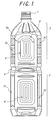
- FIG. 1 illustrates a container according to one embodiment of the present invention.
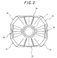
- FIGS. 2, 3 and 4 are side view, plan view and bottom view of the container, respectively.
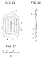
- FIGS. 5a, 5b and 5c are front view, longitudinal-sectional view and cross-sectional view of the pressure-reduction absorbing panel 5, respectively.
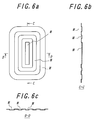
- FIGS. 6a, 6b and 6c are front view, longitudinal-sectional view and cross-sectional view of another pressure-reduction absorbing panel 6, respectively.
- FIGS. 7a, 7b and 7c are front view, longitudinal-sectional view and cross-sectional views of yet another pressure-reduction absorbing panel 7, respectively.
- FIGS. 8a, 8b and 8c are front view, longitudinal-sectional view and cross-sectional views of yet another pressure-reduction absorbing panel 8, respectively.
- FIG. 9 shows the overview of a control container.
- FIG. 10 illustrates a container according to another embodiment of the invention.
- FIGS. 1 to 4 A waisted bottle-type container having a rectangular cross-section according to an embodiment of the invention is shown in FIGS. 1 to 4, wherein reference numeral 1 represents a mouth portion for pouring out the contents, 2 represents a shoulder portion that is continuous with the mouth portion, and 3 represents a body portion forming a space for filling the contents in its region from the shoulder portion 2 to the bottom wall of the container.
- the body portion 3 has a rectangular cross-section, and is integrally formed by a pair of long-side walls 3a placed opposite to each other, and a pair of short-side walls 3b similarly placed opposite to each other, and four corner walls 3c for connecting the adjoining walls 3a and 3b at the corners to enhance the buckling resistance of the container.
- Reference numeral 4 represents a reinforcing waist portion which extends around the body portion 3 to divide it into upper and lower regions
- 5 represents pressure-reduction absorbing panels formed in the upper part of the long-side walls 3a
- 6 represents pressure-reduction absorbing panels formed in the lower part of the long-side walls 3a
- 7 represents pressure-reduction absorbing panels formed in the upper part of the short-side walls 3b
- 8 represents pressure-reduction absorbing panels formed in the lower part of the short-side walls 3b.
- These panels 5 to 8 have their profiles shown in FIGS. 5a, 5b, 5c to FIGS. 8a, 8b, 8c, respectively.
- each panel is defined by grooves M recessed toward the interior of the container so that, when the pressure within the container is reduced, the panels are deflected inwards to thereby prevent the container from deformation.
- Reference numeral 9 represents a recess continuous with the uppermost groove M (i.e., the groove immediately below the shoulder portion) which defines the uppermost border of the pressure-reduction absorbing panel 5, wherein the depth "t" of the recess 9 is greater than that of the groove M (see Fig. 5b).
- FIG. 9 illustrates a control container having the same rectangular cross-section as that of the container shown in FIGS. 1 to 4. Since this type of containers have a larger surface area in its sides containing long-side walls, the shoulder portion has an increased risk of developing local deformation due to the dislocation of the panels upon absorption of the internal pressure reduction. The occurrence of such local deformation causes the yield to be lowered. On the contrary, the container according to the present invention is provided with the recess 9 at the uppermost groove M of each pressure-reduction absorbing panel 5 and the recess 9 has a depth "t" greater than that of the groove M, to increase the local rigidity and thereby avoid a situation wherein the shoulder portion 2 readily undergoes deformation.
- the width of recess 9 is made the same as that of the groove defining the pressure-reduction absorbing panel, in view of the moldability of the container.
- the depth "t" and length of recess 9 may be varied as appropriate, provided that the size of the container and/or the function of the pressure-reduction absorbing panel are not affected.
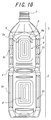
- FIG. 10 illustrates a container representing another embodiment of the invention.
- 1.5 l containers according to the invention as shown in FIGS. 1 to 5 were prepared (the use amount of resin is 55g, the groove defining each pressure-reduction absorbing panel has a depth of 1.5 mm and width of 7mm, and the recess 9 has a depth of 4.5 mm and width of 7 mm), and 1.5 l control containers as shown in Fig. 9 were also prepared (the use amount of resin is 55g, and the groove defining each pressure-reduction absorbing panel has a depth of 1.5 mm and width of 7 mm). These two types of containers were subjected to internal pressure reduction to determine the critical strength to pressure reduction, or the pressure level at which noticeable deformation occurs due to pressure reduction.
- the present invention has been described with reference to the illustrated embodiments on the premise that the container has a rectangular cross-section.
- the present invention is not limited to containers having such a specific configuration, and can also be suitably applied to containers having a circular or polygonal cross-section.
- the capacity of the container is not limited to any specific range, and the invention can also be suitably applied to containers having a capacity that ranges from a volume of as small as 200 ml or 300 ml to a volume larger than 1.5 l , provided that the container has pressure-reduction absorbing panels on its surfaces.
Landscapes
- Engineering & Computer Science (AREA)
- Mechanical Engineering (AREA)
- Ceramic Engineering (AREA)
- Containers Having Bodies Formed In One Piece (AREA)
Abstract
Description
Claims (3)
- A synthetic resin bottle-type container comprising a shoulder portion continuous with a mouth portion through which contents can be poured out, and a body portion forms a space for accommodating the contents over an area extending to its bottom wall from said shoulder portion,said body portion comprising pressure-reduction absorbing panels defined by at least one groove that projects inwards of said container;said at least one groove comprising a groove for said pressure-reduction absorbing panel which is situated immediately below said shoulder portion, said groove being provided with a recess extending along said groove and having a depth larger than that of the groove.said at least one groove comprising a groove for said pressure-reduction absorbing panel which is situated immediately below said shoulder portion, said groove being provided with a recess extending along said groove and having a depth larger than that of the groove.
- The bottle-type container according to Claim 1, wherein said recess has a width which is substantially the same as that of said groove.
- The bottle-type container according to Claim 1 or 2, wherein said recess has a slope inclined from its outer surface toward a bottom of said groove, for preventing shrinkage.
Applications Claiming Priority (3)
| Application Number | Priority Date | Filing Date | Title |
|---|---|---|---|
| JP2002312779 | 2002-10-28 | ||
| JP2002312779A JP3983646B2 (en) | 2002-10-28 | 2002-10-28 | Synthetic resin bottle type container |
| PCT/JP2003/013720 WO2004037658A1 (en) | 2002-10-28 | 2003-10-27 | Synthetic resin bottle type container |
Publications (3)
| Publication Number | Publication Date |
|---|---|
| EP1561691A1 true EP1561691A1 (en) | 2005-08-10 |
| EP1561691A4 EP1561691A4 (en) | 2007-08-15 |
| EP1561691B1 EP1561691B1 (en) | 2013-04-03 |
Family
ID=32171149
Family Applications (1)
| Application Number | Title | Priority Date | Filing Date |
|---|---|---|---|
| EP03758946A Expired - Lifetime EP1561691B1 (en) | 2002-10-28 | 2003-10-27 | Synthetic resin bottle type container |
Country Status (7)
| Country | Link |
|---|---|
| US (1) | US7165693B2 (en) |
| EP (1) | EP1561691B1 (en) |
| JP (1) | JP3983646B2 (en) |
| KR (1) | KR100706855B1 (en) |
| CN (1) | CN100340456C (en) |
| TW (1) | TWI230675B (en) |
| WO (1) | WO2004037658A1 (en) |
Cited By (5)
| Publication number | Priority date | Publication date | Assignee | Title |
|---|---|---|---|---|
| WO2007032545A3 (en) * | 2005-09-16 | 2007-07-12 | Coca Cola Co | Plastic bottle |
| US7472798B2 (en) * | 2006-08-15 | 2009-01-06 | Ball Corporation | Polygonal hour-glass hot-fillable bottle |
| WO2011011183A1 (en) * | 2009-07-20 | 2011-01-27 | Graham Packaging Company, L.P. | Container having compound flexible panels |
| EP2468649A1 (en) * | 2005-08-31 | 2012-06-27 | Yoshino Kogyosho Co., Ltd. | Synthetic rectangular bottle |
| AU2012202318B2 (en) * | 2005-08-31 | 2013-05-16 | Yoshino Kogyosho Co., Ltd. | Synthetic resin bottle |
Families Citing this family (35)
| Publication number | Priority date | Publication date | Assignee | Title |
|---|---|---|---|---|
| US7882971B2 (en) * | 2002-12-05 | 2011-02-08 | Graham Packaging Company, L.P. | Rectangular container with vacuum panels |
| US9896233B2 (en) | 2002-12-05 | 2018-02-20 | Graham Packaging Company, L.P. | Rectangular container having a vertically extending groove |
| US20050139572A1 (en) * | 2003-12-29 | 2005-06-30 | Pedmo Marc A. | Plastic container |
| US20070187354A1 (en) * | 2004-04-16 | 2007-08-16 | Yoshino Kogyosho Co., Ltd. | Large bottle-shaped container having substantially rectangular cross section |
| USD544354S1 (en) * | 2005-02-02 | 2007-06-12 | Irwin Industrial Tool Company | Bottle |
| KR101230677B1 (en) * | 2005-02-18 | 2013-02-07 | 도요 세이칸 가부시키가이샤 | Container |
| US7748551B2 (en) * | 2005-02-18 | 2010-07-06 | Ball Corporation | Hot fill container with restricted corner radius vacuum panels |
| FR2887238B1 (en) * | 2005-06-21 | 2007-09-28 | Jean Tristan Outreman | PROCESS FOR HOT-FILLING A THIN-WALL CONTAINER AND FILLED CONTAINER THUS OBTAINED |
| JP5029859B2 (en) * | 2005-06-30 | 2012-09-19 | 株式会社吉野工業所 | Synthetic resin housing |
| JP4936239B2 (en) * | 2005-07-29 | 2012-05-23 | 株式会社吉野工業所 | Synthetic resin housing |
| US7568588B2 (en) * | 2005-08-16 | 2009-08-04 | Graham Packaging Company, L.P. | Container with contour |
| US7455189B2 (en) * | 2005-08-22 | 2008-11-25 | Amcor Limited | Rectangular hot-filled container |
| JP5014636B2 (en) * | 2006-01-24 | 2012-08-29 | 株式会社吉野工業所 | Square bottle |
| US7661548B2 (en) * | 2006-01-25 | 2010-02-16 | The Quaker Oats Company | Hot-fill container with improved top-load performance |
| JP4893092B2 (en) * | 2006-04-28 | 2012-03-07 | 大日本印刷株式会社 | Plastic container |
| JP4756504B2 (en) * | 2006-05-31 | 2011-08-24 | 株式会社吉野工業所 | Synthetic plastic square bottle |
| JP4962942B2 (en) * | 2006-06-29 | 2012-06-27 | 株式会社吉野工業所 | Synthetic resin housing |
| US7874442B2 (en) * | 2006-10-06 | 2011-01-25 | Amcor Limited | Hot-fill plastic container with ribs and grip |
| FR2907763B1 (en) * | 2006-10-27 | 2010-12-10 | Sidel Participations | CONTAINER, IN PARTICULAR BOTTLE, THERMOPLASTIC MATERIAL |
| JP4818881B2 (en) * | 2006-10-31 | 2011-11-16 | 株式会社吉野工業所 | Square bottle |
| USD600129S1 (en) * | 2007-01-26 | 2009-09-15 | Sidel Participations | Bottle |
| WO2008130996A1 (en) * | 2007-04-16 | 2008-10-30 | Constar International, Inc. | Container having vacuum compensation elements |
| US7832583B2 (en) * | 2007-10-16 | 2010-11-16 | Graham Packaging Company, L.P. | Hot-fillable container and method of making |
| US8567622B2 (en) * | 2009-08-27 | 2013-10-29 | Graham Packaging Company, L.P. | Dome shaped hot-fill container |
| FR2949756B1 (en) * | 2009-09-04 | 2012-02-03 | Sidel Participations | CONTAINER WITH GROOVED FACETS. |
| US8602237B2 (en) * | 2009-10-06 | 2013-12-10 | Graham Packaging Company, L.P. | Pasteurizable and hot-fillable blow molded plastic container |
| CA2790892A1 (en) * | 2010-04-20 | 2011-10-27 | Nampak Plastics Europe Limited | Plastics container |
| USD669358S1 (en) * | 2010-10-18 | 2012-10-23 | Amcor Limited | Container |
| JP5584929B2 (en) * | 2010-12-17 | 2014-09-10 | サントリーホールディングス株式会社 | Resin container |
| US8556097B2 (en) * | 2011-02-16 | 2013-10-15 | Amcor Limited | Container having vacuum panel with balanced vacuum and pressure response |
| USD717174S1 (en) * | 2012-01-11 | 2014-11-11 | The Clorox Company | Bottle |
| JP6732410B2 (en) * | 2015-04-30 | 2020-07-29 | 株式会社吉野工業所 | Synthetic resin container |
| JP7162517B2 (en) * | 2018-12-18 | 2022-10-28 | 株式会社吉野工業所 | square bottle |
| DE102019131426A1 (en) * | 2019-11-21 | 2021-05-27 | E-PROPLAST-GmbH | Container for holding liquids |
| WO2021154209A1 (en) * | 2020-01-28 | 2021-08-05 | Amcor Rigid Packaging Usa, Llc | Method of controlling vacuum and pressure within a thermoplastic container |
Family Cites Families (21)
| Publication number | Priority date | Publication date | Assignee | Title |
|---|---|---|---|---|
| FR1449600A (en) * | 1964-09-14 | 1966-05-06 | Fr Des Laboratoires Labaz Soc | Improvements to flexible material bottles, especially for medicinal products |
| US5238129A (en) * | 1985-07-30 | 1993-08-24 | Yoshino Kogyosho Co., Ltd. | Container having ribs and collapse panels |
| JPH0315320A (en) | 1989-06-10 | 1991-01-23 | Uchiyama Green Kk | Vessel for cultivation of tree and cultivation method using the same |
| JPH0644806Y2 (en) * | 1989-07-10 | 1994-11-16 | 株式会社吉野工業所 | Bottle made of synthetic resin |
| CN1022820C (en) * | 1989-09-29 | 1993-11-24 | 株式会社吉野工业所 | Jar formed with biaxial stretching blow moulding |
| US5178289A (en) * | 1992-02-26 | 1993-01-12 | Continental Pet Technologies, Inc. | Panel design for a hot-fillable container |
| JPH061213U (en) * | 1992-06-10 | 1994-01-11 | 株式会社吉野工業所 | Bottle made of synthetic resin |
| JPH061213A (en) * | 1992-06-17 | 1994-01-11 | Mitsubishi Motors Corp | Driving method of pump / motor for braking energy regeneration |
| JPH06127542A (en) * | 1992-10-16 | 1994-05-10 | Dainippon Printing Co Ltd | Large biaxially stretched blow molding container |
| US5337909A (en) * | 1993-02-12 | 1994-08-16 | Hoover Universal, Inc. | Hot fill plastic container having a radial reinforcement rib |
| JP3378099B2 (en) | 1994-11-16 | 2003-02-17 | 三菱樹脂株式会社 | Plastic bottle |
| JP2839012B2 (en) * | 1996-06-05 | 1998-12-16 | 株式会社吉野工業所 | Synthetic resin bottle |
| JPH09328115A (en) * | 1996-06-11 | 1997-12-22 | Mitsubishi Plastics Ind Ltd | Plastic square bottle |
| JPH1058527A (en) * | 1996-08-23 | 1998-03-03 | Toyo Seikan Kaisha Ltd | Biaxially oriented blow-molded container |
| JPH11180428A (en) * | 1997-12-22 | 1999-07-06 | Hokkai Can Co Ltd | Synthetic resin container |
| US6164474A (en) * | 1998-11-20 | 2000-12-26 | Crown Cork & Seal Technologies Corporation | Bottle with integrated grip portion |
| SK287003B6 (en) * | 1999-02-25 | 2009-09-07 | David Murray Melrose | A container having pressure responsive panels |
| JP3942803B2 (en) * | 2000-05-17 | 2007-07-11 | 株式会社吉野工業所 | Bottle vacuum absorption panel |
| AU2002211764A1 (en) * | 2000-10-19 | 2002-04-29 | Graham Packaging Company, L.P. | Hot fillable container having separate rigid grips and flex panels |
| JP4044282B2 (en) * | 2000-12-26 | 2008-02-06 | 三菱樹脂株式会社 | Bottle container |
| JP2003063516A (en) * | 2001-08-21 | 2003-03-05 | Toyo Seikan Kaisha Ltd | Synthetic resin container |
-
2002
- 2002-10-28 JP JP2002312779A patent/JP3983646B2/en not_active Expired - Fee Related
-
2003
- 2003-10-27 KR KR1020057007249A patent/KR100706855B1/en not_active Expired - Fee Related
- 2003-10-27 WO PCT/JP2003/013720 patent/WO2004037658A1/en not_active Ceased
- 2003-10-27 EP EP03758946A patent/EP1561691B1/en not_active Expired - Lifetime
- 2003-10-27 CN CNB2003801021908A patent/CN100340456C/en not_active Expired - Fee Related
- 2003-10-27 US US10/531,995 patent/US7165693B2/en not_active Expired - Lifetime
- 2003-10-28 TW TW092129867A patent/TWI230675B/en not_active IP Right Cessation
Cited By (7)
| Publication number | Priority date | Publication date | Assignee | Title |
|---|---|---|---|---|
| EP2468649A1 (en) * | 2005-08-31 | 2012-06-27 | Yoshino Kogyosho Co., Ltd. | Synthetic rectangular bottle |
| AU2012202318B2 (en) * | 2005-08-31 | 2013-05-16 | Yoshino Kogyosho Co., Ltd. | Synthetic resin bottle |
| WO2007032545A3 (en) * | 2005-09-16 | 2007-07-12 | Coca Cola Co | Plastic bottle |
| EA012547B1 (en) * | 2005-09-16 | 2009-10-30 | Дзе Кока-Кола Компани | Plastic bottle |
| US7472798B2 (en) * | 2006-08-15 | 2009-01-06 | Ball Corporation | Polygonal hour-glass hot-fillable bottle |
| WO2011011183A1 (en) * | 2009-07-20 | 2011-01-27 | Graham Packaging Company, L.P. | Container having compound flexible panels |
| US9102434B2 (en) | 2009-07-20 | 2015-08-11 | Graham Packaging Company, L.P. | Container having compound flexible panels |
Also Published As
| Publication number | Publication date |
|---|---|
| EP1561691A4 (en) | 2007-08-15 |
| KR20050061567A (en) | 2005-06-22 |
| CN100340456C (en) | 2007-10-03 |
| JP2004142820A (en) | 2004-05-20 |
| JP3983646B2 (en) | 2007-09-26 |
| US20060054587A1 (en) | 2006-03-16 |
| TWI230675B (en) | 2005-04-11 |
| TW200415078A (en) | 2004-08-16 |
| US7165693B2 (en) | 2007-01-23 |
| WO2004037658A1 (en) | 2004-05-06 |
| KR100706855B1 (en) | 2007-04-13 |
| CN1708432A (en) | 2005-12-14 |
| EP1561691B1 (en) | 2013-04-03 |
Similar Documents
| Publication | Publication Date | Title |
|---|---|---|
| US7165693B2 (en) | Synthetic resin bottle-type container with improved deformation resistance | |
| CA2461681C (en) | Pinch grip type bottle-shaped container | |
| EP1574439B1 (en) | Synthetic resin container having improved shape stability | |
| CA2640373C (en) | Hot-fillable container and method of making | |
| US7874442B2 (en) | Hot-fill plastic container with ribs and grip | |
| US20050067370A1 (en) | Bottle container | |
| TW200835627A (en) | Bottle with narrow portion | |
| JP3050587U (en) | Biaxial stretch blow molded container | |
| JP3513539B2 (en) | Synthetic resin bottle | |
| JP3544706B2 (en) | Biaxial stretch blow molded container | |
| JP3050588U (en) | Biaxial stretch blow molded container | |
| JP3608420B2 (en) | Plastic container | |
| JP2003104347A (en) | Waisted container made of synthetic resin | |
| JP7651932B2 (en) | Synthetic resin container | |
| JP3560368B2 (en) | Biaxial stretch blow molded container | |
| JPH10236450A (en) | Parallelopiped plastic bottle | |
| JP4986436B2 (en) | Synthetic resin bottle-type container with a vacuum absorbing panel | |
| JPH07205258A (en) | Biaxially oriented blow molding vessel | |
| JP2000309329A (en) | Polygonal container made of synthetic resin | |
| JP2024056446A (en) | Plastic containers | |
| CN112793933A (en) | Container with a lid | |
| JPH09272522A (en) | Plastic bottle |
Legal Events
| Date | Code | Title | Description |
|---|---|---|---|
| PUAI | Public reference made under article 153(3) epc to a published international application that has entered the european phase |
Free format text: ORIGINAL CODE: 0009012 |
|
| 17P | Request for examination filed |
Effective date: 20050502 |
|
| AK | Designated contracting states |
Kind code of ref document: A1 Designated state(s): AT BE BG CH CY CZ DE DK EE ES FI FR GB GR HU IE IT LI LU MC NL PT RO SE SI SK TR |
|
| AX | Request for extension of the european patent |
Extension state: AL LT LV MK |
|
| DAX | Request for extension of the european patent (deleted) | ||
| RBV | Designated contracting states (corrected) |
Designated state(s): DE FR GB |
|
| A4 | Supplementary search report drawn up and despatched |
Effective date: 20070718 |
|
| 17Q | First examination report despatched |
Effective date: 20080408 |
|
| RIC1 | Information provided on ipc code assigned before grant |
Ipc: B65D 79/00 20060101AFI20120926BHEP |
|
| REG | Reference to a national code |
Ref country code: DE Ref legal event code: R079 Ref document number: 60343673 Country of ref document: DE Free format text: PREVIOUS MAIN CLASS: B65D0001020000 Ipc: B65D0079000000 |
|
| GRAP | Despatch of communication of intention to grant a patent |
Free format text: ORIGINAL CODE: EPIDOSNIGR1 |
|
| RIC1 | Information provided on ipc code assigned before grant |
Ipc: B65D 1/02 20060101AFI20121023BHEP |
|
| RIC1 | Information provided on ipc code assigned before grant |
Ipc: B65D 79/00 20060101AFI20121101BHEP |
|
| GRAS | Grant fee paid |
Free format text: ORIGINAL CODE: EPIDOSNIGR3 |
|
| GRAA | (expected) grant |
Free format text: ORIGINAL CODE: 0009210 |
|
| AK | Designated contracting states |
Kind code of ref document: B1 Designated state(s): DE FR GB |
|
| REG | Reference to a national code |
Ref country code: GB Ref legal event code: FG4D |
|
| REG | Reference to a national code |
Ref country code: DE Ref legal event code: R096 Ref document number: 60343673 Country of ref document: DE Effective date: 20130529 |
|
| PLBE | No opposition filed within time limit |
Free format text: ORIGINAL CODE: 0009261 |
|
| STAA | Information on the status of an ep patent application or granted ep patent |
Free format text: STATUS: NO OPPOSITION FILED WITHIN TIME LIMIT |
|
| 26N | No opposition filed |
Effective date: 20140106 |
|
| REG | Reference to a national code |
Ref country code: DE Ref legal event code: R097 Ref document number: 60343673 Country of ref document: DE Effective date: 20140106 |
|
| REG | Reference to a national code |
Ref country code: FR Ref legal event code: PLFP Year of fee payment: 13 |
|
| REG | Reference to a national code |
Ref country code: FR Ref legal event code: PLFP Year of fee payment: 14 |
|
| REG | Reference to a national code |
Ref country code: FR Ref legal event code: PLFP Year of fee payment: 15 |
|
| REG | Reference to a national code |
Ref country code: FR Ref legal event code: PLFP Year of fee payment: 16 |
|
| PGFP | Annual fee paid to national office [announced via postgrant information from national office to epo] |
Ref country code: FR Payment date: 20180913 Year of fee payment: 16 |
|
| PGFP | Annual fee paid to national office [announced via postgrant information from national office to epo] |
Ref country code: DE Payment date: 20181016 Year of fee payment: 16 |
|
| PGFP | Annual fee paid to national office [announced via postgrant information from national office to epo] |
Ref country code: GB Payment date: 20181024 Year of fee payment: 16 |
|
| REG | Reference to a national code |
Ref country code: DE Ref legal event code: R119 Ref document number: 60343673 Country of ref document: DE |
|
| PG25 | Lapsed in a contracting state [announced via postgrant information from national office to epo] |
Ref country code: DE Free format text: LAPSE BECAUSE OF NON-PAYMENT OF DUE FEES Effective date: 20200501 |
|
| GBPC | Gb: european patent ceased through non-payment of renewal fee |
Effective date: 20191027 |
|
| PG25 | Lapsed in a contracting state [announced via postgrant information from national office to epo] |
Ref country code: FR Free format text: LAPSE BECAUSE OF NON-PAYMENT OF DUE FEES Effective date: 20191031 Ref country code: GB Free format text: LAPSE BECAUSE OF NON-PAYMENT OF DUE FEES Effective date: 20191027 |