EP1561632A2 - System for generation and distribution of energy on board motor vehicles - Google Patents
System for generation and distribution of energy on board motor vehicles Download PDFInfo
- Publication number
- EP1561632A2 EP1561632A2 EP20050100677 EP05100677A EP1561632A2 EP 1561632 A2 EP1561632 A2 EP 1561632A2 EP 20050100677 EP20050100677 EP 20050100677 EP 05100677 A EP05100677 A EP 05100677A EP 1561632 A2 EP1561632 A2 EP 1561632A2
- Authority
- EP
- European Patent Office
- Prior art keywords
- line
- coupled
- generators
- distribution network
- mgm
- Prior art date
- Legal status (The legal status is an assumption and is not a legal conclusion. Google has not performed a legal analysis and makes no representation as to the accuracy of the status listed.)
- Withdrawn
Links
- 239000011159 matrix material Substances 0.000 claims abstract description 30
- 230000005611 electricity Effects 0.000 claims abstract description 28
- 239000000446 fuel Substances 0.000 claims abstract description 11
- 239000002828 fuel tank Substances 0.000 claims abstract description 4
- 238000002485 combustion reaction Methods 0.000 claims description 28
- 230000000694 effects Effects 0.000 claims description 6
- 239000007789 gas Substances 0.000 claims description 6
- 238000005474 detonation Methods 0.000 claims description 4
- 238000006243 chemical reaction Methods 0.000 claims description 2
- 239000003153 chemical reaction reagent Substances 0.000 claims description 2
- 238000004200 deflagration Methods 0.000 claims description 2
- 230000000873 masking effect Effects 0.000 claims description 2
- 239000000126 substance Substances 0.000 claims description 2
- 239000004020 conductor Substances 0.000 description 3
- 239000007858 starting material Substances 0.000 description 3
- UFHFLCQGNIYNRP-UHFFFAOYSA-N Hydrogen Chemical compound [H][H] UFHFLCQGNIYNRP-UHFFFAOYSA-N 0.000 description 2
- 238000010586 diagram Methods 0.000 description 2
- 239000001257 hydrogen Substances 0.000 description 2
- 229910052739 hydrogen Inorganic materials 0.000 description 2
- 150000002500 ions Chemical class 0.000 description 2
- 239000003915 liquefied petroleum gas Substances 0.000 description 2
- VNWKTOKETHGBQD-UHFFFAOYSA-N methane Chemical compound C VNWKTOKETHGBQD-UHFFFAOYSA-N 0.000 description 2
- 239000002253 acid Substances 0.000 description 1
- 238000004378 air conditioning Methods 0.000 description 1
- 238000013459 approach Methods 0.000 description 1
- QVGXLLKOCUKJST-UHFFFAOYSA-N atomic oxygen Chemical compound [O] QVGXLLKOCUKJST-UHFFFAOYSA-N 0.000 description 1
- 238000010276 construction Methods 0.000 description 1
- 230000008878 coupling Effects 0.000 description 1
- 238000010168 coupling process Methods 0.000 description 1
- 238000005859 coupling reaction Methods 0.000 description 1
- 239000003344 environmental pollutant Substances 0.000 description 1
- 239000012530 fluid Substances 0.000 description 1
- 238000009434 installation Methods 0.000 description 1
- 238000006386 neutralization reaction Methods 0.000 description 1
- 230000003287 optical effect Effects 0.000 description 1
- 239000001301 oxygen Substances 0.000 description 1
- 229910052760 oxygen Inorganic materials 0.000 description 1
- 231100000719 pollutant Toxicity 0.000 description 1
- 238000010248 power generation Methods 0.000 description 1
- 239000000725 suspension Substances 0.000 description 1
- 230000000699 topical effect Effects 0.000 description 1
- 230000005612 types of electricity Effects 0.000 description 1
- 238000009423 ventilation Methods 0.000 description 1
Images


Classifications
-
- B—PERFORMING OPERATIONS; TRANSPORTING
- B60—VEHICLES IN GENERAL
- B60L—PROPULSION OF ELECTRICALLY-PROPELLED VEHICLES; SUPPLYING ELECTRIC POWER FOR AUXILIARY EQUIPMENT OF ELECTRICALLY-PROPELLED VEHICLES; ELECTRODYNAMIC BRAKE SYSTEMS FOR VEHICLES IN GENERAL; MAGNETIC SUSPENSION OR LEVITATION FOR VEHICLES; MONITORING OPERATING VARIABLES OF ELECTRICALLY-PROPELLED VEHICLES; ELECTRIC SAFETY DEVICES FOR ELECTRICALLY-PROPELLED VEHICLES
- B60L1/00—Supplying electric power to auxiliary equipment of vehicles
-
- H—ELECTRICITY
- H01—ELECTRIC ELEMENTS
- H01M—PROCESSES OR MEANS, e.g. BATTERIES, FOR THE DIRECT CONVERSION OF CHEMICAL ENERGY INTO ELECTRICAL ENERGY
- H01M10/00—Secondary cells; Manufacture thereof
- H01M10/06—Lead-acid accumulators
-
- H—ELECTRICITY
- H01—ELECTRIC ELEMENTS
- H01M—PROCESSES OR MEANS, e.g. BATTERIES, FOR THE DIRECT CONVERSION OF CHEMICAL ENERGY INTO ELECTRICAL ENERGY
- H01M10/00—Secondary cells; Manufacture thereof
- H01M10/42—Methods or arrangements for servicing or maintenance of secondary cells or secondary half-cells
-
- H—ELECTRICITY
- H02—GENERATION; CONVERSION OR DISTRIBUTION OF ELECTRIC POWER
- H02K—DYNAMO-ELECTRIC MACHINES
- H02K44/00—Machines in which the dynamo-electric interaction between a plasma or flow of conductive liquid or of fluid-borne conductive or magnetic particles and a coil system or magnetic field converts energy of mass flow into electrical energy or vice versa
- H02K44/28—Association of MHD generators with conventional generators
-
- Y—GENERAL TAGGING OF NEW TECHNOLOGICAL DEVELOPMENTS; GENERAL TAGGING OF CROSS-SECTIONAL TECHNOLOGIES SPANNING OVER SEVERAL SECTIONS OF THE IPC; TECHNICAL SUBJECTS COVERED BY FORMER USPC CROSS-REFERENCE ART COLLECTIONS [XRACs] AND DIGESTS
- Y02—TECHNOLOGIES OR APPLICATIONS FOR MITIGATION OR ADAPTATION AGAINST CLIMATE CHANGE
- Y02E—REDUCTION OF GREENHOUSE GAS [GHG] EMISSIONS, RELATED TO ENERGY GENERATION, TRANSMISSION OR DISTRIBUTION
- Y02E60/00—Enabling technologies; Technologies with a potential or indirect contribution to GHG emissions mitigation
- Y02E60/10—Energy storage using batteries
-
- Y—GENERAL TAGGING OF NEW TECHNOLOGICAL DEVELOPMENTS; GENERAL TAGGING OF CROSS-SECTIONAL TECHNOLOGIES SPANNING OVER SEVERAL SECTIONS OF THE IPC; TECHNICAL SUBJECTS COVERED BY FORMER USPC CROSS-REFERENCE ART COLLECTIONS [XRACs] AND DIGESTS
- Y02—TECHNOLOGIES OR APPLICATIONS FOR MITIGATION OR ADAPTATION AGAINST CLIMATE CHANGE
- Y02T—CLIMATE CHANGE MITIGATION TECHNOLOGIES RELATED TO TRANSPORTATION
- Y02T10/00—Road transport of goods or passengers
- Y02T10/60—Other road transportation technologies with climate change mitigation effect
- Y02T10/64—Electric machine technologies in electromobility
Definitions
- the subject of the present invention is in general, innovative architecture for systems of generating and distributing energy on board motor vehicles.
- the invention relates to a system for generation and distribution of energy on board a motor vehicle provided with a propulsion unit, at least one fuel tank, at least one distribution network or line for electrical energy, means for generation of electrical energy connected to the said at least one distribution network or line; and a plurality of selectively activatable electrical consumer devices or apparatus, connected or connectable to the said at least one distribution network or line.
- the architecture of the system most currently used in the automobile field for generation of mechanical and electrical energy envisages the use of a propulsion unit, typically an internal combustion engine, with an associated electrical starter motor, an electricity generator driven to rotate by the propulsion unit, and at least one accumulator battery, typically of the lead-acid type.
- a propulsion unit typically an internal combustion engine
- an electricity generator driven to rotate by the propulsion unit
- at least one accumulator battery typically of the lead-acid type.
- the on-board electrical consumer devices and apparatus such as, for example, the engine control system, the lighting installation, the ABS system etc, are supplied with electrical energy rendered available by the generator and/or the accumulator battery.
- the electricity generator typically a three-phase alternator with associated bridge rectifier circuit
- the propulsion unit is driven to rotate by the propulsion unit.
- This creates problems in that this arrangement does not easily allow optimisation of the control and management strategies for operation of the propulsion unit for the purpose of reducing fuel consumption and the emission of pollutants, a decoupling of the function of the propulsion unit from that of the electrical apparatus or devices being, on the other hand desirable for this purpose.
- This problem is more important if it is considered that in the future a significant increase in the demand for electrical power on board vehicles from the current 2-3kw to levels of the order of 10kw are envisaged.
- One object of the present invention is to propose innovative architectures for systems for generation and distribution of energy on board motor vehicles, which allows the achievement of improved efficiency both in terms of generation yield and in terms of management of the electrical users and simplification of the implementation of new functions.
- the said electrical energy generator means comprise at least one battery or matrix of microcombustor electricity generators, connected to the said at least one fuel tank, and a supervision and control unit associated with the said at least one battery or matrix of microcombustor electricity generators and coupled to the said at least one distribution network or line and arranged to control the operation of the said battery or matrix of generators in predetermined modes as a function of the electrical power required or consumed by the said at least one distribution network or line.
- Micro-scale combustors and their applications are described for instance in A. Carlos Fernandez-Pello, "Micro-Power Generation Using Combustors: Issues and Approaches", Topical Review at the Twenty-Ninth International Symposium on Combustion, July 21-26, 2002, Sapporo, Japan.
- the propulsion unit of the motor vehicle is an internal combustion engine and the said at least one battery or matrix of microcombustor generators has an exhaust manifold selectively connectable to this internal combustion engine in such a way that the exhaust gases from the microcombustors of the said battery or matrix of generators are able to cause starting of this internal combustion engine.
- the conventional electric starter motor associated with the internal combustion engine it is therefore conveniently possible to do away with the conventional electric starter motor associated with the internal combustion engine.
- the said at least one battery or matrix of microcombustor generators conveniently has an exhaust manifold selectively connectable in a controlled manner to the said heat exchanger.
- An exhaust manifold or duct of the said at least one battery or matrix of microcombustor generators may conveniently be coupled to a magnetohydrodynamic effect electricity generator, for example of the type described in earlier European patent application 04028552.0 in the name of the same Applicant, the electrical output of which is coupled to the said at least one electrical energy distribution network or line of on board the motor vehicle.
- the or each batter of microcombustor generators may in general comprise an array of M x N microcombustors disposed in M rows and N columns and electrically connected together for example in series by columns and in parallel by rows.
- Such a battery or matrix of generators is conveniently associated with a supervision and control unit (management controller) arranged to determine an electrical output with predetermined current and voltage characteristics and which can be modulated through a suitable selection of the number of generators which are made active.
- the electrical output can for example be varied by steps of 2 volts by varying the number of activated microgenerators.
- this motor can be supplied with electrical energy generated by the said at least one battery or matrix of microcombustor electricity generators, for example of the type known from the above cited preceding patent applications.
- the propulsion unit E is, for example, an internal combustion engine of traditional type, supplied with fuel F from a tank R.
- This fuel may be, for example, petrol, diesel, methane or liquefied petroleum gas (LPG) or even hydrogen.
- the system comprises two electrical energy distribution lines at different voltages (for example at 42V d.c. and 12V d.c. respectively) and, in particular, one line including two conductors 1 and 2 of which the second is connected to ground GND and the second line including the conductor 2 and a further conductor indicated 3.
- a plurality of selectively activatable electrical consumer devices or apparatus are connected to the distribution lines 1-2 and 2-3.
- these devices or apparatus comprise an electric starter motor M, a system for the direct control of valves or injectors DVC, an air conditioning, ventilation and heater system HVAC, devices XBW for control of the functions in a so-called "by-wire” manner, and possible others connected to the line 1-2.
- the system shown in Figure 1 comprises (at least) one battery or matrix MGM of microcombustor electricity generators, supplied with a combustion supporter, for example oxygen or air, and with a fuel which may be the fuel F coming directly from the tank R or a derived fuel, for example hydrogen obtained from a reformer FR supplied at its input with the fuel F.
- a combustion supporter for example oxygen or air
- a fuel which may be the fuel F coming directly from the tank R or a derived fuel, for example hydrogen obtained from a reformer FR supplied at its input with the fuel F.
- the matrix MGM of electricity generators may include, for example, a plurality of microcombustor generators of a type known from the patent application mentioned above, as well as the type described in the earlier European patent application 04026127.3, again in the name of the same Applicant.
- the microcombustors or at least groups of these are connected together fluidically in parallel, and the associated converter means which provide electrical energy at the output are conveniently connected together in series.
- Other modes of fluid and/or electrical connection are however possible.
- an electronic control unit EPMS which supervises the management and generation of energy.
- the control unit EPMS is moreover connected to the lines 1-2 and 2-3.
- This unit which can be formed using microprocessors, is conveniently arranged to control the functioning of the battery or matrix MGM of generators in predetermined modes as a function of the instantaneous electrical power requirements for the power consumed by the distribution lines and the devices and apparatus connected to it.
- the unit EPMS is in particular arranged to modulate the electrical power generated by the matrix MGM of generators via a modulation of the number of microcombustor electricity generators activated from time to time, and/or by modulating the rate of flow of fuel F and/or of combustion supporter supplied to the matrix MGM via controlled solenoid valve devices such as those indicated ELV.
- the motor vehicle can be formed without need for the traditional on-board electricity generator (alternator) and the associated accumulator battery.
- the system makes it possible to de-couple the function of the propulsion unit E from that of the electricalteils. This makes it possible to optimise the control and management strategies for operation of the engine E, with consequent reduction in fuel consumption and polluting emissions.
- Figure 2 is shown a variant embodiment of a system according to the invention.
- the same or substantially equivalent parts and components as those already described have again been attributed the same alphabetic or numeric reference symbols.
- the battery or matrix of generators MGM has an exhaust manifold EM1 coupled to the internal combustion engine E, for example by means of a solenoid valve device ELV1 controlled by the unit EPMS in such a way that the exhaust gases from the microcombustors of the battery or matrix MGM of generators, or at least one of them, are capable of causing starting of the internal combustion engine.
- the battery or matrix MGM of generators may conveniently have an exhaust manifold such as that indicated EM2 in Figure 2, selectively connectable to the said heat exchanger, for example by means of a solenoid valve device ELV2, likewise controlled by the unit EPMS.
- EM2 exhaust manifold
- ELV2 solenoid valve device
- FIG 3 there is schematically illustrated a further variant embodiment of a system according to the invention.
- the same or substantially corresponding elements or components as those described already have again been attributed the same alphanumeric references used previously.
- an exhaust manifold EME of the internal combustion engine E is coupled to the inlet of a magnetohydrodynamic effect electricity generator MHDG, the electrical output of which is coupled to at least one of the distribution lines 1-2 and 2-3.
- the magnetohydrodynamic effect electricity generator MHDG can be of one of the types described in any of the patent documents cited in the introduction to the present description, or of other type known per se.
- the exhaust manifold EEM of the engine E can be coupled to the input of a high kinetic energy positive ion electricity generator, the positive ions of which are obtained from the plasma produced by the combustion reaction and separated from the electrons for example by means of a neutralisation or masking grille.
- the exhaust manifold EEM of the engine E can be coupled to the input of an electricity generator operating in a detonation, impulsed or continuous regime, or a magnetic suspension rotary generator operating by combustion in a deflagration or detonation regime, or still further, to the input of an electricity generator of the magnetic micropiston type, or to a generator operating in a confined combustion regime in which the control of the reagents is obtained in cavities which contribute to "selection" of the kinetics of the chemical and physical reaction.
- FIG 4 there is shown a variant embodiment of a system according to the invention for use in a motor vehicle the propulsion of which can be achieved by means of an electric machine PM fed with the electrical energy generated by a plurality of batteries or microcombustor electricity generator matrices indicated MGM1-MGMn.
- the electric propulsion machine PM can be used as the sole vehicle propulsion unit (electric vehicle) or as an alternative to an internal combustion engine of traditional type (hybrid vehicle).
Landscapes
- Engineering & Computer Science (AREA)
- Power Engineering (AREA)
- Transportation (AREA)
- Mechanical Engineering (AREA)
- Control Of Eletrric Generators (AREA)
- Electric Propulsion And Braking For Vehicles (AREA)
- Output Control And Ontrol Of Special Type Engine (AREA)
Abstract
Description
- The subject of the present invention, is in general, innovative architecture for systems of generating and distributing energy on board motor vehicles.
- More specifically, the invention relates to a system for generation and distribution of energy on board a motor vehicle provided with
a propulsion unit,
at least one fuel tank,
at least one distribution network or line for electrical energy,
means for generation of electrical energy connected to the said at least one distribution network or line; and
a plurality of selectively activatable electrical consumer devices or apparatus, connected or connectable to the said at least one distribution network or line. - The architecture of the system most currently used in the automobile field for generation of mechanical and electrical energy envisages the use of a propulsion unit, typically an internal combustion engine, with an associated electrical starter motor, an electricity generator driven to rotate by the propulsion unit, and at least one accumulator battery, typically of the lead-acid type. The on-board electrical consumer devices and apparatus, such as, for example, the engine control system, the lighting installation, the ABS system etc, are supplied with electrical energy rendered available by the generator and/or the accumulator battery.
- In this architecture the electricity generator, typically a three-phase alternator with associated bridge rectifier circuit, is driven to rotate by the propulsion unit. This creates problems in that this arrangement does not easily allow optimisation of the control and management strategies for operation of the propulsion unit for the purpose of reducing fuel consumption and the emission of pollutants, a decoupling of the function of the propulsion unit from that of the electrical apparatus or devices being, on the other hand desirable for this purpose. This problem is more important if it is considered that in the future a significant increase in the demand for electrical power on board vehicles from the current 2-3kw to levels of the order of 10kw are envisaged.
- One object of the present invention is to propose innovative architectures for systems for generation and distribution of energy on board motor vehicles, which allows the achievement of improved efficiency both in terms of generation yield and in terms of management of the electrical users and simplification of the implementation of new functions.
- This, and other objects, are achieved according to the invention with a system for generation and distribution of energy on board a motor vehicle, of the type specified above, characterised in that the said electrical energy generator means comprise
at least one battery or matrix of microcombustor electricity generators, connected to the said at least one fuel tank, and
a supervision and control unit associated with the said at least one battery or matrix of microcombustor electricity generators and coupled to the said at least one distribution network or line and arranged to control the operation of the said battery or matrix of generators in predetermined modes as a function of the electrical power required or consumed by the said at least one distribution network or line. - Micro-scale combustors and their applications are described for instance in A. Carlos Fernandez-Pello, "Micro-Power Generation Using Combustors: Issues and Approaches", Topical Review at the Twenty-Ninth International Symposium on Combustion, July 21-26, 2002, Sapporo, Japan.
- In one embodiment the propulsion unit of the motor vehicle is an internal combustion engine and the said at least one battery or matrix of microcombustor generators has an exhaust manifold selectively connectable to this internal combustion engine in such a way that the exhaust gases from the microcombustors of the said battery or matrix of generators are able to cause starting of this internal combustion engine. In such a system it is therefore conveniently possible to do away with the conventional electric starter motor associated with the internal combustion engine.
- In one implementation of the invention on board a motor vehicle which is provided with a heater unit including a heat exchanger of gas/air type, the said at least one battery or matrix of microcombustor generators conveniently has an exhaust manifold selectively connectable in a controlled manner to the said heat exchanger.
- An exhaust manifold or duct of the said at least one battery or matrix of microcombustor generators may conveniently be coupled to a magnetohydrodynamic effect electricity generator, for example of the type described in earlier European patent application 04028552.0 in the name of the same Applicant, the electrical output of which is coupled to the said at least one electrical energy distribution network or line of on board the motor vehicle.
- Other types of electricity generators suitable for the purpose are those described for example in European patent applications 04030126.9 and 04029814.3 or the thermophotovoltaic effect generators according to Italian patent application T02002A000375, all in the name of the same Applicant.
- The or each batter of microcombustor generators may in general comprise an array of M x N microcombustors disposed in M rows and N columns and electrically connected together for example in series by columns and in parallel by rows.
- Such a battery or matrix of generators is conveniently associated with a supervision and control unit (management controller) arranged to determine an electrical output with predetermined current and voltage characteristics and which can be modulated through a suitable selection of the number of generators which are made active. The electrical output can for example be varied by steps of 2 volts by varying the number of activated microgenerators.
- In an alternative specific embodiment for a motor vehicle the propulsion unit of which is an electric machine, this motor can be supplied with electrical energy generated by the said at least one battery or matrix of microcombustor electricity generators, for example of the type known from the above cited preceding patent applications.
- Further characteristics and advantages of the invention will become apparent from the following detailed description which is given purely by way of non-limitative example, with reference to the attached drawings, in which:
- Figure 1 is a block diagram representation of the structure of a first system for generation and distribution of energy on board a motor vehicle according to the invention; and
- Figures from 2 to 4 are block diagram representations of variant embodiments of the system according to the invention.
-
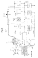
- In Figure 1 the propulsion unit of the motor vehicle provided with a system for generation and distribution of electrical energy according to the invention is indicated E.
- The propulsion unit E is, for example, an internal combustion engine of traditional type, supplied with fuel F from a tank R. This fuel may be, for example, petrol, diesel, methane or liquefied petroleum gas (LPG) or even hydrogen.
- In the exemplary embodiment illustrated the system comprises two electrical energy distribution lines at different voltages (for example at 42V d.c. and 12V d.c. respectively) and, in particular, one line including two conductors 1 and 2 of which the second is connected to ground GND and the second line including the conductor 2 and a further conductor indicated 3.
- A plurality of selectively activatable electrical consumer devices or apparatus are connected to the distribution lines 1-2 and 2-3.
- In the exemplary representation of Figure 1 these devices or apparatus comprise an electric starter motor M, a system for the direct control of valves or injectors DVC, an air conditioning, ventilation and heater system HVAC, devices XBW for control of the functions in a so-called "by-wire" manner, and possible others connected to the line 1-2.
- Other devices, such as on-board indicator instrument DI, an engine control unit ECU, lights or lamps and other optical indicators L, systems VDC for the control of vehicle dynamics etc are similarly associated with the distribution line 2-3.
- The system shown in Figure 1 comprises (at least) one battery or matrix MGM of microcombustor electricity generators, supplied with a combustion supporter, for example oxygen or air, and with a fuel which may be the fuel F coming directly from the tank R or a derived fuel, for example hydrogen obtained from a reformer FR supplied at its input with the fuel F.
- The matrix MGM of electricity generators may include, for example, a plurality of microcombustor generators of a type known from the patent application mentioned above, as well as the type described in the earlier European patent application 04026127.3, again in the name of the same Applicant.
- In the matrix MGM the microcombustors or at least groups of these, are connected together fluidically in parallel, and the associated converter means which provide electrical energy at the output are conveniently connected together in series. Other modes of fluid and/or electrical connection are however possible.
- Associated with the electricity generator matrix MGM is an electronic control unit EPMS which supervises the management and generation of energy.
- The control unit EPMS is moreover connected to the lines 1-2 and 2-3. This unit, which can be formed using microprocessors, is conveniently arranged to control the functioning of the battery or matrix MGM of generators in predetermined modes as a function of the instantaneous electrical power requirements for the power consumed by the distribution lines and the devices and apparatus connected to it.
- The unit EPMS is in particular arranged to modulate the electrical power generated by the matrix MGM of generators via a modulation of the number of microcombustor electricity generators activated from time to time, and/or by modulating the rate of flow of fuel F and/or of combustion supporter supplied to the matrix MGM via controlled solenoid valve devices such as those indicated ELV.
- As can be immediately appreciated by observing Figure 1, with the above-described system the motor vehicle can be formed without need for the traditional on-board electricity generator (alternator) and the associated accumulator battery.
- Moreover, the system makes it possible to de-couple the function of the propulsion unit E from that of the electrical utilisers. This makes it possible to optimise the control and management strategies for operation of the engine E, with consequent reduction in fuel consumption and polluting emissions.
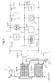
- In Figure 2 is shown a variant embodiment of a system according to the invention. In this Figure the same or substantially equivalent parts and components as those already described have again been attributed the same alphabetic or numeric reference symbols.
- In the embodiment of Figure 2 the battery or matrix of generators MGM has an exhaust manifold EM1 coupled to the internal combustion engine E, for example by means of a solenoid valve device ELV1 controlled by the unit EPMS in such a way that the exhaust gases from the microcombustors of the battery or matrix MGM of generators, or at least one of them, are capable of causing starting of the internal combustion engine.
- For a motor vehicle provided with a heater unit HU including a heat exchanger of gas/air type, of type known per se, the battery or matrix MGM of generators may conveniently have an exhaust manifold such as that indicated EM2 in Figure 2, selectively connectable to the said heat exchanger, for example by means of a solenoid valve device ELV2, likewise controlled by the unit EPMS. This arrangement, graphically shown in Figure 2, can however be adopted even in a system of the type according to Figure 1 described above.
- In Figure 3 there is schematically illustrated a further variant embodiment of a system according to the invention. In this Figure the same or substantially corresponding elements or components as those described already have again been attributed the same alphanumeric references used previously.
- In the variant according to Figure 3, an exhaust manifold EME of the internal combustion engine E is coupled to the inlet of a magnetohydrodynamic effect electricity generator MHDG, the electrical output of which is coupled to at least one of the distribution lines 1-2 and 2-3.
- The magnetohydrodynamic effect electricity generator MHDG can be of one of the types described in any of the patent documents cited in the introduction to the present description, or of other type known per se.
- The coupling of the exhaust manifold of the engine E to a magnetohydrodynamic effect electricity generator can also be achieved in a system of the type illustrated with reference to Figure 1 described above.
- As an alternative to the arrangement just described with reference to Figure 3, the exhaust manifold EEM of the engine E can be coupled to the input of a high kinetic energy positive ion electricity generator, the positive ions of which are obtained from the plasma produced by the combustion reaction and separated from the electrons for example by means of a neutralisation or masking grille.
- In a further alternative the exhaust manifold EEM of the engine E can be coupled to the input of an electricity generator operating in a detonation, impulsed or continuous regime, or a magnetic suspension rotary generator operating by combustion in a deflagration or detonation regime, or still further, to the input of an electricity generator of the magnetic micropiston type, or to a generator operating in a confined combustion regime in which the control of the reagents is obtained in cavities which contribute to "selection" of the kinetics of the chemical and physical reaction.
- In Figure 4 there is shown a variant embodiment of a system according to the invention for use in a motor vehicle the propulsion of which can be achieved by means of an electric machine PM fed with the electrical energy generated by a plurality of batteries or microcombustor electricity generator matrices indicated MGM1-MGMn.
- In Figure 4, also, the components already described have again been allocated to the same alphanumeric reference symbols.
- The electric propulsion machine PM can be used as the sole vehicle propulsion unit (electric vehicle) or as an alternative to an internal combustion engine of traditional type (hybrid vehicle).
- Naturally, the principle of the invention remaining the same, the embodiments and details of construction can be widely varied with respect to what has been described and illustrated purely by way of non-limitative example, without by this departing from the ambit of the invention as defined in the annexed claims.
Claims (11)
- A system for generation and distribution of energy on board a motor vehicle provided with
a propulsion unit (E; PM);
at least one tank (R) for fuel (F);
at least one distribution network or line for electric energy (1-2; 2-3);
electrical energy generation means (MGM) connected to the said at least one distribution network or line (1-2; 2-3); and
a plurality of selectively activatable electrical utiliser devices or apparatus (M, DVC, HVAC, DI, etc) connected or connectable to the said at least one distribution network or line (1-2; 2-3);
the system being characterised in that the said electrical energy generator means comprise
at least one battery or matrix of microcombustor electricity generators (MGM; MGM1-MGMn) connected to the said at least one fuel tank (R), and
a supervision and control unit (EPM) associated with the said at least one battery or matrix of microcombustor electricity generators (MGM, MGM1-MGMn) and coupled to the said at least one distribution network or line (1-2; 2-3) and arranged to control the operation of the said battery or matrix of generators (MGM; MGM1-MGMn) in a predetermined manner as a function of the electrical power required or consumed by the said at least one line or network (1-2; 2-3). - A system according to Claim 1, in which the said propulsion unit is an internal combustion engine (E) and in which the said at least one battery or matrix of microcombustor generators (MGM; MGM1-MGMn) has an exhaust manifold (EM1) selectively connectable to the internal combustion engine (E) in such a way that the exhaust gases from the microcombustors of the battery or matrix of generators (MGM; MGM1-MGMn) are able to cause starting of the said internal combustion engine (E).
- A system according to Claim 1 or Claim 2, for a motor vehicle provided with a heater unit (HU) including a heat exchanger of the gas/air type, and the said at least one battery or matrix of generators (MGM; MGM1-MGMn) has an exhaust manifold (EM; EM2) selectively connectable in a controlled manner to the said heat exchanger.
- A system according to any preceding Claim, in which the said propulsion unit is an internal combustion engine (E) having an exhaust manifold or duct (EEM) coupled to a magnetohydrodynamic effect electric generator (MHDG) the electricity output of which is coupled to the said at least one distribution network or line (1-2).
- A system according to any of Claims from 1 to 3, in which the said propulsion unit is an internal combustion engine (E) having an exhaust manifold or duct in (EEM) coupled to a high kinetic energy positive ion electricity generator obtained by masking with a grille the electrons produced by a combustion reaction, the electrical output of which is coupled to the said at least one distribution network or line (1-2).
- A system according to any of Claims from 1 to 3, in which the said propulsion unit is an internal combustion engine (E) having an exhaust manifold or duct (EEM) coupled to an electricity generator operating in a detonation, impulsed or continuous regime, the electrical output of which is coupled to the said at least one distribution network or line (1-2).
- A system according to any of Claims 1 to 3, in which the said propulsion unit is an internal combustion engine (E) having an exhaust manifold or duct (EEM) coupled to an electricity generator of the magnetically suspended rotary type, operating by combustion in a deflagration or detonation regime, the electric output of which is coupled to the said at least one distribution network or line (1-2).
- A system according to any of Claims from 1 to 3, in which the said propulsion unit is an internal combustion engine (E) having an exhaust manifold or duct (EEM) coupled to a magnetic micropiston electricity generator the electrical output of which is coupled to the said at least one distribution network or line (1-2).
- A system according to any of Claims from 1 to 3, in which the said propulsion unit is an internal combustion engine (E) having an exhaust manifold or duct (EEM) coupled to an electricity generator operating in a confined combustion regime in which the control of the reagents is achieved in cavities which contribute to the selection of the chemical and physical reaction kinetics, the electrical output of which is coupled to the said at least one distribution network or line (1-2).
- A system according to Claim 1, in which the said propulsion unit is an electric machine (PM) supplied with the electrical energy generated by the said at least one battery or matrix of microcombustor electricity generators (MGM1-MGMn).
- A system according to any preceding Claim, in which the said battery or matrix of microcombustor generators (MGM; MGM1-MGMn) comprises M x N generators disposed in M rows and N columns with M and N equal or different from one another, groups of the said generators being connected electrically together in parallel or in series.
Applications Claiming Priority (2)
| Application Number | Priority Date | Filing Date | Title |
|---|---|---|---|
| ITTO20040054 | 2004-02-04 | ||
| ITTO20040054 ITTO20040054A1 (en) | 2004-02-04 | 2004-02-04 | INNOVATIVE ARCHITECTURES OF ENERGY GENERATION AND DISTRIBUTION SYSTEMS ON BOARD MOTOR VEHICLES |
Publications (2)
| Publication Number | Publication Date |
|---|---|
| EP1561632A2 true EP1561632A2 (en) | 2005-08-10 |
| EP1561632A3 EP1561632A3 (en) | 2008-02-20 |
Family
ID=34674593
Family Applications (1)
| Application Number | Title | Priority Date | Filing Date |
|---|---|---|---|
| EP20050100677 Withdrawn EP1561632A3 (en) | 2004-02-04 | 2005-02-01 | System for generation and distribution of energy on board motor vehicles |
Country Status (5)
| Country | Link |
|---|---|
| US (2) | US7385309B2 (en) |
| EP (1) | EP1561632A3 (en) |
| CN (1) | CN1655424A (en) |
| IT (1) | ITTO20040054A1 (en) |
| RU (1) | RU2005102668A (en) |
Families Citing this family (4)
| Publication number | Priority date | Publication date | Assignee | Title |
|---|---|---|---|---|
| ITTO20040054A1 (en) * | 2004-02-04 | 2004-05-04 | Fiat Ricerche | INNOVATIVE ARCHITECTURES OF ENERGY GENERATION AND DISTRIBUTION SYSTEMS ON BOARD MOTOR VEHICLES |
| US7378749B2 (en) * | 2005-10-26 | 2008-05-27 | Moore Donald O | Electrical generator system |
| CN108988575B (en) * | 2018-05-30 | 2020-07-03 | 国网新源控股有限公司回龙分公司 | High-reliability generator set |
| WO2020061102A1 (en) | 2018-09-19 | 2020-03-26 | Inverge, Llc. | Door threshold |
Family Cites Families (39)
| Publication number | Priority date | Publication date | Assignee | Title |
|---|---|---|---|---|
| US3273336A (en) * | 1961-05-29 | 1966-09-20 | Robert P Kidwell | Apparatus for controlling conductive fluids |
| US3638054A (en) * | 1969-04-04 | 1972-01-25 | Richard F Honigsbaum | Alternating current electrofluid dynamic energy conversion device |
| US3585421A (en) * | 1969-07-15 | 1971-06-15 | Gen Motors Corp | Electrogasdynamic power device for a reciprocating engine |
| US4300512A (en) * | 1979-03-05 | 1981-11-17 | Franz Dennis L | MHD Engine |
| US4597363A (en) * | 1981-02-27 | 1986-07-01 | Melvin Emelock | Hydrogen generator for motor vehicle |
| US4704571A (en) * | 1985-06-24 | 1987-11-03 | Siemens Aktiengesellschaft | Arrangement for recovering power loss of an internal combustion engine |
| JP2540898B2 (en) * | 1987-12-30 | 1996-10-09 | いすゞ自動車株式会社 | Air blast system for hot storage |
| US5313123A (en) * | 1992-11-23 | 1994-05-17 | Leonid Simuni | Automobile having the magnetohydrodynamic engine |
| JP3094745B2 (en) * | 1993-09-24 | 2000-10-03 | トヨタ自動車株式会社 | Hybrid vehicle power generation control device |
| US5637935A (en) * | 1994-03-24 | 1997-06-10 | Martin Marietta Energy Systems, Inc. | Double-duct liquid metal magnetohydrodynamic engine |
| PT101481B (en) * | 1994-03-30 | 1996-12-31 | Leopoldo Alberto De Sa Pinto S | HYBRID CAR WITH 2 ENGINES: ONE ELECTRIC AND ONE TO JET WHICH, WHEN OPERATING, CHARGES THE ELECTRIC MOTOR BATTERY |
| JP2587202B2 (en) * | 1994-08-22 | 1997-03-05 | 本田技研工業株式会社 | Power generation control device for hybrid vehicle |
| JP3450906B2 (en) * | 1994-08-25 | 2003-09-29 | 本田技研工業株式会社 | Charge control device for electric vehicles |
| CN1055574C (en) * | 1996-03-06 | 2000-08-16 | 杨泰和 | Engine-driven battery auxiliary charging system with automatic monitoring and operation |
| US6105697A (en) * | 1996-04-01 | 2000-08-22 | Weaver; Winstead B. | Hybrid turbine-electric motor system |
| US5708312A (en) * | 1996-11-19 | 1998-01-13 | Rosen Motors, L.P. | Magnetic bearing system including a control system for a flywheel and method for operating same |
| US6111332A (en) * | 1998-02-03 | 2000-08-29 | The Regents Of The University Of California | Combined passive bearing element/generator motor |
| JP3381613B2 (en) * | 1998-03-20 | 2003-03-04 | 日産自動車株式会社 | Drive control device for hybrid vehicle |
| US5945749A (en) * | 1998-06-10 | 1999-08-31 | Westinghouse Air Brake Company | On-board electrical power generator operated by vibration or compressed air |
| US6554088B2 (en) * | 1998-09-14 | 2003-04-29 | Paice Corporation | Hybrid vehicles |
| US6029921A (en) * | 1998-10-29 | 2000-02-29 | Johnson; John R. | Centerpull paper product |
| US6414400B1 (en) * | 1999-02-03 | 2002-07-02 | Coleman Powermate, Inc. | Small engine driven generator |
| FR2792259B1 (en) * | 1999-04-15 | 2001-06-15 | Valeo Thermique Moteur Sa | COOLING DEVICE FOR ELECTRIC VEHICLE WITH FUEL CELL |
| US6385972B1 (en) * | 1999-08-30 | 2002-05-14 | Oscar Lee Fellows | Thermoacoustic resonator |
| AU3085901A (en) * | 2000-01-07 | 2001-07-24 | University Of Southern California | Microcombustor and combustion-based thermoelectric microgenerator |
| US6242873B1 (en) * | 2000-01-31 | 2001-06-05 | Azure Dynamics Inc. | Method and apparatus for adaptive hybrid vehicle control |
| US6601560B1 (en) * | 2000-03-27 | 2003-08-05 | Avl List Gmbh | Method for starting and operating an internal combustion engine |
| JP3676184B2 (en) * | 2000-04-13 | 2005-07-27 | 矢崎総業株式会社 | Vehicle power supply |
| US6746789B1 (en) * | 2000-06-13 | 2004-06-08 | Hydrogenics Corporation | Catalytic humidifier and heater for the fuel stream of a fuel cell |
| US6275004B1 (en) * | 2000-09-11 | 2001-08-14 | General Motors Corporation | System for battery module balancing via variable voltage DC-DC converter in a hybrid-electric powertrain |
| JP3624831B2 (en) * | 2000-12-28 | 2005-03-02 | 株式会社デンソー | Vehicle power supply device and engine drive regulation support device |
| US20030070850A1 (en) * | 2001-02-16 | 2003-04-17 | Cellex Power Products, Inc. | Hybrid power supply apparatus for battery replacement applications |
| US6690560B2 (en) * | 2001-04-24 | 2004-02-10 | Denso Corporation | Electrical load controller and vehicle air conditioner using the same |
| JP3820977B2 (en) * | 2001-12-13 | 2006-09-13 | トヨタ自動車株式会社 | Hybrid system heat storage device |
| WO2003057529A2 (en) * | 2002-01-08 | 2003-07-17 | Hypercar, Inc. | Advanced composite hybrid-electric vehicle |
| ITTO20020375A1 (en) | 2002-05-07 | 2003-11-07 | Fiat Ricerche | ,, ELECTRICITY MICROGENERATOR ,, |
| DE20306735U1 (en) * | 2003-04-30 | 2003-07-03 | Huang, Kuo-Lin, Liu-Chiao, Chia-I | Electric generator for vehicle has housing with tubular wall having inlet end section for connecting source of exhaust gas, which causes rotation of primary shaft to which a rotor is coupled |
| US7087329B2 (en) * | 2003-11-19 | 2006-08-08 | Utc Fuel Cells, Llc | Electric storage augmentation of fuel cell system transient response |
| ITTO20040054A1 (en) * | 2004-02-04 | 2004-05-04 | Fiat Ricerche | INNOVATIVE ARCHITECTURES OF ENERGY GENERATION AND DISTRIBUTION SYSTEMS ON BOARD MOTOR VEHICLES |
-
2004
- 2004-02-04 IT ITTO20040054 patent/ITTO20040054A1/en unknown
-
2005
- 2005-02-01 EP EP20050100677 patent/EP1561632A3/en not_active Withdrawn
- 2005-02-03 RU RU2005102668/11A patent/RU2005102668A/en not_active Application Discontinuation
- 2005-02-03 US US11/048,905 patent/US7385309B2/en not_active Expired - Fee Related
- 2005-02-04 CN CNA2005100542612A patent/CN1655424A/en active Pending
-
2008
- 2008-05-09 US US12/118,072 patent/US7960856B2/en not_active Expired - Fee Related
Non-Patent Citations (1)
| Title |
|---|
| A. CARLOS FERNANDEZ-PELLO: "Micro-Power Generation Using Combustors: Issues and Approaches", TOPICAL REVIEW AT THE TWENTY-NINTH INTERNATIONAL SYMPOSIUM ON COMBUSTION, 21 July 2002 (2002-07-21) |
Also Published As
| Publication number | Publication date |
|---|---|
| CN1655424A (en) | 2005-08-17 |
| US20080309159A1 (en) | 2008-12-18 |
| RU2005102668A (en) | 2006-07-10 |
| ITTO20040054A1 (en) | 2004-05-04 |
| EP1561632A3 (en) | 2008-02-20 |
| US7960856B2 (en) | 2011-06-14 |
| US20050189771A1 (en) | 2005-09-01 |
| US7385309B2 (en) | 2008-06-10 |
Similar Documents
| Publication | Publication Date | Title |
|---|---|---|
| Guzzella et al. | Vehicle propulsion systems: introduction to modeling and optimization | |
| CN104756397B (en) | Supply unit | |
| US8726661B2 (en) | Hybrid powertrain system including an internal combustion engine and a stirling engine | |
| US8109354B2 (en) | Oxyhydrogen vehicle | |
| WO1999019161A1 (en) | Vehicle powered by a fuel cell/gas turbine combination | |
| JP2011500418A (en) | Hybrid transmission mechanism | |
| US7960856B2 (en) | Innovative architectures for systems for generation and distribution of energy on board motor vehicles | |
| CN112937375A (en) | Fuel cell engineering vehicle energy control method based on driving condition | |
| CN102186694A (en) | Hybrid energy conversion system | |
| Yuan et al. | An investigation on the control strategies and fuel economy of a novel plug-in hybrid electric vehicle system | |
| Kök et al. | Energetic and exergetic performance investigation of different topologies for hybrid fuel cell vehicles | |
| Kim et al. | Development of a 1.6-kW range extender based on the hydrogen proton exchange membrane fuel cells stack for 1 ton class automated guided vehicles | |
| US11813964B2 (en) | Braking system, fuel cell system, and vehicle comprising fuel cell system | |
| Park et al. | Development of fuel cell hybrid electric vehicle performance simulator | |
| Leteinturier et al. | Power semiconductors–the keys for a future green mobility | |
| CN117087650A (en) | Torque distribution method, hybrid system and vehicle | |
| Bujlo et al. | Hybrid polymer electrolyte membrane fuel cell–lithium‐ion battery powertrain testing platform–hybrid fuel cell electric vehicle emulator | |
| WO2019116585A1 (en) | Fuel economy display control method and fuel economy display control system | |
| Ceraolo et al. | Experiences of realisation and test of a fuel-cell based vehicle | |
| CN111332157A (en) | Power system of hydrogen fuel cell vehicle dual-power distribution unit | |
| Lee et al. | An adaptive energy management strategy for extended-range electric vehicles based on Pontryagin's minimum principle | |
| KR20130025528A (en) | Integrated controller for electric vehicle and electric vehicle comprising the same | |
| KR20110029006A (en) | Control Method for Voltage Balance of Cells in Battery Management System | |
| Sanli et al. | Investigation of the vehicle application of fuel cell-battery hybrid systems | |
| Roscher et al. | Improving energy conversion efficiency by means of power splitting in dual drive train EV applications |
Legal Events
| Date | Code | Title | Description |
|---|---|---|---|
| PUAI | Public reference made under article 153(3) epc to a published international application that has entered the european phase |
Free format text: ORIGINAL CODE: 0009012 |
|
| AK | Designated contracting states |
Kind code of ref document: A2 Designated state(s): AT BE BG CH CY CZ DE DK EE ES FI FR GB GR HU IE IS IT LI LT LU MC NL PL PT RO SE SI SK TR |
|
| AX | Request for extension of the european patent |
Extension state: AL BA HR LV MK YU |
|
| PUAL | Search report despatched |
Free format text: ORIGINAL CODE: 0009013 |
|
| RIC1 | Information provided on ipc code assigned before grant |
Ipc: H02N 3/00 20060101ALI20071218BHEP Ipc: H02K 44/08 20060101ALI20071218BHEP Ipc: B60H 1/18 20060101ALI20071218BHEP Ipc: B60L 1/00 20060101AFI20050620BHEP |
|
| AK | Designated contracting states |
Kind code of ref document: A3 Designated state(s): AT BE BG CH CY CZ DE DK EE ES FI FR GB GR HU IE IS IT LI LT LU MC NL PL PT RO SE SI SK TR |
|
| AX | Request for extension of the european patent |
Extension state: AL BA HR LV MK YU |
|
| 17P | Request for examination filed |
Effective date: 20080814 |
|
| AKX | Designation fees paid |
Designated state(s): AT BE BG CH CY CZ DE DK EE ES FI FR GB GR HU IE IS IT LI LT LU MC NL PL PT RO SE SI SK TR |
|
| 17Q | First examination report despatched |
Effective date: 20081216 |
|
| STAA | Information on the status of an ep patent application or granted ep patent |
Free format text: STATUS: THE APPLICATION IS DEEMED TO BE WITHDRAWN |
|
| 18D | Application deemed to be withdrawn |
Effective date: 20150901 |