EP1561534A1 - Diamond-tipped cutting disc - Google Patents
Diamond-tipped cutting disc Download PDFInfo
- Publication number
- EP1561534A1 EP1561534A1 EP05002335A EP05002335A EP1561534A1 EP 1561534 A1 EP1561534 A1 EP 1561534A1 EP 05002335 A EP05002335 A EP 05002335A EP 05002335 A EP05002335 A EP 05002335A EP 1561534 A1 EP1561534 A1 EP 1561534A1
- Authority
- EP
- European Patent Office
- Prior art keywords
- diamond
- cutting disc
- ridges
- disc
- tipped cutting
- Prior art date
- Legal status (The legal status is an assumption and is not a legal conclusion. Google has not performed a legal analysis and makes no representation as to the accuracy of the status listed.)
- Granted
Links
Images


Classifications
-
- B—PERFORMING OPERATIONS; TRANSPORTING
- B28—WORKING CEMENT, CLAY, OR STONE
- B28D—WORKING STONE OR STONE-LIKE MATERIALS
- B28D1/00—Working stone or stone-like materials, e.g. brick, concrete or glass, not provided for elsewhere; Machines, devices, tools therefor
- B28D1/02—Working stone or stone-like materials, e.g. brick, concrete or glass, not provided for elsewhere; Machines, devices, tools therefor by sawing
- B28D1/12—Saw-blades or saw-discs specially adapted for working stone
- B28D1/121—Circular saw blades
-
- B—PERFORMING OPERATIONS; TRANSPORTING
- B24—GRINDING; POLISHING
- B24D—TOOLS FOR GRINDING, BUFFING OR SHARPENING
- B24D5/00—Bonded abrasive wheels, or wheels with inserted abrasive blocks, designed for acting only by their periphery; Bushings or mountings therefor
- B24D5/12—Cut-off wheels
- B24D5/123—Cut-off wheels having different cutting segments
-
- B—PERFORMING OPERATIONS; TRANSPORTING
- B24—GRINDING; POLISHING
- B24D—TOOLS FOR GRINDING, BUFFING OR SHARPENING
- B24D7/00—Bonded abrasive wheels, or wheels with inserted abrasive blocks, designed for acting otherwise than only by their periphery, e.g. by the front face; Bushings or mountings therefor
- B24D7/06—Bonded abrasive wheels, or wheels with inserted abrasive blocks, designed for acting otherwise than only by their periphery, e.g. by the front face; Bushings or mountings therefor with inserted abrasive blocks, e.g. segmental
Definitions
- the present finding concerns a diamond-tipped cutting disc, according to the general part of claim 1.
- cutting discs In the stone and ceramics industry cutting tools identified with the term "cutting discs" and used for cutting or chamfering different products, from natural stones to ceramics, from granite and marble floor tiles to single fired products and from fine compact clinker bricks to hard porcelain stoneware, are regularly used.
- a cutting disc for so-called “diamond” cutting, consists of two parts: a disc: defined with the term “core”, made from steel, equipped with a central hole for adapting to the operating machine and a diamond band, defined with the term “ring”, applied onto the outer circumference of the core, which constitutes the cutting member.
- the diamond band is applied onto the steel core to form a single body, through different operations, from braze welding to the use of laser welding.
- Cutting discs are split into two categories: continuous band or crown discs and sector discs, corresponding to the different configuration of the diamond band, respectively consisting of a single ring or of a plurality of radial plates, arranged on the outer circumference of the steel core and arranged more or less close together.
- cutting discs are designed and made that, suitably combining the constructive parameters of the tool such as the type of grain of the abrasive part, the diameter, the thickness and the height of the diamond band, aim to obtain the best possible yield in terms of material worked.
- the purpose of the present finding is that of making a diamond-tipped cutting disc that, during use, displays properties, such as greater resilience, elevated hardness, substantial abrasiveness and low wear, such as to make it, during use, highly innovative with respect to similar known products and very economically advantageous.
- Such a purpose is obtained by making a diamond band that has the two side walls that, instead of being flat, as it is in current product, are equipped with shaped ridges that constitute the abrasive surface of the tool.
- such ridges consist of surface portions that are arranged, with modular progression, circumferentially and that extend on an entire or both side walls of the diamond band.
- Such ridges are obtained through recesses that, substantially, can be grouped into two types of configurations: circumferential rings, arranged concentrically on the side wall of the diamond band and a plurality of plates, arranged substantially transversally with respect to the circumference of the aforementioned rings.
- the plates are arranged rectilinear to each other, with directions that are preferably radial or lying on lines tangent to a concentric and inner circumference with respect to the circumference that constitutes the outer perimeter of the aforementioned band, i.e. with the outer perimeter of the cutting disc.
- the ridges can have the sides straight or, preferably, inclined, so as to make sections diverging towards the outside and the plates, moreover, can be shaped with a circular and/or in any case polyhedral outer profile.
- the "polishing" and “greasing” effects of the abrasive ring are substantially delayed and, in wet cutting, they advantageously cause the cooling water cushion that forms on the work surface to be broken.
- a so-called diamond-tipped cutting disc wholly indicated with reference numeral 1, consists of a central disc or core 2 made from steel, equipped with the hole 3 for the attachment to the machine tool and the diamond band or ring 4, welded on the outside.
- the ring 4 made from a known abrasive material, is characterised in that its side surface 5 is equipped with shaped ridges 6 that, when in work, help the cutting operation, constituting in themselves the abrasive surface of the disc.
- the shaped ridges wholly indicated with reference numeral 6 and projecting from the wall 5, comprise plates 8.1, with circular profile, contained inside the border rings 7.
- the shaped ridges wholly indicated with reference numeral 6 and projecting from the wall 5, comprise rings 7, arranged circumferentially and concentrically on the wall 5, which intersect the plates 8.2, with a substantially quadrilateral profile.
- a third embodiment is obtained in which, thanks to the mutual interference between the rings 7 and the plates 8.1 and 8.2, an abrasive surface 5 is obtained equipped with shaped ridges 6, which allow a substantially advantageous cutting action such as to completely satisfy all of the processing requirements required for cutting and chamfering all types of stone and ceramic materials.
Landscapes
- Engineering & Computer Science (AREA)
- Mechanical Engineering (AREA)
- Mining & Mineral Resources (AREA)
- Polishing Bodies And Polishing Tools (AREA)
- Processing Of Stones Or Stones Resemblance Materials (AREA)
Abstract
Description
- The present finding concerns a diamond-tipped cutting disc, according to the general part of
claim 1. - In the stone and ceramics industry cutting tools identified with the term "cutting discs" and used for cutting or chamfering different products, from natural stones to ceramics, from granite and marble floor tiles to single fired products and from fine compact clinker bricks to hard porcelain stoneware, are regularly used.
- A cutting disc, for so-called "diamond" cutting, consists of two parts: a disc: defined with the term "core", made from steel, equipped with a central hole for adapting to the operating machine and a diamond band, defined with the term "ring", applied onto the outer circumference of the core, which constitutes the cutting member.
- The diamond band is applied onto the steel core to form a single body, through different operations, from braze welding to the use of laser welding.
- Cutting discs are split into two categories: continuous band or crown discs and sector discs, corresponding to the different configuration of the diamond band, respectively consisting of a single ring or of a plurality of radial plates, arranged on the outer circumference of the steel core and arranged more or less close together.
- In the current state of the art cutting discs are designed and made that, suitably combining the constructive parameters of the tool such as the type of grain of the abrasive part, the diameter, the thickness and the height of the diamond band, aim to obtain the best possible yield in terms of material worked.
- The purpose of the present finding is that of making a diamond-tipped cutting disc that, during use, displays properties, such as greater resilience, elevated hardness, substantial abrasiveness and low wear, such as to make it, during use, highly innovative with respect to similar known products and very economically advantageous.
- Such a purpose is obtained by making a diamond band that has the two side walls that, instead of being flat, as it is in current product, are equipped with shaped ridges that constitute the abrasive surface of the tool.
- Specifically, such ridges consist of surface portions that are arranged, with modular progression, circumferentially and that extend on an entire or both side walls of the diamond band.
- Such ridges are obtained through recesses that, substantially, can be grouped into two types of configurations: circumferential rings, arranged concentrically on the side wall of the diamond band and a plurality of plates, arranged substantially transversally with respect to the circumference of the aforementioned rings.
- In detail, the plates are arranged rectilinear to each other, with directions that are preferably radial or lying on lines tangent to a concentric and inner circumference with respect to the circumference that constitutes the outer perimeter of the aforementioned band, i.e. with the outer perimeter of the cutting disc.
- The ridges can have the sides straight or, preferably, inclined, so as to make sections diverging towards the outside and the plates, moreover, can be shaped with a circular and/or in any case polyhedral outer profile.
- Thanks to the presence of such ridges the "polishing" and "greasing" effects of the abrasive ring are substantially delayed and, in wet cutting, they advantageously cause the cooling water cushion that forms on the work surface to be broken.
- Laboratory tests and experiments have highlighted the fact that, with the use of the discs equipped with the shaped ridges according to the finding, a better cutting ability and lower consumption (up to 50%) is achieved, with respect to similar tools that use the same type of abrasion to make the diamond band with flat side surfaces.
- The finding shall be illustrated better through the description of some possible embodiments thereof, given as a non-limiting example, with the help of the attached tables of drawings, where:
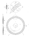
- figs. 1 to 4 (table I) respectively represent overall and detailed views of a cutting disc according to the finding, in a first possible configuration thereof;
- figs. 5 to 8 (table II) respectively represent overall and detailed views of a cutting disc according to the finding, in a second possible configuration thereof;
- figs. 9 to 12 (table III) respectively represent overall and detailed views of a cutting disc according to the finding, in a third possible configuration thereof.
- As can be seen in the figures, a so-called diamond-tipped cutting disc, wholly indicated with
reference numeral 1, consists of a central disc orcore 2 made from steel, equipped with thehole 3 for the attachment to the machine tool and the diamond band orring 4, welded on the outside. - The
ring 4, made from a known abrasive material, is characterised in that itsside surface 5 is equipped withshaped ridges 6 that, when in work, help the cutting operation, constituting in themselves the abrasive surface of the disc. - As can be seen in figs. 1 to 4 in a first possible embodiment the shaped ridges, wholly indicated with
reference numeral 6 and projecting from thewall 5, comprise plates 8.1, with circular profile, contained inside theborder rings 7. - Alternatively, as can be seen in figures 5 to 8, in a second possible embodiment the shaped ridges, wholly indicated with
reference numeral 6 and projecting from thewall 5, compriserings 7, arranged circumferentially and concentrically on thewall 5, which intersect the plates 8.2, with a substantially quadrilateral profile. - Substantially, as can be seen in figs. 9 to 12, with the superposition of the two possible embodiments, a third embodiment is obtained in which, thanks to the mutual interference between the
rings 7 and the plates 8.1 and 8.2, anabrasive surface 5 is obtained equipped withshaped ridges 6, which allow a substantially advantageous cutting action such as to completely satisfy all of the processing requirements required for cutting and chamfering all types of stone and ceramic materials. - Of course, further embodiments of the diamond ring are possible, in which the
side walls 5 have projections configured even in a substantially different way to those illustrated and described, without for this reason departing from the scope of the claims, defined hereafter.
Claims (9)
- DIAMOND-TIPPED CUTTING DISC, to be used for cutting or chamfering different products, from natural stones to ceramics, from granite and marble floor tiles to single fired products and from fine compact clinker bricks to hard porcelain stoneware, said disc consisting of a central disc or core (2) made from steel, equipped with the hole (3) for the attachment to the machine tool and a diamond band or ring (4), arranged on the outside with respect to the first,
characterised in that
the diamond band (4) has shaped ridges (6) on a side wall (5) or on both of the side walls, said ridges constituting the abrasive surface of the tool. - DIAMOND-TIPPED CUTTING DISC, according to claim 1, characterised in that the ridges consist of surface portions that are arranged, with modular progression, circumferentially.
- DIAMOND-TIPPED CUTTING DISC, according to claim 2, characterised in that the ridges occupy the entire wall of the diamond band.
- DIAMOND-TIPPED CUTTING DISC, according to claim 3, characterised in that the ridges (6) are obtained through recesses that define two types of configurations: circumferential rings (7), arranged concentrically on the side wall of the diamond band and a plurality of plates (8), arranged substantially transversally with respect to the circumference of the aforementioned rings.
- DIAMOND-TIPPED CUTTING DISC, according to claim 4, characterised in that the ridges (6) have straight sides.
- DIAMOND-TIPPED CUTTING DISC, according to claim 4, characterised in that the ridges (6) have inclined sides, so as to make sections diverging towards the outside.
- DIAMOND-TIPPED CUTTING DISC, according to claim 4, characterised in that the plates (8) have a circular profile (8.1).
- DIAMOND-TIPPED CUTTING DISC, according to claim 4, characterised in that the plates (8) have a polyhedral profile, preferably quadrilateral (8.2).
- DIAMOND-TIPPED CUTTING DISC, according to one or more of the previous claims, characterised in that the diamond band (4) has the surface (5) equipped with ridges (6) resulting from the mutual intersection between the circumferential rings (7) and of the radial plates (8.1, 8.2).
Applications Claiming Priority (2)
| Application Number | Priority Date | Filing Date | Title |
|---|---|---|---|
| IT000018A ITVI20040018A1 (en) | 2004-02-09 | 2004-02-09 | DIAMOND CUTTING DISC |
| ITVI20040018 | 2004-02-09 |
Publications (2)
| Publication Number | Publication Date |
|---|---|
| EP1561534A1 true EP1561534A1 (en) | 2005-08-10 |
| EP1561534B1 EP1561534B1 (en) | 2007-07-25 |
Family
ID=34674597
Family Applications (1)
| Application Number | Title | Priority Date | Filing Date |
|---|---|---|---|
| EP05002335A Expired - Lifetime EP1561534B1 (en) | 2004-02-09 | 2005-02-04 | Diamond-tipped cutting disc |
Country Status (4)
| Country | Link |
|---|---|
| EP (1) | EP1561534B1 (en) |
| AT (1) | ATE367879T1 (en) |
| DE (1) | DE602005001707D1 (en) |
| IT (1) | ITVI20040018A1 (en) |
Cited By (2)
| Publication number | Priority date | Publication date | Assignee | Title |
|---|---|---|---|---|
| RU2308118C1 (en) * | 2006-04-07 | 2007-10-10 | Федеральное государственное унитарное предприятие "Научно-производственное предприятие "Исток" (ФГУП НПП "Исток") | Diamond-containing disk for machining materials for electronic-engineering and parts made of them |
| EP2954966A1 (en) * | 2014-06-13 | 2015-12-16 | Meccanotecnica Veneta S.r.L. | Cutter disc, cutting device and method for obtaining such a cutter disc |
Citations (4)
| Publication number | Priority date | Publication date | Assignee | Title |
|---|---|---|---|---|
| DE3513687A1 (en) * | 1985-04-16 | 1986-10-30 | Claudio 8962 Pfronten Mussner | Diamond cut-off wheel |
| CH664524A5 (en) * | 1983-05-25 | 1988-03-15 | Jiro Inoue | Saw bit in sintered metal |
| JPH0760650A (en) * | 1993-08-25 | 1995-03-07 | Tone Corp | Silent, strong diamond blade substrate |
| EP0836903A1 (en) * | 1996-10-16 | 1998-04-22 | Said Spa | diamond disc tool for cutting granite, marble, reinforced concrete and stony materials in general |
-
2004
- 2004-02-09 IT IT000018A patent/ITVI20040018A1/en unknown
-
2005
- 2005-02-04 AT AT05002335T patent/ATE367879T1/en not_active IP Right Cessation
- 2005-02-04 DE DE602005001707T patent/DE602005001707D1/en not_active Expired - Lifetime
- 2005-02-04 EP EP05002335A patent/EP1561534B1/en not_active Expired - Lifetime
Patent Citations (4)
| Publication number | Priority date | Publication date | Assignee | Title |
|---|---|---|---|---|
| CH664524A5 (en) * | 1983-05-25 | 1988-03-15 | Jiro Inoue | Saw bit in sintered metal |
| DE3513687A1 (en) * | 1985-04-16 | 1986-10-30 | Claudio 8962 Pfronten Mussner | Diamond cut-off wheel |
| JPH0760650A (en) * | 1993-08-25 | 1995-03-07 | Tone Corp | Silent, strong diamond blade substrate |
| EP0836903A1 (en) * | 1996-10-16 | 1998-04-22 | Said Spa | diamond disc tool for cutting granite, marble, reinforced concrete and stony materials in general |
Non-Patent Citations (1)
| Title |
|---|
| PATENT ABSTRACTS OF JAPAN vol. 1995, no. 06 31 July 1995 (1995-07-31) * |
Cited By (2)
| Publication number | Priority date | Publication date | Assignee | Title |
|---|---|---|---|---|
| RU2308118C1 (en) * | 2006-04-07 | 2007-10-10 | Федеральное государственное унитарное предприятие "Научно-производственное предприятие "Исток" (ФГУП НПП "Исток") | Diamond-containing disk for machining materials for electronic-engineering and parts made of them |
| EP2954966A1 (en) * | 2014-06-13 | 2015-12-16 | Meccanotecnica Veneta S.r.L. | Cutter disc, cutting device and method for obtaining such a cutter disc |
Also Published As
| Publication number | Publication date |
|---|---|
| DE602005001707D1 (en) | 2007-09-06 |
| EP1561534B1 (en) | 2007-07-25 |
| ATE367879T1 (en) | 2007-08-15 |
| ITVI20040018A1 (en) | 2004-05-09 |
Similar Documents
| Publication | Publication Date | Title |
|---|---|---|
| US20220055183A1 (en) | Machining segment for a machining tool | |
| KR100285413B1 (en) | Rim type diamond blade | |
| KR20030027434A (en) | Diamond tool | |
| KR100923567B1 (en) | Cutting saw blades for circular saws for metal cutting | |
| DE69924993D1 (en) | MODULAR CIRCULAR SAW BLADDER SYSTEM FOR FORMING CURVED SURFACES IN MARBLE, STONE OR SIMILAR MATERIALS | |
| EP1561534B1 (en) | Diamond-tipped cutting disc | |
| WO2007022016A3 (en) | Abrasive tool | |
| EP3013518B1 (en) | Cutting blade with regenerating edge segments | |
| US2815746A (en) | Cut-off blades for abrasive bodies and their production | |
| KR100680850B1 (en) | Cutting Tips and Diamond Tools for Diamond Tools | |
| ITMI960692U1 (en) | DIAMOND DISC-TYPE TOOL PARTICULARLY DESIGNED FOR CUTTING GRANITE, MARBLE, REINFORCED CEMENT AND MATERIALS | |
| ATE283145T1 (en) | MACHINE FOR PROCESSING ROCK SURFACES, ESPECIALLY STONE SLABS OR THE LIKE, AS WELL AS MARBLE, GRANITE, BUT ALSO CERAMICS AND OTHER BUILDING MATERIALS, USED FOR FLOORS AND COVERINGS | |
| TWM505373U (en) | Grinding wheel with chip drain | |
| KR100680851B1 (en) | Horizontal Reciprocating Cutting Tips and Cutting Tools | |
| KR100910592B1 (en) | Machining tips and machining tools equipped with them | |
| CN207432038U (en) | A kind of processing of stone diamond bora structure | |
| KR100764911B1 (en) | Cutting tools | |
| CN205219453U (en) | Combined diamond saw blade | |
| WO2006000542A1 (en) | Lapping head for machining workpieces of hard stone materials | |
| KR100583464B1 (en) | Diamond tools | |
| CA2603270C (en) | Cut-off wheel | |
| EP4506102A1 (en) | Segments with oriented diamond particles and tool insert equipped with the segments | |
| CN113290509A (en) | Novel high-hardness diamond grinding wheel | |
| JP2006205330A (en) | Grinding wheel | |
| CN210232714U (en) | Block-shaped tooth-shaped grinding wheel |
Legal Events
| Date | Code | Title | Description |
|---|---|---|---|
| PUAI | Public reference made under article 153(3) epc to a published international application that has entered the european phase |
Free format text: ORIGINAL CODE: 0009012 |
|
| AK | Designated contracting states |
Kind code of ref document: A1 Designated state(s): AT BE BG CH CY CZ DE DK EE ES FI FR GB GR HU IE IS IT LI LT LU MC NL PL PT RO SE SI SK TR |
|
| AX | Request for extension of the european patent |
Extension state: AL BA HR LV MK YU |
|
| 17P | Request for examination filed |
Effective date: 20051205 |
|
| AKX | Designation fees paid |
Designated state(s): AT BE BG CH CY CZ DE DK EE ES FI FR GB GR HU IE IS IT LI LT LU MC NL PL PT RO SE SI SK TR |
|
| GRAP | Despatch of communication of intention to grant a patent |
Free format text: ORIGINAL CODE: EPIDOSNIGR1 |
|
| RIN1 | Information on inventor provided before grant (corrected) |
Inventor name: GARBIN, RUGGERO |
|
| GRAS | Grant fee paid |
Free format text: ORIGINAL CODE: EPIDOSNIGR3 |
|
| GRAA | (expected) grant |
Free format text: ORIGINAL CODE: 0009210 |
|
| AK | Designated contracting states |
Kind code of ref document: B1 Designated state(s): AT BE BG CH CY CZ DE DK EE ES FI FR GB GR HU IE IS IT LI LT LU MC NL PL PT RO SE SI SK TR |
|
| REG | Reference to a national code |
Ref country code: GB Ref legal event code: FG4D |
|
| REG | Reference to a national code |
Ref country code: CH Ref legal event code: EP |
|
| REG | Reference to a national code |
Ref country code: IE Ref legal event code: FG4D |
|
| REF | Corresponds to: |
Ref document number: 602005001707 Country of ref document: DE Date of ref document: 20070906 Kind code of ref document: P |
|
| PG25 | Lapsed in a contracting state [announced via postgrant information from national office to epo] |
Ref country code: PT Free format text: LAPSE BECAUSE OF FAILURE TO SUBMIT A TRANSLATION OF THE DESCRIPTION OR TO PAY THE FEE WITHIN THE PRESCRIBED TIME-LIMIT Effective date: 20071226 Ref country code: NL Free format text: LAPSE BECAUSE OF FAILURE TO SUBMIT A TRANSLATION OF THE DESCRIPTION OR TO PAY THE FEE WITHIN THE PRESCRIBED TIME-LIMIT Effective date: 20070725 Ref country code: ES Free format text: LAPSE BECAUSE OF FAILURE TO SUBMIT A TRANSLATION OF THE DESCRIPTION OR TO PAY THE FEE WITHIN THE PRESCRIBED TIME-LIMIT Effective date: 20071105 Ref country code: LT Free format text: LAPSE BECAUSE OF FAILURE TO SUBMIT A TRANSLATION OF THE DESCRIPTION OR TO PAY THE FEE WITHIN THE PRESCRIBED TIME-LIMIT Effective date: 20070725 Ref country code: BG Free format text: LAPSE BECAUSE OF FAILURE TO SUBMIT A TRANSLATION OF THE DESCRIPTION OR TO PAY THE FEE WITHIN THE PRESCRIBED TIME-LIMIT Effective date: 20071025 Ref country code: FI Free format text: LAPSE BECAUSE OF FAILURE TO SUBMIT A TRANSLATION OF THE DESCRIPTION OR TO PAY THE FEE WITHIN THE PRESCRIBED TIME-LIMIT Effective date: 20070725 Ref country code: IS Free format text: LAPSE BECAUSE OF FAILURE TO SUBMIT A TRANSLATION OF THE DESCRIPTION OR TO PAY THE FEE WITHIN THE PRESCRIBED TIME-LIMIT Effective date: 20071125 |
|
| REG | Reference to a national code |
Ref country code: CH Ref legal event code: PL |
|
| NLV1 | Nl: lapsed or annulled due to failure to fulfill the requirements of art. 29p and 29m of the patents act | ||
| PG25 | Lapsed in a contracting state [announced via postgrant information from national office to epo] |
Ref country code: CH Free format text: LAPSE BECAUSE OF FAILURE TO SUBMIT A TRANSLATION OF THE DESCRIPTION OR TO PAY THE FEE WITHIN THE PRESCRIBED TIME-LIMIT Effective date: 20070725 Ref country code: PL Free format text: LAPSE BECAUSE OF FAILURE TO SUBMIT A TRANSLATION OF THE DESCRIPTION OR TO PAY THE FEE WITHIN THE PRESCRIBED TIME-LIMIT Effective date: 20070725 Ref country code: LI Free format text: LAPSE BECAUSE OF FAILURE TO SUBMIT A TRANSLATION OF THE DESCRIPTION OR TO PAY THE FEE WITHIN THE PRESCRIBED TIME-LIMIT Effective date: 20070725 Ref country code: AT Free format text: LAPSE BECAUSE OF FAILURE TO SUBMIT A TRANSLATION OF THE DESCRIPTION OR TO PAY THE FEE WITHIN THE PRESCRIBED TIME-LIMIT Effective date: 20070725 |
|
| EN | Fr: translation not filed | ||
| PG25 | Lapsed in a contracting state [announced via postgrant information from national office to epo] |
Ref country code: BE Free format text: LAPSE BECAUSE OF FAILURE TO SUBMIT A TRANSLATION OF THE DESCRIPTION OR TO PAY THE FEE WITHIN THE PRESCRIBED TIME-LIMIT Effective date: 20070725 |
|
| PG25 | Lapsed in a contracting state [announced via postgrant information from national office to epo] |
Ref country code: GR Free format text: LAPSE BECAUSE OF FAILURE TO SUBMIT A TRANSLATION OF THE DESCRIPTION OR TO PAY THE FEE WITHIN THE PRESCRIBED TIME-LIMIT Effective date: 20071026 Ref country code: DK Free format text: LAPSE BECAUSE OF FAILURE TO SUBMIT A TRANSLATION OF THE DESCRIPTION OR TO PAY THE FEE WITHIN THE PRESCRIBED TIME-LIMIT Effective date: 20070725 |
|
| PG25 | Lapsed in a contracting state [announced via postgrant information from national office to epo] |
Ref country code: SK Free format text: LAPSE BECAUSE OF FAILURE TO SUBMIT A TRANSLATION OF THE DESCRIPTION OR TO PAY THE FEE WITHIN THE PRESCRIBED TIME-LIMIT Effective date: 20070725 Ref country code: CZ Free format text: LAPSE BECAUSE OF FAILURE TO SUBMIT A TRANSLATION OF THE DESCRIPTION OR TO PAY THE FEE WITHIN THE PRESCRIBED TIME-LIMIT Effective date: 20070725 |
|
| PLBE | No opposition filed within time limit |
Free format text: ORIGINAL CODE: 0009261 |
|
| STAA | Information on the status of an ep patent application or granted ep patent |
Free format text: STATUS: NO OPPOSITION FILED WITHIN TIME LIMIT |
|
| PG25 | Lapsed in a contracting state [announced via postgrant information from national office to epo] |
Ref country code: RO Free format text: LAPSE BECAUSE OF FAILURE TO SUBMIT A TRANSLATION OF THE DESCRIPTION OR TO PAY THE FEE WITHIN THE PRESCRIBED TIME-LIMIT Effective date: 20070725 Ref country code: SE Free format text: LAPSE BECAUSE OF FAILURE TO SUBMIT A TRANSLATION OF THE DESCRIPTION OR TO PAY THE FEE WITHIN THE PRESCRIBED TIME-LIMIT Effective date: 20071025 |
|
| 26N | No opposition filed |
Effective date: 20080428 |
|
| PG25 | Lapsed in a contracting state [announced via postgrant information from national office to epo] |
Ref country code: DE Free format text: LAPSE BECAUSE OF FAILURE TO SUBMIT A TRANSLATION OF THE DESCRIPTION OR TO PAY THE FEE WITHIN THE PRESCRIBED TIME-LIMIT Effective date: 20071026 Ref country code: FR Free format text: LAPSE BECAUSE OF FAILURE TO SUBMIT A TRANSLATION OF THE DESCRIPTION OR TO PAY THE FEE WITHIN THE PRESCRIBED TIME-LIMIT Effective date: 20080321 |
|
| PG25 | Lapsed in a contracting state [announced via postgrant information from national office to epo] |
Ref country code: MC Free format text: LAPSE BECAUSE OF NON-PAYMENT OF DUE FEES Effective date: 20080228 |
|
| PG25 | Lapsed in a contracting state [announced via postgrant information from national office to epo] |
Ref country code: EE Free format text: LAPSE BECAUSE OF FAILURE TO SUBMIT A TRANSLATION OF THE DESCRIPTION OR TO PAY THE FEE WITHIN THE PRESCRIBED TIME-LIMIT Effective date: 20070725 Ref country code: IE Free format text: LAPSE BECAUSE OF NON-PAYMENT OF DUE FEES Effective date: 20080204 |
|
| PG25 | Lapsed in a contracting state [announced via postgrant information from national office to epo] |
Ref country code: SI Free format text: LAPSE BECAUSE OF FAILURE TO SUBMIT A TRANSLATION OF THE DESCRIPTION OR TO PAY THE FEE WITHIN THE PRESCRIBED TIME-LIMIT Effective date: 20070725 |
|
| PG25 | Lapsed in a contracting state [announced via postgrant information from national office to epo] |
Ref country code: CY Free format text: LAPSE BECAUSE OF FAILURE TO SUBMIT A TRANSLATION OF THE DESCRIPTION OR TO PAY THE FEE WITHIN THE PRESCRIBED TIME-LIMIT Effective date: 20070725 |
|
| GBPC | Gb: european patent ceased through non-payment of renewal fee |
Effective date: 20090204 |
|
| PG25 | Lapsed in a contracting state [announced via postgrant information from national office to epo] |
Ref country code: GB Free format text: LAPSE BECAUSE OF NON-PAYMENT OF DUE FEES Effective date: 20090204 |
|
| PG25 | Lapsed in a contracting state [announced via postgrant information from national office to epo] |
Ref country code: HU Free format text: LAPSE BECAUSE OF FAILURE TO SUBMIT A TRANSLATION OF THE DESCRIPTION OR TO PAY THE FEE WITHIN THE PRESCRIBED TIME-LIMIT Effective date: 20080126 Ref country code: LU Free format text: LAPSE BECAUSE OF NON-PAYMENT OF DUE FEES Effective date: 20080204 |
|
| PG25 | Lapsed in a contracting state [announced via postgrant information from national office to epo] |
Ref country code: TR Free format text: LAPSE BECAUSE OF FAILURE TO SUBMIT A TRANSLATION OF THE DESCRIPTION OR TO PAY THE FEE WITHIN THE PRESCRIBED TIME-LIMIT Effective date: 20070725 |
|
| PGFP | Annual fee paid to national office [announced via postgrant information from national office to epo] |
Ref country code: IT Payment date: 20080228 Year of fee payment: 4 |