EP1561434A1 - Denture attachment, denture and process for producing the same - Google Patents
Denture attachment, denture and process for producing the same Download PDFInfo
- Publication number
- EP1561434A1 EP1561434A1 EP04772800A EP04772800A EP1561434A1 EP 1561434 A1 EP1561434 A1 EP 1561434A1 EP 04772800 A EP04772800 A EP 04772800A EP 04772800 A EP04772800 A EP 04772800A EP 1561434 A1 EP1561434 A1 EP 1561434A1
- Authority
- EP
- European Patent Office
- Prior art keywords
- attachment
- dental
- cap
- denture
- keeper
- Prior art date
- Legal status (The legal status is an assumption and is not a legal conclusion. Google has not performed a legal analysis and makes no representation as to the accuracy of the status listed.)
- Granted
Links
Images





Classifications
-
- A—HUMAN NECESSITIES
- A61—MEDICAL OR VETERINARY SCIENCE; HYGIENE
- A61C—DENTISTRY; APPARATUS OR METHODS FOR ORAL OR DENTAL HYGIENE
- A61C13/00—Dental prostheses; Making same
- A61C13/225—Fastening prostheses in the mouth
- A61C13/235—Magnetic fastening
Definitions
- This invention relates to a dental attachment which is used to embed a denture by magnetic force, and a denture which is comprised using such a dental attachment, and a method of manufacturing thereof.
- a dental attachment 91 which has a magnetic body, is, as is shown in FIG10, embedded in the denture base 810, which is fixed with artificial tooth 81.
- a keeper 92 made of soft magnetic material is embedded in the root cap 82 or an implant (the embodiment is abbreviated) is embedded. Therefore the denture, which has dental attachment 91, can be fixed to the keeper 92 by magnetic attractive force.
- the denture is put in a oral space for about two weeks without a dental attachment (magnetic assembly) built in the denture and when the submergence of the gingiva is stabilized, a dentist has combined a dental attachment to said denture. So the stress to the abutment where the dental attachment works is alleviated. But in about half a year, the gingiva gradually submerges and modification of the denture and recombination of the dental attachment are needed.
- dentists desire that the dental attachment should be combined with a denture in the making process before dentists work to put the dental attachment into a denture.
- the combination is done, where and how much gingiva submerges cannot be predicted. Therefore, if a denture, which is combined with a dental attachment in a conventional making process, is put on for about a week, the stress to an abutment is concentrated and a strange feeling or ache is generated.
- Patent reference 1 Japanese published unexamined patent application 7-136190 patent reference 2; Japanese unexamined utility model application 6- 86715
- the present invention provides a dental attachment which can restrain the concentration of occluding stress to the part where the dental attachment is combined even after long use, a denture using that dental attachment, and its manufacturing method.
- a first aspect of the invention is a dental attachment which is embedded in the dental base in order to be combined with said attachment with the keeper made of soft magnetic material in the tooth root by magnetic attractive force.
- Said dental attachment comprises an attachment body which has a magnetic body exercising magnetic attractive force and in said attachment body, a cap covering the head portion which is placed on the side opposite to the absorbing face which is combined with said keeper.
- Said cap is made of non-magnetic material and is made to be able to move a set distance between the connecting position to the said head portion and the set extended position.
- the dental attachment of the present invention has, as said, a cap which is movable between said connecting position and the extended position. Therefore the whole denture containing a cap can move to the said attachment body embedded with fixed said cap. So, even if the place where a keeper and attachment body is connected is fixed, the whole denture with said cap can be moved relative to said keeper within said set distance. Therefore even if the denture is made on a model, the denture with said dental attachment can be moved according to the change of the shape of the abutment. Therefore, the denture with said dental attachment can restrain the concentration of the occluding stress even if it is completed on the model in the making process.
- the attachment body (sometimes called a magnet assembly) may have any well-known structure.
- the keeper which is combined to a dental attachment, may have any well-known structure.
- the absorbing face on said dental attachment may be flat, may have a convex face, or may have a concave face with a set curvature.
- the second invention is a denture which consists of a artificial tooth planted in the dental base and the dental attachment embedded in said dental base to contact the keeper made of soft magnetic material built in the root part by magnetic attractive force.
- Said dental attachment consists of an attachment body, which has a magnetic body exercising magnetic attractive force, and the cap of the attachment body covering the head portion, which is placed on the opposite side of the contacting face to said keeper.
- Said cap is made of non-magnetic material and is connected in said attachment body to be able to move in the set distance between the connecting place to said head portion part and the extended place.
- the denture has a feature that said cap is held in said dental base and that said attachment body is embedded so as to be movable to said cap. (claim6)
- the invented denture has the so constituted dental attachment.
- a dental base holds the cap and said attachment body is embedded so as to be able to be movable to the cap. Therefore, if at the beginning of use, said attachment body is moved forward and set so as to make a gap between head portion and the cap, the cap moves forward relative to the attachment body after use and the placement position of the denture can be changed.
- this invented denture can restrain the concentration of occluding stress at the combining part at the opposite side of the absorbing face to join said keeper of dental attachment.
- a third aspect of the invention is the method of manufacturing the denture in which the artificial tooth is planted in the dental base and the dental attachment is embedded in said dental base so as to be joined to the keeper made of non-magnetic material in the tooth root part.
- Said dental attachment consists of an attachment body with a magnetic body delivering magnetic attractive force and a cap covering the head portion of said attachment body at the opposite side of the absorbing face to join said keeper.
- Said cap consisting of non-magnetic material is combined to said attachment body so as to be able to move in the set distance between the connecting point to be connected said head portion part and extended point.
- the dental attachment embedded in dental base has a structure with a gap of the thickness of said spacer between the keeper and attachment body. Therefore, when the denture is put on the dental base of the same shape as the model at said keeper and started to be used, facing the keeper, the attachment body moves forward relative to the keeper and is magnetically connected with the keeper. Thus, a gap of the thickness of said spacer exists between the face of the head portion of the attachment body and the cap. After that, as is mentioned, the cap moves forward relative to the attachment body using said gap, according to the change of the shape of the dental base. So, the placement location of the denture changes and the concentration of occluding stress can be restrained.
- Said attachment body of the dental attachment of the said first aspect of the invention consists of said magnetic body, yoke made of soft magnetic material which has a recess housing said magnetic body, a disk made of non-magnetic material which is set so as to close the opening of said recess with said magnetic body housed in said recess, and a ring shaped connecting location made of non-magnetic material to connect said disk and said yoke. It is preferable that said cap covers said head portion which is located on the opposite side of the said yoke with said opening part. (claim 2) In this case, said yoke, disk and the ring shaped connecting part between these can form an ideal magnetic circuit and the magnetic force of said magnetic body can be utilized efficiently.
- the non-magnetic material constituting said yoke can be various soft magnetic materials, for instance, 17Cr stainless steel, 17Cr-2Mo stainless steel, and 19Cr-2Mo stainless steel are preferable. These are superior in non-corrosion and can improve the endurance. Also, as soft magnetic material for said disk, various soft magnetic materials are available and the same materials as the said yoke can be used. Still, the connection of said disk and said yoke is practiced on the ring shaped connecting part made of said non-magnetic material. As a specific connecting method, welding is applicable. Also, as said magnetic body built in said yoke, a magnet with high magneto motive force per unit volume is used. Specifically, for instance, Sm-Co based, Nd-Fe-B based, or rare earth magnets with high-energy product are preferable.
- said attachment body has collars protruding axially outward from the outer peripheral surface thereof.
- Said cap has a bottom part to face said portion part and a lateral part which faces said outer peripheral surface and covers said collars.
- said lateral part has a part protruding inward to said outer peripheral surface of said attachment body and it is preferable that said cap is constituted so as to fit said part protruding inward with said collars. (Claim3)
- the outer peripheral surface of said cap has a taper that has a smaller diameter as it becomes further away from said bottom and/or a part protruding outward (Claim4) .
- said taper face or outer protruding part bites and exerts the undercut effect, so the fitting strength of both can be improved.
- said cap is made of synthetic resin (claim 5).
- synthetic resin for instance, POM, PE, PET etc. can be used.
- said spacer is preferably made of permanent magnetic or soft magnetic material (claim8) .
- said spacer when a spacer is equipped on said keeper, the location between both can be maintained stably, and also when the dental attachment is equipped on the spacer, the location between both can be maintained stably. Therefore, afterward the uniting process of the dental attachment can be stably done.
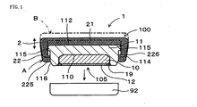
- FIG 1 A first embodiment of the dental attachment of the present invention is explained using FIG 1.
- the dental attachment 1 of this example is, as is shown in FIG 1, a dental attachment which is embedded in the dental base so as to be conjugated to the keeper 92 made of soft magnetic material in the tooth root by magnetic attractive force.
- the dental attachment 1 consists attachment body 100 which has magnetic body 10 exerting magnetic attractive force and cap2 covering head portion 112 which is located at the side opposite to the absorbing face 105 to fit keeper 92 of said attachment body 100.
- Cap2 made of non-magnetic material, is fit to said attachment body 100 so as to be able to move between connecting location (A) with said head portion 112 and the extended location(B) which is a certain amount away.
- Said attachment 100 consists, as is shown in the same FIG, of magnetic body 10 exerting magnetic attractive force, yoke 110 made of soft magnetic material which has recess 110 housing said magnetic body, disk 12 which covers the opening part of said recess110 with said magnetic body 10 housed in said recess, and ring shaped connecting part 19, made of non-magnetic material, which connects said disk12 with said yoke 11.
- Cap 2 covers said head portion 112 which is opposite side to said opening part of said yoke 11. Below this is explained in more detail.
- yoke 11 of the present dental attachment is almost disk shaped and has collars 115 protruding axially outward from the outer peripheral surface 114.
- collars 115 is made all over the outer peripheral surface 114 at the edge of said head portion 112.
- collars 115 can be made, for instance, at axially plural separated locations.
- said yoke 11 is made of soft magnetic material, 19Cr-2Mo-O.2Ti-Fe, and made by machining.
- Yoke11 has recess 110 to house magnetic 10 by machining.
- the inner diameter of this recess 110 is corresponding to the outer diameter of magnetic body 10 described later.
- the corner of the outer periphery of the face, which has a recess 110, has taper shaped chamfer 118.
- Said disk 12 is made of soft magnetic material, 19Cr-2Mo-O.2Ti-Fe. After said magnetic body 10 is inserted in the recess of said yoke 11, said disk is inserted and the outer peripheral thereof is welded to yoke11 with the ring shaped connecting part 19 made of non-magnetic material.
- Cap 2 has bottom 21 which faces head portion 112 of yoke 11 and lateral part 22 which faces said outer peripheral surface 114 and covers said collars 115.
- the lateral part 22 has inward protruding part 225 which protrudes toward outer peripheral surface114 of yoke 11 and is structured to fit the inward protruding part with collars 115 when cap 2 is located at the extended location (B) .
- cap 2 has, as is shown in the same FIG, taper face 226 which has a smaller diameter as it is further away from said bottom 21 at the outer peripheral face of lateral part 22.
- the present dental attachment 1 has cap 2, which is movable between connecting part (A) and extended part (B), and is structured to be changeable to the relative position between said cap 2 and yoke11. Because of this structure, the denture with said cap 2 fixed in the dental base can change the relative position of the whole denture to yoke 11 (attachment body100), and excellent operating effects can be exerted.
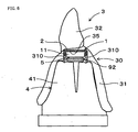
- the present denture 3 consists, as is shown in FIG2, of artificial tooth 32 planted in dental base 31 and dental attachment 1 of embodiment 1 in said dental base.
- Cap 2 is held in said dental base 31 and yoke 11 (attachment body 100) can be movable to cap 2.
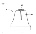
- the first step to manufacture this denture is as is shown in FIG3; said artificial tooth 32 is planted in dental base 31 and denture body 30 which has recess 35 to insert dental attachment 1 in dental base 31 is manufactured. Also, as is shown in FIG4, model 4 on the keeper side which is embedded keeper 92 in the model gingiva 41 which copies the gingival shape including a tooth root part to install denture3 is manufactured.
- the manufacturing process of this model on the keeper side can be done before or after the manufacturing process of said denture body and both process can be done in parallel.
- adhesive 310 is applied inside said recess 35 of said denture body 30 and denture body 30 covers model 4 on the keeper side in order to house dental attachment 1 in recess 35.
- cap 2 of dental attachment 1 is fixed in recess 35 with adhesive 310, completing denture 3 which has dental attachment 1.
- cap 2 of the installed dental attachment is fixed and yoke 11 (attachment body 100) is held to be movable to said cap.
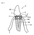
- the starting point of yoke 11 is set between the connecting point of yoke 11 with cap 2 and the connecting point with keeper 92 at the advanced point of the thickness of said spacer 5. Therefore, as is shown in FIG 7, when keeper 92 is embedded in real gingiva 88, which is an original of model 4 on said keeper side, and denture 3 is put on it, as is shown in the same FIG, yoke 11 advances relative to cap2 and contacts keeper 92 and is connected. Therefore, at the starting step of usage, a certain amount of gap C between cap 2 and yoke 11 is made and it become a space which adapts to the subsequent change over time.
- dental attachment 1 of the present example can move relatively so as to shrink room C between yoke 11 and cap 2. Therefore, denture 3 can follow the change of gingiva 88's submerging and move to a suitable position. Therefore, in the present denture 3, even in the case that gingiva 88 etc. is changed by time, the concentration of the occluding stress on the combining part of the dental attachment can be restrained.
- a denture with a plurality of artificial teeth is especially effective, but a denture with only one artificial tooth 32 can also be excellently effective to exert the operating effect of said dental attachment 1.
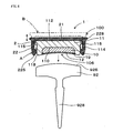
- absorbing surface 106 is made of a concave surface (spherical face) .
- absorbed surface 926 which is made of a convex surface (spherical face) and can be fit to said absorbing surface 106 is adopted.
- Said keeper 92 has a post 928 which is extended from the back center on the opposite side of absorbing surface 926.
- Cap 2 which covers head portion 112 of attachment body 100 has cap collars 228 protruding outward at all outer peripheral surfaces of lateral part 22.
- the structure is the same as embodiment 1.
- the present example of the dental attachment which has concave absorbing surface 106 as mentioned above, can be used in combination with keeper 92 which has convex absorbed surface 926. Therefore, the fitting condition of absorbing surface 106 and absorbed surface 926 is maintained and can be inclined from the starting condition. For some kinds of dentures, adopting this structure is very effective.
- said cap 2 has cap collars 228.
- cap collars 228 When cap 2 is connected to dental base 31 with adhesive 310, cap collars 228 is embedded in adhesive 310 and the connecting strength between cap 2 and dental base 31 can be improved. Still, said cap collars 228 need not be made all around and a shape with at least one radially protruding part is possible. It also obtains the same operating effect as embodiment 1.
- the manufacturing method of the denture is explained by using the dental attachment of embodiment 3.
- the manufacturing method of the present example which is basically the same as embodiment 2, is changed in the shape and materials of spacer 52. That is, first, like embodiment 2, the manufacturing process of denture body 30 and the manufacturing process of model 4, which has keeper 92 in model gingiva 41 on the keeper side, is performed.
- the setting process of the dental attachment is performed by using disk shaped spacer 52 which is made of soft magnetic material, 19Cr-2Mo-O, and has the thickness of about the same as the moving distance of cap 2 of said dental attachment 1 and has a spherical shape with the same curvature as the absorbing surface 106 of said attachment body 100 and absorbed surface 926 of keeper 92. Said spacer 52 and absorbed surface 926 are connected with adhesive. The process afterward is the same as embodiment 2.
- the dental attachment which has concave absorbing surface 106, can be easily installed in denture body 30 by using a disk shaped spacer of said spherical shape. It also obtains the same operating effect as embodiment 2.
Landscapes
- Health & Medical Sciences (AREA)
- Oral & Maxillofacial Surgery (AREA)
- Dentistry (AREA)
- Epidemiology (AREA)
- Life Sciences & Earth Sciences (AREA)
- Animal Behavior & Ethology (AREA)
- General Health & Medical Sciences (AREA)
- Public Health (AREA)
- Veterinary Medicine (AREA)
- Dental Prosthetics (AREA)
Abstract
Description
A
Also, the development of the manufacturing method of a denture with a dental attachment has been desired.
Said dental attachment comprises an attachment body which has a magnetic body exercising magnetic attractive force and in said attachment body, a cap covering the head portion which is placed on the side opposite to the absorbing face which is combined with said keeper.
Said cap is made of non-magnetic material and is made to be able to move a set distance between the connecting position to the said head portion and the set extended position. ( claim 1)
Therefore, the denture with said dental attachment can restrain the concentration of the occluding stress even if it is completed on the model in the making process.
Yet also it is needless to say that even in the case that without combining the dental attachment to the denture in the making process, the dentist combines the dental attachment to the denture after stabilizing the submergence of the gingiva in the conventional way, and the necessity to modify the denture and recombine the dental attachment can be reduced.
Furthermore, the absorbing face on said dental attachment, as is shown in the following embodiment, may be flat, may have a convex face, or may have a concave face with a set curvature.
Said dental attachment consists of an attachment body, which has a magnetic body exercising magnetic attractive force, and the cap of the attachment body covering the head portion, which is placed on the opposite side of the contacting face to said keeper.
Said cap is made of non-magnetic material and is connected in said attachment body to be able to move in the set distance between the connecting place to said head portion part and the extended place.
Also, the denture has a feature that said cap is held in said dental base and that said attachment body is embedded so as to be movable to said cap. (claim6)
Said dental attachment consists of an attachment body with a magnetic body delivering magnetic attractive force and a cap covering the head portion of said attachment body at the opposite side of the absorbing face to join said keeper. Said cap consisting of non-magnetic material is combined to said attachment body so as to be able to move in the set distance between the connecting point to be connected said head portion part and extended point.
A process of making a model at the keeper side in which said keeper is embedded in the mimic denture base which imitates the shape of the denture base containing said tooth root,
A process of setting a dental attachment in which a spacer, which has a thickness within the movable range of said cap of said dental attachment, is put on said keeper of model at said keeper side and in which the dental attachment is put so as to connect said disk to said spacer and also said cap of said dental attachment is embedded at the said connecting location, and
A process of uniting the dental attachment in which said dental body is covered on said model at the keeper side so as to house said dental attachment in said recess applied with adhesive inside. (claim 7)
In this case, said yoke, disk and the ring shaped connecting part between these can form an ideal magnetic circuit and the magnetic force of said magnetic body can be utilized efficiently.
Also, as soft magnetic material for said disk, various soft magnetic materials are available and the same materials as the said yoke can be used. Still, the connection of said disk and said yoke is practiced on the ring shaped connecting part made of said non-magnetic material. As a specific connecting method, welding is applicable.
Also, as said magnetic body built in said yoke, a magnet with high magneto motive force per unit volume is used. Specifically, for instance, Sm-Co based, Nd-Fe-B based, or rare earth magnets with high-energy product are preferable.
By this structure, relative movement between said cap and said attachment body is possible and the moving distance between said collars and said inward protruding part can be easily controlled by fitting them.
As said synthetic resin, for instance, POM, PE, PET etc. can be used.
The
Below this is explained in more detail.
Yoke11 has
Said
The
Also, as is shown in FIG4,
Specifically, as is shown in the same FIG, first, said
Therefore, as is shown in FIG 7, when
As is shown in FIG 8, first, absorbing
In other respects the structure is the same as
It also obtains the same operating effect as
The manufacturing method of the present example, which is basically the same as
That is, first, like
The process afterward is the same as
It also obtains the same operating effect as
Claims (8)
- A dental attachment, which is embedded in the dental base so as to fix to a keeper made of soft magnet material and embedded in a tooth root, characterized in that:the said attachment is comprised of an attachment body which has a magnetic body delivering a magnetic attractive force and a cap covering a head portion which is located on the side opposite to the absorbing surface to fit said keeper of said attachment body;the said cap made of non-magnetic material and fixed to said attachment body so as to be able to move a certain distance between the contacting position with said head portion and extended position.
- The dental attachment according to claim1, characterized in that the said attachment body is composed of said magnetic body, a yoke made of soft magnetic material with said concave part which has said magnetic body, a disk made of soft magnetic material which is installed so as to close the opening part of said concave part with said magnetic body housed in said concave part, and ring shaped contacting part made of non-magnetic material which connects said disk and said yoke, and said cap is covered on said head portion which is located on the opposite side to said opening part of said yoke.
- The dental attachment according to claim 1 or claim 2, characterized in that the said attachment body has collars protruding axially outward from the outer peripheral surface thereof, and said cap has a bottom which faces the said head portion and lateral part which faces the said outer peripheral surface of said attachment and covers said collars, and said lateral part has a part protruding inward to said outer peripheral surface of said yoke and said protruding part and said collars are fixed when said cap is located at said extended position.
- The dental attachment according to claim 3, characterized in that the outer peripheral surface of the lateral part of said cap has a tapered surface and/or an outward-protruding part.
- The dental attachment according to one of claims 1~4, characterized in that the said cap is made of synthetic resin.
- A denture having a dental attachment embedded in the said dental base to fix a keeper made of soft magnetic material in a tooth root and an artificial tooth planted in the dental base, characterized in that;said dental attachment has an attachment body which has a magnetic body delivering magnetic attractive force and a cap which covers a head portion which is located on the side opposite to the absorbing surface to contact said keeper of said attachment body;said cap, made of non-magnetic material, fixed to said attachment body so as to move a certain distance between the contacting position which contacts with the said head portion and the extended position;said cap held in said dental base and said attachment body installed so as to be able to move to said cap.
- A method of manufacturing a denture which has a dental attachment in said dental base so as to fix a keeper made of soft magnetic material in a tooth root, with an artificial tooth planted in the dental base, characterized in that:said dental attachment comprising an attachment body which has a magnetic body delivering magnetic attractive force and a cap covering a head portion which is located on the side opposite to the absorbing surface to fix said keeper of said attachment body, said cap, made of non-magnetic material, installed in said attachment body so as to be movable a certain distance between a position contacting said head portion and an extended position;the process of manufacturing a denture body, with said artificial tooth planted in said dental base, which has a recess so as to insert said dental attachment in said dental base,the process of manufacturing a model on the keeper side which has said keeper in the model gingiva of the gingival shape including said tooth root,the process of setting a dental attachment, in which a spacer with a thickness of the range within said cap of said dental attachment can move is installed, and in which a dental attachment is installed so that said spacer is contacted to said disk, and also said cap of said dental attachment is installed in said contacting position, andthe process of fixing a dental attachment, in which said denture body is covered on said model on keeper side so as to house said dental attachment in said recess with adhesive applied inside,included in the method of manufacturing denture.
- The method of manufacturing a denture according to claim 7, characterized in that said spacer is made of a permanent magnet or soft magnetic material.
Applications Claiming Priority (3)
| Application Number | Priority Date | Filing Date | Title |
|---|---|---|---|
| JP2003314499 | 2003-09-05 | ||
| JP2003314499 | 2003-09-05 | ||
| PCT/JP2004/012851 WO2005023140A1 (en) | 2003-09-05 | 2004-09-03 | Denture attachment, denture and process for producing the same |
Publications (3)
| Publication Number | Publication Date |
|---|---|
| EP1561434A1 true EP1561434A1 (en) | 2005-08-10 |
| EP1561434A4 EP1561434A4 (en) | 2007-04-18 |
| EP1561434B1 EP1561434B1 (en) | 2009-11-11 |
Family
ID=34269807
Family Applications (1)
| Application Number | Title | Priority Date | Filing Date |
|---|---|---|---|
| EP04772800A Expired - Lifetime EP1561434B1 (en) | 2003-09-05 | 2004-09-03 | Denture attachment, denture and process for producing the same |
Country Status (6)
| Country | Link |
|---|---|
| US (1) | US8257081B2 (en) |
| EP (1) | EP1561434B1 (en) |
| JP (1) | JP3861922B2 (en) |
| CN (1) | CN1791367B (en) |
| DE (1) | DE602004024025D1 (en) |
| WO (1) | WO2005023140A1 (en) |
Cited By (1)
| Publication number | Priority date | Publication date | Assignee | Title |
|---|---|---|---|---|
| EP2561828A4 (en) * | 2010-04-19 | 2015-07-01 | Aichi Steel Corp | FIXING OF DENTAL PROSTHESIS |
Families Citing this family (11)
| Publication number | Priority date | Publication date | Assignee | Title |
|---|---|---|---|---|
| US20070173934A1 (en) * | 2006-01-20 | 2007-07-26 | Sdgi Holdings, Inc. | Devices to protect features on an implant and methods of use |
| US10687921B2 (en) | 2010-07-02 | 2020-06-23 | Valoc Ag | Connection of a prosthesis structure with an implant structure |
| US20120003606A1 (en) * | 2010-07-02 | 2012-01-05 | Elisabeth Fischler | Connection of a prosthesis structure with an implant structure |
| CN102551904A (en) * | 2010-12-09 | 2012-07-11 | 中国科学院金属研究所 | Dental magnetic retainer |
| JP5689855B2 (en) * | 2012-08-01 | 2015-03-25 | 愛知製鋼株式会社 | Implant, keeper used for implant, and implant body |
| WO2014049589A1 (en) * | 2012-09-27 | 2014-04-03 | Skvirsky Igor | System and method for taking dental impressions |
| ES2869325T3 (en) * | 2017-02-24 | 2021-10-25 | Rhein 83 S R L | dental technology kit |
| US10096267B1 (en) | 2018-01-08 | 2018-10-09 | King Saud University | Dental education model |
| KR102025726B1 (en) * | 2018-03-21 | 2019-11-04 | 박은규 | Attachment for denture |
| CN113262064B (en) * | 2021-05-18 | 2022-05-27 | 深圳市金悠然科技有限公司 | Combined denture with hemispherical magnets and preparation method thereof |
| JP7606718B1 (en) | 2024-06-05 | 2024-12-26 | マグネデザイン株式会社 | Magnetic attachments for dentures |
Family Cites Families (22)
| Publication number | Priority date | Publication date | Assignee | Title |
|---|---|---|---|---|
| FR1493464A (en) | 1966-05-03 | 1967-09-01 | Magnetic device for adhering all dental prostheses to the jawbones and comprising a pressure damping system | |
| US4184252A (en) * | 1977-11-18 | 1980-01-22 | Arthur J. Krol | Overdenture and method for securing same |
| US4530663A (en) * | 1984-07-13 | 1985-07-23 | Portnoy Leonard L | Denture magnetic retention unit |
| US4626213A (en) * | 1985-07-03 | 1986-12-02 | James R. Shiner | Dental appliance |
| FR2587895B1 (en) * | 1985-10-01 | 1990-02-16 | Garrel Andre | MAGNETIC RETENTION DEVICE OF A REMOVABLE DENTAL PROSTHESIS |
| FR2603795B1 (en) * | 1986-09-15 | 1988-12-23 | Garrel Andre | MAGNETIC RETENTION DEVICE OF A REMOVABLE DENTAL PROSTHESIS |
| US4957438A (en) * | 1986-11-25 | 1990-09-18 | Ceka N.V. | Dental coupling assembly and method for its use |
| US4993950A (en) * | 1988-06-20 | 1991-02-19 | Mensor Jr Merrill C | Compliant keeper system for fixed removable bridgework and magnetically retained overdentures |
| NL8900622A (en) * | 1989-03-15 | 1990-10-01 | Elephant Edelmetaal Bv | MAGNETIC ELEMENT FOR A DENTAL PROSTHESIS. |
| JP3196249B2 (en) * | 1991-09-12 | 2001-08-06 | 日立金属株式会社 | Permanent magnet assembly for denture stabilization |
| DE9207951U1 (en) * | 1992-06-12 | 1992-12-03 | Dental-Labor Hartmut Stemmann, 2000 Hamburg | Device for positioning a magnet in a dental prosthesis |
| JPH0728773B2 (en) | 1992-09-09 | 1995-04-05 | 常雄 沖 | Lacquered electromagnetic cooking table |
| JPH07136190A (en) | 1993-11-19 | 1995-05-30 | Aichi Steel Works Ltd | Implants fixed to the edentulous jaw |
| US5417570A (en) * | 1994-01-03 | 1995-05-23 | Zest Anchors, Inc. | Dental anchor assembly |
| FR2718948A1 (en) | 1994-04-20 | 1995-10-27 | Segura Claude | Intra-crown magnetic attachment for removable tooth prosthesis |
| JPH09154856A (en) | 1995-12-01 | 1997-06-17 | Hasegawa Takashi | Fixtures and attachments for dentures |
| JP2893106B2 (en) | 1997-02-19 | 1999-05-17 | 愛知製鋼株式会社 | Denture attachment, method of fixing the same, and fixing spacer |
| KR100331589B1 (en) * | 1998-02-05 | 2002-04-06 | 다카하시 아키오 | False tooth attachment and method and spacer for fixing the same |
| US5871357A (en) * | 1998-04-15 | 1999-02-16 | Tseng; Hsien-Jung | Fixing device for a removable denture |
| JP2000308648A (en) | 1999-04-27 | 2000-11-07 | Gc Dental Products:Kk | Magnet structure having low pressure of dental magnetic attachment, magnet structure used therefor, and cover body therefor |
| JP2002102258A (en) * | 2000-09-29 | 2002-04-09 | Aichi Steel Works Ltd | Denture attachment for bar type implant |
| JP2002282281A (en) | 2001-03-22 | 2002-10-02 | Aichi Steel Works Ltd | Denture attachment |
-
2004
- 2004-09-03 JP JP2005513681A patent/JP3861922B2/en not_active Expired - Lifetime
- 2004-09-03 EP EP04772800A patent/EP1561434B1/en not_active Expired - Lifetime
- 2004-09-03 DE DE602004024025T patent/DE602004024025D1/en not_active Expired - Lifetime
- 2004-09-03 CN CN2004800139644A patent/CN1791367B/en not_active Expired - Lifetime
- 2004-09-03 WO PCT/JP2004/012851 patent/WO2005023140A1/en not_active Ceased
- 2004-09-03 US US10/546,059 patent/US8257081B2/en active Active
Cited By (1)
| Publication number | Priority date | Publication date | Assignee | Title |
|---|---|---|---|---|
| EP2561828A4 (en) * | 2010-04-19 | 2015-07-01 | Aichi Steel Corp | FIXING OF DENTAL PROSTHESIS |
Also Published As
| Publication number | Publication date |
|---|---|
| EP1561434A4 (en) | 2007-04-18 |
| WO2005023140A1 (en) | 2005-03-17 |
| US8257081B2 (en) | 2012-09-04 |
| JP3861922B2 (en) | 2006-12-27 |
| CN1791367A (en) | 2006-06-21 |
| CN1791367B (en) | 2010-12-29 |
| EP1561434B1 (en) | 2009-11-11 |
| US20060160048A1 (en) | 2006-07-20 |
| JPWO2005023140A1 (en) | 2006-11-02 |
| DE602004024025D1 (en) | 2009-12-24 |
Similar Documents
| Publication | Publication Date | Title |
|---|---|---|
| EP1561434B1 (en) | Denture attachment, denture and process for producing the same | |
| CA2286317C (en) | Dental magnetic attachment and its fixing method including spacer | |
| JP3368729B2 (en) | Denture attachment | |
| CA1264577A (en) | Dental appliance | |
| US6659771B2 (en) | Denture attachment | |
| US4184252A (en) | Overdenture and method for securing same | |
| JP2002282281A (en) | Denture attachment | |
| JP2893106B2 (en) | Denture attachment, method of fixing the same, and fixing spacer | |
| EP1099419A3 (en) | Keeper for dental magnetic attachment and its removal method | |
| JP4536245B2 (en) | Method for producing magnetic adsorption type intraoral dental prosthesis structure | |
| JPS6027301B2 (en) | Stable retention device for dentures | |
| EP1457168A1 (en) | Dental magnetic attachment and process for producing the same | |
| JPH10127664A (en) | Denture attachment | |
| JPH0246839A (en) | Supporting mechanism for complete denture | |
| JPH0659288B2 (en) | Dental magnet body | |
| KR20180046319A (en) | Dual magnetic overdenture | |
| JP3104324U (en) | Keeper for denture attachment | |
| JPS59164070A (en) | Dental root treating magnet | |
| JPS6041937Y2 (en) | dental magnetic implant | |
| JP2001340358A (en) | Magnetic attachment for denture and method of assembling the same | |
| JPH06217994A (en) | Magnetic ejection device | |
| JP2002291770A (en) | Magnetic bridge denture | |
| JPH0717210U (en) | Magnetic attachment for fixing removable denture | |
| JPH06209957A (en) | Magnetic denture maintenance device | |
| JPH0683008U (en) | Holding plate for denture stabilization |
Legal Events
| Date | Code | Title | Description |
|---|---|---|---|
| PUAI | Public reference made under article 153(3) epc to a published international application that has entered the european phase |
Free format text: ORIGINAL CODE: 0009012 |
|
| 17P | Request for examination filed |
Effective date: 20050428 |
|
| AK | Designated contracting states |
Kind code of ref document: A1 Designated state(s): AT BE BG CH CY CZ DE DK EE ES FI FR GB GR HU IE IT LI LU MC NL PL PT RO SE SI SK TR |
|
| AX | Request for extension of the european patent |
Extension state: AL HR LT LV MK |
|
| DAX | Request for extension of the european patent (deleted) | ||
| RBV | Designated contracting states (corrected) |
Designated state(s): DE FR GB |
|
| A4 | Supplementary search report drawn up and despatched |
Effective date: 20070321 |
|
| RIC1 | Information provided on ipc code assigned before grant |
Ipc: A61C 13/235 20060101AFI20050324BHEP |
|
| 17Q | First examination report despatched |
Effective date: 20070829 |
|
| GRAP | Despatch of communication of intention to grant a patent |
Free format text: ORIGINAL CODE: EPIDOSNIGR1 |
|
| GRAS | Grant fee paid |
Free format text: ORIGINAL CODE: EPIDOSNIGR3 |
|
| GRAA | (expected) grant |
Free format text: ORIGINAL CODE: 0009210 |
|
| AK | Designated contracting states |
Kind code of ref document: B1 Designated state(s): DE FR GB |
|
| REG | Reference to a national code |
Ref country code: GB Ref legal event code: FG4D |
|
| REF | Corresponds to: |
Ref document number: 602004024025 Country of ref document: DE Date of ref document: 20091224 Kind code of ref document: P |
|
| PLBE | No opposition filed within time limit |
Free format text: ORIGINAL CODE: 0009261 |
|
| STAA | Information on the status of an ep patent application or granted ep patent |
Free format text: STATUS: NO OPPOSITION FILED WITHIN TIME LIMIT |
|
| 26N | No opposition filed |
Effective date: 20100812 |
|
| REG | Reference to a national code |
Ref country code: FR Ref legal event code: PLFP Year of fee payment: 13 |
|
| REG | Reference to a national code |
Ref country code: FR Ref legal event code: PLFP Year of fee payment: 14 |
|
| REG | Reference to a national code |
Ref country code: FR Ref legal event code: PLFP Year of fee payment: 15 |
|
| P01 | Opt-out of the competence of the unified patent court (upc) registered |
Effective date: 20230413 |
|
| PGFP | Annual fee paid to national office [announced via postgrant information from national office to epo] |
Ref country code: GB Payment date: 20230920 Year of fee payment: 20 |
|
| PGFP | Annual fee paid to national office [announced via postgrant information from national office to epo] |
Ref country code: FR Payment date: 20230928 Year of fee payment: 20 Ref country code: DE Payment date: 20230920 Year of fee payment: 20 |
|
| REG | Reference to a national code |
Ref country code: DE Ref legal event code: R071 Ref document number: 602004024025 Country of ref document: DE |
|
| REG | Reference to a national code |
Ref country code: GB Ref legal event code: PE20 Expiry date: 20240902 |
|
| PG25 | Lapsed in a contracting state [announced via postgrant information from national office to epo] |
Ref country code: GB Free format text: LAPSE BECAUSE OF EXPIRATION OF PROTECTION Effective date: 20240902 |
|
| PG25 | Lapsed in a contracting state [announced via postgrant information from national office to epo] |
Ref country code: GB Free format text: LAPSE BECAUSE OF EXPIRATION OF PROTECTION Effective date: 20240902 |