EP1560627B1 - Stress reduction pacing mode for arrhythmia prevention - Google Patents
Stress reduction pacing mode for arrhythmia prevention Download PDFInfo
- Publication number
- EP1560627B1 EP1560627B1 EP03783589A EP03783589A EP1560627B1 EP 1560627 B1 EP1560627 B1 EP 1560627B1 EP 03783589 A EP03783589 A EP 03783589A EP 03783589 A EP03783589 A EP 03783589A EP 1560627 B1 EP1560627 B1 EP 1560627B1
- Authority
- EP
- European Patent Office
- Prior art keywords
- pacing
- circuitry
- myocardial
- sites
- stress reduction
- Prior art date
- Legal status (The legal status is an assumption and is not a legal conclusion. Google has not performed a legal analysis and makes no representation as to the accuracy of the status listed.)
- Expired - Lifetime
Links
- 230000009467 reduction Effects 0.000 title claims description 33
- 206010003119 arrhythmia Diseases 0.000 title description 24
- 230000006793 arrhythmia Effects 0.000 title description 22
- 230000002265 prevention Effects 0.000 title description 4
- 230000002107 myocardial effect Effects 0.000 claims abstract description 38
- 230000000747 cardiac effect Effects 0.000 claims description 31
- 230000002763 arrhythmic effect Effects 0.000 claims description 18
- 230000000694 effects Effects 0.000 claims description 13
- 230000033764 rhythmic process Effects 0.000 claims description 13
- 238000007726 management method Methods 0.000 claims description 10
- 238000011084 recovery Methods 0.000 claims description 10
- 206010058155 Heart alternation Diseases 0.000 claims description 9
- 238000001514 detection method Methods 0.000 claims description 9
- 230000028161 membrane depolarization Effects 0.000 claims description 9
- 230000002336 repolarization Effects 0.000 claims description 8
- 238000010183 spectrum analysis Methods 0.000 claims description 4
- 230000035559 beat frequency Effects 0.000 claims description 2
- 230000002861 ventricular Effects 0.000 abstract description 25
- 238000002560 therapeutic procedure Methods 0.000 abstract description 23
- 210000004165 myocardium Anatomy 0.000 abstract description 12
- 238000000034 method Methods 0.000 abstract description 6
- 208000037260 Atherosclerotic Plaque Diseases 0.000 abstract 1
- 210000004351 coronary vessel Anatomy 0.000 abstract 1
- 230000000087 stabilizing effect Effects 0.000 abstract 1
- 230000005284 excitation Effects 0.000 description 21
- 230000001746 atrial effect Effects 0.000 description 14
- 208000001871 Tachycardia Diseases 0.000 description 12
- 208000006218 bradycardia Diseases 0.000 description 11
- 230000036471 bradycardia Effects 0.000 description 11
- 230000008602 contraction Effects 0.000 description 10
- 230000001965 increasing effect Effects 0.000 description 10
- 230000002889 sympathetic effect Effects 0.000 description 10
- 230000036316 preload Effects 0.000 description 9
- 206010003658 Atrial Fibrillation Diseases 0.000 description 8
- 230000035939 shock Effects 0.000 description 8
- 210000002837 heart atrium Anatomy 0.000 description 7
- 230000010355 oscillation Effects 0.000 description 7
- 206010019280 Heart failures Diseases 0.000 description 6
- 238000007634 remodeling Methods 0.000 description 6
- 230000001734 parasympathetic effect Effects 0.000 description 5
- 230000034225 regulation of ventricular cardiomyocyte membrane depolarization Effects 0.000 description 5
- 230000004044 response Effects 0.000 description 5
- 238000011282 treatment Methods 0.000 description 5
- 230000036982 action potential Effects 0.000 description 4
- 230000013577 regulation of ventricular cardiomyocyte membrane repolarization Effects 0.000 description 4
- 230000006794 tachycardia Effects 0.000 description 4
- 230000002159 abnormal effect Effects 0.000 description 3
- 230000002567 autonomic effect Effects 0.000 description 3
- 230000009286 beneficial effect Effects 0.000 description 3
- 210000005242 cardiac chamber Anatomy 0.000 description 3
- 206010061592 cardiac fibrillation Diseases 0.000 description 3
- 238000010586 diagram Methods 0.000 description 3
- 239000000835 fiber Substances 0.000 description 3
- 230000002600 fibrillogenic effect Effects 0.000 description 3
- 210000002820 sympathetic nervous system Anatomy 0.000 description 3
- 208000003663 ventricular fibrillation Diseases 0.000 description 3
- 206010047302 ventricular tachycardia Diseases 0.000 description 3
- 206010003130 Arrhythmia supraventricular Diseases 0.000 description 2
- 206010015856 Extrasystoles Diseases 0.000 description 2
- 206010047289 Ventricular extrasystoles Diseases 0.000 description 2
- 230000008901 benefit Effects 0.000 description 2
- 239000008280 blood Substances 0.000 description 2
- 210000004369 blood Anatomy 0.000 description 2
- 238000009125 cardiac resynchronization therapy Methods 0.000 description 2
- 210000004027 cell Anatomy 0.000 description 2
- 230000008859 change Effects 0.000 description 2
- 230000003247 decreasing effect Effects 0.000 description 2
- 230000002964 excitative effect Effects 0.000 description 2
- 230000006870 function Effects 0.000 description 2
- 230000000977 initiatory effect Effects 0.000 description 2
- 239000011159 matrix material Substances 0.000 description 2
- 230000002503 metabolic effect Effects 0.000 description 2
- 238000012986 modification Methods 0.000 description 2
- 230000004048 modification Effects 0.000 description 2
- 210000001002 parasympathetic nervous system Anatomy 0.000 description 2
- 230000008569 process Effects 0.000 description 2
- 230000035485 pulse pressure Effects 0.000 description 2
- 238000005086 pumping Methods 0.000 description 2
- 230000030074 regulation of atrial cardiomyocyte membrane repolarization Effects 0.000 description 2
- 230000000638 stimulation Effects 0.000 description 2
- 230000001360 synchronised effect Effects 0.000 description 2
- 206010002383 Angina Pectoris Diseases 0.000 description 1
- 206010003662 Atrial flutter Diseases 0.000 description 1
- 208000033988 Device pacing issue Diseases 0.000 description 1
- 208000000059 Dyspnea Diseases 0.000 description 1
- 206010013975 Dyspnoeas Diseases 0.000 description 1
- 206010020880 Hypertrophy Diseases 0.000 description 1
- 206010021143 Hypoxia Diseases 0.000 description 1
- 208000000418 Premature Cardiac Complexes Diseases 0.000 description 1
- 208000007888 Sinus Tachycardia Diseases 0.000 description 1
- 206010049447 Tachyarrhythmia Diseases 0.000 description 1
- 208000009982 Ventricular Dysfunction Diseases 0.000 description 1
- 208000009729 Ventricular Premature Complexes Diseases 0.000 description 1
- 206010047281 Ventricular arrhythmia Diseases 0.000 description 1
- 208000012886 Vertigo Diseases 0.000 description 1
- 230000009471 action Effects 0.000 description 1
- 230000003288 anthiarrhythmic effect Effects 0.000 description 1
- 210000000709 aorta Anatomy 0.000 description 1
- 238000003491 array Methods 0.000 description 1
- 206010003668 atrial tachycardia Diseases 0.000 description 1
- 230000002457 bidirectional effect Effects 0.000 description 1
- 238000013194 cardioversion Methods 0.000 description 1
- 230000000739 chaotic effect Effects 0.000 description 1
- 230000001447 compensatory effect Effects 0.000 description 1
- 239000004020 conductor Substances 0.000 description 1
- 230000009989 contractile response Effects 0.000 description 1
- 230000001276 controlling effect Effects 0.000 description 1
- 230000002596 correlated effect Effects 0.000 description 1
- 230000000875 corresponding effect Effects 0.000 description 1
- 230000008878 coupling Effects 0.000 description 1
- 238000010168 coupling process Methods 0.000 description 1
- 238000005859 coupling reaction Methods 0.000 description 1
- 238000013500 data storage Methods 0.000 description 1
- 230000007423 decrease Effects 0.000 description 1
- 230000001934 delay Effects 0.000 description 1
- 230000002999 depolarising effect Effects 0.000 description 1
- 238000013461 design Methods 0.000 description 1
- 238000011161 development Methods 0.000 description 1
- 238000003745 diagnosis Methods 0.000 description 1
- 230000003205 diastolic effect Effects 0.000 description 1
- 238000002651 drug therapy Methods 0.000 description 1
- 230000009177 electrical depolarization Effects 0.000 description 1
- 230000000763 evoking effect Effects 0.000 description 1
- 206010016256 fatigue Diseases 0.000 description 1
- 238000001914 filtration Methods 0.000 description 1
- 208000019622 heart disease Diseases 0.000 description 1
- 230000000004 hemodynamic effect Effects 0.000 description 1
- 230000001146 hypoxic effect Effects 0.000 description 1
- 238000003384 imaging method Methods 0.000 description 1
- 238000002513 implantation Methods 0.000 description 1
- 230000003993 interaction Effects 0.000 description 1
- 208000028867 ischemia Diseases 0.000 description 1
- 230000000302 ischemic effect Effects 0.000 description 1
- 210000005246 left atrium Anatomy 0.000 description 1
- 238000005259 measurement Methods 0.000 description 1
- 230000005226 mechanical processes and functions Effects 0.000 description 1
- 238000012544 monitoring process Methods 0.000 description 1
- 210000003205 muscle Anatomy 0.000 description 1
- 210000001087 myotubule Anatomy 0.000 description 1
- 230000001575 pathological effect Effects 0.000 description 1
- 230000010412 perfusion Effects 0.000 description 1
- 230000037081 physical activity Effects 0.000 description 1
- 230000006461 physiological response Effects 0.000 description 1
- 238000012545 processing Methods 0.000 description 1
- 210000001147 pulmonary artery Anatomy 0.000 description 1
- 230000036279 refractory period Effects 0.000 description 1
- 230000004213 regulation of atrial cardiomyocyte membrane depolarization Effects 0.000 description 1
- 238000009877 rendering Methods 0.000 description 1
- 238000005070 sampling Methods 0.000 description 1
- 230000001953 sensory effect Effects 0.000 description 1
- 238000004904 shortening Methods 0.000 description 1
- 208000024891 symptom Diseases 0.000 description 1
- 238000012360 testing method Methods 0.000 description 1
- 210000001519 tissue Anatomy 0.000 description 1
- 238000011277 treatment modality Methods 0.000 description 1
- 230000001515 vagal effect Effects 0.000 description 1
- 238000009423 ventilation Methods 0.000 description 1
- 230000006815 ventricular dysfunction Effects 0.000 description 1
- 231100000889 vertigo Toxicity 0.000 description 1
Images

Classifications
-
- A—HUMAN NECESSITIES
- A61—MEDICAL OR VETERINARY SCIENCE; HYGIENE
- A61N—ELECTROTHERAPY; MAGNETOTHERAPY; RADIATION THERAPY; ULTRASOUND THERAPY
- A61N1/00—Electrotherapy; Circuits therefor
- A61N1/18—Applying electric currents by contact electrodes
- A61N1/32—Applying electric currents by contact electrodes alternating or intermittent currents
- A61N1/36—Applying electric currents by contact electrodes alternating or intermittent currents for stimulation
- A61N1/362—Heart stimulators
- A61N1/3621—Heart stimulators for treating or preventing abnormally high heart rate
- A61N1/3622—Heart stimulators for treating or preventing abnormally high heart rate comprising two or more electrodes co-operating with different heart regions
Definitions
- This invention pertains to apparatus and methods for the diagnosis and treatment of heart disease and to devices providing electrostimulation to the heart such as cardiac pacemakers.
- Tachyarrhythmias are abnormal heart rhythms characterized by a rapid heart rate, typically expressed in units of beats per minute (bpm). They can occur in either chamber of the heart (i.e., ventricles or atria) or both. Examples of tachyarrhythmias include sinus tachycardia, ventricular tachycardia, ventricular fibrillation (VF), atrial tachycardia, and atrial fibrillation (AF). Tachyarrhythmias can be due to abnormal excitation by normal pacemaker tissue, an ectopic excitatory focus, or a re-entry phenomenon. Tachycardia occurs when the heart contracts relatively normally but at a rapid rate, while fibrillation occurs when the chamber depolarizes in a chaotic fashion with abnormal depolarization waveforms as reflected by an EKG.
- bpm beats per minute
- An electrical defibrillation shock applied to a heart chamber can be used to terminate most tachyarrhythmias by depolarizing excitable myocardium and rendering it refractory.
- Implantable cardioverter/defibrillators provide this kind of therapy by delivering a shock pulse to the heart when fibrillation is detected by the device.
- ICDs can be designed to treat either atrial or ventricular tachyarrhythmias, or both, and may also incorporate cardiac pacing functionality.
- the most dangerous tachyarrhythmias are ventricular tachycardia and ventricular fibrillation, and ICDs have most commonly been applied in the treatment of those conditions.
- ATP anti-tachycardia pacing
- the heart is competitively paced with one or more pacing pulses in an effort to interrupt the reentrant circuit causing the tachycardia.
- Modem ICD's usually have ATP capability so that ATP therapy is delivered to the heart when a tachycardia is detected, while a shock pulse is delivered when fibrillation occurs.
- ICDs are also capable of detecting atrial tachyarrhythmias, such as atrial fibrillation and atrial flutter, and delivering a shock pulse to the atria in order to terminate the arrhythmia.
- atrial fibrillation is associated with a loss of atrio-ventricular synchrony which can be hemodynamically compromising and cause such symptoms as dyspnea, fatigue, vertigo, and angina.
- Atrial fibrillation can also predispose to strokes resulting from emboli forming in the left atrium.
- drug therapy and/or in-hospital cardioversion are acceptable treatment modalities for atrial fibrillation
- ICDs configured to treat atrial fibrillation offer a number of advantages to certain patients, including convenience and greater efficacy.
- an implantable cardiac rhythm management device may deliver appropriate therapy to terminate certain detected arrhythmia.
- Such therapies are not invariably successful, however, and, even when they are, may , require repeated application until the arrhythmia is finally terminated.
- Defibrillation shocks also subject the patient to some discomfort. It would be more beneficial if an implantable device could detect when a pre-arrhythmic condition exists and deliver electro-stimulatory therapy in a manner that prevents the arrhythmia from occurring in the first instance.
- the present invention relates to an apparatus and method for relieving such stresses by applying pacing therapy in a manner that mechanically unloads one or more selected myocardial regions during systole relative to other regions. Disparate stresses in different areas of the heart are also responsible for undesirable myocardial remodeling in heart failure patients. Although pacing therapy to unload stressed myocardial regions may be beneficial in preventing or reversing such remodeling, it may not be desirable to continually employ such pacing therapy in certain patients because that may not be the most hemodynamically effective way for the heart to beat.
- a cardiac rhythm management device is configured to switch to a stress reduction mode and deliver pacing therapy which mechanically unloads one or more identified stressed myocardial regions upon detection of a pre-arrhythmic condition.
- the device may employ another mode of pacing, such as conventional bradycardia or resynchronization pacing, or may not deliver any pacing therapy at all.
- cardiac arrhythmias tend to arise in particular myocardial regions when those regions are subjected to mechanical and/or hypoxic stresses such as occur during systolic contractions.
- multi-site pacing is used to change the distribution of wall stress experienced by the ventricle during systole in order to mechanically unload those vulnerable regions and render them less likely to initiate an arrhythmia.
- An implanted cardiac rhythm management device may be configured to deliver such pacing therapy in response to the occurrence of a pre-arrhythmic condition as detected by a variety of means.
- Prior devices have utilized multi-site pacing to redistribute myocardial wall stress for the purpose of preventing or reversing cardiac remodeling (e.g., see US 2003/161410 ).
- Devices have also been configured to detect pre-arrhythmic conditions (e.g., see EP-A-1 197 243 ), accordingly to the preamble of claim 1.
- pre-arrhythmic conditions e.g., see EP-A-1 197 243
- the degree to which a heart muscle fiber is stretched before it contracts is termed the preload.
- the maximum tension and velocity of shortening of a muscle fiber increases with increasing preload.
- the increase in contractile response of the heart with increasing preload is known as the Frank-Starling principle.
- the degree of tension or stress on a heart muscle fiber as it contracts is termed the afterload.
- stress reduction pacing or pre-excitation pacing makes use of this phenomena in order to redistribute myocardial wall stress during systole by pacing one or more sites in a ventricle (or an atrium) with one or more pacing pulses delivered in a specified pulse output sequence.
- the pace or paces are delivered in a manner that excites a previously stressed region of the myocardium earlier during systole so that it experiences less afterload and preload.
- This pre-excitation of the previously stressed region relative to other regions unloads the region from mechanical stress, making it less likely that the cells in that region will exhibit inherent intrinsic activity and cause an arrhythmia.
- Pre-excitation of an ischemic region may thus reduce the region's need for blood as well as reduce the mechanical stress to which the region is subjected during systole to reduce the likelihood of an arrhythmia.
- Pre-excitation pacing can also have a beneficial effect in the treatment of heart failure.
- the conduction delays associated with heart failure and ventricular dysfunction cause different regions of the myocardium to contract later than others and thus subject those regions to increased stress during systole.
- the heart's initial physiological response to the uneven stress resulting from an increased preload and afterload is compensatory hypertrophy in those later contracting regions of the myocardium.
- the regions may undergo atrophic changes with wall thinning due to the increased stress. This process is referred to as cardiac remodeling and is strongly associated with increased mortality in heart failure patients.
- pre-excitation pacing of previously stressed or hypertrophied myocardial regions may also prevent or reverse such remodeling.
- Pre-excitation pacing as described above is preferably delivered in conjunction with a conventional synchronous pacing mode such as used for treating bradycardia. If functioning properly, an implanted pacemaker makes up for the heart's inability to pace itself at an appropriate rhythm in order to meet metabolic demand by enforcing a minimum heart rate. Cardiac rhythm management devices have also been developed for the treatment of heart failure that provide multi-site pacing stimulation to one or more heart chambers in an attempt to improve the coordination of atrial and/or ventricular contractions, termed cardiac resynchronization therapy. In multi-site resynchronization pacing, the atria or ventricles are paced at more than one site in order to affect a spread of excitation that results in a more coordinated contraction. Biventricular pacing is one example of multi-site pacing in which both ventricles are paced in order to synchronize their respective contractions.
- a patient suitable for treatment with pre-excitation pacing therapy for arrhythmia prevention may also benefit from bradycardia and/or resynchronization pacing.
- the optimum manner for delivering bradycardia or resynchronization therapies in any particular patient may be inconsistent with the optimum manner for delivering pre-excitation pacing in order to prevent arrhythmias.
- the particular pacing sites and pacing pulse timing used to improve the hemodynamics of a heart failure patient may be different than the pacing sites and pacing pulse timing for optimal application pre-excitation therapy to prevent arrhythmias.
- a more hemodynamically effective contraction may be obtained by exciting a number of selected pacing sites simultaneously in some patients, which may not result in the pre-excitation of previously stressed myocardium.
- Pre-excitation pacing is also only effective during cardiac cycles in which pre-excitation paces are delivered.
- Pre-excitation pacing is thus optimally delivered in conjunction with a synchronous bradycardia pacing mode where the escape interval or intervals are such that the pacing rate is greater than the intrinsic heart rate. It may not be desirable, however, to employ such overdrive pacing on a continuous basis. It may not even be desirable for some patients to be paced at all on a continuous basis.
- a cardiac rhythm management device as described below may be configured to deliver optimal pre-excitation therapy for arrhythmia prevention only upon detection of a pre-arrhythmic condition.
- Cardiac rhythm management devices such as pacemakers are usually implanted subcutaneously on a patient's chest and have leads threaded intravenously into the heart to connect the device to electrodes used for sensing and pacing.
- a programmable electronic controller causes the pacing pulses to be output in response to lapsed time intervals and sensed electrical activity (i.e., intrinsic heart beats not as a result of a pacing pulse).
- Pacemakers sense intrinsic cardiac electrical activity by means of internal electrodes disposed near the chamber to be sensed.
- a depolarization wave associated with an intrinsic contraction of the atria or ventricles that is detected by the pacemaker is referred to as an atrial sense or ventricular sense, respectively.
- a pacing pulse either an atrial pace or a ventricular pace
- energy above a certain pacing threshold is delivered to the chamber.
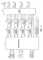
- Fig. 1 shows a system diagram of a microprocessor-based cardiac rhythm management device or pacemaker suitable for practicing the present invention.
- the device is equipped with multiple sensing and pacing channels which may be physically configured to sense and/or pace multiple sites in the atria or the ventricles.
- the controller 10 of the pacemaker is a microprocessor which communicates with a memory 12 via a bidirectional data bus.
- the memory 12 typically comprises a ROM (read-only memory) for program storage and a RAM (random-access memory) for data storage.
- the controller could be implemented by other types of logic circuitry (e.g., discrete components or programmable logic arrays) using a state machine type of design, but a microprocessor-based system is preferable.
- the term "circuitry” should be taken to refer to either discrete logic circuitry or to the programming of a microprocessor.
- sensing and pacing channels designated “a” through “d” comprising bipolar leads with ring electrodes 33a-d and tip electrodes 34a-d, sensing amplifiers 31a-d, pulse generators 32a-d, and channel interfaces 30a-d.
- Each channel thus includes a pacing channel made up of the pulse generator connected to the electrode and a sensing channel made up of the sense amplifier connected to the electrode.
- the channel interfaces 30a-d communicate bidirectionally with microprocessor 10, and each interface may include analog-to-digital converters for digitizing sensing signal inputs from the sensing amplifiers and registers that can be written to by the microprocessor in order to output pacing pulses, change the pacing pulse amplitude, and adjust the gain and threshold values for the sensing amplifiers.
- the sensing circuitry of the pacemaker detects a chamber sense, either an atrial sense or ventricular sense, when an electrogram signal (i.e., a voltage sensed by an electrode representing cardiac electrical activity) generated by a particular channel exceeds a specified detection threshold.
- Pacing algorithms used in particular pacing modes employ such senses to trigger or inhibit pacing, and the intrinsic atrial and/or ventricular rates can be detected by measuring the time intervals between atrial and ventricular senses, respectively.
- each bipolar lead is connected via conductors within the lead to a MOS switching network 70 controlled by the microprocessor.
- the switching network is used to switch the electrodes to the input of a sense amplifier in order to detect intrinsic cardiac activity and to the output of a pulse generator in order to deliver a pacing pulse.
- the switching network also enables the device to sense or pace either in a bipolar mode using both the ring and tip electrodes of a lead or in a unipolar mode using only one of the electrodes of the lead with the device housing or can 60 serving as a ground electrode.
- a shock pulse generator 50 is also interfaced to the controller for delivering a defibrillation shock via a pair of shock electrodes 51 to the atria or ventricles upon detection of a shockable tachyarrhythmia.
- the controller 10 controls the overall operation of the device in accordance with programmed instructions stored in memory, including controlling the delivery of paces via the pacing channels, interpreting sense signals received from the sensing channels, and implementing timers for defining escape intervals and sensory refractory periods.
- An exertion level sensor 330 e.g., an accelerometer, a minute ventilation sensor, or other sensor that measures a parameter related to metabolic demand
- a telemetry interface 40 is also provided which enables the controller to communicate with an external programmer.
- the controller is capable of operating the device in a number of programmed pacing modes which define how pulses are output in response to sensed events and expiration of time intervals.
- Most pacemakers for treating bradycardia are programmed to operate synchronously in a so-called demand mode where sensed cardiac events occurring within a defined interval either trigger or inhibit a pacing pulse.
- Inhibited demand pacing modes utilize escape intervals to control pacing in accordance with sensed intrinsic activity such that a pacing pulse is delivered to a heart chamber during a cardiac cycle only after expiration of a defined escape interval during which no intrinsic beat by the chamber is detected. Escape intervals for ventricular pacing can be restarted by ventricular or atrial events, the latter allowing the pacing to track intrinsic atrial beats.
- Multiple excitatory stimulation pulses can be delivered to multiple sites during a cardiac cycle in order to both pace the heart in accordance with a bradycardia mode and provide pre-excitation of selected sites.
- the device shown in Fig. 1 can be configured for stress reduction pacing such that one or more cardiac sites are sensed and/or paced in a manner that pre-excites at least one region of the myocardium that has been identified to be stressed and prone to the generation of arrhythmias.
- the device is configured to undergo a mode switch upon detection of a pre-arrhythmic condition to a stress reduction mode in which such stress reduction pacing is delivered.
- Switching to the stress reduction mode may include altering the device's pacing pulse output configuration and/or pulse output sequence in order to pre-excite a stressed myocardial region, where the pulse output configuration specifies a specific subset of the available electrodes to be used for delivering pacing pulses and the pulse output sequence specifies the timing relations between the pulses.
- the pulse output configuration is defined by the controller selecting particular pacing channels for use in outputting pacing pulses and by selecting particular electrodes for use by the channel with switch matrix 70.
- a switch to the stress reduction mode may also include adjusting one or more pacing parameters such as the escape intervals that determine pacing rate in order to pace the heart more frequently. In a normal operating mode, when no pre-arrhythmic condition is present, the device may either deliver no therapy at all or deliver a pacing therapy with a different pacing configuration, a different pulse output sequence, and/or different pacing parameter settings.
- Stressed myocardial sites to which pre-excitation pacing is to be applied in the stress reduction mode may be identified clinically by a variety of means, including anatomical information gained from imaging studies and electrophysiologic testing.
- the device shown in Fig. 1 can also be configured to determine the extent of stress at those sites where its sensing/pacing electrodes are disposed after implantation. It is known that the action potential duration of a myocardial fiber decreases with mechanical stress.
- the collective action potential duration of a myocardial region during systole also referred to herein as the activation-recovery interval, can be measured as the time between a detected depolarization and a detected repolarization in an electrogram generated by a sensing channel.
- Sensing channels can be designed to detect both depolarizations (i.e., conventional atrial or ventricular senses) and repolarizations.
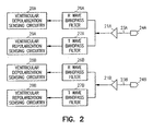
- Fig. 2 illustrates how this may be implemented in a ventricular sensing channel.
- the electrogram signal is passed through an R wave bandpass filter (26a or 26b) with passband characteristics selected to match the frequency content of a ventricular depolarization.
- the ventricular depolarization sensing circuitry (28a or 28b) then compares the filtered electrogram signal with a threshold to detect when a ventricular sense occurs.
- the channel awaits a ventricular repolarization during a specified time frame (e.g., between 50 and 500 milliseconds after the ventricular depolarization).
- a specified time frame e.g., between 50 and 500 milliseconds after the ventricular depolarization.
- the electrogram signal is passed through a T wave bandpass filter (27a or 27b) that has a passband characteristic conforming to the frequency content of a ventricular repolarization which is generally lower than that of a ventricular depolarization.
- the ventricular repolarization sensing circuitry (29a or 29b) then compares the filtered electrogram signal with a threshold to determine when the repolarization occurs.
- the channel may continue to monitor for depolarizations during this time in case the repolarization is undersensed.
- a similar scheme with atrial depolarization and repolarization bandpass filters and sensing circuits may be implemented to detect atrial repolarizations.
- the bandpass filters in Fig. 2 may be implemented as analog filters that operate directly on the electrogram signal received from the electrodes or may be switched capacitor-type filters that sample the electrogram signal into a discrete-time signal which is then filtered.
- the electrogram signal can be sampled and digitized by an A/D converter in the channel interface with the bandpass filtering implemented in the digital domain by a dedicated processor or code executed by the controller 10.
- sites that are stressed may be identified with a specified threshold criterion applied to the activation-recovery interval. That is, a site is identified as stressed when its measured activation-recovery interval is below the specified threshold value. Because the cardiac action potential normally varies with heart rate, it may be desirable to measure activation-recovery intervals during intrinsic beats for the purpose of assessing myocardial stress only when the heart rate is within a specified range. Activation-recovery intervals can also be measured during paced beats while pacing pulses are delivered at a specified rate.
- the depolarization corresponds to an evoked response detected by the sensing channel, while the repolarization is similar to an intrinsic beat.
- the threshold criterion for assessing myocardial wall stress based upon the activation-recovery interval may be adjusted in accordance with the measured intrinsic heart rate or pacing rate.
- a pre-arrhythmic condition for triggering the stress reduction mode is any condition deemed to increase the probability of an atrial or ventricualr arrhythmia occurring.
- the controller of the device may be programmed to detect such conditions form information gathered by the sensing channels used to detect cardiac activity as well as other available sensing modalities.
- the device may therefore be configured to switch to the stress reduction mode when the frequency of detected ectopic beats, such as pre-mature ventricular contractions or PVC's, rises above a specified threshold level.
- the level of sympathetic activity may be assessed by monitoring the heart rate via a ventricular sensing channel so that increased sympathetic activity is detected when the time interval between successive ventricular senses (i.e., RR intervals) falls below a specified minimum threshold value.
- the level of sympathetic activity may be more specifically assessed, however, by measuring the variability of the heart rate which is known to be influenced by the relative levels of sympathetic and parasympathetic activity. It has been found that spectral analysis of heart rate variability can be used to determine the relative levels of sympathetic and parasympathetic activity in a subject.
- Heart rate variability refers to the changes in heart rate that occur during a sinus rhythm (i.e., with normally activated and conducted heartbeats) and is primarily due to the interaction of the sympathetic and parasympathetic nervous systems.
- Low frequency variation in heart rate is due to both parasympathetic (or vagal) and sympathetic activity, while high frequency variation is primarily due to only parasympathetic activity.
- the ratio of low frequency variation to high frequency variation can thus be used as an indicator of the level of autonomic balance.
- the implanted device In order to perform spectral analysis of heart rate variability, the implanted device is programmed to measure and collect the time intervals between successive ventricular senses, referred to as RR intervals, for a period of time or a specified number of beats.
- the resulting series of RR interval values can then be stored as a discrete signal and either used directly as indexed by heartbeat or resampled at a specified sampling frequency in order to equalize the time intervals.
- the RR interval signal can then be analyzed to determine its energies in defined high and low frequency bands.
- the amount of signal power in a low frequency (LF) band ranging from 0.04 to 0.15 Hz is influenced by the levels of activity of both the sympathetic and parasympathetic nervous systems, while the amount of signal power in a high frequency band (HF) ranging from 0.15 to 0.40 Hz is primarily a function of parasympathetic activity.
- the ratio of the signal powers designated as the LF/HF ratio, is thus a good indicator of the state of autonomic balance, with a high LF/HF ratio indicating increased sympathetic activity, for example.
- spectral analysis of an RR interval signal can be performed directly in the frequency domain, a time-domain technique for determining the signal power in defined high and low frequency bands is preferably used for reasons of computational economy.
- a threshold level can then be defined for triggering the stress reduction mode.
- the pattern of electrical excitation of the human heart exhibits oscillations during successive heart beats.
- beat-to-beat oscillations may relate to the amplitude, duration, and/or morphology of myocardial action potentials as well as of externally recorded waveforms (e.g., an EKG) that reflect the depolarization and repolarization of the myocardium during a heart beat.
- This phenomena is referred to as electrical altemans and is usually indicative of a pathological state in which potentially dangerous cardiac arrhythmias are more likely to occur.
- the presence of electrical alternans may thus be used as a pre-arrhythmic condition for triggering the stress reduction mode, with the implantable cardiac rhythm management device configured to utilize its sensing channels to detect such electrical alternans.
- the sensing channels produce electrogram signals that reflect the electrical activity at a local cardiac site near which a sensing electrode is disposed, and such local electrical activity exhibits oscillations during electrical alternans.
- the device detects the start of depolarization and the end of repolarization (i.e., corresponding to the Q wave and T wave, respectively, in a surface EKG) in an electrogram signal from a ventricular sensing channel and measures the time interval therebetween. The interval so measured corresponds to the action potential duration of the local cardiac site.
- the device may then detect the presence of electrical altemans when the difference between intervals measured during successive heart beats exceeds a specified threshold value and the difference persists for a specified length of time or number of beats.
- Other embodiments may process the electrogram signal to determine if oscillations exist with respect to other features such as amplitude or waveform morphology and then detect electrical altemans if the oscillations are of sufficient magnitude and duration. Electrical altemans may also be detected by processing of electrogram signals from atrial sensing channels.
- Fig. 3 shows an exemplary algorithm for detecting electrical alternans based upon measurement of the R-T interval that can be implemented by the controller.
- the device waits for an R wave (i.e., a ventricular sense).
- an R wave i.e., a ventricular sense
- the device looks for a T wave in the ventricular sensing channel during an appropriate time window at step S2.
- the time interval between the two is measured at step S3.
- the difference between the R-T interval of the present cardiac cycle and the R-T interval of the previous cardiac cycle is then computed at step S4.
- step S5 If the R-T interval difference exceeds a specified threshold, as determined at step S5, a counter that keeps track of the number of consecutive R-T interval differences that exceed the threshold is incremented at step S8. Otherwise, a condition of no electrical altemans is detected at step S6, the counter is reset at step S7, and the device waits for the next R wave at step S1. If the R-T interval difference does exceed the threshold, after incrementing the counter at step S8, the counter's value is compared to a threshold count value at step S9. The threshold count value specifies the number of consecutive heart beats that the R-T interval difference must be above threshold before electrical alternans is detected. If the count exceeds the count threshold value, electrical altemans is detected at step S10. The device then returns to step S1 and measures the next R-T interval.
- Electrical alternans is also highly correlated to oscillations in the mechanical function of the heart that result in alternations in pulse pressure, referred to as pulsus alternans. Since the pumping action of the heart is due to the electromechanical coupling between electrical depolarization of myocardial cells and their mechanical contraction, electrical altemans and pulsus altemans may be different manifestations of the same underlying phenomena in certain cases. Another way of detecting electrical alternans, therefore, is for a properly equipped implantable device to measure parameters reflective of pulse pressure in order to ascertain if oscillations exist in those parameters. Such parameters may include the intensity of heart sounds as measured by an accelerometer and stroke volume as measured by an impedance measuring circuit.
- one or more myocardial pacing sites identified as stressed may be mechanically unloaded during systole by delivering one or more pacing pulses in a manner such that the stressed site or sites are pre-excited relative to other regions of the myocardium.
- Pacing for myocardial wall stress reduction in order to prevent arrhythmias may be delivered in accordance with a programmed bradycardia pacing mode and thus also provide therapy for bradycardia as well.
- Such pacing also may or may not include multi-site pacing for purpose of also providing cardiac resynchronization therapy.
- What effects localized stress reduction is the pre-excitation of one or more myocardial regions relative to other regions during systole. This may be accomplished in certain situations with single-site pacing and in others with multi-site resynchronization pacing that also improves the pumping function of the heart. In the latter case, the pacing pulse output configuration and sequence that produces optimum resynchronization may or may not also deliver optimum therapy for reduction of myocardial wall stress.
- a device such as illustrated in Fig. 1 is configured with a plurality of pacing/sensing electrodes disposed in both ventricles at selected electrode sites so that pre-excitation pacing may be delivered to one or more of those sites in order to prevent ventricular arrhythmias.
- Alternative embodiments may be configured to deliver pre-excitation pacing to atrial sites in order to prevent atrial arrhythmias.
- the device may be programmed in a normal pacing mode to deliver pacing pulses to selected ones of the available pacing electrodes, referred to as a pulse output configuration, and in a specified time sequence, referred to as a pulse output sequence.
- the device Upon detection of a pre-arrhythmic condition, the device is programmed to initiate stress reduction pacing at selected one or ones of the available electrode sites that have been pre-identified as stressed sites.
- Switching to the stress reduction mode may include modifying the pulse output configuration by selecting different pacing channels and/or electrodes via switch matrix 70 for use in delivering pacing pulses from those used in the normal mode. For example, a pace may be delivered to a different site by interchanging which electrodes of a bipolar lead are the cathode and anode during bipolar pacing.
- the stress reduction mode may also have a different pulse output sequence in order to achieve the desired pre-excitation at a stressed site.
- the stress reduction mode may also include an adjustment of one or more of the escape intervals used in the particular bradycardia pacing mode employed to deliver pre-excitation paces to the ventricular sites such as a ventricular escape interval or an atrio-ventricular interval in the case of an atrial-tracking pacing mode.
- the escape intervals are adjusted in the stress reduction mode so that the pacing rate is above the measured intrinsic rate.
- overdrive pacing increases the frequency of paced cycles and hence increases the effectiveness of the stress reduction therapy in preventing arrhythmias.
- the device normally delivers bradycardia pacing at a single ventricular site.
- the device switches the pacing configuration to deliver pacing pulses to another electrode site that has been identified as a stressed site. Single-site pacing that pre-excites the ventricle at this site results in the stressed site being excited before other regions of the ventricular myocardium as the wave of excitation spreads from the paced site.
- the device is programmed in the normal mode to deliver resynchronization pacing with multiple paces delivered to one or both ventricles during a cardiac cycle.
- the pulse output configuration is modified, if necessary, to include one or more stressed sites, and the pulse output sequence is selected such that the stressed site or sites are excited before other regions as the wave of excitation spreads from the multiple pacing sites.
Abstract
Description
- This invention pertains to apparatus and methods for the diagnosis and treatment of heart disease and to devices providing electrostimulation to the heart such as cardiac pacemakers.
- Tachyarrhythmias are abnormal heart rhythms characterized by a rapid heart rate, typically expressed in units of beats per minute (bpm). They can occur in either chamber of the heart (i.e., ventricles or atria) or both. Examples of tachyarrhythmias include sinus tachycardia, ventricular tachycardia, ventricular fibrillation (VF), atrial tachycardia, and atrial fibrillation (AF). Tachyarrhythmias can be due to abnormal excitation by normal pacemaker tissue, an ectopic excitatory focus, or a re-entry phenomenon. Tachycardia occurs when the heart contracts relatively normally but at a rapid rate, while fibrillation occurs when the chamber depolarizes in a chaotic fashion with abnormal depolarization waveforms as reflected by an EKG.
- An electrical defibrillation shock applied to a heart chamber can be used to terminate most tachyarrhythmias by depolarizing excitable myocardium and rendering it refractory. Implantable cardioverter/defibrillators (ICDs) provide this kind of therapy by delivering a shock pulse to the heart when fibrillation is detected by the device. ICDs can be designed to treat either atrial or ventricular tachyarrhythmias, or both, and may also incorporate cardiac pacing functionality. The most dangerous tachyarrhythmias are ventricular tachycardia and ventricular fibrillation, and ICDs have most commonly been applied in the treatment of those conditions. Another type of electrical therapy for tachycardia is anti-tachycardia pacing (ATP). In ATP, the heart is competitively paced with one or more pacing pulses in an effort to interrupt the reentrant circuit causing the tachycardia. Modem ICD's usually have ATP capability so that ATP therapy is delivered to the heart when a tachycardia is detected, while a shock pulse is delivered when fibrillation occurs.
- ICDs are also capable of detecting atrial tachyarrhythmias, such as atrial fibrillation and atrial flutter, and delivering a shock pulse to the atria in order to terminate the arrhythmia. Although not immediately life-threatening, it is important to treat atrial fibrillation for several reasons. First, atrial fibrillation is associated with a loss of atrio-ventricular synchrony which can be hemodynamically compromising and cause such symptoms as dyspnea, fatigue, vertigo, and angina. Atrial fibrillation can also predispose to strokes resulting from emboli forming in the left atrium. Although drug therapy and/or in-hospital cardioversion are acceptable treatment modalities for atrial fibrillation, ICDs configured to treat atrial fibrillation offer a number of advantages to certain patients, including convenience and greater efficacy.
- As described above, an implantable cardiac rhythm management device may deliver appropriate therapy to terminate certain detected arrhythmia. Such therapies are not invariably successful, however, and, even when they are, may , require repeated application until the arrhythmia is finally terminated. Defibrillation shocks also subject the patient to some discomfort. It would be more beneficial if an implantable device could detect when a pre-arrhythmic condition exists and deliver electro-stimulatory therapy in a manner that prevents the arrhythmia from occurring in the first instance.
- One factor responsible for the initiation of arrhythmias in the heart is the mechanical stress exerted on vulnerable regions of the heart during systolic contraction. The present invention relates to an apparatus and method for relieving such stresses by applying pacing therapy in a manner that mechanically unloads one or more selected myocardial regions during systole relative to other regions. Disparate stresses in different areas of the heart are also responsible for undesirable myocardial remodeling in heart failure patients. Although pacing therapy to unload stressed myocardial regions may be beneficial in preventing or reversing such remodeling, it may not be desirable to continually employ such pacing therapy in certain patients because that may not be the most hemodynamically effective way for the heart to beat. It may also not be desirable to continuously pace at a pacing rate that is optimal for relieving myocardial wall stress in order to prevent arrhythmias. In accordance with the present invention, a cardiac rhythm management device is configured to switch to a stress reduction mode and deliver pacing therapy which mechanically unloads one or more identified stressed myocardial regions upon detection of a pre-arrhythmic condition. When no such pre-arrhythmic condition exists, the device may employ another mode of pacing, such as conventional bradycardia or resynchronization pacing, or may not deliver any pacing therapy at all.
-
-
Fig. 1 is a block diagram of an exemplary cardiac rhythm management device for practicing the present invention. -
Fig. 2 is a block diagram of sensing channel components for detecting ventricular depolarizations and repolarizations. -
Fig. 3 illustrates an exemplary implementation of an algorithm for detecting electrical alternans. - It is known that in certain patients, cardiac arrhythmias tend to arise in particular myocardial regions when those regions are subjected to mechanical and/or hypoxic stresses such as occur during systolic contractions. In accordance with the present invention, multi-site pacing is used to change the distribution of wall stress experienced by the ventricle during systole in order to mechanically unload those vulnerable regions and render them less likely to initiate an arrhythmia. An implanted cardiac rhythm management device may be configured to deliver such pacing therapy in response to the occurrence of a pre-arrhythmic condition as detected by a variety of means.
- Prior devices have utilized multi-site pacing to redistribute myocardial wall stress for the purpose of preventing or reversing cardiac remodeling (e.g., see
US 2003/161410 ). Devices have also been configured to detect pre-arrhythmic conditions (e.g., seeEP-A-1 197 243 ), accordingly to the preamble of claim 1. Heretofore, however, there has not been a device configured to deliver pacing in a stress reduction mode for the purpose of reducing the probability of an arrhythmia occurring or a device configured to deliver pacing in a mode that reduces the stress of selected myocardial sites in response to detection of a pre-arrhythmic condition. - The degree to which a heart muscle fiber is stretched before it contracts is termed the preload. The maximum tension and velocity of shortening of a muscle fiber increases with increasing preload. The increase in contractile response of the heart with increasing preload is known as the Frank-Starling principle. When a myocardial region contracts late relative to other regions; the earlier contraction of opposing regions stretches the later contracting region and increases its preload. The degree of tension or stress on a heart muscle fiber as it contracts is termed the afterload. Because pressure within the ventricles rises rapidly from a diastolic to a systolic value as blood is pumped out into the aorta and pulmonary arteries, the part of the ventricle that first contracts does so against a lower afterload than does a part of the ventricle contracting later. Thus, a myocardial region that contracts earlier than other regions during systole is subjected to both a decreased preload and a decreased afterload. What is referred to herein as stress reduction pacing or pre-excitation pacing makes use of this phenomena in order to redistribute myocardial wall stress during systole by pacing one or more sites in a ventricle (or an atrium) with one or more pacing pulses delivered in a specified pulse output sequence. The pace or paces are delivered in a manner that excites a previously stressed region of the myocardium earlier during systole so that it experiences less afterload and preload. This pre-excitation of the previously stressed region relative to other regions unloads the region from mechanical stress, making it less likely that the cells in that region will exhibit inherent intrinsic activity and cause an arrhythmia. An increased preload and afterload also requires an increased energy expenditure by the muscle which, in turn, increases its perfusion requirements and may result in ischemia. Pre-excitation of an ischemic region may thus reduce the region's need for blood as well as reduce the mechanical stress to which the region is subjected during systole to reduce the likelihood of an arrhythmia.
- Pre-excitation pacing can also have a beneficial effect in the treatment of heart failure. The conduction delays associated with heart failure and ventricular dysfunction cause different regions of the myocardium to contract later than others and thus subject those regions to increased stress during systole. The heart's initial physiological response to the uneven stress resulting from an increased preload and afterload is compensatory hypertrophy in those later contracting regions of the myocardium. In the later stages of remodeling, the regions may undergo atrophic changes with wall thinning due to the increased stress. This process is referred to as cardiac remodeling and is strongly associated with increased mortality in heart failure patients. In addition to its anti-arrhythmic effects, pre-excitation pacing of previously stressed or hypertrophied myocardial regions may also prevent or reverse such remodeling.
- Pre-excitation pacing as described above is preferably delivered in conjunction with a conventional synchronous pacing mode such as used for treating bradycardia. If functioning properly, an implanted pacemaker makes up for the heart's inability to pace itself at an appropriate rhythm in order to meet metabolic demand by enforcing a minimum heart rate. Cardiac rhythm management devices have also been developed for the treatment of heart failure that provide multi-site pacing stimulation to one or more heart chambers in an attempt to improve the coordination of atrial and/or ventricular contractions, termed cardiac resynchronization therapy. In multi-site resynchronization pacing, the atria or ventricles are paced at more than one site in order to affect a spread of excitation that results in a more coordinated contraction. Biventricular pacing is one example of multi-site pacing in which both ventricles are paced in order to synchronize their respective contractions.
- A patient suitable for treatment with pre-excitation pacing therapy for arrhythmia prevention may also benefit from bradycardia and/or resynchronization pacing. In those situations, however, the optimum manner for delivering bradycardia or resynchronization therapies in any particular patient may be inconsistent with the optimum manner for delivering pre-excitation pacing in order to prevent arrhythmias. In the case of resynchronization pacing, the particular pacing sites and pacing pulse timing used to improve the hemodynamics of a heart failure patient may be different than the pacing sites and pacing pulse timing for optimal application pre-excitation therapy to prevent arrhythmias. For example, a more hemodynamically effective contraction may be obtained by exciting a number of selected pacing sites simultaneously in some patients, which may not result in the pre-excitation of previously stressed myocardium. Pre-excitation pacing is also only effective during cardiac cycles in which pre-excitation paces are delivered. Pre-excitation pacing is thus optimally delivered in conjunction with a synchronous bradycardia pacing mode where the escape interval or intervals are such that the pacing rate is greater than the intrinsic heart rate. It may not be desirable, however, to employ such overdrive pacing on a continuous basis. It may not even be desirable for some patients to be paced at all on a continuous basis. To deal with these situations, a cardiac rhythm management device as described below may be configured to deliver optimal pre-excitation therapy for arrhythmia prevention only upon detection of a pre-arrhythmic condition.
- Cardiac rhythm management devices such as pacemakers are usually implanted subcutaneously on a patient's chest and have leads threaded intravenously into the heart to connect the device to electrodes used for sensing and pacing. A programmable electronic controller causes the pacing pulses to be output in response to lapsed time intervals and sensed electrical activity (i.e., intrinsic heart beats not as a result of a pacing pulse). Pacemakers sense intrinsic cardiac electrical activity by means of internal electrodes disposed near the chamber to be sensed. A depolarization wave associated with an intrinsic contraction of the atria or ventricles that is detected by the pacemaker is referred to as an atrial sense or ventricular sense, respectively. In order to cause such a contraction in the absence of an intrinsic beat, a pacing pulse (either an atrial pace or a ventricular pace) with energy above a certain pacing threshold is delivered to the chamber.
-
Fig. 1 shows a system diagram of a microprocessor-based cardiac rhythm management device or pacemaker suitable for practicing the present invention. The device is equipped with multiple sensing and pacing channels which may be physically configured to sense and/or pace multiple sites in the atria or the ventricles. Thecontroller 10 of the pacemaker is a microprocessor which communicates with amemory 12 via a bidirectional data bus. Thememory 12 typically comprises a ROM (read-only memory) for program storage and a RAM (random-access memory) for data storage. The controller could be implemented by other types of logic circuitry (e.g., discrete components or programmable logic arrays) using a state machine type of design, but a microprocessor-based system is preferable. As used herein, the term "circuitry" should be taken to refer to either discrete logic circuitry or to the programming of a microprocessor. - Shown in the figure are four exemplary sensing and pacing channels designated "a" through "d" comprising bipolar leads with ring electrodes 33a-d and tip electrodes 34a-d, sensing amplifiers 31a-d, pulse generators 32a-d, and channel interfaces 30a-d. Each channel thus includes a pacing channel made up of the pulse generator connected to the electrode and a sensing channel made up of the sense amplifier connected to the electrode. The channel interfaces 30a-d communicate bidirectionally with
microprocessor 10, and each interface may include analog-to-digital converters for digitizing sensing signal inputs from the sensing amplifiers and registers that can be written to by the microprocessor in order to output pacing pulses, change the pacing pulse amplitude, and adjust the gain and threshold values for the sensing amplifiers. The sensing circuitry of the pacemaker detects a chamber sense, either an atrial sense or ventricular sense, when an electrogram signal (i.e., a voltage sensed by an electrode representing cardiac electrical activity) generated by a particular channel exceeds a specified detection threshold. Pacing algorithms used in particular pacing modes employ such senses to trigger or inhibit pacing, and the intrinsic atrial and/or ventricular rates can be detected by measuring the time intervals between atrial and ventricular senses, respectively. - The electrodes of each bipolar lead are connected via conductors within the lead to a
MOS switching network 70 controlled by the microprocessor. The switching network is used to switch the electrodes to the input of a sense amplifier in order to detect intrinsic cardiac activity and to the output of a pulse generator in order to deliver a pacing pulse. The switching network also enables the device to sense or pace either in a bipolar mode using both the ring and tip electrodes of a lead or in a unipolar mode using only one of the electrodes of the lead with the device housing or can 60 serving as a ground electrode. As explained below, one way in which the device may alter the spatial distribution of pacing is to switch from unipolar to bipolar pacing (or vice-versa) or to interchange which electrodes of a bipolar lead are the cathode and anode during bipolar pacing. Ashock pulse generator 50 is also interfaced to the controller for delivering a defibrillation shock via a pair ofshock electrodes 51 to the atria or ventricles upon detection of a shockable tachyarrhythmia. - The
controller 10 controls the overall operation of the device in accordance with programmed instructions stored in memory, including controlling the delivery of paces via the pacing channels, interpreting sense signals received from the sensing channels, and implementing timers for defining escape intervals and sensory refractory periods. An exertion level sensor 330 (e.g., an accelerometer, a minute ventilation sensor, or other sensor that measures a parameter related to metabolic demand) enables the controller to adapt the pacing rate in accordance with changes in the patient's physical activity. Atelemetry interface 40 is also provided which enables the controller to communicate with an external programmer. - The controller is capable of operating the device in a number of programmed pacing modes which define how pulses are output in response to sensed events and expiration of time intervals. Most pacemakers for treating bradycardia are programmed to operate synchronously in a so-called demand mode where sensed cardiac events occurring within a defined interval either trigger or inhibit a pacing pulse. Inhibited demand pacing modes utilize escape intervals to control pacing in accordance with sensed intrinsic activity such that a pacing pulse is delivered to a heart chamber during a cardiac cycle only after expiration of a defined escape interval during which no intrinsic beat by the chamber is detected. Escape intervals for ventricular pacing can be restarted by ventricular or atrial events, the latter allowing the pacing to track intrinsic atrial beats. Multiple excitatory stimulation pulses can be delivered to multiple sites during a cardiac cycle in order to both pace the heart in accordance with a bradycardia mode and provide pre-excitation of selected sites.
- The device shown in
Fig. 1 can be configured for stress reduction pacing such that one or more cardiac sites are sensed and/or paced in a manner that pre-excites at least one region of the myocardium that has been identified to be stressed and prone to the generation of arrhythmias. In accordance with the invention, the device is configured to undergo a mode switch upon detection of a pre-arrhythmic condition to a stress reduction mode in which such stress reduction pacing is delivered. - Switching to the stress reduction mode may include altering the device's pacing pulse output configuration and/or pulse output sequence in order to pre-excite a stressed myocardial region, where the pulse output configuration specifies a specific subset of the available electrodes to be used for delivering pacing pulses and the pulse output sequence specifies the timing relations between the pulses. The pulse output configuration is defined by the controller selecting particular pacing channels for use in outputting pacing pulses and by selecting particular electrodes for use by the channel with
switch matrix 70. A switch to the stress reduction mode may also include adjusting one or more pacing parameters such as the escape intervals that determine pacing rate in order to pace the heart more frequently. In a normal operating mode, when no pre-arrhythmic condition is present, the device may either deliver no therapy at all or deliver a pacing therapy with a different pacing configuration, a different pulse output sequence, and/or different pacing parameter settings. - Stressed myocardial sites to which pre-excitation pacing is to be applied in the stress reduction mode may be identified clinically by a variety of means, including anatomical information gained from imaging studies and electrophysiologic testing. The device shown in
Fig. 1 can also be configured to determine the extent of stress at those sites where its sensing/pacing electrodes are disposed after implantation. It is known that the action potential duration of a myocardial fiber decreases with mechanical stress. The collective action potential duration of a myocardial region during systole, also referred to herein as the activation-recovery interval, can be measured as the time between a detected depolarization and a detected repolarization in an electrogram generated by a sensing channel. Sensing channels can be designed to detect both depolarizations (i.e., conventional atrial or ventricular senses) and repolarizations.Fig. 2 illustrates how this may be implemented in a ventricular sensing channel. When the channel is awaiting a ventricular sense, the electrogram signal is passed through an R wave bandpass filter (26a or 26b) with passband characteristics selected to match the frequency content of a ventricular depolarization. The ventricular depolarization sensing circuitry (28a or 28b) then compares the filtered electrogram signal with a threshold to detect when a ventricular sense occurs. After a ventricular sense occurs, the channel awaits a ventricular repolarization during a specified time frame (e.g., between 50 and 500 milliseconds after the ventricular depolarization). During this time, the electrogram signal is passed through a T wave bandpass filter (27a or 27b) that has a passband characteristic conforming to the frequency content of a ventricular repolarization which is generally lower than that of a ventricular depolarization. The ventricular repolarization sensing circuitry (29a or 29b) then compares the filtered electrogram signal with a threshold to determine when the repolarization occurs. The channel may continue to monitor for depolarizations during this time in case the repolarization is undersensed. A similar scheme with atrial depolarization and repolarization bandpass filters and sensing circuits may be implemented to detect atrial repolarizations. - The bandpass filters in
Fig. 2 may be implemented as analog filters that operate directly on the electrogram signal received from the electrodes or may be switched capacitor-type filters that sample the electrogram signal into a discrete-time signal which is then filtered. Alternatively, the electrogram signal can be sampled and digitized by an A/D converter in the channel interface with the bandpass filtering implemented in the digital domain by a dedicated processor or code executed by thecontroller 10. - After measuring the activation-recovery interval at a plurality of myocardial sites, sites that are stressed may be identified with a specified threshold criterion applied to the activation-recovery interval. That is, a site is identified as stressed when its measured activation-recovery interval is below the specified threshold value. Because the cardiac action potential normally varies with heart rate, it may be desirable to measure activation-recovery intervals during intrinsic beats for the purpose of assessing myocardial stress only when the heart rate is within a specified range. Activation-recovery intervals can also be measured during paced beats while pacing pulses are delivered at a specified rate. In the case of a paced beat, the depolarization corresponds to an evoked response detected by the sensing channel, while the repolarization is similar to an intrinsic beat. Alternatively, the threshold criterion for assessing myocardial wall stress based upon the activation-recovery interval may be adjusted in accordance with the measured intrinsic heart rate or pacing rate.
- A pre-arrhythmic condition for triggering the stress reduction mode is any condition deemed to increase the probability of an atrial or ventricualr arrhythmia occurring. As described below, the controller of the device may be programmed to detect such conditions form information gathered by the sensing channels used to detect cardiac activity as well as other available sensing modalities.
- An increase in the frequency of ectopic heart beats is known to precede the development of arrhythmias in certain circumstances. The device may therefore be configured to switch to the stress reduction mode when the frequency of detected ectopic beats, such as pre-mature ventricular contractions or PVC's, rises above a specified threshold level.
- It is well-known that an increase in the activity of the sympathetic nervous system can make the onset of such arrhythmias more likely and may serve as a trigger for such events in certain patients. The level of sympathetic activity may be assessed by monitoring the heart rate via a ventricular sensing channel so that increased sympathetic activity is detected when the time interval between successive ventricular senses (i.e., RR intervals) falls below a specified minimum threshold value. The level of sympathetic activity may be more specifically assessed, however, by measuring the variability of the heart rate which is known to be influenced by the relative levels of sympathetic and parasympathetic activity. It has been found that spectral analysis of heart rate variability can be used to determine the relative levels of sympathetic and parasympathetic activity in a subject. Heart rate variability refers to the changes in heart rate that occur during a sinus rhythm (i.e., with normally activated and conducted heartbeats) and is primarily due to the interaction of the sympathetic and parasympathetic nervous systems. Low frequency variation in heart rate is due to both parasympathetic (or vagal) and sympathetic activity, while high frequency variation is primarily due to only parasympathetic activity. The ratio of low frequency variation to high frequency variation can thus be used as an indicator of the level of autonomic balance.
- In order to perform spectral analysis of heart rate variability, the implanted device is programmed to measure and collect the time intervals between successive ventricular senses, referred to as RR intervals, for a period of time or a specified number of beats. The resulting series of RR interval values can then be stored as a discrete signal and either used directly as indexed by heartbeat or resampled at a specified sampling frequency in order to equalize the time intervals. The RR interval signal can then be analyzed to determine its energies in defined high and low frequency bands. It has been found that the amount of signal power in a low frequency (LF) band ranging from 0.04 to 0.15 Hz is influenced by the levels of activity of both the sympathetic and parasympathetic nervous systems, while the amount of signal power in a high frequency band (HF) ranging from 0.15 to 0.40 Hz is primarily a function of parasympathetic activity. The ratio of the signal powers, designated as the LF/HF ratio, is thus a good indicator of the state of autonomic balance, with a high LF/HF ratio indicating increased sympathetic activity, for example. Although spectral analysis of an RR interval signal can be performed directly in the frequency domain, a time-domain technique for determining the signal power in defined high and low frequency bands is preferably used for reasons of computational economy. However, the state of autonomic balance is assessed, a threshold level can then be defined for triggering the stress reduction mode.
- Under certain circumstances, the pattern of electrical excitation of the human heart exhibits oscillations during successive heart beats. Such beat-to-beat oscillations may relate to the amplitude, duration, and/or morphology of myocardial action potentials as well as of externally recorded waveforms (e.g., an EKG) that reflect the depolarization and repolarization of the myocardium during a heart beat. This phenomena is referred to as electrical altemans and is usually indicative of a pathological state in which potentially dangerous cardiac arrhythmias are more likely to occur. The presence of electrical alternans may thus be used as a pre-arrhythmic condition for triggering the stress reduction mode, with the implantable cardiac rhythm management device configured to utilize its sensing channels to detect such electrical alternans. The sensing channels produce electrogram signals that reflect the electrical activity at a local cardiac site near which a sensing electrode is disposed, and such local electrical activity exhibits oscillations during electrical alternans. In one embodiment, the device detects the start of depolarization and the end of repolarization (i.e., corresponding to the Q wave and T wave, respectively, in a surface EKG) in an electrogram signal from a ventricular sensing channel and measures the time interval therebetween. The interval so measured corresponds to the action potential duration of the local cardiac site. The device may then detect the presence of electrical altemans when the difference between intervals measured during successive heart beats exceeds a specified threshold value and the difference persists for a specified length of time or number of beats. Other embodiments may process the electrogram signal to determine if oscillations exist with respect to other features such as amplitude or waveform morphology and then detect electrical altemans if the oscillations are of sufficient magnitude and duration. Electrical altemans may also be detected by processing of electrogram signals from atrial sensing channels.
-
Fig. 3 shows an exemplary algorithm for detecting electrical alternans based upon measurement of the R-T interval that can be implemented by the controller. At step S1, the device waits for an R wave (i.e., a ventricular sense). When an R wave is detected, the device then looks for a T wave in the ventricular sensing channel during an appropriate time window at step S2. When both R and T waves are detected during a cardiac cycle, the time interval between the two is measured at step S3. The difference between the R-T interval of the present cardiac cycle and the R-T interval of the previous cardiac cycle is then computed at step S4. If the R-T interval difference exceeds a specified threshold, as determined at step S5, a counter that keeps track of the number of consecutive R-T interval differences that exceed the threshold is incremented at step S8. Otherwise, a condition of no electrical altemans is detected at step S6, the counter is reset at step S7, and the device waits for the next R wave at step S1. If the R-T interval difference does exceed the threshold, after incrementing the counter at step S8, the counter's value is compared to a threshold count value at step S9. The threshold count value specifies the number of consecutive heart beats that the R-T interval difference must be above threshold before electrical alternans is detected. If the count exceeds the count threshold value, electrical altemans is detected at step S10. The device then returns to step S1 and measures the next R-T interval. - Electrical alternans is also highly correlated to oscillations in the mechanical function of the heart that result in alternations in pulse pressure, referred to as pulsus alternans. Since the pumping action of the heart is due to the electromechanical coupling between electrical depolarization of myocardial cells and their mechanical contraction, electrical altemans and pulsus altemans may be different manifestations of the same underlying phenomena in certain cases. Another way of detecting electrical alternans, therefore, is for a properly equipped implantable device to measure parameters reflective of pulse pressure in order to ascertain if oscillations exist in those parameters. Such parameters may include the intensity of heart sounds as measured by an accelerometer and stroke volume as measured by an impedance measuring circuit.
- As described above, one or more myocardial pacing sites identified as stressed may be mechanically unloaded during systole by delivering one or more pacing pulses in a manner such that the stressed site or sites are pre-excited relative to other regions of the myocardium. Such pacing subjects the stressed sites to a lessened preload and afterload during systole, thus reducing the wall stress. Pacing for myocardial wall stress reduction in order to prevent arrhythmias may be delivered in accordance with a programmed bradycardia pacing mode and thus also provide therapy for bradycardia as well. Such pacing also may or may not include multi-site pacing for purpose of also providing cardiac resynchronization therapy. What effects localized stress reduction is the pre-excitation of one or more myocardial regions relative to other regions during systole. This may be accomplished in certain situations with single-site pacing and in others with multi-site resynchronization pacing that also improves the pumping function of the heart. In the latter case, the pacing pulse output configuration and sequence that produces optimum resynchronization may or may not also deliver optimum therapy for reduction of myocardial wall stress.
- In an exemplary embodiment, a device such as illustrated in
Fig. 1 is configured with a plurality of pacing/sensing electrodes disposed in both ventricles at selected electrode sites so that pre-excitation pacing may be delivered to one or more of those sites in order to prevent ventricular arrhythmias. Alternative embodiments may be configured to deliver pre-excitation pacing to atrial sites in order to prevent atrial arrhythmias. The device may be programmed in a normal pacing mode to deliver pacing pulses to selected ones of the available pacing electrodes, referred to as a pulse output configuration, and in a specified time sequence, referred to as a pulse output sequence. Upon detection of a pre-arrhythmic condition, the device is programmed to initiate stress reduction pacing at selected one or ones of the available electrode sites that have been pre-identified as stressed sites. Switching to the stress reduction mode may include modifying the pulse output configuration by selecting different pacing channels and/or electrodes viaswitch matrix 70 for use in delivering pacing pulses from those used in the normal mode. For example, a pace may be delivered to a different site by interchanging which electrodes of a bipolar lead are the cathode and anode during bipolar pacing. The stress reduction mode may also have a different pulse output sequence in order to achieve the desired pre-excitation at a stressed site. The stress reduction mode may also include an adjustment of one or more of the escape intervals used in the particular bradycardia pacing mode employed to deliver pre-excitation paces to the ventricular sites such as a ventricular escape interval or an atrio-ventricular interval in the case of an atrial-tracking pacing mode. The escape intervals are adjusted in the stress reduction mode so that the pacing rate is above the measured intrinsic rate. Such overdrive pacing increases the frequency of paced cycles and hence increases the effectiveness of the stress reduction therapy in preventing arrhythmias. - In one example, the device normally delivers bradycardia pacing at a single ventricular site. Upon initiation of the stress reduction mode, the device switches the pacing configuration to deliver pacing pulses to another electrode site that has been identified as a stressed site. Single-site pacing that pre-excites the ventricle at this site results in the stressed site being excited before other regions of the ventricular myocardium as the wave of excitation spreads from the paced site. In another example, the device is programmed in the normal mode to deliver resynchronization pacing with multiple paces delivered to one or both ventricles during a cardiac cycle. Upon switching to the stress reduction mode, the pulse output configuration is modified, if necessary, to include one or more stressed sites, and the pulse output sequence is selected such that the stressed site or sites are excited before other regions as the wave of excitation spreads from the multiple pacing sites.
- Although the invention has been described in conjunction with the foregoing specific embodiments, many alternatives, variations, and modifications will be apparent to those of ordinary skill in the art. Other such alternatives, variations, and modifications are intended to fall within the scope of the following appended claims.
Claims (9)
- A cardiac rhythm management device, comprising:sensing channels (34a-d, 33a-d, 31a-d, 30a-d) for sensing cardiac electrical activity at a plurality of myocardial sites;pacing channels (34a-d, 33a-d, 32a-d, 30a-d) for delivering pacing pulses to one or more of the plurality of myocardial sites;a controller (10) for controlling the delivery of pacing pulses in accordance with a programmed pacing mode;circuitry (10) for detecting a pre-arrhythmic condition; and,the device being further characterized by:circuitry (10) for switching an operating mode of the device from a normal mode to a stress reduction mode upon detection of a pre-arrhythmic condition, where the stress reduction mode delivers pacing to particular selected myocardial sites in a manner that pre-excites the selected sites to an extent greater than the normal mode, and where the selected myocardial sites may be identified as stressed sites so that the stress reduction mode reduces myocardial wall stress at the stressed sites.
- The device of claim 1 wherein the circuitry for switching to a stress reduction mode modifies a pulse output sequence that defines an order in which pacing pulses are output during a pacing cycle, where modified pulse output sequence excites an identified stressed myocardial site before other myocardial regions during systole.
- The device of claim 1 wherein the circuitry for switching to a stress reduction mode modifies a pulse output configuration that defines which pacing channels are used during a pacing cycle such that an identified stressed site is excited before other myocardial regions during systole.
- The device of claim 2 wherein the circuitry for switching to a stress reduction mode.modifies one or more pacing parameters in order to increase the frequency of pacing.
- The device of claim 1 wherein the circuitry for detecting a pre-arrhythmic condition is circuitry for detecting electrical alternans.
- The device of claim 1 wherein the circuitry for detecting a pre-arrhythmic condition is circuitry for performing spectral analysis of heart rate variability.
- The device of claim 1 wherein the circuitry for detecting a pre-arrhythmic condition is circuitry for measuring ectopic beat frequency.
- The device of claim 1 further comprising:circuitry (10) for measuring activation-recovery intervals at a plurality of myocardial sites indicative of myocardial wall stress; and,circuitry (10) for identifying one or more stressed myocardial sites based upon the measured activation-recovery intervals.
- The device of claim 8 further comprising circuitry (10) for measuring an activation-recovery interval as the time between a detected depolarization and a detected repolarization in an electrogram generated by a sensing channel.
Applications Claiming Priority (3)
| Application Number | Priority Date | Filing Date | Title |
|---|---|---|---|
| US298156 | 1989-01-17 | ||
| US10/298,156 US7065405B2 (en) | 2002-11-15 | 2002-11-15 | Stress reduction pacing mode for arrhythmia prevention |
| PCT/US2003/036681 WO2004045710A1 (en) | 2002-11-15 | 2003-11-14 | Stress reduction pacing mode for arrhythmia prevention |
Publications (2)
| Publication Number | Publication Date |
|---|---|
| EP1560627A1 EP1560627A1 (en) | 2005-08-10 |
| EP1560627B1 true EP1560627B1 (en) | 2010-04-14 |
Family
ID=32297372
Family Applications (1)
| Application Number | Title | Priority Date | Filing Date |
|---|---|---|---|
| EP03783589A Expired - Lifetime EP1560627B1 (en) | 2002-11-15 | 2003-11-14 | Stress reduction pacing mode for arrhythmia prevention |
Country Status (7)
| Country | Link |
|---|---|
| US (2) | US7065405B2 (en) |
| EP (1) | EP1560627B1 (en) |
| JP (1) | JP4395075B2 (en) |
| AT (1) | ATE464092T1 (en) |
| AU (1) | AU2003291004A1 (en) |
| DE (1) | DE60332144D1 (en) |
| WO (1) | WO2004045710A1 (en) |
Families Citing this family (48)
| Publication number | Priority date | Publication date | Assignee | Title |
|---|---|---|---|---|
| US6640135B1 (en) * | 2000-04-06 | 2003-10-28 | Cardiac Pacemakers, Inc. | Apparatus and method for spatially and temporally distributing cardiac electrical stimulation |
| US6584362B1 (en) * | 2000-08-30 | 2003-06-24 | Cardiac Pacemakers, Inc. | Leads for pacing and/or sensing the heart from within the coronary veins |
| US6628988B2 (en) | 2001-04-27 | 2003-09-30 | Cardiac Pacemakers, Inc. | Apparatus and method for reversal of myocardial remodeling with electrical stimulation |
| US6973349B2 (en) | 2001-12-05 | 2005-12-06 | Cardiac Pacemakers, Inc. | Method and apparatus for minimizing post-infarct ventricular remodeling |
| US6915160B2 (en) * | 2002-02-08 | 2005-07-05 | Cardiac Pacemakers, Inc. | Dynamically optimized multisite cardiac resynchronization device |
| US7113825B2 (en) * | 2002-05-03 | 2006-09-26 | Cardiac Pacemakers, Inc. | Method and apparatus for detecting acoustic oscillations in cardiac rhythm |
| US7039462B2 (en) * | 2002-06-14 | 2006-05-02 | Cardiac Pacemakers, Inc. | Method and apparatus for detecting oscillations in cardiac rhythm |
| US6965797B2 (en) * | 2002-09-13 | 2005-11-15 | Cardiac Pacemakers, Inc. | Method and apparatus for assessing and treating myocardial wall stress |
| US7065405B2 (en) * | 2002-11-15 | 2006-06-20 | Cardiac Pacemakers, Inc. | Stress reduction pacing mode for arrhythmia prevention |
| US6915157B2 (en) * | 2003-02-18 | 2005-07-05 | Medtronic, Inc. | Implantable medical device for assessing heart failure state from Mechanical Pulsus Alternans |
| US7392084B2 (en) | 2003-09-23 | 2008-06-24 | Cardiac Pacemakers, Inc. | Demand-based cardiac function therapy |
| US7572226B2 (en) * | 2003-10-28 | 2009-08-11 | Cardiac Pacemakers, Inc. | System and method for monitoring autonomic balance and physical activity |
| US7657312B2 (en) | 2003-11-03 | 2010-02-02 | Cardiac Pacemakers, Inc. | Multi-site ventricular pacing therapy with parasympathetic stimulation |
| US7706884B2 (en) * | 2003-12-24 | 2010-04-27 | Cardiac Pacemakers, Inc. | Baroreflex stimulation synchronized to circadian rhythm |
| US7647114B2 (en) | 2003-12-24 | 2010-01-12 | Cardiac Pacemakers, Inc. | Baroreflex modulation based on monitored cardiovascular parameter |
| US9020595B2 (en) | 2003-12-24 | 2015-04-28 | Cardiac Pacemakers, Inc. | Baroreflex activation therapy with conditional shut off |
| US8024050B2 (en) | 2003-12-24 | 2011-09-20 | Cardiac Pacemakers, Inc. | Lead for stimulating the baroreceptors in the pulmonary artery |
| US8126560B2 (en) | 2003-12-24 | 2012-02-28 | Cardiac Pacemakers, Inc. | Stimulation lead for stimulating the baroreceptors in the pulmonary artery |
| US7236825B2 (en) * | 2004-04-30 | 2007-06-26 | Medtronic, Inc. | Cardiac activity sensing during pacing in implantable devices |
| US8050756B2 (en) | 2004-12-20 | 2011-11-01 | Cardiac Pacemakers, Inc. | Circuit-based devices and methods for pulse control of endocardial pacing in cardiac rhythm management |
| US8010192B2 (en) | 2004-12-20 | 2011-08-30 | Cardiac Pacemakers, Inc. | Endocardial pacing relating to conduction abnormalities |
| US8005544B2 (en) | 2004-12-20 | 2011-08-23 | Cardiac Pacemakers, Inc. | Endocardial pacing devices and methods useful for resynchronization and defibrillation |
| US8423139B2 (en) | 2004-12-20 | 2013-04-16 | Cardiac Pacemakers, Inc. | Methods, devices and systems for cardiac rhythm management using an electrode arrangement |
| US8290586B2 (en) | 2004-12-20 | 2012-10-16 | Cardiac Pacemakers, Inc. | Methods, devices and systems for single-chamber pacing using a dual-chamber pacing device |
| AR047851A1 (en) | 2004-12-20 | 2006-03-01 | Giniger Alberto German | A NEW MARCAPASOS THAT RESTORES OR PRESERVES THE PHYSIOLOGICAL ELECTRIC DRIVING OF THE HEART AND A METHOD OF APPLICATION |
| US8014861B2 (en) | 2004-12-20 | 2011-09-06 | Cardiac Pacemakers, Inc. | Systems, devices and methods relating to endocardial pacing for resynchronization |
| US8010191B2 (en) | 2004-12-20 | 2011-08-30 | Cardiac Pacemakers, Inc. | Systems, devices and methods for monitoring efficiency of pacing |
| US7840266B2 (en) | 2005-03-11 | 2010-11-23 | Cardiac Pacemakers, Inc. | Integrated lead for applying cardiac resynchronization therapy and neural stimulation therapy |
| WO2006098996A1 (en) * | 2005-03-11 | 2006-09-21 | Cardiac Pacemakers, Inc. | Combined neural stimulation and cardiac resynchronization therapy |
| US7587238B2 (en) * | 2005-03-11 | 2009-09-08 | Cardiac Pacemakers, Inc. | Combined neural stimulation and cardiac resynchronization therapy |
| EP1871470A4 (en) * | 2005-03-31 | 2011-06-01 | Proteus Biomedical Inc | Automated optimization of multi-electrode pacing for cardiac resynchronization |
| US7493161B2 (en) | 2005-05-10 | 2009-02-17 | Cardiac Pacemakers, Inc. | System and method to deliver therapy in presence of another therapy |
| US7742813B2 (en) * | 2005-05-06 | 2010-06-22 | Cardiac Pacemakers, Inc. | Minimizing hemodynamic compromise during post-mi remodeling control pacing |
| US7366568B2 (en) | 2005-05-06 | 2008-04-29 | Cardiac Pacemakers, Inc. | Controlled delivery of intermittent stress augmentation pacing for cardioprotective effect |
| US8019416B2 (en) * | 2006-11-13 | 2011-09-13 | Cardiac Pacemakers, Inc. | Reduction of AV delay for treatment of cardiac disease |
| US20080114408A1 (en) * | 2006-11-13 | 2008-05-15 | Shuros Allan C | Method and device for simulated exercise |
| US7941216B2 (en) * | 2006-11-17 | 2011-05-10 | Cardiac Pacemakers, Inc. | Method and device for treating myocardial ischemia |
| US7890172B2 (en) * | 2007-01-18 | 2011-02-15 | Cardiac Pacemakers, Inc. | Pacing output configuration selection for cardiac resynchronization therapy patients |
| US20080183231A1 (en) * | 2007-01-30 | 2008-07-31 | Cardiac Pacemakers, Inc. | Systems, devices and methods to alter autonomic tone |
| AU2008269934A1 (en) * | 2007-06-29 | 2009-01-08 | Cardiac Pacemakers, Inc. | Endocardial pacing relating to conduction abnormalities |
| US8972007B2 (en) * | 2007-09-25 | 2015-03-03 | Cardiac Pacemakers, Inc. | Variable shortening of AV delay for treatment of cardiac disease |
| US8914130B2 (en) | 2007-09-27 | 2014-12-16 | Cardiac Pacemakers, Inc. | Implantable lead with in-lead switching electronics |
| US20090088827A1 (en) * | 2007-10-02 | 2009-04-02 | Cardiac Pacemakers, Inc | Lead assembly providing sensing or stimulation of spaced-apart myocardial contact areas |
| US7974687B1 (en) * | 2008-01-21 | 2011-07-05 | Pacesetter, Inc. | Methods and systems for enhanced arrhythmia discrimination |
| US8423141B2 (en) * | 2009-01-30 | 2013-04-16 | Medtronic, Inc. | Pre-excitation stimulus timing based on mechanical event |
| EP2635181B1 (en) * | 2010-11-03 | 2020-01-01 | CardioInsight Technologies, Inc. | Method for assessing heart function |
| US20170056668A1 (en) * | 2015-08-24 | 2017-03-02 | Cardiac Pacemakers, Inc. | Cardiac pacing with governor |
| US10765876B2 (en) * | 2018-04-27 | 2020-09-08 | Medtronic, Inc. | Method and apparatus for delivering anti-tachycardia pacing |
Family Cites Families (43)
| Publication number | Priority date | Publication date | Assignee | Title |
|---|---|---|---|---|
| US4354497A (en) * | 1977-05-23 | 1982-10-19 | Medtronic, Inc. | Cardiac depolarization detection apparatus |
| US4554922A (en) * | 1982-09-30 | 1985-11-26 | Prystowsky Eric N | Method of inhibiting cardiac arrhythmias |
| US4549548A (en) * | 1983-09-14 | 1985-10-29 | Vitafin N.V. | Pacemaker system with automatic event-programmed switching between unipolar and bipolar operation |
| US4628934A (en) * | 1984-08-07 | 1986-12-16 | Cordis Corporation | Method and means of electrode selection for pacemaker with multielectrode leads |
| US4872459A (en) * | 1985-08-12 | 1989-10-10 | Intermedics, Inc. | Pacemaker for detecting and terminating a tachycardia |
| CA1290813C (en) * | 1985-08-12 | 1991-10-15 | Michael B. Sweeney | Pacemaker for detecting and terminating a tachycardia |
| US5174289A (en) * | 1990-09-07 | 1992-12-29 | Cohen Fred M | Pacing systems and methods for control of the ventricular activation sequence |
| US5267560A (en) * | 1990-09-07 | 1993-12-07 | Cohen Fred M | Methods for control of the ventricular activation sequence |
| US5209229A (en) | 1991-05-20 | 1993-05-11 | Telectronics Pacing Systems, Inc. | Apparatus and method employing plural electrode configurations for cardioversion of atrial fibrillation in an arrhythmia control system |
| DE69213657T2 (en) * | 1991-11-04 | 1997-01-23 | Cardiac Pacemakers Inc | Implantable device for monitoring and stimulating the heart for diagnosis and therapy |
| US5366443A (en) * | 1992-01-07 | 1994-11-22 | Thapliyal And Eggers Partners | Method and apparatus for advancing catheters through occluded body lumens |
| US5334222A (en) * | 1992-11-03 | 1994-08-02 | Cardiac Pacemakers, Inc. | Cardiac stimulating apparatus and method for heart failure therapy |
| US6285898B1 (en) * | 1993-07-20 | 2001-09-04 | Biosense, Inc. | Cardiac electromechanics |
| FR2718036B1 (en) * | 1994-04-05 | 1996-08-30 | Ela Medical Sa | Method for controlling a triple atrial pacemaker of the triple chamber type. |
| FR2718035B1 (en) * | 1994-04-05 | 1996-08-30 | Ela Medical Sa | Method for controlling a double atrial pacemaker of the triple chamber type programmable in fallback mode. |
| US6363279B1 (en) * | 1996-01-08 | 2002-03-26 | Impulse Dynamics N.V. | Electrical muscle controller |
| IL125136A (en) | 1996-01-08 | 2003-07-31 | Impulse Dynamics Nv | Electrical cardiac muscle controller method and apparatus |
| IL125424A0 (en) | 1998-07-20 | 1999-03-12 | New Technologies Sa Ysy Ltd | Pacing with hemodynamic enhancement |
| US5797970A (en) * | 1996-09-04 | 1998-08-25 | Medtronic, Inc. | System, adaptor and method to provide medical electrical stimulation |
| US5935160A (en) * | 1997-01-24 | 1999-08-10 | Cardiac Pacemakers, Inc. | Left ventricular access lead for heart failure pacing |
| US5978707A (en) * | 1997-04-30 | 1999-11-02 | Cardiac Pacemakers, Inc. | Apparatus and method for treating ventricular tachyarrhythmias |
| US5792203A (en) * | 1997-08-18 | 1998-08-11 | Sulzer Intermedics Inc. | Universal programmable cardiac stimulation device |
| US5995871A (en) * | 1997-10-29 | 1999-11-30 | Uab Research Foundation | System and method for cardioversion using scan stimulation |
| US6070100A (en) * | 1997-12-15 | 2000-05-30 | Medtronic Inc. | Pacing system for optimizing cardiac output and determining heart condition |
| CA2340911A1 (en) | 1998-08-17 | 2000-02-24 | Medtronic, Inc. | Method and apparatus for prevention of atrial tachyarrhythmias |
| US6496730B1 (en) | 1998-12-29 | 2002-12-17 | Medtronic, Inc. | Multi-site cardiac pacing system having conditional refractory period |
| US6201991B1 (en) * | 1999-05-07 | 2001-03-13 | Heart Care Associates, Llc | Method of prevention and treatment of atherosclerosis and article of manufacture therefor |
| US6278894B1 (en) * | 1999-06-21 | 2001-08-21 | Cardiac Pacemakers, Inc. | Multi-site impedance sensor using coronary sinus/vein electrodes |
| US6427084B2 (en) * | 1999-08-23 | 2002-07-30 | Cardiac Pacemakers, Inc. | Multi-site hybrid hardware-based cardiac pacemaker |
| US6272377B1 (en) * | 1999-10-01 | 2001-08-07 | Cardiac Pacemakers, Inc. | Cardiac rhythm management system with arrhythmia prediction and prevention |
| WO2001030445A1 (en) | 1999-10-25 | 2001-05-03 | Impulse Dynamics N.V. | Cardiac contractility modulation device having anti-arrhythmic capabilities and a method of operating thereof |
| US6516219B1 (en) | 2000-08-15 | 2003-02-04 | Pacesetter, Inc. | Arrhythmia forecasting based on morphology changes in intracardiac electrograms |
| US7346394B2 (en) * | 2001-04-27 | 2008-03-18 | Cardiac Pacemakers, Inc. | Cardiac stimulation at high ventricular wall stress areas |
| US6628988B2 (en) * | 2001-04-27 | 2003-09-30 | Cardiac Pacemakers, Inc. | Apparatus and method for reversal of myocardial remodeling with electrical stimulation |
| US6829506B2 (en) * | 2001-07-25 | 2004-12-07 | Cardiac Pacemakers, Inc. | Linear stimulation of the heart for improved hemodynamic benefit |
| US7481759B2 (en) * | 2001-08-03 | 2009-01-27 | Cardiac Pacemakers, Inc. | Systems and methods for treatment of coronary artery disease |
| US6915160B2 (en) * | 2002-02-08 | 2005-07-05 | Cardiac Pacemakers, Inc. | Dynamically optimized multisite cardiac resynchronization device |
| US6957105B2 (en) * | 2002-03-26 | 2005-10-18 | Cardiac Pacemakers, Inc. | Method and apparatus for detecting oscillations in cardiac rhythm with electrogram signals |
| US7113825B2 (en) * | 2002-05-03 | 2006-09-26 | Cardiac Pacemakers, Inc. | Method and apparatus for detecting acoustic oscillations in cardiac rhythm |
| US7039462B2 (en) * | 2002-06-14 | 2006-05-02 | Cardiac Pacemakers, Inc. | Method and apparatus for detecting oscillations in cardiac rhythm |
| US6970743B2 (en) * | 2002-08-30 | 2005-11-29 | Pacesetter, Inc. | System and method for treating abnormal ventricular activation-recovery time |
| US6965797B2 (en) * | 2002-09-13 | 2005-11-15 | Cardiac Pacemakers, Inc. | Method and apparatus for assessing and treating myocardial wall stress |
| US7065405B2 (en) * | 2002-11-15 | 2006-06-20 | Cardiac Pacemakers, Inc. | Stress reduction pacing mode for arrhythmia prevention |
-
2002
- 2002-11-15 US US10/298,156 patent/US7065405B2/en not_active Expired - Fee Related
-
2003
- 2003-09-16 US US10/664,410 patent/US7158824B2/en not_active Expired - Fee Related
- 2003-11-14 AT AT03783589T patent/ATE464092T1/en not_active IP Right Cessation
- 2003-11-14 EP EP03783589A patent/EP1560627B1/en not_active Expired - Lifetime
- 2003-11-14 AU AU2003291004A patent/AU2003291004A1/en not_active Abandoned
- 2003-11-14 WO PCT/US2003/036681 patent/WO2004045710A1/en active Application Filing
- 2003-11-14 JP JP2004553809A patent/JP4395075B2/en not_active Expired - Fee Related
- 2003-11-14 DE DE60332144T patent/DE60332144D1/en not_active Expired - Lifetime
Also Published As
| Publication number | Publication date |
|---|---|
| EP1560627A1 (en) | 2005-08-10 |
| AU2003291004A1 (en) | 2004-06-15 |
| US20040116970A1 (en) | 2004-06-17 |
| US7065405B2 (en) | 2006-06-20 |
| US20040098057A1 (en) | 2004-05-20 |
| JP2006506189A (en) | 2006-02-23 |
| US7158824B2 (en) | 2007-01-02 |
| JP4395075B2 (en) | 2010-01-06 |
| WO2004045710A1 (en) | 2004-06-03 |
| DE60332144D1 (en) | 2010-05-27 |
| ATE464092T1 (en) | 2010-04-15 |
Similar Documents
| Publication | Publication Date | Title |
|---|---|---|
| EP1560627B1 (en) | Stress reduction pacing mode for arrhythmia prevention | |
| US9211413B2 (en) | Preventing use of vagal stimulation parameters | |
| US9155893B2 (en) | Use of preventative vagal stimulation in treatment of acute myocardial infarction or ischemia | |
| US8027719B2 (en) | Method and apparatus for delivering defibrillation shock therapy while reducing electrical dispersion due to ventricular conduction disorder | |
| US6931281B2 (en) | Method and apparatus for monitoring myocardial conduction velocity for diagnostics of therapy optimization | |
| US7257443B2 (en) | Method and apparatus for detecting oscillations in cardiac rhythm with electrogram signals | |
| US8725259B2 (en) | Vagal stimulation | |
| US8449472B2 (en) | Neurostimulation and neurosensing techniques to optimize atrial anti-tachycardia pacing for prevention of atrial tachyarrhythmias | |
| US7715915B1 (en) | Neurostimulation and neurosensing techniques to optimize atrial anti-tachycardia pacing for prevention of atrial tachyarrhythmias | |
| US8781583B2 (en) | Vagal stimulation | |
| US8718763B2 (en) | Vagal stimulation | |
| US20060224193A1 (en) | Delivery of CRT therapy during AT/AF termination | |
| US7991469B2 (en) | Pacing therapy for extending atrial refractory period | |
| WO2005030325A1 (en) | Demand-based cardiac function therapy | |
| WO2004062486A2 (en) | T-wave alternans train spotter | |
| US6957104B2 (en) | Ventricular pacing for prevention of atrial fibrillation | |
| US8644924B2 (en) | Preferential mechanical unloading during anti-tachycardia pacing |
Legal Events
| Date | Code | Title | Description |
|---|---|---|---|
| PUAI | Public reference made under article 153(3) epc to a published international application that has entered the european phase |
Free format text: ORIGINAL CODE: 0009012 |
|
| 17P | Request for examination filed |
Effective date: 20050419 |
|
| AK | Designated contracting states |
Kind code of ref document: A1 Designated state(s): AT BE BG CH CY CZ DE DK EE ES FI FR GB GR HU IE IT LI LU MC NL PT RO SE SI SK TR |
|
| AX | Request for extension of the european patent |
Extension state: AL LT LV MK |
|
| DAX | Request for extension of the european patent (deleted) | ||
| 17Q | First examination report despatched |
Effective date: 20061222 |
|
| GRAP | Despatch of communication of intention to grant a patent |
Free format text: ORIGINAL CODE: EPIDOSNIGR1 |
|
| GRAS | Grant fee paid |
Free format text: ORIGINAL CODE: EPIDOSNIGR3 |
|
| GRAA | (expected) grant |
Free format text: ORIGINAL CODE: 0009210 |
|
| AK | Designated contracting states |
Kind code of ref document: B1 Designated state(s): AT BE BG CH CY CZ DE DK EE ES FI FR GB GR HU IE IT LI LU MC NL PT RO SE SI SK TR |
|
| REG | Reference to a national code |
Ref country code: GB Ref legal event code: FG4D |
|
| REG | Reference to a national code |
Ref country code: CH Ref legal event code: EP |
|
| REG | Reference to a national code |
Ref country code: IE Ref legal event code: FG4D |
|
| REF | Corresponds to: |
Ref document number: 60332144 Country of ref document: DE Date of ref document: 20100527 Kind code of ref document: P |
|
| REG | Reference to a national code |
Ref country code: NL Ref legal event code: T3 |
|
| PG25 | Lapsed in a contracting state [announced via postgrant information from national office to epo] |
Ref country code: SE Free format text: LAPSE BECAUSE OF FAILURE TO SUBMIT A TRANSLATION OF THE DESCRIPTION OR TO PAY THE FEE WITHIN THE PRESCRIBED TIME-LIMIT Effective date: 20100414 Ref country code: ES Free format text: LAPSE BECAUSE OF FAILURE TO SUBMIT A TRANSLATION OF THE DESCRIPTION OR TO PAY THE FEE WITHIN THE PRESCRIBED TIME-LIMIT Effective date: 20100725 |
|
| PG25 | Lapsed in a contracting state [announced via postgrant information from national office to epo] |
Ref country code: AT Free format text: LAPSE BECAUSE OF FAILURE TO SUBMIT A TRANSLATION OF THE DESCRIPTION OR TO PAY THE FEE WITHIN THE PRESCRIBED TIME-LIMIT Effective date: 20100414 Ref country code: FI Free format text: LAPSE BECAUSE OF FAILURE TO SUBMIT A TRANSLATION OF THE DESCRIPTION OR TO PAY THE FEE WITHIN THE PRESCRIBED TIME-LIMIT Effective date: 20100414 Ref country code: SI Free format text: LAPSE BECAUSE OF FAILURE TO SUBMIT A TRANSLATION OF THE DESCRIPTION OR TO PAY THE FEE WITHIN THE PRESCRIBED TIME-LIMIT Effective date: 20100414 |
|
| PG25 | Lapsed in a contracting state [announced via postgrant information from national office to epo] |
Ref country code: GR Free format text: LAPSE BECAUSE OF FAILURE TO SUBMIT A TRANSLATION OF THE DESCRIPTION OR TO PAY THE FEE WITHIN THE PRESCRIBED TIME-LIMIT Effective date: 20100715 Ref country code: CY Free format text: LAPSE BECAUSE OF FAILURE TO SUBMIT A TRANSLATION OF THE DESCRIPTION OR TO PAY THE FEE WITHIN THE PRESCRIBED TIME-LIMIT Effective date: 20100421 |
|
| PG25 | Lapsed in a contracting state [announced via postgrant information from national office to epo] |
Ref country code: EE Free format text: LAPSE BECAUSE OF FAILURE TO SUBMIT A TRANSLATION OF THE DESCRIPTION OR TO PAY THE FEE WITHIN THE PRESCRIBED TIME-LIMIT Effective date: 20100414 Ref country code: DK Free format text: LAPSE BECAUSE OF FAILURE TO SUBMIT A TRANSLATION OF THE DESCRIPTION OR TO PAY THE FEE WITHIN THE PRESCRIBED TIME-LIMIT Effective date: 20100414 Ref country code: PT Free format text: LAPSE BECAUSE OF FAILURE TO SUBMIT A TRANSLATION OF THE DESCRIPTION OR TO PAY THE FEE WITHIN THE PRESCRIBED TIME-LIMIT Effective date: 20100816 |
|
| PLBE | No opposition filed within time limit |
Free format text: ORIGINAL CODE: 0009261 |
|
| STAA | Information on the status of an ep patent application or granted ep patent |
Free format text: STATUS: NO OPPOSITION FILED WITHIN TIME LIMIT |
|
| PG25 | Lapsed in a contracting state [announced via postgrant information from national office to epo] |
Ref country code: BE Free format text: LAPSE BECAUSE OF FAILURE TO SUBMIT A TRANSLATION OF THE DESCRIPTION OR TO PAY THE FEE WITHIN THE PRESCRIBED TIME-LIMIT Effective date: 20100414 Ref country code: CZ Free format text: LAPSE BECAUSE OF FAILURE TO SUBMIT A TRANSLATION OF THE DESCRIPTION OR TO PAY THE FEE WITHIN THE PRESCRIBED TIME-LIMIT Effective date: 20100414 Ref country code: RO Free format text: LAPSE BECAUSE OF FAILURE TO SUBMIT A TRANSLATION OF THE DESCRIPTION OR TO PAY THE FEE WITHIN THE PRESCRIBED TIME-LIMIT Effective date: 20100414 Ref country code: SK Free format text: LAPSE BECAUSE OF FAILURE TO SUBMIT A TRANSLATION OF THE DESCRIPTION OR TO PAY THE FEE WITHIN THE PRESCRIBED TIME-LIMIT Effective date: 20100414 |
|
| 26N | No opposition filed |
Effective date: 20110117 |
|
| PGFP | Annual fee paid to national office [announced via postgrant information from national office to epo] |
Ref country code: GB Payment date: 20101110 Year of fee payment: 8 |
|
| PG25 | Lapsed in a contracting state [announced via postgrant information from national office to epo] |
Ref country code: MC Free format text: LAPSE BECAUSE OF NON-PAYMENT OF DUE FEES Effective date: 20101130 |
|
| REG | Reference to a national code |
Ref country code: CH Ref legal event code: PL |
|
| PG25 | Lapsed in a contracting state [announced via postgrant information from national office to epo] |
Ref country code: CH Free format text: LAPSE BECAUSE OF NON-PAYMENT OF DUE FEES Effective date: 20101130 Ref country code: LI Free format text: LAPSE BECAUSE OF NON-PAYMENT OF DUE FEES Effective date: 20101130 |
|
| PG25 | Lapsed in a contracting state [announced via postgrant information from national office to epo] |
Ref country code: IE Free format text: LAPSE BECAUSE OF NON-PAYMENT OF DUE FEES Effective date: 20101114 |
|
| PGFP | Annual fee paid to national office [announced via postgrant information from national office to epo] |
Ref country code: NL Payment date: 20111117 Year of fee payment: 9 Ref country code: FR Payment date: 20111118 Year of fee payment: 9 |
|
| PG25 | Lapsed in a contracting state [announced via postgrant information from national office to epo] |
Ref country code: BG Free format text: LAPSE BECAUSE OF FAILURE TO SUBMIT A TRANSLATION OF THE DESCRIPTION OR TO PAY THE FEE WITHIN THE PRESCRIBED TIME-LIMIT Effective date: 20100414 Ref country code: HU Free format text: LAPSE BECAUSE OF FAILURE TO SUBMIT A TRANSLATION OF THE DESCRIPTION OR TO PAY THE FEE WITHIN THE PRESCRIBED TIME-LIMIT Effective date: 20101015 Ref country code: LU Free format text: LAPSE BECAUSE OF NON-PAYMENT OF DUE FEES Effective date: 20101114 |
|
| PG25 | Lapsed in a contracting state [announced via postgrant information from national office to epo] |
Ref country code: TR Free format text: LAPSE BECAUSE OF FAILURE TO SUBMIT A TRANSLATION OF THE DESCRIPTION OR TO PAY THE FEE WITHIN THE PRESCRIBED TIME-LIMIT Effective date: 20100414 |
|
| PGFP | Annual fee paid to national office [announced via postgrant information from national office to epo] |
Ref country code: DE Payment date: 20121107 Year of fee payment: 10 |
|
| PGFP | Annual fee paid to national office [announced via postgrant information from national office to epo] |
Ref country code: IT Payment date: 20121114 Year of fee payment: 10 |
|
| REG | Reference to a national code |
Ref country code: NL Ref legal event code: V1 Effective date: 20130601 |
|
| GBPC | Gb: european patent ceased through non-payment of renewal fee |
Effective date: 20121114 |
|
| REG | Reference to a national code |
Ref country code: FR Ref legal event code: ST Effective date: 20130731 |
|
| PG25 | Lapsed in a contracting state [announced via postgrant information from national office to epo] |
Ref country code: NL Free format text: LAPSE BECAUSE OF NON-PAYMENT OF DUE FEES Effective date: 20130601 |
|
| PG25 | Lapsed in a contracting state [announced via postgrant information from national office to epo] |
Ref country code: BG Free format text: LAPSE BECAUSE OF FAILURE TO SUBMIT A TRANSLATION OF THE DESCRIPTION OR TO PAY THE FEE WITHIN THE PRESCRIBED TIME-LIMIT Effective date: 20100714 |
|
| PG25 | Lapsed in a contracting state [announced via postgrant information from national office to epo] |
Ref country code: GB Free format text: LAPSE BECAUSE OF NON-PAYMENT OF DUE FEES Effective date: 20121114 Ref country code: FR Free format text: LAPSE BECAUSE OF NON-PAYMENT OF DUE FEES Effective date: 20121130 |
|
| REG | Reference to a national code |
Ref country code: DE Ref legal event code: R119 Ref document number: 60332144 Country of ref document: DE |
|
| PG25 | Lapsed in a contracting state [announced via postgrant information from national office to epo] |
Ref country code: IT Free format text: LAPSE BECAUSE OF NON-PAYMENT OF DUE FEES Effective date: 20131114 Ref country code: DE Free format text: LAPSE BECAUSE OF NON-PAYMENT OF DUE FEES Effective date: 20140603 |
|
| REG | Reference to a national code |
Ref country code: DE Ref legal event code: R119 Ref document number: 60332144 Country of ref document: DE Effective date: 20140603 |