EP1560347A1 - Simplified block linear equalizer with block space time transmit diversity - Google Patents
Simplified block linear equalizer with block space time transmit diversity Download PDFInfo
- Publication number
- EP1560347A1 EP1560347A1 EP05100393A EP05100393A EP1560347A1 EP 1560347 A1 EP1560347 A1 EP 1560347A1 EP 05100393 A EP05100393 A EP 05100393A EP 05100393 A EP05100393 A EP 05100393A EP 1560347 A1 EP1560347 A1 EP 1560347A1
- Authority
- EP
- European Patent Office
- Prior art keywords
- data field
- antenna
- data
- block
- bsttd
- Prior art date
- Legal status (The legal status is an assumption and is not a legal conclusion. Google has not performed a legal analysis and makes no representation as to the accuracy of the status listed.)
- Granted
Links
Images

Classifications
-
- H—ELECTRICITY
- H04—ELECTRIC COMMUNICATION TECHNIQUE
- H04B—TRANSMISSION
- H04B1/00—Details of transmission systems, not covered by a single one of groups H04B3/00 - H04B13/00; Details of transmission systems not characterised by the medium used for transmission
- H04B1/69—Spread spectrum techniques
- H04B1/707—Spread spectrum techniques using direct sequence modulation
- H04B1/7097—Interference-related aspects
- H04B1/7103—Interference-related aspects the interference being multiple access interference
- H04B1/7105—Joint detection techniques, e.g. linear detectors
- H04B1/71055—Joint detection techniques, e.g. linear detectors using minimum mean squared error [MMSE] detector
-
- H—ELECTRICITY
- H04—ELECTRIC COMMUNICATION TECHNIQUE
- H04L—TRANSMISSION OF DIGITAL INFORMATION, e.g. TELEGRAPHIC COMMUNICATION
- H04L1/00—Arrangements for detecting or preventing errors in the information received
- H04L1/02—Arrangements for detecting or preventing errors in the information received by diversity reception
- H04L1/06—Arrangements for detecting or preventing errors in the information received by diversity reception using space diversity
- H04L1/0618—Space-time coding
-
- H—ELECTRICITY
- H04—ELECTRIC COMMUNICATION TECHNIQUE
- H04B—TRANSMISSION
- H04B7/00—Radio transmission systems, i.e. using radiation field
- H04B7/02—Diversity systems; Multi-antenna system, i.e. transmission or reception using multiple antennas
- H04B7/04—Diversity systems; Multi-antenna system, i.e. transmission or reception using multiple antennas using two or more spaced independent antennas
- H04B7/06—Diversity systems; Multi-antenna system, i.e. transmission or reception using multiple antennas using two or more spaced independent antennas at the transmitting station
- H04B7/0613—Diversity systems; Multi-antenna system, i.e. transmission or reception using multiple antennas using two or more spaced independent antennas at the transmitting station using simultaneous transmission
- H04B7/0667—Diversity systems; Multi-antenna system, i.e. transmission or reception using multiple antennas using two or more spaced independent antennas at the transmitting station using simultaneous transmission of delayed versions of same signal
- H04B7/0669—Diversity systems; Multi-antenna system, i.e. transmission or reception using multiple antennas using two or more spaced independent antennas at the transmitting station using simultaneous transmission of delayed versions of same signal using different channel coding between antennas
-
- H—ELECTRICITY
- H04—ELECTRIC COMMUNICATION TECHNIQUE
- H04L—TRANSMISSION OF DIGITAL INFORMATION, e.g. TELEGRAPHIC COMMUNICATION
- H04L25/00—Baseband systems
- H04L25/02—Details ; arrangements for supplying electrical power along data transmission lines
- H04L25/03—Shaping networks in transmitter or receiver, e.g. adaptive shaping networks
- H04L25/03006—Arrangements for removing intersymbol interference
- H04L2025/03592—Adaptation methods
- H04L2025/03598—Algorithms
- H04L2025/03605—Block algorithms
Definitions
- the present invention relates to communication systems imploring code division multiple access (CDMA) techniques. More particularly, the present invention relates to a transmission diversity scheme which can be applied to a CDMA communication.
- CDMA code division multiple access
- Spatial diversity has been proposed for support of very high data rate users within third generation wide band code division multiple access systems. Using multiple antennas, the systems achieves better gains and link quality, which results in increased system capacity.
- Classically, diversity has been exploited through the use of either beam steering or through diversity combining.
- Space-time codes operate on a block of input symbols producing a matrix output over antennas and time.
- space-time transmit diversity systems have transmitted consecutive symbols simultaneously with their complex conjugates. This type of system, though, may result in symbol overlap at the receiving end. The amount of overlap is dependent on the length of the impulse response of the propagation channel. In time division duplex (TDD) mode, this symbol overlap will have to be accounted for in the joint detection receiver. The joint detector will have to estimate the overlapping transmitted symbols and their conjugates, resulting in an increase in complexity of the joint detection.
- TDD time division duplex
- the first data field having a first portion, D 1 , and a second portion, D 2 , is transmitted by the first antenna.
- a second data field is produced by modifying the first data field.
- the negation of the conjugate of D 2 , -D 2 *, is the first portion of the second data field and the conjugate of D 1 , D 1 *, is the second portion.
- the second data field is simultaneously transmitted by the second antenna.
- receivers for this scheme are still very complex.
- Such receivers utilize two joint detection devices. Each joint detection device recovers the data field transmitted from one of the antennas individually. Such an implementation deals with cross interference between the two transmitted data fields by dealing with each antenna's transmission separately. As a result, each joint detection device treats the other antenna's transmission as noise. The symbols recovered from each joint detection device are combined using a decoder to determine d 1 and d 2 .
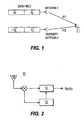
- a block diagram of this system is illustrated in Figure 1. The receiver in such a system has a high complexity due to the use of two joint detectors resulting in higher receiver expense.
- the present invention is a method and system for receiving data transmitted using block space time transmit diversity (BSTTD) in a code division multiple access (CDMA) communication system.
- the system comprises a transmitter for transmitting a first data field using a first antenna and a second data field using a second antenna and a receiver.
- the receiver includes an antenna for receiving the first and second transmitted data fields, and a BSTTD joint detector which determines symbols of the first and second transmitted data fields using a minimum mean square error block linear equalizer model and an approximated Cholesky decomposition of the model.
- Figure 1 is a block diagram of a prior art communication system employing space-time transmit diversity.
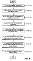
- FIG. 2 is a block diagram of a receiver in accordance with the preferred embodiment of the present invention.
- FIG. 3 is an illustration of matrix structures for approximation of Block Space Time Transmit Diversity (BSTTD) in accordance with the preferred embodiment.
- BSTTD Block Space Time Transmit Diversity
- Figure 4 is a flow diagram of the block space time transmit diversity joint detection method in accordance with the preferred embodiment.
- FIG. 2 is a block diagram of a receiver 10, preferably located at a user equipment (UE), in a CDMA communication system in accordance with the preferred embodiment of the present invention.
- the receiver 10 may be located at the base station and operating on uplink communications.
- the receiver 10 comprises a BSTTD joint detection device (BSTTD JD) 12, a channel estimation device 13 and an antenna 16.
- BSTTD JD BSTTD joint detection device
- the antenna 16 of the UE receives various RF signals including a first and second communication burst from a transmitter.
- the first and second communication bursts comprise the first and second data fields, respectively as described above.
- the first data field includes the first portion D1 and the second portion D2; the second data field includes the negative conjugate of D2, -D2* and the conjugate of D1, D1*.
- a typical communication burst has the two portions of the data fields separated by a midamble. The burst also has a guard period at the end of it to allow for different times of arrival between bursts.
- Each data field of one communication burst is encoded as the first data field, D1, D2.
- Each data field of the other communication burst is encoded as the second data field, - D2*, D1*.
- the respective data fields are spread and a midamble included to produce the first and second communication bursts, respectively.
- Each of the communication bursts are transmitted by a respective first and second antenna in a RF signal to the receiver 10.
- the received RF communication signal including the first and second communication bursts is demodulated and forwarded to the channel estimation device 13 and BSTTD JD 12.
- the channel estimation device 13 processes the demodulated signal and forwards the channel information to the BSTTD JD 12.
- the BSTTD JD 12 receives the demodulated signal including the first and second communication bursts and the channel information from the channel estimation device 13. Using the channel information and the spreading codes of the transmitter, the BSTTD JD 12 estimates the data symbols of the first and second data fields of each communication burst, D1, D2, -D2*, -D1 and combines D1, D2, -D2*,-D1 to recover the original data field D.
- the BSTTD JD 12 estimates the data symbols of each of the received data fields utilizing a simplified minimum mean square error block linear equalizer (MMSE-BLE) based detector.
- MMSE-BLE minimum mean square error block linear equalizer
- the BSTTD JD 12 of the present invention operates in accordance with the following.
- a and B are block banded versions of the propagation matrices of channel 1, associated with antenna 1, and channel 2, associated with antenna 2, respectively. They are rewritten as a 2x2 block matrix as follows.
- Equation 1 the received signal model for block space time transmit diversity is expressed as Equation 1.
- Equations 3 and 4 the data blocks can be represented by Equations 3 and 4 below.
- Equation 5 The MMSE-BLE output is represented as Equation 5. E is shown in Equation 1. ⁇ 2 is the mean noise variance and I is the identity matrix.
- D 11 , D 22 and D 21 are per Equations 7, 8 and 9, respectively.
- D 11 A 11 H A 11 + ( B 22 H B 22 ) * + ⁇ 2 I
- D 22 B 11 H B 11 +( A 22 H A 22 ) * + ⁇ 2 I
- D 21 ( A 22 H B 22 )* -B 11 H A 11 .
- G 11 G 11 H D 11 G 21
- G 11 H D 21
- G 22 H D 22 - G 21
- the estimated symbol sequence can be obtained by solving the following triangular systems per Equations 14, 15, 16 and 17.
- G 11 m 1 d wmf1
- G 22 m 2 d wmf2 * - G 21 m 1
- G 22 H d mmse 2 * m 2
- G 11 H d mmse 1 m 1 - G 21 H d mmse 2 *
- a 22 and B 22 can be represented by the block matrix forms with A 11 and B 11 as follows. Equations 18, 19 and 20 are relationships between A 11 , A 22 , B 11 and B 22 .
- a H / 22, A H / 22, B H / 22 B H / 22 and A H / 22, B H / 22 are the block Toeplitz matrices, but A H / 11A 11 , B H / 11, B 11 and A H / 11B 11 are not because of the lower right sub-blocks in the last terms of the Equations 18, 19 and 20.
- Equation 4 by substituting Equation 18, becomes Equation 21.
- Equation 21 is block Hermitian.
- the solution of the Equation 7 can be approximated by the repeated version of Cholesky decomposition by ignoring the last term, i.e., Equation 22.
- D 11 A H 22 A 22 + ( B H 22 B 22 ) * + ⁇ 2 I Equation 22 is the block Toeplitz matrix approximation. Its complexity is equivalent to the approximated decomposition in the single antenna case.
- Those skilled in the art will recognize that the above equations result in an approximation of G 11 , reducing the complexity of the BSTTD JD 12.
- Equation 24 Further reduction in the complexity of the B STTD JD 12 can be found in the approximation of G 22 .
- Equation 13 becomes Equation 24.
- G 22 G 22 H D 22 - D 21 D 11 -1 D 21 H
- Equation 24 With the assumption that norm(D 22 ) >> norm ( D 21 D 11 -1 D 21 H ) , Equation 24 becomes Equation 25.
- G 22 G 22 H ⁇ D 22 Moreover, from the Equations 8, 19 and 22, Equation 26 results.
- Equations 15 and 17 The major complexity of BSTTD over single antenna is associated with matrix G 21 the Equations 12, 15 and 17.
- the number of complex operations in Equations 15 and 17 is the same as the nonzero elements of G 21 .
- Equation 28 results.
- G 21 G 11 H D 21 D and 22 is per Equation 29.
- D 21 ( A H 22 B 22 ) * - B H 22 A 22
- Equation 29 results in a block Toeplitz matrix. Its general solution, though, is too complex to be readily implemented due to it's multiple forward triangular system solutions. However, it can be simplified using the following properties:
- the simplified G and 21 can be represented by:
- the block matrix representations of the correlation matrix D and 21 and lower triangular matrix G and 21 are written as Equations 30 and 31.
- d 11 equals- d T / 11:
- d ij and f ij per property 1 and approximation 2 have the following structure.
- the first K d element at the last column vector is obtained by the division of the complex number to the real number as per Equation 34.
- Equation 35 The last row vector of matrix A 13 obtained by one forward substitution of size K a , which is represented by Equation 35.
- Equation 33 contains matrix multiplications.
- Each matrix multiplication can be considered as K d +(K d +1) 2 complex multipliers due to the zero elements.
- the preferred embodiment is described in conjunction with the flow chart of Figure 3.
- the received signal is modelled by ignoring the interference between data blocks, such as per Equation 2 (Step 401).
- the received vector is whitening matched filtered, such as per Equations 3 and 4 (Step 402).
- a Cholesky factor of the form of Equation 10 is determined for a MMSE BLE solution (Step 403).
- a sub-matrix of G, G 11 is then calculated by calculating a Cholesky factor of a sub-matrix of D, D 11 (of Equation 7), as per Equation 22 (Step 404).
- Step 405 Another approximation of a sub-matrix of G, G 22 , using the complex conjugate of G 11 , G 11 *, per Equation 26 is calculated (Step 405).
- Another sub-matrix of G, G21 is approximated as being an upper and lower block banded matrix using Equations 31 and 32 (Step 406).
- the symbols of the two data fields, d andmmse 1 and d ⁇ mmse 2 are solved using forward and backward substitution per Equations 35, 36, 37 and 38 (Step 407).
- the original transmitted data is then determined by decoding d andmmse 1 and d andmmse 2 using decoder 15 (Step 408).
Landscapes
- Engineering & Computer Science (AREA)
- Computer Networks & Wireless Communication (AREA)
- Signal Processing (AREA)
- Radio Transmission System (AREA)
Abstract
The receiver is simplified by the use of block banded propagation matrices.
Description
- The present invention relates to communication systems imploring code division multiple access (CDMA) techniques. More particularly, the present invention relates to a transmission diversity scheme which can be applied to a CDMA communication.
- Spatial diversity has been proposed for support of very high data rate users within third generation wide band code division multiple access systems. Using multiple antennas, the systems achieves better gains and link quality, which results in increased system capacity. Classically, diversity has been exploited through the use of either beam steering or through diversity combining.
- More recently, it has been realized that coordinated use of diversity can be achieved through the use of space-time codes. Such systems can theoretically increase capacity by up to a factor equaling the number of transmit and receive antennas in the array. Space-time codes operate on a block of input symbols producing a matrix output over antennas and time.
- In the past, space-time transmit diversity systems have transmitted consecutive symbols simultaneously with their complex conjugates. This type of system, though, may result in symbol overlap at the receiving end. The amount of overlap is dependent on the length of the impulse response of the propagation channel. In time division duplex (TDD) mode, this symbol overlap will have to be accounted for in the joint detection receiver. The joint detector will have to estimate the overlapping transmitted symbols and their conjugates, resulting in an increase in complexity of the joint detection.
- In order to alleviate this increase in joint detection complexity, systems have been created which transmit two similar but different data fields. The first data field, having a first portion, D1, and a second portion, D2, is transmitted by the first antenna. A second data field is produced by modifying the first data field. The negation of the conjugate of D2, -D2*, is the first portion of the second data field and the conjugate of D1, D1*, is the second portion. The second data field is simultaneously transmitted by the second antenna.
- Although this diversity transmission scheme reduces receiver complexity, receivers for this scheme are still very complex. Such receivers utilize two joint detection devices. Each joint detection device recovers the data field transmitted from one of the antennas individually. Such an implementation deals with cross interference between the two transmitted data fields by dealing with each antenna's transmission separately. As a result, each joint detection device treats the other antenna's transmission as noise. The symbols recovered from each joint detection device are combined using a decoder to determine
d 1 andd 2. A block diagram of this system is illustrated in Figure 1. The receiver in such a system has a high complexity due to the use of two joint detectors resulting in higher receiver expense. - Accordingly, there exists a need for alternate receiver implementations.
- The present invention is a method and system for receiving data transmitted using block space time transmit diversity (BSTTD) in a code division multiple access (CDMA) communication system. The system comprises a transmitter for transmitting a first data field using a first antenna and a second data field using a second antenna and a receiver. The receiver includes an antenna for receiving the first and second transmitted data fields, and a BSTTD joint detector which determines symbols of the first and second transmitted data fields using a minimum mean square error block linear equalizer model and an approximated Cholesky decomposition of the model.
- Figure 1 is a block diagram of a prior art communication system employing space-time transmit diversity.
- Figure 2 is a block diagram of a receiver in accordance with the preferred embodiment of the present invention.
- Figure 3 is an illustration of matrix structures for approximation of Block Space Time Transmit Diversity (BSTTD) in accordance with the preferred embodiment.
- Figure 4 is a flow diagram of the block space time transmit diversity joint detection method in accordance with the preferred embodiment.
- Figure 2 is a block diagram of a receiver 10, preferably located at a user equipment (UE), in a CDMA communication system in accordance with the preferred embodiment of the present invention. Although it is preferable to have the receiver located at the UE, the receiver 10 may be located at the base station and operating on uplink communications. The receiver 10 comprises a BSTTD joint detection device (BSTTD JD) 12, a channel estimation device 13 and an antenna 16. The antenna 16 of the UE receives various RF signals including a first and second communication burst from a transmitter.
- The first and second communication bursts comprise the first and second data fields, respectively as described above. The first data field includes the first portion D1 and the second portion D2; the second data field includes the negative conjugate of D2, -D2* and the conjugate of D1, D1*. A typical communication burst has the two portions of the data fields separated by a midamble. The burst also has a guard period at the end of it to allow for different times of arrival between bursts. Each data field of one communication burst is encoded as the first data field, D1, D2. Each data field of the other communication burst is encoded as the second data field, - D2*, D1*. The respective data fields are spread and a midamble included to produce the first and second communication bursts, respectively. Each of the communication bursts are transmitted by a respective first and second antenna in a RF signal to the receiver 10.
- The received RF communication signal including the first and second communication bursts is demodulated and forwarded to the channel estimation device 13 and BSTTD JD 12. The channel estimation device 13 processes the demodulated signal and forwards the channel information to the BSTTD JD 12.
- The BSTTD JD 12 receives the demodulated signal including the first and second communication bursts and the channel information from the channel estimation device 13. Using the channel information and the spreading codes of the transmitter, the BSTTD JD 12 estimates the data symbols of the first and second data fields of each communication burst, D1, D2, -D2*, -D1 and combines D1, D2, -D2*,-D1 to recover the original data field D.
- In accordance with the preferred embodiment of the present invention, the BSTTD JD 12 estimates the data symbols of each of the received data fields utilizing a simplified minimum mean square error block linear equalizer (MMSE-BLE) based detector. The BSTTD JD 12 of the present invention operates in accordance with the following. A and B are block banded versions of the propagation matrices of channel 1, associated with antenna 1, and channel 2, associated with antenna 2, respectively. They are rewritten as a 2x2 block matrix as follows.

- Accordingly, the received signal model for block space time transmit diversity is expressed as Equation 1.
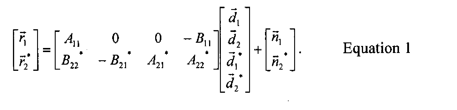
- Since the length of the blocks is much longer than the channel delay spread, the interference between adjacent blocks, A21 and B21, can be ignored, and the received signal model can be simplified to Equation 2:

- In order to estimate the data blocks a MMSE BLE algorithm for BSTTD may be used. Using whitening matched filtering, the data blocks can be represented by Equations 3 and 4 below.


- The MMSE-BLE output is represented as Equation 5.E is shown in Equation 1. σ2 is the mean noise variance and I is the identity matrix.

- In the single antenna BLE, the major complexity for block STTD is due to the matrix inversion, which is preferably implemented with an approximate Cholesky decomposition. The block matrix representation of the correlation matrix for Cholesky decomposition is written as Equation 6.D11, D22 and D21 are per Equations 7, 8 and 9, respectively.

- The lower triangular matrix for the Cholesky decomposition D = GGH is written as Equation 10.Equations 11, 12 and 13 are relationships between G11, G21, G22, D11, D21 and D22.

- The estimated symbol sequence can be obtained by solving the following triangular systems per Equations 14, 15, 16 and 17.
- In a single antenna system, one Cholesky decomposition is required. The use of a diversity antenna increases the complexity of the decoding of the symbols by requiring two Cholesky decompositions (Equations 11 and 13) and one forward substitution (Equation 12). This increases the complexity of a BSTTD system over a single antenna system by more than two times. Moreover, the B STTD decoder of this system does not cancel the interference of the first sub-block to the second sub-block, which results in more error in the detection.
- The following describes reducing the complexity further. From the structure of the transmission matrix, A22 and B22 can be represented by the block matrix forms with A11 and B11 as follows.Equations 18, 19 and 20 are relationships between A11, A22, B11 and B22.



- Those skilled in the art will realize that A H / 22, A H / 22, B H / 22 B H / 22 and A H / 22, B H / 22are the block Toeplitz matrices, but A H / 11A11, B H / 11, B11 and A H / 11B11 are not because of the lower right sub-blocks in the last terms of the Equations 18, 19 and 20.
- Equation 4 , by substituting Equation 18, becomes Equation 21.Equation 21 is block Hermitian. The solution of the Equation 7 can be approximated by the repeated version of Cholesky decomposition by ignoring the last term, i.e., Equation 22.

- Further reduction in the complexity of the B STTD JD 12 can be found in the approximation of G22. From Equations 11 and 12, Equation 13 becomes Equation 24.

- Similar to the approximation of G11 above, the above solution can be approximated to the repeated version of Cholesky's decomposition by ignoring the last term, which results in Equation 27.
- By this approximation, G22 and, hence, D22 (Equations 8 and 13) do not need to be computed explicitly. Therefore, the complexity of Cholesky decomposition with BSTTD becomes the same as the single antenna system.
- The major complexity of BSTTD over single antenna is associated with matrix G21 the Equations 12, 15 and 17. The number of complex operations in Equations 15 and 17 is the same as the nonzero elements of G21. The less nonzero elements, reduces the complexity of Equations 15 and 17. One approach to reduce complexity is to assume G and21 = 0. However, this approximation introduces an error into the solution, which is typically not desired.
- Therefore, another approach to reduce complexity is to approximate G and 21 in accordance with the following. From Equations 9 and 12, Equation 28 results.
- Equation 29 results in a block Toeplitz matrix. Its general solution, though, is too complex to be readily implemented due to it's multiple forward triangular system solutions. However, it can be simplified using the following properties:
- Property 1: The matrix D and 21, is skew-symmetric block Toeplitz, i.e., D and21 =-D and 21 T . The diagonal terms of D and 21 are always zeros.
- Property 2: All the entries of D and 21 are zeros except the elements in the last column or in the last row of the sub-block matrix. (See Fig.2 (a))
- Property 3: The matrix G and 21 has a block Toeplitz structure.
- Property 4: The matrix G and 21 is lower block banded with its bandwidth equal to (L·Ka -1). (See Fig.2 (b)). L is the number of the non-zero blocks at the first row or column block. It is equivalent to the length of intersymbol interference plus one, i.e., L = Lisi + 1, where Lisi = ceil(W/SF), W is the channel length and ceil(x) denotes the smallest integer larger than x. Ka is the total number of active codes (physical channel), e.g., Ka = K + 1 with K DCH in BCH timeslot.
-
- The complexity will be dramatically reduced using the above properties and the approximation to the block banded matrix with the same sub-block structure as in property 2 for D and 21. This approximated structure is shown in Fig.3 (c). Fig.3 (d) shows the exact G and 21 with different collar scale from Fig. 3 (b). The computation of G and 21 will be simplified by the above properties as well as the following approximations:
- Approximation 1: G and 21 is upper and lower block banded matrix with its bandwidth (L·K a -1).
- Approximation 2: G and 21, has the same structure as D and 21.
-
- With approximation 1, the simplified G and 21 can be represented by:The block matrix representations of the correlation matrix D and21 and lower triangular matrix G and21 are written as Equations 30 and 31.

 d 11 equals- d T / 11: dij and fij per property 1 and approximation 2 have the following structure.
 The solution of
 A = [aij ] Ka / i,j=1 and D = [dij ] Ka / i,j=1 with the above matrix structure and the lower triangular matrix G = [gij ] Ka / i,j=1 satisfies the matrix equation AGH = D. Kd is the number of dedicated channels (DCH) and Ka = Kd +1 is the total number of physical channels in the broadcast channel (BCH) time slot. The first K d element at the last column vector is obtained by the division of the complex number to the real number as per Equation 34.
- The last row vector of matrix A 13 obtained by one forward substitution of size Ka , which is represented by Equation 35.

- In addition, the right hand side of Equation 33 contains matrix multiplications. Each matrix multiplication can be considered as Kd+(Kd +1)2 complex multipliers due to the zero elements.
- The BSTTD algorithm is simplified using the above approximation as follows:
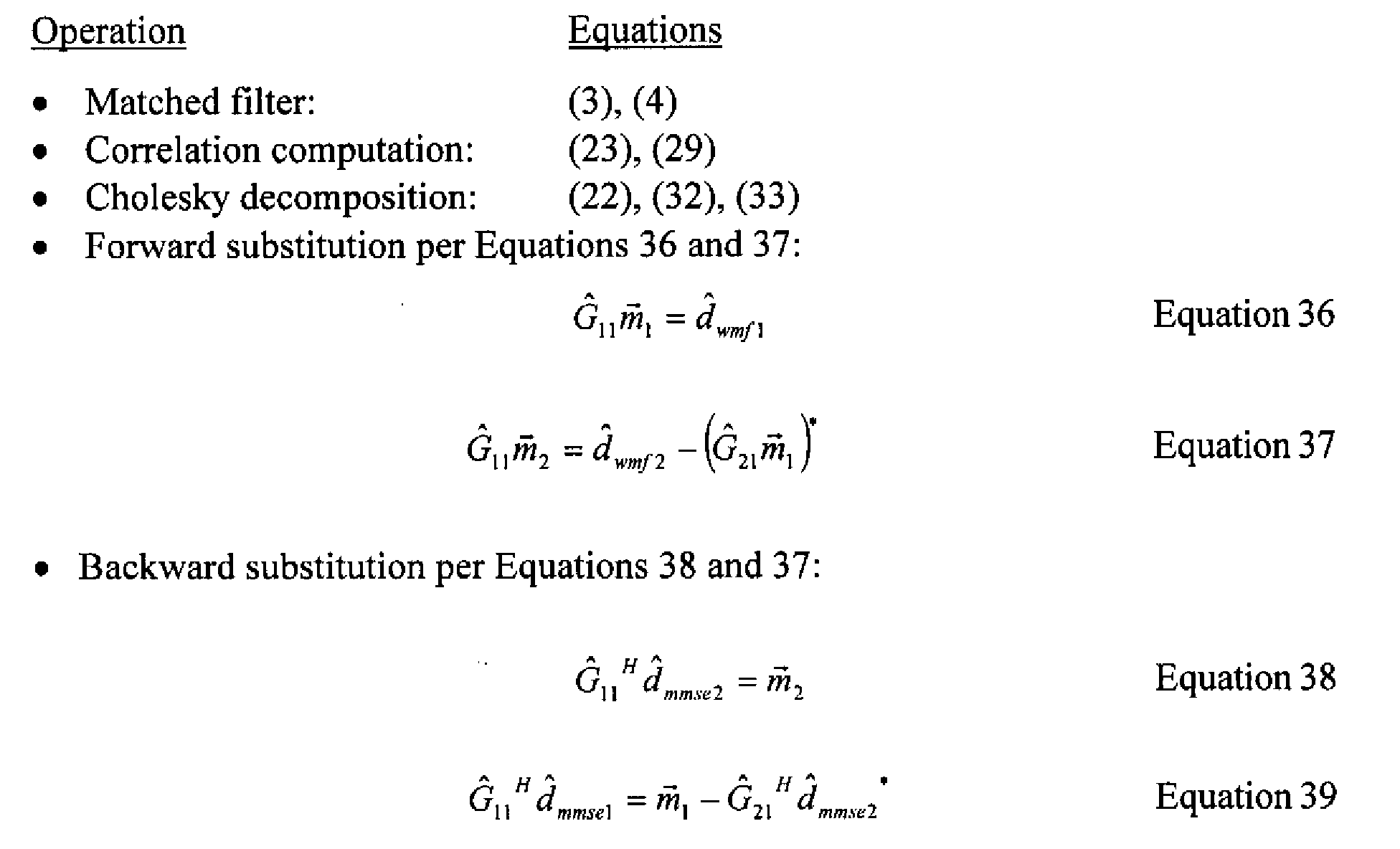
- The preferred embodiment is described in conjunction with the flow chart of Figure 3. The received signal is modelled by ignoring the interference between data blocks, such as per Equation 2 (Step 401). The received vector is whitening matched filtered, such as per Equations 3 and 4 (Step 402). A Cholesky factor of the form of Equation 10 is determined for a MMSE BLE solution (Step 403). A sub-matrix of G, G11, is then calculated by calculating a Cholesky factor of a sub-matrix of D, D11 (of Equation 7), as per Equation 22 (Step 404). Another approximation of a sub-matrix of G, G22, using the complex conjugate of G11, G11*, per Equation 26 is calculated (Step 405). Another sub-matrix of G, G21 is approximated as being an upper and lower block banded matrix using Equations 31 and 32 (Step 406). The symbols of the two data fields, d andmmse 1 and d ˙mmse 2 are solved using forward and backward substitution per Equations 35, 36, 37 and 38 (Step 407). The original transmitted data is then determined by decoding d andmmse 1 and d andmmse 2 using decoder 15 (Step 408).
- While the present invention has been described in terms of the preferred embodiment, other variations which are within the scope of the invention as outlined in the claims below will be apparent to those skilled in the art.
-
- 1. A method for receiving data transmitted using block space time transmit
diversity (BSTTD), a BSTTD transmitter transmits a first data field using a first
antenna and a second data field using a second antenna, the second data field produced
by rearranging blocks of the first data field, the method comprising:
- receiving a received vector comprising both the first and second transmitted data fields;
- whitening matched filtering the received vector;
- utilizing a minimum mean square error block linear equalizer model to determine symbols of the first and second data fields, the model ignoring interference between data blocks; and
- determining symbols of the first and second transmitted data fields using an approximate Cholesky decomposition of the model, forward and backward substitution.
- 2. The method of claim 1 wherein the first and second data fields transmitted symbols are decoded to estimate data of the first data field.
- 3. The method of claim 1 wherein a Cholesky factor used in the approximate Cholesky decomposition includes four block matrices, a first block of the four block matrices is approximated as a complex conjugate of a second block of the four block matrices.
- 4. The method of claim 3 wherein a third block of the four block matrices is approximated as being an upper and lower block banded matrix.
- 5. The method of claim 4 wherein the third block of the four block matrices comprises all zero elements.
- 6. A receiver for receiving data transmitted using block space time transmit
diversity (BSTTD) from a BSTTD transmitter which transmits a first data field using a
first antenna and a second data field using a second antenna, the second data field
using a second antenna, the second data field produced by rearranging blocks of the
first data field, the receiver comprising:
- an antenna for receiving a vector comprising both the first and second transmitted data fields;
- a BSTTD joint detector which utilizes a minimum mean square error block linear equalizer model, an approximate Cholesky decomposition ofthe model, forward and backward substitution to determine symbols of the first and second transmitted data fields; and
- said model ignoring interference between data blocks.
- 7. The receiver of claim 6 wherein said joint detector decodes the symbols of the first and second transmitted data fields to estimate data of the first data field.
- 8. The receiver of claim 6 wherein a Cholesky factor used in the approximate Cholesky decomposition includes four block matrices, a first block of the four block matrices is approximated as a complex conjugate of a second block of the four block matrices.
- 9. The receiver of claim 8 wherein a third block of the four block matrices is approximated as being an upper and lower block banded matrix.
- 10. The receiver of claim 9 wherein the third block of the four block matrices comprises all zero elements.
- 11. A code division multiple access (CDMA) communication system
including:
- a block space time transmit diversity (BSTTD) transmitter, using block space time transmit diversity, for transmitting a first data field using a first antenna and a second data field using a second antenna, the second data field produced by rearranging blocks of the first data field; and
- a receiver, for receiving data transmitted using BSTTD, comprising:
- an antenna for receiving a vector comprising both the first and second transmitted data fields;
- a BSTTD joint detector which utilizes a minimum mean square error block linear equalizer model, an approximate Cholesky decomposition of the model, forward and backward substitution to determine symbols of the first and second transmitted data fields; and
- the model ignoring interference between data blocks.
- 12. The system of claim 11 wherein said joint detector decodes the symbols of the first and second transmitted data fields to estimate data of the first data field.
- 13. The system of claim 11 wherein a Cholesky factor used in the approximate Cholesky decomposition includes four block matrices, a first block of the four block matrices is approximated as a complex conjugate of a second block of the four block matrices.
- 14. The system of claim 13 wherein a third block of the four block matrices is approximated as being an upper and lower block banded matrix.
- 15. The system of claim 14 wherein the third block of the four block matrices comprises all zero elements.
-
Claims (9)
- A method for receiving data fields transmitted using block space time transmit diversity (BSTTD) in a code division multiple access (CDMA) communication system, the method comprising the steps of:transmitting a first data field (
d 1d 2 ) using a first antenna, and a second data field (-d * 2d * 1 ) using a second antenna, wherein * denotes a conjugate;receiving the first data field and the second data field;generating a received signal model ignoring interference between the data blocks according to:wherein A and B are block banded versions of the propagation matrices associated with the first and the second antenna, respectively; and, determining transmitted data symbols of the first data field and the second data field utilizing minimum mean square error block linear equalization, approximate Cholesky decomposition, and forward and backward substitution.
 - The method of claim 1 wherein the received data fields are processed by a whitening matched filter.
- The method of claim 2 wherein the received data fields are processed by a channel estimator generating channel information to be used in determining transmitted data symbols.
- A receiver for recovering data fields transmitted from a block space time transmit diversity (BSTTD) transmitter which transmits a first data field (
d 1d 2) using a first antenna and a second data field (-d * 2d 1*) using a second antenna, the second data field produced by rearranging blocks of the first data field, the receiver comprising:wherein A and B are block banded versions of the propagation matrices associated with the first and the second antenna, respectively.an antenna for receiving a vector comprising both the first data field and the second data field; and,a BSTTD joint detector for determining transmitted symbols of the first data field and the second data field utilizing minimum mean square error block linear equalization, approximate Cholesky decomposition, and forward and backward substitution, using a received signal model ignoring interference between the data blocks according to:
- The receiver of claim 5 further comprising a whitening matched filter to process the received data fields.
- The receiver of claim 6 further comprising a channel estimator to generate channel information.
- A CDMA communication system for recovering data fields transmitted using block space time transmit diversity (BSTTD), the system comprising:wherein A and B are block banded versions of the propagation matrices associated with the first and the second antenna, respectively.a transmitter transmitting a first data field (
d 1d 2 ) using a first antenna and a second data field (-d * / 2d * / 1) using a second antenna; anda receiver for receiving data fields transmitted using BSTTD comprising:an antenna for receiving a vector comprising the first data field and the second data field; and,a BSTTD joint detector which utilizes minimum mean square error block linear equalization, approximate Cholesky decomposition, and forward and backward substitution to determine symbols of the first data field and the second data field, using a received signal model ignoring interference between the data blocks according to: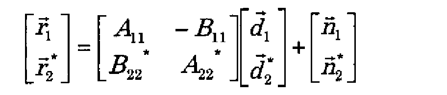
- The system of claim 9 further comprising a whitening matched filter to process the received data fields.
- The system of claim 10 further comprising a channel estimator to generate channel information.
Applications Claiming Priority (5)
| Application Number | Priority Date | Filing Date | Title |
|---|---|---|---|
| US26391501P | 2001-01-25 | 2001-01-25 | |
| US263915P | 2001-01-25 | ||
| US34793 | 2001-12-27 | ||
| US10/034,793 US6707864B2 (en) | 2001-01-25 | 2001-12-27 | Simplified block linear equalizer with block space time transmit diversity |
| EP02714751A EP1354424A2 (en) | 2001-01-25 | 2002-01-18 | Simplified block linear equalizer with block space time transmit diversity |
Related Parent Applications (1)
| Application Number | Title | Priority Date | Filing Date |
|---|---|---|---|
| EP02714751A Division EP1354424A2 (en) | 2001-01-25 | 2002-01-18 | Simplified block linear equalizer with block space time transmit diversity |
Publications (3)
| Publication Number | Publication Date |
|---|---|
| EP1560347A1 true EP1560347A1 (en) | 2005-08-03 |
| EP1560347B1 EP1560347B1 (en) | 2007-04-25 |
| EP1560347B8 EP1560347B8 (en) | 2007-09-19 |
Family
ID=34657530
Family Applications (1)
| Application Number | Title | Priority Date | Filing Date |
|---|---|---|---|
| EP05100393A Expired - Lifetime EP1560347B8 (en) | 2001-01-25 | 2002-01-18 | Simplified block linear equalizer with block space time transmit diversity |
Country Status (1)
| Country | Link |
|---|---|
| EP (1) | EP1560347B8 (en) |
Cited By (1)
| Publication number | Priority date | Publication date | Assignee | Title |
|---|---|---|---|---|
| EP1912367A1 (en) * | 2006-10-11 | 2008-04-16 | Thomson Licensing | Method of decoding of a received multidimensional signal and corresponding device |
Citations (1)
| Publication number | Priority date | Publication date | Assignee | Title |
|---|---|---|---|---|
| EP1069707A1 (en) * | 1999-07-13 | 2001-01-17 | Motorola, Inc. | Transmit diversity transmitter and receiver for radio communications systems |
-
2002
- 2002-01-18 EP EP05100393A patent/EP1560347B8/en not_active Expired - Lifetime
Patent Citations (1)
| Publication number | Priority date | Publication date | Assignee | Title |
|---|---|---|---|---|
| EP1069707A1 (en) * | 1999-07-13 | 2001-01-17 | Motorola, Inc. | Transmit diversity transmitter and receiver for radio communications systems |
Non-Patent Citations (4)
| Title |
|---|
| BENVENUTO N ET AL: "Joint detection with low computational complexity for hybrid TD-CDMA systems", VTC 1999-FALL. IEEE VTS 50TH. VEHICULAR TECHNOLOGY CONFERENCE. GATEWAY TO THE 21ST. CENTURY COMMUNICATIONS VILLAGE. AMSTERDAM, SEPT. 19 - 22, 1999, IEEE VEHICULAR TECHNOLGY CONFERENCE, NEW YORK, NY: IEEE, US, vol. 1 CONF. 50, 19 September 1999 (1999-09-19), pages 618 - 622, XP002149179, ISBN: 0-7803-5436-2 * |
| KARIMI H R ET AL: "A novel and efficient solution to block-based joint-detection using approximate Cholesky factorization", PERSONAL, INDOOR AND MOBILE RADIO COMMUNICATIONS, 1998. THE NINTH IEEE INTERNATIONAL SYMPOSIUM ON BOSTON, MA, USA 8-11 SEPT. 1998, NEW YORK, NY, USA,IEEE, US, 8 September 1998 (1998-09-08), pages 1340 - 1345, XP010314638, ISBN: 0-7803-4872-9 * |
| KARIMI H R: "Efficient multi-rate multi-user detection for the asynchronous WCDMA uplink", VTC 1999-FALL. IEEE VTS 50TH. VEHICULAR TECHNOLOGY CONFERENCE. GATEWAY TO THE 21ST. CENTURY COMMUNICATIONS VILLAGE. AMSTERDAM, SEPT. 19 - 22, 1999, IEEE VEHICULAR TECHNOLGY CONFERENCE, NEW YORK, NY: IEEE, US, vol. 1 CONF. 50, 19 September 1999 (1999-09-19), pages 593 - 597, XP002142538, ISBN: 0-7803-5436-2 * |
| KLEIN A ET AL: "ZERO FORCING AND MINIMUM MEAN-SQUARE-ERROR EQUALIZATION FOR MULTIUSER DETECTION IN CODE-DIVISION MULTIPLE-ACCESS CHANNELS", IEEE TRANSACTIONS ON VEHICULAR TECHNOLOGY, IEEE INC. NEW YORK, US, vol. 45, no. 2, 1 May 1996 (1996-05-01), pages 276 - 287, XP000598095, ISSN: 0018-9545 * |
Cited By (1)
| Publication number | Priority date | Publication date | Assignee | Title |
|---|---|---|---|---|
| EP1912367A1 (en) * | 2006-10-11 | 2008-04-16 | Thomson Licensing | Method of decoding of a received multidimensional signal and corresponding device |
Also Published As
| Publication number | Publication date |
|---|---|
| EP1560347B1 (en) | 2007-04-25 |
| EP1560347B8 (en) | 2007-09-19 |
Similar Documents
| Publication | Publication Date | Title |
|---|---|---|
| US6707864B2 (en) | Simplified block linear equalizer with block space time transmit diversity | |
| US20070121747A1 (en) | Method and apparatus for transferring signals in a wireless communication system | |
| JP4359388B2 (en) | Method and apparatus for joint detection of data in a direct sequence spread spectrum communication system | |
| EP1340334B1 (en) | Simple block space time transmit diversity using multiple spreading codes | |
| JP2008172814A (en) | Modified block space-time transmit diversity encoder | |
| CN1360765A (en) | Transmit diversity transmitter and receiver for radio communications systems | |
| EP1560347B1 (en) | Simplified block linear equalizer with block space time transmit diversity | |
| CN100446434C (en) | Method for receiving data, its receiver and wireless communication system | |
| EP1650892A1 (en) | Modified block space time transmit diversity decoder | |
| AU2006201932A1 (en) | Efficient Multiple Input Multiple Output System for Multi-Path Fading Channels |
Legal Events
| Date | Code | Title | Description |
|---|---|---|---|
| PUAI | Public reference made under article 153(3) epc to a published international application that has entered the european phase |
Free format text: ORIGINAL CODE: 0009012 |
|
| 17P | Request for examination filed |
Effective date: 20050121 |
|
| AC | Divisional application: reference to earlier application |
Ref document number: 1354424 Country of ref document: EP Kind code of ref document: P |
|
| AK | Designated contracting states |
Kind code of ref document: A1 Designated state(s): AT BE CH CY DE DK ES FI FR GB GR IE IT LI LU MC NL PT SE TR |
|
| AKX | Designation fees paid |
Designated state(s): AT BE CH CY DE DK ES FI FR GB GR IE IT LI LU MC NL PT SE TR |
|
| GRAP | Despatch of communication of intention to grant a patent |
Free format text: ORIGINAL CODE: EPIDOSNIGR1 |
|
| GRAS | Grant fee paid |
Free format text: ORIGINAL CODE: EPIDOSNIGR3 |
|
| GRAA | (expected) grant |
Free format text: ORIGINAL CODE: 0009210 |
|
| AC | Divisional application: reference to earlier application |
Ref document number: 1354424 Country of ref document: EP Kind code of ref document: P |
|
| AK | Designated contracting states |
Kind code of ref document: B1 Designated state(s): AT BE CH CY DE DK ES FI FR GB GR IE IT LI LU MC NL PT SE TR |
|
| PG25 | Lapsed in a contracting state [announced via postgrant information from national office to epo] |
Ref country code: LI Free format text: LAPSE BECAUSE OF FAILURE TO SUBMIT A TRANSLATION OF THE DESCRIPTION OR TO PAY THE FEE WITHIN THE PRESCRIBED TIME-LIMIT Effective date: 20070425 Ref country code: CH Free format text: LAPSE BECAUSE OF FAILURE TO SUBMIT A TRANSLATION OF THE DESCRIPTION OR TO PAY THE FEE WITHIN THE PRESCRIBED TIME-LIMIT Effective date: 20070425 |
|
| REG | Reference to a national code |
Ref country code: GB Ref legal event code: FG4D |
|
| RAP2 | Party data changed (patent owner data changed or rights of a patent transferred) |
Owner name: INTERDIGITAL PATENT CORPORATION |
|
| RAP2 | Party data changed (patent owner data changed or rights of a patent transferred) |
Owner name: INTERDIGITAL TECHNOLOGY CORPORATION |
|
| REG | Reference to a national code |
Ref country code: SE Ref legal event code: TRGR |
|
| REG | Reference to a national code |
Ref country code: IE Ref legal event code: FG4D |
|
| REG | Reference to a national code |
Ref country code: CH Ref legal event code: EP |
|
| REF | Corresponds to: |
Ref document number: 60219834 Country of ref document: DE Date of ref document: 20070606 Kind code of ref document: P |
|
| REG | Reference to a national code |
Ref country code: GB Ref legal event code: ERR Free format text: NOTIFICATION HAS NOW BEEN RECEIVED FROM THE EUROPEAN PATENT OFFICE THAT THE CORRECT NAME IS: INTERDIGITAL TECHNOLOGY CORPORATION THIS CORRECTION WAS PUBLISHED IN THE EUROPEAN PATENT BULLETIN 07/19 DATED 20070509 |
|
| NLT2 | Nl: modifications (of names), taken from the european patent patent bulletin |
Owner name: INTERDIGITAL TECHNOLOGY CORPORATION Effective date: 20070509 Owner name: INTERDIGITAL PATENT CORPORATION Effective date: 20070502 |
|
| ET | Fr: translation filed | ||
| PG25 | Lapsed in a contracting state [announced via postgrant information from national office to epo] |
Ref country code: PT Free format text: LAPSE BECAUSE OF FAILURE TO SUBMIT A TRANSLATION OF THE DESCRIPTION OR TO PAY THE FEE WITHIN THE PRESCRIBED TIME-LIMIT Effective date: 20070925 |
|
| REG | Reference to a national code |
Ref country code: CH Ref legal event code: PL |
|
| NLV1 | Nl: lapsed or annulled due to failure to fulfill the requirements of art. 29p and 29m of the patents act | ||
| REG | Reference to a national code |
Ref country code: ES Ref legal event code: FG2A Ref document number: 2284122 Country of ref document: ES Kind code of ref document: T3 |
|
| PG25 | Lapsed in a contracting state [announced via postgrant information from national office to epo] |
Ref country code: AT Free format text: LAPSE BECAUSE OF FAILURE TO SUBMIT A TRANSLATION OF THE DESCRIPTION OR TO PAY THE FEE WITHIN THE PRESCRIBED TIME-LIMIT Effective date: 20070425 |
|
| PG25 | Lapsed in a contracting state [announced via postgrant information from national office to epo] |
Ref country code: BE Free format text: LAPSE BECAUSE OF FAILURE TO SUBMIT A TRANSLATION OF THE DESCRIPTION OR TO PAY THE FEE WITHIN THE PRESCRIBED TIME-LIMIT Effective date: 20070425 |
|
| PG25 | Lapsed in a contracting state [announced via postgrant information from national office to epo] |
Ref country code: DK Free format text: LAPSE BECAUSE OF FAILURE TO SUBMIT A TRANSLATION OF THE DESCRIPTION OR TO PAY THE FEE WITHIN THE PRESCRIBED TIME-LIMIT Effective date: 20070425 Ref country code: NL Free format text: LAPSE BECAUSE OF FAILURE TO SUBMIT A TRANSLATION OF THE DESCRIPTION OR TO PAY THE FEE WITHIN THE PRESCRIBED TIME-LIMIT Effective date: 20070425 |
|
| PGFP | Annual fee paid to national office [announced via postgrant information from national office to epo] |
Ref country code: MC Payment date: 20071224 Year of fee payment: 7 |
|
| PLBE | No opposition filed within time limit |
Free format text: ORIGINAL CODE: 0009261 |
|
| STAA | Information on the status of an ep patent application or granted ep patent |
Free format text: STATUS: NO OPPOSITION FILED WITHIN TIME LIMIT |
|
| 26N | No opposition filed |
Effective date: 20080128 |
|
| PG25 | Lapsed in a contracting state [announced via postgrant information from national office to epo] |
Ref country code: GR Free format text: LAPSE BECAUSE OF FAILURE TO SUBMIT A TRANSLATION OF THE DESCRIPTION OR TO PAY THE FEE WITHIN THE PRESCRIBED TIME-LIMIT Effective date: 20070726 |
|
| PGFP | Annual fee paid to national office [announced via postgrant information from national office to epo] |
Ref country code: IE Payment date: 20080111 Year of fee payment: 7 Ref country code: LU Payment date: 20080114 Year of fee payment: 7 |
|
| PG25 | Lapsed in a contracting state [announced via postgrant information from national office to epo] |
Ref country code: CY Free format text: LAPSE BECAUSE OF FAILURE TO SUBMIT A TRANSLATION OF THE DESCRIPTION OR TO PAY THE FEE WITHIN THE PRESCRIBED TIME-LIMIT Effective date: 20070425 |
|
| PG25 | Lapsed in a contracting state [announced via postgrant information from national office to epo] |
Ref country code: MC Free format text: LAPSE BECAUSE OF NON-PAYMENT OF DUE FEES Effective date: 20090131 |
|
| PG25 | Lapsed in a contracting state [announced via postgrant information from national office to epo] |
Ref country code: IE Free format text: LAPSE BECAUSE OF NON-PAYMENT OF DUE FEES Effective date: 20090119 |
|
| PG25 | Lapsed in a contracting state [announced via postgrant information from national office to epo] |
Ref country code: TR Free format text: LAPSE BECAUSE OF FAILURE TO SUBMIT A TRANSLATION OF THE DESCRIPTION OR TO PAY THE FEE WITHIN THE PRESCRIBED TIME-LIMIT Effective date: 20070425 |
|
| PG25 | Lapsed in a contracting state [announced via postgrant information from national office to epo] |
Ref country code: LU Free format text: LAPSE BECAUSE OF NON-PAYMENT OF DUE FEES Effective date: 20090118 |
|
| PGFP | Annual fee paid to national office [announced via postgrant information from national office to epo] |
Ref country code: ES Payment date: 20131211 Year of fee payment: 13 |
|
| PGFP | Annual fee paid to national office [announced via postgrant information from national office to epo] |
Ref country code: SE Payment date: 20140113 Year of fee payment: 13 Ref country code: FI Payment date: 20140110 Year of fee payment: 13 Ref country code: DE Payment date: 20140115 Year of fee payment: 13 |
|
| PGFP | Annual fee paid to national office [announced via postgrant information from national office to epo] |
Ref country code: FR Payment date: 20140108 Year of fee payment: 13 Ref country code: IT Payment date: 20140120 Year of fee payment: 13 |
|
| PGFP | Annual fee paid to national office [announced via postgrant information from national office to epo] |
Ref country code: GB Payment date: 20140115 Year of fee payment: 13 |
|
| REG | Reference to a national code |
Ref country code: DE Ref legal event code: R119 Ref document number: 60219834 Country of ref document: DE |
|
| REG | Reference to a national code |
Ref country code: SE Ref legal event code: EUG |
|
| GBPC | Gb: european patent ceased through non-payment of renewal fee |
Effective date: 20150118 |
|
| PG25 | Lapsed in a contracting state [announced via postgrant information from national office to epo] |
Ref country code: GB Free format text: LAPSE BECAUSE OF NON-PAYMENT OF DUE FEES Effective date: 20150118 Ref country code: FI Free format text: LAPSE BECAUSE OF NON-PAYMENT OF DUE FEES Effective date: 20150118 Ref country code: DE Free format text: LAPSE BECAUSE OF NON-PAYMENT OF DUE FEES Effective date: 20150801 |
|
| REG | Reference to a national code |
Ref country code: FR Ref legal event code: ST Effective date: 20150930 |
|
| PG25 | Lapsed in a contracting state [announced via postgrant information from national office to epo] |
Ref country code: FR Free format text: LAPSE BECAUSE OF NON-PAYMENT OF DUE FEES Effective date: 20150202 Ref country code: SE Free format text: LAPSE BECAUSE OF NON-PAYMENT OF DUE FEES Effective date: 20150119 |
|
| PG25 | Lapsed in a contracting state [announced via postgrant information from national office to epo] |
Ref country code: IT Free format text: LAPSE BECAUSE OF NON-PAYMENT OF DUE FEES Effective date: 20150118 |
|
| REG | Reference to a national code |
Ref country code: ES Ref legal event code: FD2A Effective date: 20160226 |
|
| PG25 | Lapsed in a contracting state [announced via postgrant information from national office to epo] |
Ref country code: ES Free format text: LAPSE BECAUSE OF NON-PAYMENT OF DUE FEES Effective date: 20150119 |