EP1559973B1 - Refrigerator and cooling air passage structure thereof - Google Patents
Refrigerator and cooling air passage structure thereof Download PDFInfo
- Publication number
- EP1559973B1 EP1559973B1 EP05290171A EP05290171A EP1559973B1 EP 1559973 B1 EP1559973 B1 EP 1559973B1 EP 05290171 A EP05290171 A EP 05290171A EP 05290171 A EP05290171 A EP 05290171A EP 1559973 B1 EP1559973 B1 EP 1559973B1
- Authority
- EP
- European Patent Office
- Prior art keywords
- cooling air
- freezing
- refrigerator
- chamber
- adiabatic
- Prior art date
- Legal status (The legal status is an assumption and is not a legal conclusion. Google has not performed a legal analysis and makes no representation as to the accuracy of the status listed.)
- Expired - Lifetime
Links
Images




Classifications
-
- A—HUMAN NECESSITIES
- A47—FURNITURE; DOMESTIC ARTICLES OR APPLIANCES; COFFEE MILLS; SPICE MILLS; SUCTION CLEANERS IN GENERAL
- A47D—FURNITURE SPECIALLY ADAPTED FOR CHILDREN
- A47D13/00—Other nursery furniture
- A47D13/08—Devices for use in guiding or supporting children, e.g. safety harness
- A47D13/083—Baby feeding cushions
-
- F—MECHANICAL ENGINEERING; LIGHTING; HEATING; WEAPONS; BLASTING
- F25—REFRIGERATION OR COOLING; COMBINED HEATING AND REFRIGERATION SYSTEMS; HEAT PUMP SYSTEMS; MANUFACTURE OR STORAGE OF ICE; LIQUEFACTION SOLIDIFICATION OF GASES
- F25D—REFRIGERATORS; COLD ROOMS; ICE-BOXES; COOLING OR FREEZING APPARATUS NOT OTHERWISE PROVIDED FOR
- F25D23/00—General constructional features
- F25D23/12—Arrangements of compartments additional to cooling compartments; Combinations of refrigerators with other equipment, e.g. stove
- F25D23/126—Water cooler
-
- F—MECHANICAL ENGINEERING; LIGHTING; HEATING; WEAPONS; BLASTING
- F25—REFRIGERATION OR COOLING; COMBINED HEATING AND REFRIGERATION SYSTEMS; HEAT PUMP SYSTEMS; MANUFACTURE OR STORAGE OF ICE; LIQUEFACTION SOLIDIFICATION OF GASES
- F25D—REFRIGERATORS; COLD ROOMS; ICE-BOXES; COOLING OR FREEZING APPARATUS NOT OTHERWISE PROVIDED FOR
- F25D17/00—Arrangements for circulating cooling fluids; Arrangements for circulating gas, e.g. air, within refrigerated spaces
- F25D17/04—Arrangements for circulating cooling fluids; Arrangements for circulating gas, e.g. air, within refrigerated spaces for circulating air, e.g. by convection
- F25D17/06—Arrangements for circulating cooling fluids; Arrangements for circulating gas, e.g. air, within refrigerated spaces for circulating air, e.g. by convection by forced circulation
- F25D17/062—Arrangements for circulating cooling fluids; Arrangements for circulating gas, e.g. air, within refrigerated spaces for circulating air, e.g. by convection by forced circulation in household refrigerators
- F25D17/065—Arrangements for circulating cooling fluids; Arrangements for circulating gas, e.g. air, within refrigerated spaces for circulating air, e.g. by convection by forced circulation in household refrigerators with compartments at different temperatures
-
- F—MECHANICAL ENGINEERING; LIGHTING; HEATING; WEAPONS; BLASTING
- F25—REFRIGERATION OR COOLING; COMBINED HEATING AND REFRIGERATION SYSTEMS; HEAT PUMP SYSTEMS; MANUFACTURE OR STORAGE OF ICE; LIQUEFACTION SOLIDIFICATION OF GASES
- F25C—PRODUCING, WORKING OR HANDLING ICE
- F25C1/00—Producing ice
- F25C1/04—Producing ice by using stationary moulds
-
- F—MECHANICAL ENGINEERING; LIGHTING; HEATING; WEAPONS; BLASTING
- F25—REFRIGERATION OR COOLING; COMBINED HEATING AND REFRIGERATION SYSTEMS; HEAT PUMP SYSTEMS; MANUFACTURE OR STORAGE OF ICE; LIQUEFACTION SOLIDIFICATION OF GASES
- F25C—PRODUCING, WORKING OR HANDLING ICE
- F25C2400/00—Auxiliary features or devices for producing, working or handling ice
- F25C2400/10—Refrigerator units
-
- F—MECHANICAL ENGINEERING; LIGHTING; HEATING; WEAPONS; BLASTING
- F25—REFRIGERATION OR COOLING; COMBINED HEATING AND REFRIGERATION SYSTEMS; HEAT PUMP SYSTEMS; MANUFACTURE OR STORAGE OF ICE; LIQUEFACTION SOLIDIFICATION OF GASES
- F25C—PRODUCING, WORKING OR HANDLING ICE
- F25C5/00—Working or handling ice
- F25C5/20—Distributing ice
- F25C5/22—Distributing ice particularly adapted for household refrigerators
-
- F—MECHANICAL ENGINEERING; LIGHTING; HEATING; WEAPONS; BLASTING
- F25—REFRIGERATION OR COOLING; COMBINED HEATING AND REFRIGERATION SYSTEMS; HEAT PUMP SYSTEMS; MANUFACTURE OR STORAGE OF ICE; LIQUEFACTION SOLIDIFICATION OF GASES
- F25D—REFRIGERATORS; COLD ROOMS; ICE-BOXES; COOLING OR FREEZING APPARATUS NOT OTHERWISE PROVIDED FOR
- F25D23/00—General constructional features
- F25D23/02—Doors; Covers
- F25D23/04—Doors; Covers with special compartments, e.g. butter conditioners
-
- F—MECHANICAL ENGINEERING; LIGHTING; HEATING; WEAPONS; BLASTING
- F25—REFRIGERATION OR COOLING; COMBINED HEATING AND REFRIGERATION SYSTEMS; HEAT PUMP SYSTEMS; MANUFACTURE OR STORAGE OF ICE; LIQUEFACTION SOLIDIFICATION OF GASES
- F25D—REFRIGERATORS; COLD ROOMS; ICE-BOXES; COOLING OR FREEZING APPARATUS NOT OTHERWISE PROVIDED FOR
- F25D23/00—General constructional features
- F25D23/08—Parts formed wholly or mainly of plastics materials
- F25D23/082—Strips
- F25D23/087—Sealing strips
-
- F—MECHANICAL ENGINEERING; LIGHTING; HEATING; WEAPONS; BLASTING
- F25—REFRIGERATION OR COOLING; COMBINED HEATING AND REFRIGERATION SYSTEMS; HEAT PUMP SYSTEMS; MANUFACTURE OR STORAGE OF ICE; LIQUEFACTION SOLIDIFICATION OF GASES
- F25D—REFRIGERATORS; COLD ROOMS; ICE-BOXES; COOLING OR FREEZING APPARATUS NOT OTHERWISE PROVIDED FOR
- F25D2317/00—Details or arrangements for circulating cooling fluids; Details or arrangements for circulating gas, e.g. air, within refrigerated spaces, not provided for in other groups of this subclass
- F25D2317/06—Details or arrangements for circulating cooling fluids; Details or arrangements for circulating gas, e.g. air, within refrigerated spaces, not provided for in other groups of this subclass with forced air circulation
- F25D2317/062—Details or arrangements for circulating cooling fluids; Details or arrangements for circulating gas, e.g. air, within refrigerated spaces, not provided for in other groups of this subclass with forced air circulation along the inside of doors
-
- F—MECHANICAL ENGINEERING; LIGHTING; HEATING; WEAPONS; BLASTING
- F25—REFRIGERATION OR COOLING; COMBINED HEATING AND REFRIGERATION SYSTEMS; HEAT PUMP SYSTEMS; MANUFACTURE OR STORAGE OF ICE; LIQUEFACTION SOLIDIFICATION OF GASES
- F25D—REFRIGERATORS; COLD ROOMS; ICE-BOXES; COOLING OR FREEZING APPARATUS NOT OTHERWISE PROVIDED FOR
- F25D2317/00—Details or arrangements for circulating cooling fluids; Details or arrangements for circulating gas, e.g. air, within refrigerated spaces, not provided for in other groups of this subclass
- F25D2317/06—Details or arrangements for circulating cooling fluids; Details or arrangements for circulating gas, e.g. air, within refrigerated spaces, not provided for in other groups of this subclass with forced air circulation
- F25D2317/066—Details or arrangements for circulating cooling fluids; Details or arrangements for circulating gas, e.g. air, within refrigerated spaces, not provided for in other groups of this subclass with forced air circulation characterised by the air supply
- F25D2317/0664—Details or arrangements for circulating cooling fluids; Details or arrangements for circulating gas, e.g. air, within refrigerated spaces, not provided for in other groups of this subclass with forced air circulation characterised by the air supply from the side
-
- F—MECHANICAL ENGINEERING; LIGHTING; HEATING; WEAPONS; BLASTING
- F25—REFRIGERATION OR COOLING; COMBINED HEATING AND REFRIGERATION SYSTEMS; HEAT PUMP SYSTEMS; MANUFACTURE OR STORAGE OF ICE; LIQUEFACTION SOLIDIFICATION OF GASES
- F25D—REFRIGERATORS; COLD ROOMS; ICE-BOXES; COOLING OR FREEZING APPARATUS NOT OTHERWISE PROVIDED FOR
- F25D2317/00—Details or arrangements for circulating cooling fluids; Details or arrangements for circulating gas, e.g. air, within refrigerated spaces, not provided for in other groups of this subclass
- F25D2317/06—Details or arrangements for circulating cooling fluids; Details or arrangements for circulating gas, e.g. air, within refrigerated spaces, not provided for in other groups of this subclass with forced air circulation
- F25D2317/066—Details or arrangements for circulating cooling fluids; Details or arrangements for circulating gas, e.g. air, within refrigerated spaces, not provided for in other groups of this subclass with forced air circulation characterised by the air supply
- F25D2317/0666—Details or arrangements for circulating cooling fluids; Details or arrangements for circulating gas, e.g. air, within refrigerated spaces, not provided for in other groups of this subclass with forced air circulation characterised by the air supply from the freezer
-
- F—MECHANICAL ENGINEERING; LIGHTING; HEATING; WEAPONS; BLASTING
- F25—REFRIGERATION OR COOLING; COMBINED HEATING AND REFRIGERATION SYSTEMS; HEAT PUMP SYSTEMS; MANUFACTURE OR STORAGE OF ICE; LIQUEFACTION SOLIDIFICATION OF GASES
- F25D—REFRIGERATORS; COLD ROOMS; ICE-BOXES; COOLING OR FREEZING APPARATUS NOT OTHERWISE PROVIDED FOR
- F25D2400/00—General features of, or devices for refrigerators, cold rooms, ice-boxes, or for cooling or freezing apparatus not covered by any other subclass
- F25D2400/06—Refrigerators with a vertical mullion
Definitions
- the present invention relates to a refrigerator according to the preamble of claim 1.
- a refrigerator is a machine to keep foods fresh for a predetermined time or freeze foods by lowering inner temperature thereof while refrigerant repeats a cooling cycle including compression, condensation, expansion and evaporation, and is one of life's necessities.
- the refrigerator shows a tendency to increase its volume, and various types of refrigerators such as a side-by-side type refrigerator having two doors are developed so as to meet consumers' demands.
- a two door refrigerator includes a freezing chamber and a chilling chamber and further includes an ice machine for freezing water to manufacture ice and extracting and receiving the manufactured ice.
- the ice machine includes an icemaker where ice is manufactured, an ice bank for storing the ice manufactured in the ice machine, an ice crusher for crushing the ice received in the ice bank and transferred thereinto, and ice dispenser for directly providing a user with the crushed ice.
- the ice machine is generally built in the freezing chamber of the refrigerator.
- the ice machine built in the freezing chamber of the refrigerator occupies too much space in the freezing chamber.
- the ice machine is installed at the door of the freezing chamber, consumers who use the receiving space of the freezing chamber frequently have inconvenience.
- the present invention is directed to a refrigerator and a cooling air passage structure thereof that substantially obviate one or more problems due to limitations and disadvantages of the related art.
- An object of the present invention is to provide a refrigerator and a cooling air passage structure thereof in which an ice machine is installed at a door of a chilling room to use the inner space of the chilling chamber more efficiently.
- Fig. 1 is a perspective view of a refrigerator according to a first embodiment of the present invention
- Fig. 2 is a sectional view taken along the line I-I' of Fig. 1;
- Fig. 3 is a perspective view of a refrigerator of which door is opened according to the present invention.
- Fig. 4 is a sectional view taken along the line II-II' of Fig. 3;
- Fig. 5 is a sectional view taken along the line III-III' of Fig. 1;
- Fig. 6 is a longitudinal sectional view of a barrier portion of a refrigerator according to a second embodiment of the present invention.
- Fig. 7 is a cross-sectional view of an icemaker and an adjacent portion thereof in the refrigerator according to the second embodiment of the present invention.
- Fig. 1 is a perspective view of a refrigerator according to a first embodiment of the present invention
- Fig. 2 is a sectional view taken along the line I-I' of Fig. 1
- Fig. 3 is a perspective view of a refrigerator of which door is opened according to the present invention.
- the side-by-side type refrigerator 200 includes a freezing chamber 201 for storing products in a frozen state, a chilling chamber 202 for storing products in a chilled state, and a barrier 205 for partitioning an inner space of the refrigerator 200 into the freezing chamber 201 of the left and the chilling chamber 202 of the right.
- the refrigerator 200 also includes a freezing chamber door 203 disposed at a front side of the freezing chamber 201, for opening and closing the freezing chamber 201 and a chilling chamber door 204 disposed at a front side of the chilling chamber 202, for opening and closing the chilling chamber 202.
- a manipulation part 100 is formed on an outer surface of the freezing chamber door 203 to control the operation of the refrigerator 200.
- An ice dispenser 225 for dispensing ice is formed at an outer surface of the chilling chamber door 204 such that the manufactured ice is fed to the ice dispenser by a predetermined amount.
- an ice machine 220 is installed at a predetermined height of an inner portion of the chilling chamber door 204.
- the ice machine 220 is essentially provided with an icemaker 221 where ice is manufactured, and an ice bank 222 for storing the manufactured ice.
- the ice machine is installed inside an adiabatic case 230.
- the ice machine 220 is installed at an adiabatic space 220a defined by the adiabatic case 230 disposed inside the chilling chamber door 204.
- the adiabatic space 220a is adiabatically isolated from the chilling chamber 202 by an adiabatic cover 231.
- the ice machine 220 includes the icemaker 221 and the ice bank 222.
- the icemaker 221 is installed at an upper portion of the adiabatic space 220a to freeze fed water using cooling air for the freezing, thereby manufacturing ice.
- the ice bank 222 is installed at a lower portion of the adiabatic space 220a to store the ice extracted from the icemaker 221.
- the ice machine 220 includes an auger 223 for transferring and crushing the ice received in the ice bank 222 and an ice discharge hole 224 for discharging the ice received in the ice bank 222.
- the ice dispenser 225 from which a user extracts the ice received in the ice bank 222 is installed at the outer surface of the chilling chamber door 204.
- the adiabatic case 230 is installed inside the chilling chamber door 204 and has the openable and closable adiabatic cover 231 formed at one-sided portion thereof.
- the adiabatic case 230 has an outer surface, which is coated with a material for reducing heat loss to or heat inflow from an outside.
- the outer surface of the adiabatic case 230 is coated with polyurethane film.
- cooling air generated in an evaporator should be supplied as a cooling air for the freezing. It is preferable that the freezing air has a temperature below zero that the ice is not melted.
- the temperature of the cooling air for the freezing is set to be nearly the same as that of the cooling air of the freezing chamber.
- the present invention is characterized by providing a cooling air passage allowing the cooling air for the freezing to be properly supplied to the ice machine 220.
- Fig. 5 is a sectional view taken along the line III-III' of Fig. 1 and shows a cooling air passage structure for the freezing.
- cooling air generated by an evaporator 207 and a blower fan 208 installed at a rear wall of the refrigerator is supplied to the ice machine 220 installed in the chilling chamber door 204 via the freezing chamber 201 and the barrier 205.
- the freezing air supplied to the ice machine 220 is again circulated to the freezing chamber 201.
- the cooling air of the freezing chamber 201 is introduced via the barrier 205 and the adiabatic case 230 into the adiabatic space 220a where the ice machine 220 is positioned.
- the cooling air used for the freezing in the ice machine 220 is again discharged to the freezing chamber 201 through the adiabatic case 230 and the barrier 205.
- the cooling air passage structure is defined.
- a cooling air supply duct 210 is formed inside the barrier 205 partitioning the inner space of the refrigerator into the left freezing chamber 201 and the right chilling chamber 202.
- One end of the cooling air supply duct 210 communicates with an inner space of the freezing chamber 210 to form a first cooling air inlet 211 and the other end of the cooling air supply duct 210 contacts the adiabatic case 230 to form a first cooling air outlet 212.
- a cooling air discharge duct 215 is also formed at an inner space of the barrier 205.
- One end of the cooling air discharge duct 215 communicates with an inner space of the freezing chamber 210 to form a third cooling air outlet 213 and the other end of the cooling air discharge duct 215 contacts the adiabatic case 230 to form a third cooling air inlet 214.
- a second cooling air inlet 232 is formed at a predetermined portion of a side surface of the adiabatic case 230 corresponding to the first cooling air outlet 212
- a second cooling air outlet 233 is formed at a predetermined portion of the side surface of the adiabatic case 230 corresponding to the third cooling air inlet 213.
- the ice machine 220 i.e., flow of cooling air supplied to the adiabatic space 220a, will now be described with reference to the above cooling air passage structure.
- the cooling air of the freezing chamber 201 is introduced into the first cooling air inlet 211, flows through an inside of the cooling air supply duct 210, and is then exhausted through the first cooling air outlet 212. Then, the cooling air is introduced into the second cooling air inlet 232 of the adiabatic case 230 closely contacting the first cooling air outlet 212 and is used as the freezing air in the ice machine 220.
- the cooling air used for the freezing is exhausted through the second cooling air outlet 233 of the adiabatic case 230, is then introduced into the third cooling air inlet 213 formed in the barrier 205, and flows through the inside of the cooling air discharge duct 215. Thereafter, the cooling air flowing through the inside of the cooling air discharge duct 215 is discharged to an inside of the freezing chamber 201 through the third cooling air outlet 214.
- the cooling air supply duct 210 is formed in the barrier to communicate the freezing chamber 201 with the chilling chamber 202.
- the cooling air of the freezing chamber 201 flows through the cooling air supply duct 210 of the barrier 205, is introduced into the inside of the adiabatic case 230, and is then supplied to the ice machine 220 disposed inside the adiabatic space 220a.
- the passage used for introducing the cooling air into the ice machine 220 is referred to as 'a first cooling air introduction passage'.
- the cooling air used for the freezing by the ice machine 220 is introduced into the third cooling air inlet 213 through the second cooling air outlet 233 of the adiabatic case 230, flows through the cooling air discharge duct 215, and is then discharged into the freezing chamber 201.
- the passage used for discharging the cooling air of the ice machine 220 is referred to as 'a first cooling air discharge passage'.
- the icemaker 221 of the ice machine 220 freezes the water fed thereinto using the cooling air introduced through the barrier 205 and the cooling air inlet 232 of the adiabatic case 230 to manufacture ice.
- the manufactured ice drops into and is received in the ice bank 22.
- the ice received in the ice bank 22 can be supplied to an outside of the refrigerator through the ice dispenser 225 if necessary.
- the cooling air of the freezing chamber is introduced into the adiabatic space 220a where the ice machine 220 is installed, through the barrier 205 and the adiabatic case 230 and the cooling air of the adiabatic space 22oa is introduced into the chilling chamber 202.
- the cooling air introduced into the chilling chamber 202 is supplied to the evaporator along a return path formed at the chilling chamber 202 to perform heat exchange using the evaporator and a blower fan, and the heat-exchanged cooling air can be again introduced into the chilling chamber 202.
- a blower fan 240 may be further provided in the cooling air supply duct 210 to increase and control the amount of the cooling air flowing into the ice machine 220.
- the blower fan 240 is operable when the temperature of the cooling air supplied to the ice machine 220 is not sufficiently low or the supply amount of the cooling air is small. This case occurs when the cooling load of the ice machine is high or a large amount of cooling air is discharged through the first and second cooling air discharge passages.
- the blower fan 240 is installed at the front side of the first cooling air inlet 211 such that the cooling air of the freezing chamber 201 is easily discharged through the cooling air supply duct 210 of the barrier 205.
- the blower fan 240 is rotated by a motor, the amount of the cooling air of the freezing chamber 201 flowing through the cooling air circulation passage increases, so that the amount of the cooling air for the freezing flowing through the cooling air introduction passage and the cooling air discharge passage increases and the circulation period of the cooling air is shortened to enhance the freezing efficiency of the ice machine 220.
- the blower fan 240 may be installed at an inlet end of the adiabatic case 230.
- the blower fan 240 may be installed at an outlet end of the adiabatic case 230 or inside the cooling air supply duct 210 or the cooling air discharge duct 215. If the blower fan 240 is installed inside the cooling air supply duct 210 or the cooling air discharge duct 215, interference between outer parts does not occur and a graceful appearance can be obtained.
- the blower fan 240 may be installed at two or more places. In other words, it is preferable that the blower fan 240 is installed on the cooling air introduction passage and the cooling air discharge passage at least one. In addition, the blower fan 240 is driven when the temperature of the cooling air supplied to the adiabatic space 220a is not sufficiently low, it is possible to enhance the freezing efficiency of the ice machine 220.
- a packing member which is closely in contact with the chilling chamber door 204 when the chilling chamber door 204 is opened or closed, is installed at a contact surface between the first cooling air outlet 212 of the barrier 205 and the second cooling air inlet 232 of the adiabatic case 230, at a contact surface between the third cooling air outlet 213 of the barrier 205 and the second cooling air outlet 233 of the adiabatic case 230.
- the packing member is made in a facing unevenness shape. That is, as shown in Fig. 5, the first cooling air outlet 212 and the third cooling air inlet 213 are made in a groove shape and the second cooling air inlet 232 and the second cooling air outlet 233 are made in a protrusion shape.
- the groove of the first cooling air outlet 212 and the third cooling air inlet 213 is engaged with the protrusion of the second cooling air inlet 232 and the second cooling air outlet 233 to form the unevenness shape, so that the first cooling air outlet 212 and the third cooling air inlet 213 are closely in contact with the second cooling air inlet 232 and the second cooling air outlet 233.
- a sealing member such as a rubber or a gasket may be further formed around the unevenness shape.
- the second embodiment of the present invention is characteristically different than the first embodiment in that cooling air having a temperature below zero is not via the freezing chamber but is directly supplied from the evaporator to the ice machine.
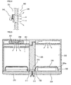
- Fig. 6 is a longitudinal sectional view of a barrier portion of a refrigerator according to a second embodiment of the present invention
- Fig. 7 is a cross-sectional view of an icemaker and an adjacent portion thereof in the refrigerator according to the second embodiment of the present invention.
- an adiabatic case 330 is installed at a chilling chamber door 304 of a chill chamber 302.
- An ice machine 320 is installed inside the adiabatic case 330 and an openable and closable adiabatic cover 331 is installed in front of the ice machine 320.
- a cooling air supply duct 310 and a cooling air discharge duct 315 are formed inside a barrier 305.
- a first cooling air inlet 311 is formed at one end of the cooling air supply duct 310 to communicate with a space where an evaporator 307 and a blower fan 308 are installed, and a first cooling air outlet 311 contacting the adiabatic case 330 is formed at the other end of the cooling air supply duct 310.
- the cooling air generated in the evaporator 307 is directly supplied to an adiabatic space 320a through the barrier 305 without being via the freezing chamber.
- the cooling air flowing to a cooling air supply duct 350 of the chilling chamber 302 is supplied to the chilling chamber 302 through a cooling air supply damper 351 of the chilling chamber 302 and a cooling air controller 352 of the chilling chamber 302.
- the cooling air supply damper 351 may be installed at a point where a cooling air supply passage is branched into the cooling air supply duct 350 and the cooling air supply duct 310.
- the cooling air supply damper 351 can adjust the amount of the cooling air introduced into the chilling chamber 302 and the amount of the cooling air supplied to an ice machine 320.
- the cooling air introduced into the adiabatic space 320a is supplied to an icemaker of the ice machine 320 and is used as the cooling air for the freezing, and then the cooling air is discharged through the cooling air discharge duct 315 via the third cooling air inlet 313.
- the cooling air flowing through the cooling air discharge duct 315 is again introduced into the evaporator 307, is heat-exchanged by the evaporator 307 and the blower fan 308, and is then again circulated.
- another cooling air discharge communicating with the freezing chamber may be formed inside the barrier 305, or another cooling air outlet communicating with the chilling chamber may be formed below the adiabatic case 330.
- the cooling air introduction passage is connected to the ice machine through the cooling air supply duct formed inside the barrier and the cooling air discharge passage is connected to the chilling chamber through an opening of the adiabatic case or is directly connected to the evaporator through the cooling air discharge duct inside the barrier.
- Another cooling air discharge passage is connected to the freezing chamber by penetrating the adiabatic case and the barrier, or is directly connected to the chilling chamber such that the cooling air used in the ice machine is directly discharged to the freezing chamber or the chilling chamber.
- At least one blower fan is installed on the cooling air circulation passage to increase the circulation amount of the cooling air.
- cooling air supply duct at an inside of an outer wall (right wall, lower wall, or upper wall) of the chilling chamber provided at an inner surface thereof with an adiabatic member not at the inside of the barrier partitioning the inner space of the refrigerator into the freezing chamber and the chilling chamber.
- cooling air discharge passage may be installed in relation to any of the return path of the evaporator, the freezing chamber and the chilling chamber in the aforementioned ice machine.
- the refrigerator and cooling air passage structure of the present invention since an ice machine is installed at a chilling chamber door, it is advantageous that the space of the freezing chamber increases. Also, by installing a cooling air circulation passage for circulating cooling air to the ice machine at the chilling chamber door, it is possible to efficiently control the cooling air used for the freezing.
Landscapes
- Engineering & Computer Science (AREA)
- Chemical & Material Sciences (AREA)
- Combustion & Propulsion (AREA)
- Physics & Mathematics (AREA)
- Mechanical Engineering (AREA)
- Thermal Sciences (AREA)
- General Engineering & Computer Science (AREA)
- Cold Air Circulating Systems And Constructional Details In Refrigerators (AREA)
- Devices That Are Associated With Refrigeration Equipment (AREA)
- Refrigerator Housings (AREA)
Description
- The present invention relates to a refrigerator according to the preamble of claim 1.
- Generally, a refrigerator is a machine to keep foods fresh for a predetermined time or freeze foods by lowering inner temperature thereof while refrigerant repeats a cooling cycle including compression, condensation, expansion and evaporation, and is one of life's necessities.
- At the present, the refrigerator shows a tendency to increase its volume, and various types of refrigerators such as a side-by-side type refrigerator having two doors are developed so as to meet consumers' demands. Such a two door refrigerator includes a freezing chamber and a chilling chamber and further includes an ice machine for freezing water to manufacture ice and extracting and receiving the manufactured ice.
- The ice machine includes an icemaker where ice is manufactured, an ice bank for storing the ice manufactured in the ice machine, an ice crusher for crushing the ice received in the ice bank and transferred thereinto, and ice dispenser for directly providing a user with the crushed ice. The ice machine is generally built in the freezing chamber of the refrigerator.
- The ice machine built in the freezing chamber of the refrigerator, however, occupies too much space in the freezing chamber. Thus, since the ice machine is installed at the door of the freezing chamber, consumers who use the receiving space of the freezing chamber frequently have inconvenience.
- Also, in the general side-by-side type refrigerator, since the freezing chamber is made smaller than the chilling chamber, the aforementioned inconvenience is conspicuous.
- [0006a] It is also known in the art the refrigerator of patent document JP06011228. This prior art refrigerator comprises a freezing chamber with a door for closing / opening the freezing chamber in witch is disposed an ice machine, this ice machine using space in the freezing chamber.
- Accordingly, the present invention is directed to a refrigerator and a cooling air passage structure thereof that substantially obviate one or more problems due to limitations and disadvantages of the related art.
- An object of the present invention is to provide a refrigerator and a cooling air passage structure thereof in which an ice machine is installed at a door of a chilling room to use the inner space of the chilling chamber more efficiently.
- Additional advantages, objects, and features of the invention will be set forth in part in the description which follows and in part will become apparent to those having ordinary skill in the art upon examination of the following or may be learned from practice of the invention. The objectives and other advantages of the invention may be realized and attained by the structure particularly pointed out in the written description and claims hereof as well as the appended drawings.
The object of the invention is achieved by a refrigerator as defined in claim 1. - It is to be understood that the following detailed description of the present invention is exemplary and explanatory and is intended to provide further explanation of the invention as claimed.
- The accompanying drawings, which are included to provide a further understanding of the invention and are incorporated in and constitute a part of this application, illustrate embodiment(s) of the invention and together with the description serve to explain the principle of the invention. In the drawings:
- Fig. 1 is a perspective view of a refrigerator according to a first embodiment of the present invention;
- Fig. 2 is a sectional view taken along the line I-I' of Fig. 1;
- Fig. 3 is a perspective view of a refrigerator of which door is opened according to the present invention;
- Fig. 4 is a sectional view taken along the line II-II' of Fig. 3;
- Fig. 5 is a sectional view taken along the line III-III' of Fig. 1;
- Fig. 6 is a longitudinal sectional view of a barrier portion of a refrigerator according to a second embodiment of the present invention; and
- Fig. 7 is a cross-sectional view of an icemaker and an adjacent portion thereof in the refrigerator according to the second embodiment of the present invention.
- Reference will now be made in detail to the preferred embodiments of the present invention, examples of which are illustrated in the accompanying drawings.
- First embodiment
- Fig. 1 is a perspective view of a refrigerator according to a first embodiment of the present invention, Fig. 2 is a sectional view taken along the line I-I' of Fig. 1, and Fig. 3 is a perspective view of a refrigerator of which door is opened according to the present invention.
- Referring to Figs. 1 through 3, the side-by-
side type refrigerator 200 includes afreezing chamber 201 for storing products in a frozen state, achilling chamber 202 for storing products in a chilled state, and abarrier 205 for partitioning an inner space of therefrigerator 200 into thefreezing chamber 201 of the left and thechilling chamber 202 of the right. Therefrigerator 200 also includes afreezing chamber door 203 disposed at a front side of thefreezing chamber 201, for opening and closing thefreezing chamber 201 and achilling chamber door 204 disposed at a front side of thechilling chamber 202, for opening and closing thechilling chamber 202. - In addition, a
manipulation part 100 is formed on an outer surface of thefreezing chamber door 203 to control the operation of therefrigerator 200. Anice dispenser 225 for dispensing ice is formed at an outer surface of thechilling chamber door 204 such that the manufactured ice is fed to the ice dispenser by a predetermined amount. To feed a proper amount of ice through theice dispenser 225, anice machine 220 is installed at a predetermined height of an inner portion of thechilling chamber door 204. - The
ice machine 220 is essentially provided with an icemaker 221 where ice is manufactured, and anice bank 222 for storing the manufactured ice. The ice machine is installed inside anadiabatic case 230. Specifically, theice machine 220 is installed at anadiabatic space 220a defined by theadiabatic case 230 disposed inside thechilling chamber door 204. Theadiabatic space 220a is adiabatically isolated from thechilling chamber 202 by anadiabatic cover 231. - In detail, the
ice machine 220 includes theicemaker 221 and theice bank 222. Theicemaker 221 is installed at an upper portion of theadiabatic space 220a to freeze fed water using cooling air for the freezing, thereby manufacturing ice. Theice bank 222 is installed at a lower portion of theadiabatic space 220a to store the ice extracted from theicemaker 221. Also, theice machine 220 includes anauger 223 for transferring and crushing the ice received in theice bank 222 and anice discharge hole 224 for discharging the ice received in theice bank 222. Theice dispenser 225 from which a user extracts the ice received in theice bank 222 is installed at the outer surface of thechilling chamber door 204. - The
adiabatic case 230 is installed inside thechilling chamber door 204 and has the openable and closableadiabatic cover 231 formed at one-sided portion thereof. To maintain a constant inner temperature, theadiabatic case 230 has an outer surface, which is coated with a material for reducing heat loss to or heat inflow from an outside. For example, the outer surface of theadiabatic case 230 is coated with polyurethane film. - Meanwhile, in order for the
ice machine 220 installed at thechilling chamber door 204 to perform a freezing operation, cooling air generated in an evaporator should be supplied as a cooling air for the freezing. It is preferable that the freezing air has a temperature below zero that the ice is not melted. The temperature of the cooling air for the freezing is set to be nearly the same as that of the cooling air of the freezing chamber. The present invention is characterized by providing a cooling air passage allowing the cooling air for the freezing to be properly supplied to theice machine 220. - Fig. 5 is a sectional view taken along the line III-III' of Fig. 1 and shows a cooling air passage structure for the freezing.
- Referring to Figs. 3 and 5, cooling air generated by an
evaporator 207 and ablower fan 208 installed at a rear wall of the refrigerator is supplied to theice machine 220 installed in thechilling chamber door 204 via thefreezing chamber 201 and thebarrier 205. The freezing air supplied to theice machine 220 is again circulated to thefreezing chamber 201. - In other words, the cooling air of the
freezing chamber 201 is introduced via thebarrier 205 and theadiabatic case 230 into theadiabatic space 220a where theice machine 220 is positioned. The cooling air used for the freezing in theice machine 220 is again discharged to thefreezing chamber 201 through theadiabatic case 230 and thebarrier 205. By the flow of the cooling air, the cooling air passage structure is defined. - The cooling air passage structure will now be described in detail.
- First, a cooling
air supply duct 210 is formed inside thebarrier 205 partitioning the inner space of the refrigerator into the leftfreezing chamber 201 and theright chilling chamber 202. One end of the coolingair supply duct 210 communicates with an inner space of thefreezing chamber 210 to form a firstcooling air inlet 211 and the other end of the coolingair supply duct 210 contacts theadiabatic case 230 to form a firstcooling air outlet 212. Like the coolingair supply duct 210, a coolingair discharge duct 215 is also formed at an inner space of thebarrier 205. One end of the coolingair discharge duct 215 communicates with an inner space of the freezingchamber 210 to form a thirdcooling air outlet 213 and the other end of the coolingair discharge duct 215 contacts theadiabatic case 230 to form a thirdcooling air inlet 214. - Also, a second
cooling air inlet 232 is formed at a predetermined portion of a side surface of theadiabatic case 230 corresponding to the firstcooling air outlet 212, and a secondcooling air outlet 233 is formed at a predetermined portion of the side surface of theadiabatic case 230 corresponding to the thirdcooling air inlet 213. - The
ice machine 220, i.e., flow of cooling air supplied to theadiabatic space 220a, will now be described with reference to the above cooling air passage structure. - The cooling air of the freezing
chamber 201 is introduced into the firstcooling air inlet 211, flows through an inside of the coolingair supply duct 210, and is then exhausted through the firstcooling air outlet 212. Then, the cooling air is introduced into the secondcooling air inlet 232 of theadiabatic case 230 closely contacting the firstcooling air outlet 212 and is used as the freezing air in theice machine 220. - After that, the cooling air used for the freezing is exhausted through the second
cooling air outlet 233 of theadiabatic case 230, is then introduced into the thirdcooling air inlet 213 formed in thebarrier 205, and flows through the inside of the coolingair discharge duct 215. Thereafter, the cooling air flowing through the inside of the coolingair discharge duct 215 is discharged to an inside of the freezingchamber 201 through the thirdcooling air outlet 214. - The cooling
air supply duct 210 is formed in the barrier to communicate the freezingchamber 201 with thechilling chamber 202. In other words, the cooling air of the freezingchamber 201 flows through the coolingair supply duct 210 of thebarrier 205, is introduced into the inside of theadiabatic case 230, and is then supplied to theice machine 220 disposed inside theadiabatic space 220a. Thus, the passage used for introducing the cooling air into theice machine 220 is referred to as 'a first cooling air introduction passage'. - The cooling air used for the freezing by the
ice machine 220 is introduced into the thirdcooling air inlet 213 through the secondcooling air outlet 233 of theadiabatic case 230, flows through the coolingair discharge duct 215, and is then discharged into the freezingchamber 201. Thus, the passage used for discharging the cooling air of theice machine 220 is referred to as 'a first cooling air discharge passage'. - Accordingly, the
icemaker 221 of theice machine 220 freezes the water fed thereinto using the cooling air introduced through thebarrier 205 and the coolingair inlet 232 of theadiabatic case 230 to manufacture ice. The manufactured ice drops into and is received in the ice bank 22. - The ice received in the ice bank 22 can be supplied to an outside of the refrigerator through the
ice dispenser 225 if necessary. - In a modification, it is possible not to recycle the cooling air supplied through the first cooling air introduction passage and used for the freezing in the
ice machine 220 to the freezingchamber 201 but to directly discharge the cooling air to thechilling chamber 202. For this purpose, it is possible to form a cooling air discharge hole (now shown) at a lower portion of theadiabatic case 230 such that the cooling air used in theice machine 220 is discharged to thechilling chamber 202 through the cooling air discharge hole of theadiabatic case 230. This cooling air discharge passage is discriminated from the first cooling air discharge passage and accordingly referred to as 'a second cooling air discharge passage'. - In other words, in a second cooling air circulation passage connecting the first cooling air introduction passage and the second cooling air discharge passage, the cooling air of the freezing chamber is introduced into the
adiabatic space 220a where theice machine 220 is installed, through thebarrier 205 and theadiabatic case 230 and the cooling air of the adiabatic space 22oa is introduced into thechilling chamber 202. The cooling air introduced into thechilling chamber 202 is supplied to the evaporator along a return path formed at thechilling chamber 202 to perform heat exchange using the evaporator and a blower fan, and the heat-exchanged cooling air can be again introduced into thechilling chamber 202. - As will be seen from the sectional view of Fig. 4 taken along the line II-II' of Fig. 3, a
blower fan 240 may be further provided in the coolingair supply duct 210 to increase and control the amount of the cooling air flowing into theice machine 220. Theblower fan 240 is operable when the temperature of the cooling air supplied to theice machine 220 is not sufficiently low or the supply amount of the cooling air is small. This case occurs when the cooling load of the ice machine is high or a large amount of cooling air is discharged through the first and second cooling air discharge passages. - Specifically, the
blower fan 240 is installed at the front side of the firstcooling air inlet 211 such that the cooling air of the freezingchamber 201 is easily discharged through the coolingair supply duct 210 of thebarrier 205. As theblower fan 240 is rotated by a motor, the amount of the cooling air of the freezingchamber 201 flowing through the cooling air circulation passage increases, so that the amount of the cooling air for the freezing flowing through the cooling air introduction passage and the cooling air discharge passage increases and the circulation period of the cooling air is shortened to enhance the freezing efficiency of theice machine 220. - In another modification, the
blower fan 240 may be installed at an inlet end of theadiabatic case 230. Alternatively, theblower fan 240 may be installed at an outlet end of theadiabatic case 230 or inside the coolingair supply duct 210 or the coolingair discharge duct 215. If theblower fan 240 is installed inside the coolingair supply duct 210 or the coolingair discharge duct 215, interference between outer parts does not occur and a graceful appearance can be obtained. - Also, the
blower fan 240 may be installed at two or more places. In other words, it is preferable that theblower fan 240 is installed on the cooling air introduction passage and the cooling air discharge passage at least one. In addition, theblower fan 240 is driven when the temperature of the cooling air supplied to theadiabatic space 220a is not sufficiently low, it is possible to enhance the freezing efficiency of theice machine 220. - In the meanwhile, a packing member, which is closely in contact with the
chilling chamber door 204 when thechilling chamber door 204 is opened or closed, is installed at a contact surface between the firstcooling air outlet 212 of thebarrier 205 and the secondcooling air inlet 232 of theadiabatic case 230, at a contact surface between the thirdcooling air outlet 213 of thebarrier 205 and the secondcooling air outlet 233 of theadiabatic case 230. - The packing member is made in a facing unevenness shape. That is, as shown in Fig. 5, the first
cooling air outlet 212 and the thirdcooling air inlet 213 are made in a groove shape and the secondcooling air inlet 232 and the secondcooling air outlet 233 are made in a protrusion shape. The groove of the firstcooling air outlet 212 and the thirdcooling air inlet 213 is engaged with the protrusion of the secondcooling air inlet 232 and the secondcooling air outlet 233 to form the unevenness shape, so that the firstcooling air outlet 212 and the thirdcooling air inlet 213 are closely in contact with the secondcooling air inlet 232 and the secondcooling air outlet 233. In addition, a sealing member such as a rubber or a gasket may be further formed around the unevenness shape. - Accordingly, it is advantageous that the cooling air is not leaked through each contact between the
adiabatic case 230 and thebarrier 205. - Second Embodiment
- The second embodiment of the present invention is characteristically different than the first embodiment in that cooling air having a temperature below zero is not via the freezing chamber but is directly supplied from the evaporator to the ice machine.
- Fig. 6 is a longitudinal sectional view of a barrier portion of a refrigerator according to a second embodiment of the present invention and Fig. 7 is a cross-sectional view of an icemaker and an adjacent portion thereof in the refrigerator according to the second embodiment of the present invention.
- Operation of a refrigerator according to the second embodiment of the present invention will now be described with reference to Figs. 6 and 7.
- Referring to Figs. 6 and 7, an
adiabatic case 330 is installed at achilling chamber door 304 of achill chamber 302. Anice machine 320 is installed inside theadiabatic case 330 and an openable and closableadiabatic cover 331 is installed in front of theice machine 320. - To form a cooling air circulation passage via the
ice machine 320, a coolingair supply duct 310 and a coolingair discharge duct 315 are formed inside abarrier 305. - A first
cooling air inlet 311 is formed at one end of the coolingair supply duct 310 to communicate with a space where anevaporator 307 and ablower fan 308 are installed, and a firstcooling air outlet 311 contacting theadiabatic case 330 is formed at the other end of the coolingair supply duct 310. By the above construction, the cooling air generated in theevaporator 307 is directly supplied to anadiabatic space 320a through thebarrier 305 without being via the freezing chamber. Also, the cooling air flowing to a coolingair supply duct 350 of thechilling chamber 302 is supplied to thechilling chamber 302 through a coolingair supply damper 351 of thechilling chamber 302 and a coolingair controller 352 of thechilling chamber 302. Alternatively, the coolingair supply damper 351 may be installed at a point where a cooling air supply passage is branched into the coolingair supply duct 350 and the coolingair supply duct 310. The coolingair supply damper 351 can adjust the amount of the cooling air introduced into thechilling chamber 302 and the amount of the cooling air supplied to anice machine 320. - The cooling air introduced into the
adiabatic space 320a is supplied to an icemaker of theice machine 320 and is used as the cooling air for the freezing, and then the cooling air is discharged through the coolingair discharge duct 315 via the thirdcooling air inlet 313. - The cooling air flowing through the cooling
air discharge duct 315 is again introduced into theevaporator 307, is heat-exchanged by theevaporator 307 and theblower fan 308, and is then again circulated. - In a modification of the second embodiment, another cooling air discharge communicating with the freezing chamber may be formed inside the
barrier 305, or another cooling air outlet communicating with the chilling chamber may be formed below theadiabatic case 330. - In the second embodiment described above, the cooling air introduction passage is connected to the ice machine through the cooling air supply duct formed inside the barrier and the cooling air discharge passage is connected to the chilling chamber through an opening of the adiabatic case or is directly connected to the evaporator through the cooling air discharge duct inside the barrier. Another cooling air discharge passage is connected to the freezing chamber by penetrating the adiabatic case and the barrier, or is directly connected to the chilling chamber such that the cooling air used in the ice machine is directly discharged to the freezing chamber or the chilling chamber.
- In addition, at least one blower fan is installed on the cooling air circulation passage to increase the circulation amount of the cooling air.
- Alternatively, in another embodiment, it is possible to form the cooling air supply duct at an inside of an outer wall (right wall, lower wall, or upper wall) of the chilling chamber provided at an inner surface thereof with an adiabatic member not at the inside of the barrier partitioning the inner space of the refrigerator into the freezing chamber and the chilling chamber. By designing the cooling air supply duct as above, it is obvious to those skilled in the art that the design of the cooling air inlet should be changed.
- Also, the cooling air discharge passage may be installed in relation to any of the return path of the evaporator, the freezing chamber and the chilling chamber in the aforementioned ice machine.
- While the proposed embodiments exemplarily show and describe the side-by-side type refrigerator, it will be apparent that various modifications and variations can be made in the present invention. Thus, it is intended that the present invention covers the modifications and variations of this invention provided they come within the scope of the appended claims and their equivalents.
- As described above, according to the refrigerator and cooling air passage structure of the present invention, since an ice machine is installed at a chilling chamber door, it is advantageous that the space of the freezing chamber increases. Also, by installing a cooling air circulation passage for circulating cooling air to the ice machine at the chilling chamber door, it is possible to efficiently control the cooling air used for the freezing.
- It will be apparent to those skilled in the art that various modifications and variations can be made in the present invention.
Claims (10)
- A refrigerator (200) comprising: a freezing chamber (201) for storing a product at a temperature below zero; a chilling chamber (202) for storing a product at a temperature above zero; a freezing chamber door (203) for opening and closing an entrance of the freezing chamber (201); a chilling chamber door (204) for opening and closing an entrance of the chilling chamber (202); a wall including therein an adiabatic member and for partitioning an inner space of the refrigerator into a chilling chamber (202) and a freezing chamber (201); and an evaporator for supplying a cooling air having a temperature below zero to the freezing chamber (201) and the chilling chamber (202) using evaporation of refrigerant,
the refrigerator being characterized by further including:an adiabatic case (230) formed at an inner portion of the chilling chamber door;an ice machine (220) installed inside the adiabatic case (230);an ice dispenser (225) formed at an outer portion of the chilling chamber door (204); anda pair of air passages(210) disposed inside the wall, each of the pair of air having one end communicating with an inside of the adiabatic case (230) and the other end communicating with an installation space of the evaporator (207),wherein the wall comprises a barrier (205) for partitioning an inner space of the refrigerator into the freezing chamber and the chilling chamber. - The refrigerator according to claim 1, wherein the barrier (205) is installed in a longitudinal direction of the refrigerator.
- The refrigerator according to claim 1, wherein one of the pair of air passages is a cooling air introduction passage extending to the adiabatic case (230) and the other one is a cooling air discharge passage extending from the adiabatic case (230).
- The refrigerator according to claim 1 or 3, wherein at least one of the pair of air passages has one end directly communicating with the freezing chamber (201).
- The refrigerator according to claim 1 or 3, wherein at least one of the pair of air passages (210) has one end directly communicating with an installation space of the evaporator (207).
- The refrigerator according to any of claims 1, 3, 4 and 5, wherein the adiabatic case has one end, which is opened and through which the cooling air used for the freezing inside the adiabatic case (230) is discharged to the chilling chamber (202).
- The refrigerator according to any of claims 1, 3, 4 and 5, wherein at least one of the pair of air passages has one end, which is branched a cooling air supply duct of the chilling chamber extending from the evaporator (207) to the chilling chamber (202).
- The refrigerator according to any of preceding claims, further comprising a fan for blowing cooling air for the freezing to an inside of the adiabatic case (230) or discharging the cooling air used for the freezing to an outside of the adiabatic case (230).
- The refrigerator according to any of preceding claims, further comprising an adiabatic cover (231) disposed on an inner surface of the adiabatic case (230) and freely openable and closable.
- The refrigerator according to claim 1, wherein the barrier (205) includes an air passage for supplying cooling air for water freezing to the ice machine (220).
Applications Claiming Priority (2)
| Application Number | Priority Date | Filing Date | Title |
|---|---|---|---|
| KR1020040005380A KR20050077844A (en) | 2004-01-28 | 2004-01-28 | Side by side type refrigerator |
| KR2004005380 | 2004-01-28 |
Publications (2)
| Publication Number | Publication Date |
|---|---|
| EP1559973A1 EP1559973A1 (en) | 2005-08-03 |
| EP1559973B1 true EP1559973B1 (en) | 2007-01-10 |
Family
ID=34651521
Family Applications (1)
| Application Number | Title | Priority Date | Filing Date |
|---|---|---|---|
| EP05290171A Expired - Lifetime EP1559973B1 (en) | 2004-01-28 | 2005-01-26 | Refrigerator and cooling air passage structure thereof |
Country Status (6)
| Country | Link |
|---|---|
| US (1) | US7240512B2 (en) |
| EP (1) | EP1559973B1 (en) |
| JP (1) | JP4694853B2 (en) |
| KR (1) | KR20050077844A (en) |
| CN (1) | CN1316216C (en) |
| DE (1) | DE602005000411T2 (en) |
Cited By (1)
| Publication number | Priority date | Publication date | Assignee | Title |
|---|---|---|---|---|
| US8746005B2 (en) | 2007-01-02 | 2014-06-10 | Lg Electronics Inc. | Refrigerator |
Families Citing this family (40)
| Publication number | Priority date | Publication date | Assignee | Title |
|---|---|---|---|---|
| EP1580504B1 (en) * | 2004-03-24 | 2017-03-29 | LG Electronics, Inc. | Cold air guide structure for ice-making chamber in cold chamber door |
| US7681406B2 (en) * | 2006-01-13 | 2010-03-23 | Electrolux Home Products, Inc. | Ice-making system for refrigeration appliance |
| CN101071027B (en) * | 2006-05-12 | 2010-05-12 | 泰州乐金电子冷机有限公司 | Electric refrigerator |
| CN101074818B (en) * | 2006-05-16 | 2010-10-13 | 泰州乐金电子冷机有限公司 | Refrigerator |
| KR100767844B1 (en) | 2006-07-11 | 2007-10-17 | 엘지전자 주식회사 | Refrigerator |
| KR101320767B1 (en) * | 2006-08-11 | 2013-10-21 | 엘지전자 주식회사 | Ice maker and refrigerator comprising the same |
| KR100716254B1 (en) * | 2006-08-18 | 2007-05-08 | 삼성전자주식회사 | Refrigerator |
| KR100780836B1 (en) * | 2006-09-12 | 2007-11-30 | 엘지전자 주식회사 | Ice bank fixing device for a refrigerator and a refrigerator including the same |
| US7614244B2 (en) * | 2006-12-21 | 2009-11-10 | General Electric Company | Ice producing apparatus and method |
| KR100809749B1 (en) * | 2007-03-28 | 2008-03-04 | 엘지전자 주식회사 | Ice Maker Assembly In Refrigerator |
| KR101339519B1 (en) * | 2007-07-31 | 2013-12-10 | 엘지전자 주식회사 | Refrigerator with refrigeration system of ice_making room installed in door |
| EP2131123A3 (en) * | 2008-03-12 | 2010-05-26 | Whirlpool Corporation | External tilt bucket |
| US8312735B2 (en) | 2008-03-12 | 2012-11-20 | Whirlpool Corporation | External tilt bucket for an appliance door |
| EP2159521A1 (en) * | 2008-08-27 | 2010-03-03 | Panasonic Corporation | Refrigerator |
| DE202008011437U1 (en) | 2008-08-27 | 2009-02-19 | Panasonic Corp., Kadoma | fridge |
| JP5202207B2 (en) * | 2008-09-19 | 2013-06-05 | 日立アプライアンス株式会社 | refrigerator |
| JP2010071565A (en) * | 2008-09-19 | 2010-04-02 | Hitachi Appliances Inc | Refrigerator |
| US20100326096A1 (en) * | 2008-11-10 | 2010-12-30 | Brent Alden Junge | Control sytem for bottom freezer refrigerator with ice maker in upper door |
| US9200828B2 (en) * | 2008-11-10 | 2015-12-01 | General Electric Company | Refrigerator |
| US8408016B2 (en) | 2010-04-27 | 2013-04-02 | Electrolux Home Products, Inc. | Ice maker with rotating ice mold and counter-rotating ejection assembly |
| CN102128534A (en) * | 2011-04-11 | 2011-07-20 | 合肥美的荣事达电冰箱有限公司 | Refrigeration equipment |
| CN102221276B (en) * | 2011-05-17 | 2013-01-09 | 合肥美的荣事达电冰箱有限公司 | Ice making device for refrigerator and refrigerator with same |
| CN102494460A (en) * | 2011-12-05 | 2012-06-13 | 海尔集团公司 | Refrigerator |
| WO2013183890A1 (en) | 2012-06-07 | 2013-12-12 | Samsung Electronics Co., Ltd. | Refrigerator |
| AU2014391330B2 (en) * | 2014-04-15 | 2017-10-12 | Mitsubishi Electric Corporation | Refrigerator |
| CN105444489A (en) * | 2015-12-02 | 2016-03-30 | 海信容声(广东)冰箱有限公司 | Refrigerator |
| KR102491598B1 (en) * | 2016-03-10 | 2023-01-26 | 삼성전자주식회사 | Refrigerator |
| CN106885419A (en) * | 2017-02-13 | 2017-06-23 | 合肥华凌股份有限公司 | A kind of refrigerator and ice making return air control method |
| US10663206B2 (en) * | 2017-06-13 | 2020-05-26 | Bsh Hausgeraete Gmbh | Household cooling appliance with specific external cooling of a sub-unit of the ice maker |
| US10712074B2 (en) | 2017-06-30 | 2020-07-14 | Midea Group Co., Ltd. | Refrigerator with tandem evaporators |
| US11346591B2 (en) | 2018-03-02 | 2022-05-31 | Electrolux Do Brasil S.A. | Single air passageway and damper assembly in a variable climate zone compartment |
| KR102529094B1 (en) * | 2018-04-05 | 2023-05-08 | 엘지전자 주식회사 | Vacuum adiabatic body and refrigerator |
| CN109780776B (en) * | 2018-11-20 | 2021-08-24 | 海尔智家股份有限公司 | Refrigerator and control method thereof |
| CN109612154B (en) * | 2019-01-17 | 2024-11-26 | 江苏热声机电科技有限公司 | Thermoacoustic Refrigeration Refrigerator |
| KR102720463B1 (en) * | 2019-02-01 | 2024-10-23 | 삼성전자주식회사 | Refrigerator |
| CN111520946B (en) * | 2019-02-02 | 2022-02-22 | 青岛海尔电冰箱有限公司 | Refrigerator with a door |
| CN114754529B (en) * | 2021-01-08 | 2023-07-14 | 青岛海尔电冰箱有限公司 | refrigerator |
| US11846462B2 (en) | 2021-03-19 | 2023-12-19 | Electrolux Home Products, Inc. | Door mounted chilled component with direct cooling |
| US11796242B2 (en) * | 2021-06-07 | 2023-10-24 | Haier Us Appliance Solutions, Inc. | Air vent for a refrigeration appliance |
| CN116792989B (en) * | 2022-03-17 | 2025-08-26 | 海信容声(广东)冰箱有限公司 | Refrigerator and water dispenser thereof |
Family Cites Families (16)
| Publication number | Priority date | Publication date | Assignee | Title |
|---|---|---|---|---|
| US3146601A (en) * | 1963-02-04 | 1964-09-01 | Gen Motors Corp | Refrigerating apparatus |
| US3788089A (en) | 1971-11-08 | 1974-01-29 | U Line Corp | Combination ice cube maker and refrigerator |
| US4003214A (en) | 1975-12-31 | 1977-01-18 | General Electric Company | Automatic ice maker utilizing heat pipe |
| US4872317A (en) | 1988-10-24 | 1989-10-10 | U-Line Corporation | Unitary ice maker with fresh food compartment and control system therefor |
| US5211462A (en) * | 1991-06-03 | 1993-05-18 | Sub-Zero Freezer Company, Inc. | Double door refrigerator with ice service through the refrigerator door |
| JPH0611228A (en) * | 1992-06-29 | 1994-01-21 | Hitachi Ltd | Refrigerator with automatic ice machine |
| US5375432A (en) * | 1993-12-30 | 1994-12-27 | Whirlpool Corporation | Icemaker in refrigerator compartment of refrigerator freezer |
| JP3747669B2 (en) | 1998-06-08 | 2006-02-22 | 三菱電機株式会社 | refrigerator |
| US6442954B1 (en) * | 2001-07-02 | 2002-09-03 | General Electric Company | Dual hopper icemaking refrigerator |
| TW571066B (en) * | 2001-10-12 | 2004-01-11 | Toshiba Corp | Refrigerator |
| KR100432752B1 (en) * | 2002-05-31 | 2004-05-24 | 엘지전자 주식회사 | Refrigerator |
| CN1211621C (en) * | 2002-06-06 | 2005-07-20 | 乐金电子(天津)电器有限公司 | Ice-making machine for refrigerator |
| US6735959B1 (en) * | 2003-03-20 | 2004-05-18 | General Electric Company | Thermoelectric icemaker and control |
| US6964177B2 (en) | 2003-05-28 | 2005-11-15 | Lg Electronics Inc. | Refrigerator with icemaker |
| KR100565621B1 (en) | 2003-09-19 | 2006-03-29 | 엘지전자 주식회사 | Refrigerator |
| KR100565622B1 (en) | 2003-09-19 | 2006-03-30 | 엘지전자 주식회사 | Refrigerator |
-
2004
- 2004-01-28 KR KR1020040005380A patent/KR20050077844A/en not_active Ceased
-
2005
- 2005-01-26 DE DE602005000411T patent/DE602005000411T2/en not_active Expired - Lifetime
- 2005-01-26 EP EP05290171A patent/EP1559973B1/en not_active Expired - Lifetime
- 2005-01-28 US US11/043,972 patent/US7240512B2/en not_active Expired - Lifetime
- 2005-01-28 JP JP2005021526A patent/JP4694853B2/en not_active Expired - Lifetime
- 2005-01-28 CN CNB2005100061400A patent/CN1316216C/en not_active Expired - Lifetime
Cited By (1)
| Publication number | Priority date | Publication date | Assignee | Title |
|---|---|---|---|---|
| US8746005B2 (en) | 2007-01-02 | 2014-06-10 | Lg Electronics Inc. | Refrigerator |
Also Published As
| Publication number | Publication date |
|---|---|
| JP4694853B2 (en) | 2011-06-08 |
| EP1559973A1 (en) | 2005-08-03 |
| CN1316216C (en) | 2007-05-16 |
| US20050178145A1 (en) | 2005-08-18 |
| US7240512B2 (en) | 2007-07-10 |
| DE602005000411T2 (en) | 2007-05-16 |
| KR20050077844A (en) | 2005-08-04 |
| DE602005000411D1 (en) | 2007-02-22 |
| JP2005214622A (en) | 2005-08-11 |
| CN1648564A (en) | 2005-08-03 |
Similar Documents
| Publication | Publication Date | Title |
|---|---|---|
| US7240512B2 (en) | Refrigerator and cooling air passage structure thereof | |
| EP3705818B1 (en) | Refrigerator | |
| US7240511B2 (en) | Cold air path structure of refrigerator | |
| EP1580504B1 (en) | Cold air guide structure for ice-making chamber in cold chamber door | |
| US7484382B2 (en) | Refrigerator | |
| CN102395843B (en) | Refrigerator related technology | |
| US20110100046A1 (en) | Refrigerator | |
| CN118565129A (en) | refrigerator | |
| KR100607288B1 (en) | Cold air flow path structure for ice making of side by side type refrigerator | |
| KR19990008562A (en) | Cold air supply structure of the refrigerator |
Legal Events
| Date | Code | Title | Description |
|---|---|---|---|
| PUAI | Public reference made under article 153(3) epc to a published international application that has entered the european phase |
Free format text: ORIGINAL CODE: 0009012 |
|
| AK | Designated contracting states |
Kind code of ref document: A1 Designated state(s): AT BE BG CH CY CZ DE DK EE ES FI FR GB GR HU IE IS IT LI LT LU MC NL PL PT RO SE SI SK TR |
|
| AX | Request for extension of the european patent |
Extension state: AL BA HR LV MK YU |
|
| 17P | Request for examination filed |
Effective date: 20051208 |
|
| RIN1 | Information on inventor provided before grant (corrected) |
Inventor name: LEE, MYUNG RYUL Inventor name: KWON, YONG CHOL Inventor name: LEE, WOOK YOUNG Inventor name: CHUNG, EUI YEOP Inventor name: OH, SEUNG HWAN Inventor name: KIM, SEONG OOK Inventor name: KIM, SHIN, III |
|
| RIN1 | Information on inventor provided before grant (corrected) |
Inventor name: KIM, SHIN, III Inventor name: CHUNG, EUI YEOP Inventor name: KWON, YONG CHOL Inventor name: LEE, WOOK YOUNG Inventor name: LEE, MYUNG RYUL Inventor name: KIM, SEONG OOK Inventor name: OH, SEUNG HWAN |
|
| AKX | Designation fees paid |
Designated state(s): DE FR GB |
|
| GRAP | Despatch of communication of intention to grant a patent |
Free format text: ORIGINAL CODE: EPIDOSNIGR1 |
|
| GRAS | Grant fee paid |
Free format text: ORIGINAL CODE: EPIDOSNIGR3 |
|
| GRAA | (expected) grant |
Free format text: ORIGINAL CODE: 0009210 |
|
| AK | Designated contracting states |
Kind code of ref document: B1 Designated state(s): DE FR GB |
|
| REG | Reference to a national code |
Ref country code: GB Ref legal event code: FG4D |
|
| REF | Corresponds to: |
Ref document number: 602005000411 Country of ref document: DE Date of ref document: 20070222 Kind code of ref document: P |
|
| ET | Fr: translation filed | ||
| PLBE | No opposition filed within time limit |
Free format text: ORIGINAL CODE: 0009261 |
|
| STAA | Information on the status of an ep patent application or granted ep patent |
Free format text: STATUS: NO OPPOSITION FILED WITHIN TIME LIMIT |
|
| 26N | No opposition filed |
Effective date: 20071011 |
|
| REG | Reference to a national code |
Ref country code: FR Ref legal event code: PLFP Year of fee payment: 12 |
|
| REG | Reference to a national code |
Ref country code: FR Ref legal event code: PLFP Year of fee payment: 13 |
|
| REG | Reference to a national code |
Ref country code: FR Ref legal event code: PLFP Year of fee payment: 14 |
|
| P01 | Opt-out of the competence of the unified patent court (upc) registered |
Effective date: 20230523 |
|
| PGFP | Annual fee paid to national office [announced via postgrant information from national office to epo] |
Ref country code: GB Payment date: 20231207 Year of fee payment: 20 |
|
| PGFP | Annual fee paid to national office [announced via postgrant information from national office to epo] |
Ref country code: FR Payment date: 20231206 Year of fee payment: 20 |
|
| PGFP | Annual fee paid to national office [announced via postgrant information from national office to epo] |
Ref country code: DE Payment date: 20231205 Year of fee payment: 20 |
|
| REG | Reference to a national code |
Ref country code: DE Ref legal event code: R071 Ref document number: 602005000411 Country of ref document: DE |
|
| REG | Reference to a national code |
Ref country code: GB Ref legal event code: PE20 Expiry date: 20250125 |
|
| PG25 | Lapsed in a contracting state [announced via postgrant information from national office to epo] |
Ref country code: GB Free format text: LAPSE BECAUSE OF EXPIRATION OF PROTECTION Effective date: 20250125 |