EP1559947A2 - Panel mounting unit - Google Patents
Panel mounting unit Download PDFInfo
- Publication number
- EP1559947A2 EP1559947A2 EP05001672A EP05001672A EP1559947A2 EP 1559947 A2 EP1559947 A2 EP 1559947A2 EP 05001672 A EP05001672 A EP 05001672A EP 05001672 A EP05001672 A EP 05001672A EP 1559947 A2 EP1559947 A2 EP 1559947A2
- Authority
- EP
- European Patent Office
- Prior art keywords
- mounting
- display panel
- pivot
- arm
- support
- Prior art date
- Legal status (The legal status is an assumption and is not a legal conclusion. Google has not performed a legal analysis and makes no representation as to the accuracy of the status listed.)
- Withdrawn
Links
Images


Classifications
-
- F—MECHANICAL ENGINEERING; LIGHTING; HEATING; WEAPONS; BLASTING
- F16—ENGINEERING ELEMENTS AND UNITS; GENERAL MEASURES FOR PRODUCING AND MAINTAINING EFFECTIVE FUNCTIONING OF MACHINES OR INSTALLATIONS; THERMAL INSULATION IN GENERAL
- F16M—FRAMES, CASINGS OR BEDS OF ENGINES, MACHINES OR APPARATUS, NOT SPECIFIC TO ENGINES, MACHINES OR APPARATUS PROVIDED FOR ELSEWHERE; STANDS; SUPPORTS
- F16M11/00—Stands or trestles as supports for apparatus or articles placed thereon ; Stands for scientific apparatus such as gravitational force meters
- F16M11/20—Undercarriages with or without wheels
- F16M11/22—Undercarriages with or without wheels with approximately constant height, e.g. with constant length of column or of legs
-
- F—MECHANICAL ENGINEERING; LIGHTING; HEATING; WEAPONS; BLASTING
- F16—ENGINEERING ELEMENTS AND UNITS; GENERAL MEASURES FOR PRODUCING AND MAINTAINING EFFECTIVE FUNCTIONING OF MACHINES OR INSTALLATIONS; THERMAL INSULATION IN GENERAL
- F16M—FRAMES, CASINGS OR BEDS OF ENGINES, MACHINES OR APPARATUS, NOT SPECIFIC TO ENGINES, MACHINES OR APPARATUS PROVIDED FOR ELSEWHERE; STANDS; SUPPORTS
- F16M11/00—Stands or trestles as supports for apparatus or articles placed thereon ; Stands for scientific apparatus such as gravitational force meters
- F16M11/02—Heads
- F16M11/04—Means for attachment of apparatus; Means allowing adjustment of the apparatus relatively to the stand
- F16M11/06—Means for attachment of apparatus; Means allowing adjustment of the apparatus relatively to the stand allowing pivoting
- F16M11/10—Means for attachment of apparatus; Means allowing adjustment of the apparatus relatively to the stand allowing pivoting around a horizontal axis
-
- F—MECHANICAL ENGINEERING; LIGHTING; HEATING; WEAPONS; BLASTING
- F16—ENGINEERING ELEMENTS AND UNITS; GENERAL MEASURES FOR PRODUCING AND MAINTAINING EFFECTIVE FUNCTIONING OF MACHINES OR INSTALLATIONS; THERMAL INSULATION IN GENERAL
- F16M—FRAMES, CASINGS OR BEDS OF ENGINES, MACHINES OR APPARATUS, NOT SPECIFIC TO ENGINES, MACHINES OR APPARATUS PROVIDED FOR ELSEWHERE; STANDS; SUPPORTS
- F16M13/00—Other supports for positioning apparatus or articles; Means for steadying hand-held apparatus or articles
- F16M13/02—Other supports for positioning apparatus or articles; Means for steadying hand-held apparatus or articles for supporting on, or attaching to, an object, e.g. tree, gate, window-frame, cycle
-
- F—MECHANICAL ENGINEERING; LIGHTING; HEATING; WEAPONS; BLASTING
- F16—ENGINEERING ELEMENTS AND UNITS; GENERAL MEASURES FOR PRODUCING AND MAINTAINING EFFECTIVE FUNCTIONING OF MACHINES OR INSTALLATIONS; THERMAL INSULATION IN GENERAL
- F16M—FRAMES, CASINGS OR BEDS OF ENGINES, MACHINES OR APPARATUS, NOT SPECIFIC TO ENGINES, MACHINES OR APPARATUS PROVIDED FOR ELSEWHERE; STANDS; SUPPORTS
- F16M2200/00—Details of stands or supports
- F16M2200/04—Balancing means
- F16M2200/041—Balancing means for balancing rotational movement of the head
Definitions
- This invention relates to a panel mounting unit and for a combination there of with a unit. It is particularly concerned with a unit whereby a display panel can be mounted on a surface or other supporting means.
- a display panel of this type is characterised by having width and vertical depth dimensions which are considerably greater than the thickness of the panel.
- the width and depth dimensions of modem panels can be of the order of several hundreds of millimetres.
- the panel can be positioned to operate in a portrait or landscape configuration.
- the panel itself can be heavy and this, taken in combination with its size, can make it difficult to manipulate during installation. A security requirement can arise since a display panel is an expensive item liable to theft or tampering.
- a display panel mounting unit comprising a mounting plate and at least two mounting supports; the mounting plate, providing for the attachment of the unit to a wall or other support; the mounting plate including first and second attachment means to which the mounting supports are attached; each, mounting support comprising a first longitudinal member incorporating means whereby the member can be attached to a display panel for mounting; and a second longitudinal member pivotably attached to the first by means of a pivot so as to provide an axis of rotation of the second member relative to the first member; the second member comprising a first arm on one side of the pivot and a second arm on the other side of the pivot; the first arm having at, or near, an end remote from the pivot an anchorage and a first means for retaining the mounting support on the first attachment means on the mounting plate; the second arm having at, or near, an end remote from the pivot a second means for retaining the mounting support on the second attachment means on the mounting plate; a compression means extending between a location on the first member and the anchorage
- the means whereby the first longitudinal member can be attached to a display panel for mounting comprise at least one longitudinal slot in the first longitudinal member.
- the, or each, slot is provided with an associated clip mounting by means of which a bolt can be positioned in a predetermined location in the slot.
- the slot is provided with a series of recesses at intervals along its length and the associated clip is provided with a projection whereby the clip can engage with a selected recess in the series to locate the clip at a predetermined position in the slot relative to a display panel for mounting on the first member.
- the unit includes means whereby the first member can be displaced about the axis of rotation relative to the second member by means operable remotely from the unit.
- an assembly comprising in combination a display panel and a display panel mounting unit according to the first aspect or of any preferred version thereof.
- first member can be displaced about the axis of rotation relative to the second member by means operable remotely from the unit.
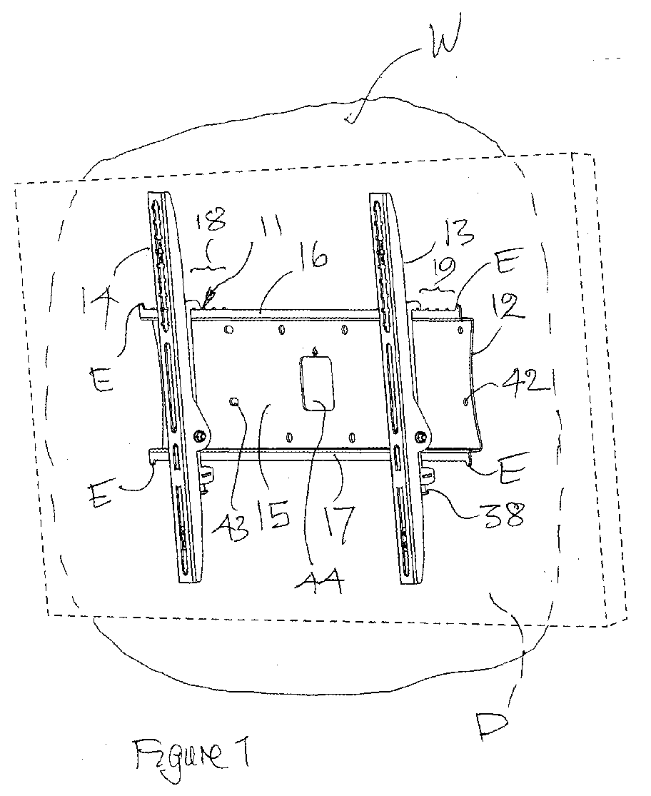
- the figures variously show a panel mounting device 11 comprising a mounting plate 12 and, in this case, two mounting supports 13, 14.
- a display panel D is shown in broken outline.
- the mounting plate 12 provides for the attachment of the device 11 to a wall W.
- the plate 12 has a body section 15 with two attachment means comprising a projecting L-shaped upper support flange 16 and an L-shaped lower support flange 17.
- the upper flange 16 is provided towards either end region with a series of projections 18, 19, for location purposes as will be described hereafter, and with end stops E.
- the mounting supports 13, 14 are identical in form, components and function and so hereafter detailed reference will only be made to support 13.
- Figures 3 to 6 variously show a support 13 comprising a first longitudinal member 20, of channel section, for securing to the rear of the display panel D (shown in broken outline) selected from a variety of panels available from a number of manufacturers.
- the first member 20 is provided with a universal fitting providing for the accommodation of a variety of panels comprising; first slot 21 with associated first mounting clip 22, a second slot 23 with associated second mounting clip 24; and central slot C1 for a centre mounting means, such as a bolt, for a panel.
- First slot 21 is provided with a series of punched pairs of lateral slots, typically slot 25, into a selected one of which projecting lugs 26 of first mounting clip 22 can be inserted.
- the first clip 22 is provided with holes 27 through which bolt B is placed to engage with to a complementary threaded socket in the panel D so enabling the first member 20 to be clamped to the upper part of the panel D.
- second slot 23 is un-slotted by comparison with first slot 21 to provide an infinitely variable location for a bolt B' located in the slot 23 by means of second clip 24 relative to bolt B in a fixed location in slot 21.
- Second clip 24 is provided with holes 28 through which a bolt is placed in order to secure the clip 24 to a complementary threaded recess in the panel D and so enabling the first member 20 to be clamped to the lower part of the panel D.
- a bush W1 of insulating material is located in slot 21 and/or C1 as appropriate so that bolt BB extends through the W1 into the panel D.
- bush W2 of insulating material is located in slot 23, and/or C1, as appropriate so that bolt BB' extends through the W1 into the panel D.
- Second longitudinal member 29 is of channel section with side walls 29X, 29Y, and base 29Z.
- the second member 29 is pivotably attached to the first member 20 by means of a bolt 30 located in trunnions 31, 32 formed integrally with first member 20.
- the bolt 30 provides for a pivot axis of rotation 33 of the second member 29 relative to the first member 20.
- a pivot bolt 30 extends through Bellville washer 30B, trunnion 31, nylon washer 30C, through second member 29, nylon washer 30D, trunnions 30E, Belleville washer 30F finally engaging with nut 30G.
- the second member 29 On assembly of the support member 13 it is necessary to tighten up the bolt 30A to provide the appropriate loading to ensure the second member 29 pivots smoothly.
- the second member 29 has two integral stiffeners S1, S2 extending between walls 29X, 29Y of the channel from which the member 29 is formed.
- the stiffeners S1, S2 are formed by bending cut-outs formed in the base 29Z of the channel.
- the second member 29 extends longitudinally on either side of the bolt 30 to provide a first arm 29A above the bolt 30 and a second arm 29B below the bolt 30.
- the first arm 29A has near an end 34 remote from the bolt 30 a pair of hooks 35 providing for the retention of the support arm 13 on the upper flange 16 of the mounting plate 12.
- the second arm 29B towards end Z remote from the axis 33 includes an anchorage 36 in which is mounted a bush 37 through which bolt 38 extends to provide a lower means for clamping the second member 29 to flange 17 on the mounting plate 12 by way of the bolt 38.
- the anchorage 36 is not at right angles to base 29Z of the channel but is canted so that the leading end of the bolt 38 when bolt 38 is tightened to engage a flange 17 on mounting plate 12 tends to draw the second member 29 into closer engagement with the mounting plate flange.
- Compression spring 39 extends between a location 40 on the first member 20 and the anchorage 36.
- the compression spring 28 acts to resiliently bias the anchorage 36, and so the end Z of the second arm 29B, away from the first member 20.
- the first arm 29A is longer than the second arm 29B so that rotation of the end 29B has a reasonable arc of travel into and out of the channel section of first member 20 when the second member 29 is pivoting about axis 33 relative to first member 20.
- a greater arc of movement can be achieved as will be referred to later.
- the compression spring 39 together with a corresponding spring in the support arm 14 have a combined spring rate such that the weight of the combination of the second member 29 and panel D provide a moment tending to pivot the combination in a first direction about the pivot axis 33. This is balanced by a second moment generated by the action of the compression spring 39 on the anchorage 36 of the about the pivot axis 33 in the opposite direction to the given direction.
- the range of angular rotation available in this case is about 11 degrees. The combination is readily moved throughout this range with a smooth and light movement.
- the plate 12 is secured to the wall W by conventional means.
- the body section 15 of the plate 12 is fabricated with several holes and slots , typically hole 42 and slot 43, through which a retaining device can be driven.
- a central aperture 44 enable a power supply and data cable to be fed to the panel from a wall source so that the cable is concealed from view and to some extent protected against tampering.
- the supports 13, 14 are then mounted, by way of their respective first longitudinal members, on the panel D and secured in place as described earlier.
- the end stops E quite apart from the sequence of projections 18, 19, serve to resist attempts to slide the panel D and support members 13, 14 laterally from the plate 12.
- the exemplary embodiment describes a system for mounting a display panel D which while secured in location can be readily rotated about axis 33 over an arc until a selected viewing position is reached when the panel D can be released whereupon it remains in place.
- a cable can be provided with one end attached to the screen and the other end located so that the cable can be used to pivot the screen to the required viewing angle.
- the pivot axis 33 lies relatively close to the base of the channel forming first member 20.
- the angular displacement available of the member 29 about pivot axis 33 is limited.
- the pivot axis 33 can be moved outwardly away from the first member 20 by having trunnions 31, 32 of greater depth so that the holes in the trunnions through which bolt 30 passes are further away from the base of the channel forming first member 20.
- the outboard end of arm 29B has a greater arc of movement and to the panel D can be positioned anywhere over a longer arc.
- a consequential change will need to be made in the dimensions and rate of the spring 39 of support member 13 and the corresponding spring in support member 14..
Landscapes
- Engineering & Computer Science (AREA)
- General Engineering & Computer Science (AREA)
- Mechanical Engineering (AREA)
- Devices For Indicating Variable Information By Combining Individual Elements (AREA)
Abstract
Description
- This invention relates to a panel mounting unit and for a combination there of with a unit. It is particularly concerned with a unit whereby a display panel can be mounted on a surface or other supporting means.
- It is known to mount an electronic information display panel on a wall or other support to provide for ready viewing of the panel. Such a panel has an active display component which can be, for example, a plasma panel, light emitting diodes or liquid crystal display. A display panel of this type is characterised by having width and vertical depth dimensions which are considerably greater than the thickness of the panel. The width and depth dimensions of modem panels can be of the order of several hundreds of millimetres. The panel can be positioned to operate in a portrait or landscape configuration. The panel itself can be heavy and this, taken in combination with its size, can make it difficult to manipulate during installation. A security requirement can arise since a display panel is an expensive item liable to theft or tampering.
- According to a first aspect of the present invention there is provided a display panel mounting unit comprising a mounting plate and at least two mounting supports;
the mounting plate, providing for the attachment of the unit to a wall or other support; the mounting plate including first and second attachment means to which the mounting supports are attached;
each, mounting support comprising
a first longitudinal member incorporating means whereby the member can be attached to a display panel for mounting; and
a second longitudinal member pivotably attached to the first by means of a pivot so as to provide an axis of rotation of the second member relative to the first member; the second member comprising a first arm on one side of the pivot and a second arm on the other side of the pivot; the first arm having at, or near, an end remote from the pivot an anchorage and a first means for retaining the mounting support on the first attachment means on the mounting plate; the second arm having at, or near, an end remote from the pivot a second means for retaining the mounting support on the second attachment means on the mounting plate; a compression means extending between a location on the first member and the anchorage of the second member; the compression means serving to resiliently bias the anchorage, and so the end of the second arm remote from the pivot, away from the location on the first member; the compression means providing that with a combination comprising a display panel secured to the first longitudinal member an the combination attached to the second member by way of the pivot and the second member clamped to the mounting plate then a first moment generated by the weight of the combination about the pivot axis in a given direction of rotation is balanced by a second moment generated by the action of the compression means on the first arm about the pivot axis in the opposite direction to the given direction. - According to a first preferred version of the first aspect of the present invention the means whereby the first longitudinal member can be attached to a display panel for mounting comprise at least one longitudinal slot in the first longitudinal member. Typically the, or each, slot is provided with an associated clip mounting by means of which a bolt can be positioned in a predetermined location in the slot. Preferably the slot is provided with a series of recesses at intervals along its length and the associated clip is provided with a projection whereby the clip can engage with a selected recess in the series to locate the clip at a predetermined position in the slot relative to a display panel for mounting on the first member.
- According to a second preferred version of the first aspect of the present invention or of any preceding preferred version thereof the unit includes means whereby the first member can be displaced about the axis of rotation relative to the second member by means operable remotely from the unit.
- According to a second aspect of the present invention there is provided an assembly comprising in combination a display panel and a display panel mounting unit according to the first aspect or of any preferred version thereof.
- According to a first preferred version of the second aspect of the present invention means are provided whereby the first member can be displaced about the axis of rotation relative to the second member by means operable remotely from the unit.
- An exemplary embodiment of the invention will now be described with reference to the accompanying drawings of a panel mounting device of which:
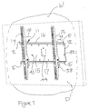
- Figure 1 perspective view from the front;
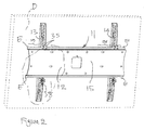
- Figure 2 is perspective view from the rear;
- Figure 3A is an exploded view of a component of Figure 2;
- Figure 3B is an assembled view of the components shown in Figure 3A with additional components; and
- Figure 4 is an enlarged detail of Figure 3B; and
- Figure 5 is a further view of a component shown in Figures 3A and 3B.
-
- The figures variously show a
panel mounting device 11 comprising amounting plate 12 and, in this case, two mounting supports 13, 14. A display panel D is shown in broken outline. Themounting plate 12 provides for the attachment of thedevice 11 to a wall W. Theplate 12 has abody section 15 with two attachment means comprising a projecting L-shapedupper support flange 16 and an L-shapedlower support flange 17. Theupper flange 16 is provided towards either end region with a series ofprojections 18, 19, for location purposes as will be described hereafter, and with end stops E. - The mounting supports 13, 14 are identical in form, components and function and so hereafter detailed reference will only be made to support 13.
- Figures 3 to 6 variously show a
support 13 comprising a firstlongitudinal member 20, of channel section, for securing to the rear of the display panel D (shown in broken outline) selected from a variety of panels available from a number of manufacturers. To this end thefirst member 20 is provided with a universal fitting providing for the accommodation of a variety of panels comprising;
first slot 21 with associatedfirst mounting clip 22,
asecond slot 23 with associatedsecond mounting clip 24; and
central slot C1 for a centre mounting means, such as a bolt, for a panel. -
First slot 21 is provided with a series of punched pairs of lateral slots, typicallyslot 25, into a selected one of which projectinglugs 26 offirst mounting clip 22 can be inserted. Thefirst clip 22 is provided withholes 27 through which bolt B is placed to engage with to a complementary threaded socket in the panel D so enabling thefirst member 20 to be clamped to the upper part of the panel D. - As shown particularly in Figure 3B
second slot 23 is un-slotted by comparison withfirst slot 21 to provide an infinitely variable location for a bolt B' located in theslot 23 by means ofsecond clip 24 relative to bolt B in a fixed location inslot 21.Second clip 24 is provided withholes 28 through which a bolt is placed in order to secure theclip 24 to a complementary threaded recess in the panel D and so enabling thefirst member 20 to be clamped to the lower part of the panel D. - In the event that a panel D is to be mounted so as to be electrically isolated from
first member 20, and so from thewhole unit 11, a bush W1 of insulating material is located inslot 21 and/or C1 as appropriate so that bolt BB extends through the W1 into the panel D. Likewise bush W2 of insulating material is located inslot 23, and/or C1, as appropriate so that bolt BB' extends through the W1 into the panel D. - In this way loading applied by means of the bolt to clamp the
first member 13 to is solely by way of the insulating bushes W1, W2 as aforesaid. - Second
longitudinal member 29 is of channel section withside walls 29X, 29Y, and base 29Z. Thesecond member 29 is pivotably attached to thefirst member 20 by means of a bolt 30 located in trunnions 31, 32 formed integrally withfirst member 20. The bolt 30 provides for a pivot axis ofrotation 33 of thesecond member 29 relative to thefirst member 20. - With particular reference to Figure 3A a pivot bolt 30 extends through Bellville washer 30B, trunnion 31, nylon washer 30C, through
second member 29, nylon washer 30D, trunnions 30E, Bellevillewasher 30F finally engaging with nut 30G. On assembly of thesupport member 13 it is necessary to tighten up the bolt 30A to provide the appropriate loading to ensure thesecond member 29 pivots smoothly. To ensure that the loading does not distort thesecond member 29 in the vicinity ofpivot axis 33 of bolt 30 thesecond member 29 has two integral stiffeners S1, S2 extending betweenwalls 29X, 29Y of the channel from which themember 29 is formed. The stiffeners S1, S2 are formed by bending cut-outs formed in the base 29Z of the channel. - The
second member 29 extends longitudinally on either side of the bolt 30 to provide afirst arm 29A above the bolt 30 and a second arm 29B below the bolt 30. Thefirst arm 29A has near anend 34 remote from the bolt 30 a pair ofhooks 35 providing for the retention of thesupport arm 13 on theupper flange 16 of themounting plate 12. - The second arm 29B towards end Z remote from the
axis 33 includes ananchorage 36 in which is mounted abush 37 through whichbolt 38 extends to provide a lower means for clamping thesecond member 29 toflange 17 on themounting plate 12 by way of thebolt 38. Theanchorage 36 is not at right angles to base 29Z of the channel but is canted so that the leading end of thebolt 38 whenbolt 38 is tightened to engage aflange 17 onmounting plate 12 tends to draw thesecond member 29 into closer engagement with the mounting plate flange. -
Compression spring 39 extends between a location 40 on thefirst member 20 and theanchorage 36. Thecompression spring 28 acts to resiliently bias theanchorage 36, and so the end Z of the second arm 29B, away from thefirst member 20. - The
first arm 29A is longer than the second arm 29B so that rotation of the end 29B has a reasonable arc of travel into and out of the channel section offirst member 20 when thesecond member 29 is pivoting aboutaxis 33 relative tofirst member 20. A greater arc of movement can be achieved as will be referred to later. - The
compression spring 39 together with a corresponding spring in thesupport arm 14 have a combined spring rate such that the weight of the combination of thesecond member 29 and panel D provide a moment tending to pivot the combination in a first direction about thepivot axis 33. This is balanced by a second moment generated by the action of thecompression spring 39 on theanchorage 36 of the about thepivot axis 33 in the opposite direction to the given direction. Thus regardless of the position of combination relative to theaxis 33 the combination is not subject to a significant rotary displacement and tends to remain in a position in which it is left. The range of angular rotation available in this case is about 11 degrees. The combination is readily moved throughout this range with a smooth and light movement. - To provide for the mounting of display panel D on wall W (see Figure 1) the
plate 12 is secured to the wall W by conventional means. To facilitate this thebody section 15 of theplate 12 is fabricated with several holes and slots , typically hole 42 and slot 43, through which a retaining device can be driven. Acentral aperture 44 enable a power supply and data cable to be fed to the panel from a wall source so that the cable is concealed from view and to some extent protected against tampering. - The supports 13, 14 are then mounted, by way of their respective first longitudinal members, on the panel D and secured in place as described earlier.
- Thereafter the combination of panel D and supports 13 and 14 are presented to the
plate 12 and the pair ofhooks 35 onarm 29A and the corresponding pair of hooks onsupport 14 are hooked overupper flange 16 to seat symmetrically relative to theplate 12. Thehooks 35 are seated so that they are juxtaposed with projections in sequence 19 to limit sliding of the combination relative to theplate 12. 18 and to provide for the D to be laterally mounted symmetrically on theplate 12. This initial hooking over step is readily achieved even with limited or unstable access only being available to the operator. - The combination of panel D and
support members plate 12 by tightening upbolt 38 onsupport 13, and the corresponding bolt onsupport 14, so that the lower part of eachsupport lower flange 17 of theplate 12. The angled alignment of thebolt 38 ensures that as the bolt is tightened it tends to move into the apex of theflange 17 so tending to draw the second member 29 (and the corresponding member ofsupport 14 more closely to theplate 12. Figure 4 shows the relative positions of components in the lower part ofsupport member 13 once the bolting operation is completed. In this figure the wall W is not shown for the sake of clarity. - To combat unauthorised removal or tampering the shape of the
flanges hooks 35 andbolt 38 onsupport 13 and the corresponding elements onsupport 14 serve to prevent the combination ofsupport - The end stops E, quite apart from the sequence of
projections 18, 19, serve to resist attempts to slide the panel D andsupport members plate 12. - The exemplary embodiment describes a system for mounting a display panel D which while secured in location can be readily rotated about
axis 33 over an arc until a selected viewing position is reached when the panel D can be released whereupon it remains in place. - In the event the display panel is mounted in a location to which limited access is available in order to manipulate the screen to a different viewing angle then a cable can be provided with one end attached to the screen and the other end located so that the cable can be used to pivot the screen to the required viewing angle.
- In the exemplary embodiment the
pivot axis 33 lies relatively close to the base of the channel formingfirst member 20. As a result the angular displacement available of themember 29 aboutpivot axis 33 is limited. In the event a greater arc of travel is required then thepivot axis 33 can be moved outwardly away from thefirst member 20 by having trunnions 31, 32 of greater depth so that the holes in the trunnions through which bolt 30 passes are further away from the base of the channel formingfirst member 20. In this way the outboard end of arm 29B has a greater arc of movement and to the panel D can be positioned anywhere over a longer arc. A consequential change will need to be made in the dimensions and rate of thespring 39 ofsupport member 13 and the corresponding spring insupport member 14..
Claims (8)
- A display panel mounting unit comprising a mounting plate and at least two mounting supports;
the mounting plate, providing for the attachment of the unit to a wall or other support; and for the attachment of a display panel to the mounting plate by way of the mounting supports; the mounting plate including first and second support flanges,
each, mounting support comprising
a first longitudinal member incorporating means whereby the member can be attached to a display panel for mounting; and a second longitudinal member pivotably attached to the first by means of a pivot so as to provide an axis of rotation of the second member relative to the first member; the second member comprising:a compression means extending between a location on the first member and the anchorage; the compression means serving to resiliently bias the anchorage, and so the end of the second arm remote from the pivot, away from the first member; the compression means providing that with a combination comprising a display panel secured to the first longitudinal members attached to the second member by means of the pivot and the second member clamped to the mounting plate then a first moment generated by the weight of the combination about the pivot axis in a given direction of rotation is balanced by a second moment generated by the action of the compression means on the first arm about the pivot axis in the opposite direction to the given direction.a first arm on one side of the pivot and a second arm on the other side of the pivot;the first arm having at, or near, an end remote from the pivot an anchorage and a first means for retaining the mounting support on the first support flange on the mounting plate;the second arm having at, or near, an end remote from the pivot a second means for retaining the mounting support on thesecond support flange on the mounting plate; - A display panel mounting unit as claimed in Claim 1 wherein the means whereby the first longitudinal member can be attached to a display panel for mounting comprise at least one longitudinal slot in the first longitudinal member.
- A display panel mounting unit as claimed in Claim 2 wherein the or each slot is provided with an associated clip mounting by means of which a bolt can be positioned in a predetermined location in the slot.
- A display panel as claimed in Claim 3 wherein the slot is provided with a series of recesses at intervals along its length and the associated clip is provided with a projection whereby the clip can engage with a selected recess in the series to locate the clip at a predetermined position relative to a display panel for mounting on the first member.
- A display panel mounting unit as hereinbefore described with reference to the accompanying drawings.
- An assembly comprising in combination a display panel and a display panel mounting as claimed in any preceding claim.
- An mounting unit as claimed in Claim 1 to 5 including means whereby the first member can be displaced about the axis of rotation relative to the second member by means operable remotely from the unit.
- An assembly as claimed in Claim 6 including means whereby the first member can be displaced about the axis of rotation relative to the second member by means operable remotely from the unit.
Applications Claiming Priority (2)
| Application Number | Priority Date | Filing Date | Title |
|---|---|---|---|
| GB0401995A GB2410599B (en) | 2004-01-30 | 2004-01-30 | Panel mounting unit |
| GB0401995 | 2004-01-30 |
Publications (2)
| Publication Number | Publication Date |
|---|---|
| EP1559947A2 true EP1559947A2 (en) | 2005-08-03 |
| EP1559947A3 EP1559947A3 (en) | 2005-09-28 |
Family
ID=31971699
Family Applications (1)
| Application Number | Title | Priority Date | Filing Date |
|---|---|---|---|
| EP05001672A Withdrawn EP1559947A3 (en) | 2004-01-30 | 2005-01-27 | Panel mounting unit |
Country Status (3)
| Country | Link |
|---|---|
| US (1) | US7334766B2 (en) |
| EP (1) | EP1559947A3 (en) |
| GB (1) | GB2410599B (en) |
Cited By (6)
| Publication number | Priority date | Publication date | Assignee | Title |
|---|---|---|---|---|
| WO2008053242A1 (en) * | 2006-10-28 | 2008-05-08 | Off The Wall (Uk) Limited | Visual display unit mount |
| WO2008121968A1 (en) | 2007-04-02 | 2008-10-09 | Peerless Industries, Inc. | Resilient mounting system with tilt capabilities |
| EP2083208A1 (en) * | 2008-01-28 | 2009-07-29 | Vogel's Holding B.V. | Device, for securing an object to a wall, as well as a wall element and a support element that are suitable for such a device |
| EP2198606A4 (en) * | 2007-09-06 | 2010-09-15 | Milestone Av Technologies Llc | WALL MOUNTING DISPLAY SYSTEM WITH ELASTOMERIC SPRING LATCH AND HEIGHT ADJUSTMENT AND POST-INSTALLATION LEVEL ADJUSTMENT FUNCTION |
| USRE43696E1 (en) | 2005-08-09 | 2012-10-02 | Milestone Av Technologies Llc | Adjustable mounting bracket for flat panel display |
| CN103062603A (en) * | 2013-01-29 | 2013-04-24 | 昆山乙盛机械工业有限公司 | Adjustable wall mount for flat panel television |
Families Citing this family (50)
| Publication number | Priority date | Publication date | Assignee | Title |
|---|---|---|---|---|
| KR100556244B1 (en) * | 2003-09-18 | 2006-03-03 | 삼성전자주식회사 | Wall Mounts for Display Devices |
| US8035757B2 (en) * | 2005-02-22 | 2011-10-11 | Premier Mounts | Anti-slip mounting alignment system |
| US11311106B2 (en) | 2005-05-24 | 2022-04-26 | Whalen Llc | Television support and mounting kit |
| US8079311B2 (en) * | 2007-08-08 | 2011-12-20 | Whalen Furniture Manufacturing, Inc. | Television support and mounting kit |
| US8561551B2 (en) | 2005-05-24 | 2013-10-22 | Whalen Furniture Manufacturing, Inc. | Television support and mounting kit |
| US7530538B2 (en) * | 2005-05-24 | 2009-05-12 | Whalen Furniture Manufacturing, Inc. | Flat screen television support system |
| KR100743746B1 (en) * | 2005-07-08 | 2007-07-27 | 엘지전자 주식회사 | Display device angle adjuster |
| US20070023375A1 (en) * | 2005-07-26 | 2007-02-01 | Dale Fedewa | Display mount apparatus and system |
| US20100044536A1 (en) * | 2005-09-07 | 2010-02-25 | Ming-Hua Huang | Hanging frame for display |
| US7663868B1 (en) * | 2005-09-10 | 2010-02-16 | Peter Ar-Fu Lam | Display devices mounting apparatus |
| US7823850B1 (en) * | 2005-10-14 | 2010-11-02 | Peerless Industries, Inc. | Mounting bracket |
| US7641163B2 (en) | 2005-10-21 | 2010-01-05 | Peerless Industries, Inc. | Tilt mounting system |
| US7722002B2 (en) * | 2006-04-11 | 2010-05-25 | Peerless Industries, Inc. | Movable extension assembly for a mounting system |
| USD560673S1 (en) * | 2006-08-31 | 2008-01-29 | Omnimount Systems, Inc. | Swing-out mount for flat panel displays |
| WO2008036856A2 (en) * | 2006-09-20 | 2008-03-27 | Adaptive Technology Group, Inc. | Modular rigging systems for displays |
| US7871048B2 (en) * | 2006-12-28 | 2011-01-18 | Bell'o International Corp. | Flat panel display mounting system |
| US7891622B1 (en) * | 2007-02-02 | 2011-02-22 | Peerless Industries, Inc. | Adjustable tilt mounting system |
| CN201108297Y (en) * | 2007-08-27 | 2008-09-03 | 金弘钛五金制品(深圳)有限公司 | item hook |
| US8313072B2 (en) * | 2007-08-27 | 2012-11-20 | Hewlett-Packard Development Company, L. P. | Monitor as a door |
| KR101424269B1 (en) * | 2007-11-20 | 2014-07-31 | 엘지전자 주식회사 | Mounting apparatus for flat display device |
| US8322673B2 (en) * | 2008-01-04 | 2012-12-04 | Bell'o International Corp. | Flat panel display mounting |
| US20100012799A1 (en) * | 2008-07-15 | 2010-01-21 | Z-Line Designs, Inc. | Flat Panel Mounting System |
| TWM351297U (en) * | 2008-08-07 | 2009-02-21 | Aopen Inc | Display hanging rack and assembly of display hanging rack and electronic device |
| AU2008362993B2 (en) * | 2008-10-15 | 2015-04-23 | Mac Management Ltd. | Quick-release retaining bracket |
| TWI365699B (en) * | 2009-01-07 | 2012-06-01 | Young Lighting Technology Inc | Hanger |
| US20110012001A1 (en) * | 2009-07-17 | 2011-01-20 | Aopen Incorporated | Angle adjusting device for display |
| US8235341B2 (en) * | 2010-01-15 | 2012-08-07 | Parts Express International, Inc. | Wall mounting device |
| USD625300S1 (en) | 2010-02-12 | 2010-10-12 | Peerless Industries, Inc. | Display mount |
| US8333355B2 (en) | 2010-02-12 | 2012-12-18 | Peerless Industries, Inc. | Adjustable display mount |
| WO2012055117A1 (en) * | 2010-10-29 | 2012-05-03 | 江门市利隆五金电器实业有限公司 | Bracket for tv set |
| US8678523B2 (en) * | 2011-02-02 | 2014-03-25 | James E. Carr | Universal television lift with enclosure |
| USD669075S1 (en) | 2011-10-27 | 2012-10-16 | Ciil Technologies, Llc | Display enclosure for use with audio/visual devices or the like |
| US9078345B2 (en) | 2012-01-20 | 2015-07-07 | Ciil Technologies, Llc | Enclosed television with improved cable cover sealing mechanism |
| US8714665B2 (en) | 2012-01-20 | 2014-05-06 | Ciil Technologies Llc | Enclosed television with improved enclosure sealing arrangement |
| TWM437911U (en) * | 2012-05-22 | 2012-09-21 | Ming-Hsien Huang | Suspending apparatus |
| US8985534B1 (en) | 2012-08-08 | 2015-03-24 | Lf Centennial Limited | Multi-configurable TV stand with bridging mount structure |
| US8813656B1 (en) | 2012-08-08 | 2014-08-26 | LF Centennial Limted | Multi-configurable TV stand with top surface joined vertical structure |
| US9897250B1 (en) * | 2014-02-07 | 2018-02-20 | American Megatrends, Inc. | Wall mount system with brackets coupled to wall plate track by rotatable securement device |
| CN103939717B (en) * | 2014-04-28 | 2017-01-18 | 乐歌人体工学科技股份有限公司 | Cambered television wall-hanging support |
| WO2017044622A1 (en) | 2015-09-09 | 2017-03-16 | Peerless Industries, Inc. | Video wall mount |
| US20170089511A1 (en) * | 2015-09-28 | 2017-03-30 | Le Holdings (Beijing) Co., Ltd. | Wall-hang apparatus of display device, and display device |
| CN205065230U (en) * | 2015-10-08 | 2016-03-02 | 乐视致新电子科技(天津)有限公司 | Display device's hanging device and display device |
| US10018299B2 (en) * | 2016-03-14 | 2018-07-10 | Barkan Mounts Ltd | Wall mount for screens with automatic locking mechanism |
| CN106838585A (en) * | 2016-12-08 | 2017-06-13 | 环球智达科技(北京)有限公司 | A kind of easy-disassembling-assembling anti-skid ultra-thin television hangs wall stand |
| US12152720B1 (en) * | 2017-04-17 | 2024-11-26 | Manehu Product Alliance, Llc | Adjustable mounting systems for televisions |
| US11112058B2 (en) * | 2017-08-11 | 2021-09-07 | Wayne Floe | Quick attach bracket system |
| CN207702074U (en) * | 2017-12-29 | 2018-08-07 | 裴旭波 | A kind of adjustable TV set fixing bracket |
| CN108903505A (en) * | 2018-09-13 | 2018-11-30 | 无锡麦通金属材料有限公司 | It is a kind of to show that device auto parts and components fix to clamp mechanism |
| USD911320S1 (en) * | 2019-08-20 | 2021-02-23 | Yaqi Lyu | Monitor wall mount apparatus |
| NL2028635B1 (en) * | 2021-07-06 | 2023-01-12 | Vogels Ip B V | System for positioning a screen. |
Family Cites Families (14)
| Publication number | Priority date | Publication date | Assignee | Title |
|---|---|---|---|---|
| US4602756A (en) * | 1984-11-26 | 1986-07-29 | Chatfield Alan M | Instrument fastening system |
| US4662593A (en) * | 1986-01-17 | 1987-05-05 | Shames Sidney J | Concealed mounting for wall mounted supports formed of plastic |
| US5842672A (en) * | 1996-06-07 | 1998-12-01 | Ergotron, Inc. | Mounting system for flat panel display, keyboard and stand |
| TW478700U (en) * | 2000-09-20 | 2002-03-01 | Benq Corp | Wall-hanging type stand for plasma TV |
| JP4143272B2 (en) * | 2001-03-29 | 2008-09-03 | 株式会社アルモア | Holder with angle adjustment mechanism |
| KR100406487B1 (en) * | 2001-06-05 | 2003-11-17 | 엘지전자 주식회사 | Grade control apparatus of display set for tapestry |
| GB2376557B (en) * | 2001-06-15 | 2004-10-13 | Peter Ligertwood | Display mounting |
| US6923413B2 (en) * | 2002-04-26 | 2005-08-02 | Premier Mounts | Mounting device for a flat screen display panel |
| KR100461184B1 (en) * | 2002-05-28 | 2004-12-13 | 삼성전자주식회사 | Display |
| US6604722B1 (en) * | 2002-06-10 | 2003-08-12 | Seng-Ling Tan | Display support |
| GB2389729A (en) * | 2002-06-12 | 2003-12-17 | Roberts Technologies Plc | Powered display screen support |
| US7152836B2 (en) * | 2003-01-09 | 2006-12-26 | Csav, Inc. | Adjustable tilt mount |
| US6964399B1 (en) * | 2004-04-22 | 2005-11-15 | Lucasey Manufacturing Co. | Appliance mounting device |
| JP4277754B2 (en) * | 2004-07-12 | 2009-06-10 | ソニー株式会社 | Wall hanging support device for display device |
-
2004
- 2004-01-30 GB GB0401995A patent/GB2410599B/en not_active Expired - Fee Related
-
2005
- 2005-01-27 EP EP05001672A patent/EP1559947A3/en not_active Withdrawn
- 2005-01-28 US US11/046,402 patent/US7334766B2/en not_active Expired - Fee Related
Non-Patent Citations (1)
| Title |
|---|
| None |
Cited By (13)
| Publication number | Priority date | Publication date | Assignee | Title |
|---|---|---|---|---|
| USRE43696E1 (en) | 2005-08-09 | 2012-10-02 | Milestone Av Technologies Llc | Adjustable mounting bracket for flat panel display |
| WO2008053242A1 (en) * | 2006-10-28 | 2008-05-08 | Off The Wall (Uk) Limited | Visual display unit mount |
| WO2008121968A1 (en) | 2007-04-02 | 2008-10-09 | Peerless Industries, Inc. | Resilient mounting system with tilt capabilities |
| AU2008232467B2 (en) * | 2007-04-02 | 2011-07-21 | Peerless Industries, Inc. | Resilient mounting system with tilt capabilities |
| US8128049B2 (en) | 2007-04-02 | 2012-03-06 | Peerless Industries, Inc. | Resilient mounting system with tilt capabilities |
| CN101282638B (en) * | 2007-04-02 | 2012-04-04 | 皮尔利斯工业有限公司 | Resilient mounting system with tilt capabilities |
| US8456808B2 (en) | 2007-09-06 | 2013-06-04 | Milestone Av Technologies Llc | Display wall mount with elastomeric spring latch and post-installation height adjustment and leveling feature |
| EP2198606A4 (en) * | 2007-09-06 | 2010-09-15 | Milestone Av Technologies Llc | WALL MOUNTING DISPLAY SYSTEM WITH ELASTOMERIC SPRING LATCH AND HEIGHT ADJUSTMENT AND POST-INSTALLATION LEVEL ADJUSTMENT FUNCTION |
| CN101849410B (en) * | 2007-09-06 | 2012-08-22 | 麦尔斯顿Av技术有限责任公司 | Display wall mount with elastomeric spring latch and post- installation height adjustment and leveling feature |
| NL1034966C2 (en) * | 2008-01-28 | 2009-07-30 | Vogel S Holding Bv | Device suitable for attaching an object to a wall as well as wall part and supporting part suitable for such a device. |
| US8262044B2 (en) | 2008-01-28 | 2012-09-11 | Vogel's Holding B.V. | Device suitable for securing an object to a wall |
| EP2083208A1 (en) * | 2008-01-28 | 2009-07-29 | Vogel's Holding B.V. | Device, for securing an object to a wall, as well as a wall element and a support element that are suitable for such a device |
| CN103062603A (en) * | 2013-01-29 | 2013-04-24 | 昆山乙盛机械工业有限公司 | Adjustable wall mount for flat panel television |
Also Published As
| Publication number | Publication date |
|---|---|
| GB2410599B (en) | 2006-01-04 |
| US20050167549A1 (en) | 2005-08-04 |
| EP1559947A3 (en) | 2005-09-28 |
| GB2410599A (en) | 2005-08-03 |
| GB0401995D0 (en) | 2004-03-03 |
| US7334766B2 (en) | 2008-02-26 |
Similar Documents
| Publication | Publication Date | Title |
|---|---|---|
| US7334766B2 (en) | Panel mounting unit | |
| US8519326B2 (en) | Universal projector interface having at least one arm assembly including an elongate arm member and a shiftable coupling portion with sustainable alignment | |
| US8322673B2 (en) | Flat panel display mounting | |
| JP3902582B2 (en) | Display installation apparatus and jig for installation apparatus | |
| US20040118987A1 (en) | Flat panel display mounting bracket | |
| EP1382897B1 (en) | A monitor support | |
| US7604206B2 (en) | Monitor improved in a tilting and combining structure | |
| US6695274B1 (en) | Mounting device for a display | |
| US6559829B1 (en) | Flat display device and fixing member for display unit | |
| US6189850B1 (en) | Rotatable LCD screen device | |
| US8230757B2 (en) | Lever lockout assembly | |
| US20080055841A1 (en) | Disk drive carrier assembly | |
| CN105465568A (en) | Display mount leveler | |
| US8186637B2 (en) | Media device mounting system | |
| US20090173855A1 (en) | Mount And Retaining Clip Therefor | |
| US20070018062A1 (en) | Universal wall mount bracket for displays | |
| EP2006596A2 (en) | Improvements in hubs for wall mounting systems | |
| US20090020672A1 (en) | Supporting apparatus | |
| US8302925B2 (en) | Closable type display apparatus | |
| US10638083B1 (en) | Rapid access display housing | |
| EP1672423A1 (en) | Installation structure of projection screen | |
| US20020163776A1 (en) | Multi-supplier LCD monitor support and housing | |
| JP4749564B2 (en) | Tilt lock mechanism, liquid crystal panel including the same mechanism, and rack mount liquid crystal panel | |
| JP4443466B2 (en) | Rack mount and electronic equipment attached to the rack mount | |
| JP2002029321A (en) | In-vehicle display mounting device |
Legal Events
| Date | Code | Title | Description |
|---|---|---|---|
| PUAI | Public reference made under article 153(3) epc to a published international application that has entered the european phase |
Free format text: ORIGINAL CODE: 0009012 |
|
| 17P | Request for examination filed |
Effective date: 20050127 |
|
| AK | Designated contracting states |
Kind code of ref document: A2 Designated state(s): AT BE BG CH CY CZ DE DK EE ES FI FR GB GR HU IE IS IT LI LT LU MC NL PL PT RO SE SI SK TR |
|
| AX | Request for extension of the european patent |
Extension state: AL BA HR LV MK YU |
|
| PUAL | Search report despatched |
Free format text: ORIGINAL CODE: 0009013 |
|
| AK | Designated contracting states |
Kind code of ref document: A3 Designated state(s): AT BE BG CH CY CZ DE DK EE ES FI FR GB GR HU IE IS IT LI LT LU MC NL PL PT RO SE SI SK TR |
|
| AX | Request for extension of the european patent |
Extension state: AL BA HR LV MK YU |
|
| RIC1 | Information provided on ipc code assigned before grant |
Ipc: 7F 16M 11/10 B Ipc: 7F 16M 13/02 B Ipc: 7F 16M 11/04 A |
|
| AKX | Designation fees paid |
Designated state(s): AT BE BG CH CY CZ DE DK EE ES FI FR GB GR HU IE IS IT LI LT LU MC NL PL PT RO SE SI SK TR |
|
| 17Q | First examination report despatched |
Effective date: 20061214 |
|
| GRAP | Despatch of communication of intention to grant a patent |
Free format text: ORIGINAL CODE: EPIDOSNIGR1 |
|
| STAA | Information on the status of an ep patent application or granted ep patent |
Free format text: STATUS: THE APPLICATION HAS BEEN WITHDRAWN |
|
| 18W | Application withdrawn |
Effective date: 20080819 |