EP1559829A1 - Drying method and device - Google Patents
Drying method and device Download PDFInfo
- Publication number
- EP1559829A1 EP1559829A1 EP04017167A EP04017167A EP1559829A1 EP 1559829 A1 EP1559829 A1 EP 1559829A1 EP 04017167 A EP04017167 A EP 04017167A EP 04017167 A EP04017167 A EP 04017167A EP 1559829 A1 EP1559829 A1 EP 1559829A1
- Authority
- EP
- European Patent Office
- Prior art keywords
- drying
- air
- air flow
- rel
- moisture
- Prior art date
- Legal status (The legal status is an assumption and is not a legal conclusion. Google has not performed a legal analysis and makes no representation as to the accuracy of the status listed.)
- Granted
Links
Images


Classifications
-
- D—TEXTILES; PAPER
- D06—TREATMENT OF TEXTILES OR THE LIKE; LAUNDERING; FLEXIBLE MATERIALS NOT OTHERWISE PROVIDED FOR
- D06F—LAUNDERING, DRYING, IRONING, PRESSING OR FOLDING TEXTILE ARTICLES
- D06F34/00—Details of control systems for washing machines, washer-dryers or laundry dryers
- D06F34/08—Control circuits or arrangements thereof
-
- D—TEXTILES; PAPER
- D06—TREATMENT OF TEXTILES OR THE LIKE; LAUNDERING; FLEXIBLE MATERIALS NOT OTHERWISE PROVIDED FOR
- D06F—LAUNDERING, DRYING, IRONING, PRESSING OR FOLDING TEXTILE ARTICLES
- D06F58/00—Domestic laundry dryers
- D06F58/32—Control of operations performed in domestic laundry dryers
- D06F58/34—Control of operations performed in domestic laundry dryers characterised by the purpose or target of the control
- D06F58/48—Control of the energy consumption
-
- D—TEXTILES; PAPER
- D06—TREATMENT OF TEXTILES OR THE LIKE; LAUNDERING; FLEXIBLE MATERIALS NOT OTHERWISE PROVIDED FOR
- D06F—LAUNDERING, DRYING, IRONING, PRESSING OR FOLDING TEXTILE ARTICLES
- D06F2101/00—User input for the control of domestic laundry washing machines, washer-dryers or laundry dryers
-
- D—TEXTILES; PAPER
- D06—TREATMENT OF TEXTILES OR THE LIKE; LAUNDERING; FLEXIBLE MATERIALS NOT OTHERWISE PROVIDED FOR
- D06F—LAUNDERING, DRYING, IRONING, PRESSING OR FOLDING TEXTILE ARTICLES
- D06F2103/00—Parameters monitored or detected for the control of domestic laundry washing machines, washer-dryers or laundry dryers
- D06F2103/02—Characteristics of laundry or load
- D06F2103/08—Humidity
-
- D—TEXTILES; PAPER
- D06—TREATMENT OF TEXTILES OR THE LIKE; LAUNDERING; FLEXIBLE MATERIALS NOT OTHERWISE PROVIDED FOR
- D06F—LAUNDERING, DRYING, IRONING, PRESSING OR FOLDING TEXTILE ARTICLES
- D06F2103/00—Parameters monitored or detected for the control of domestic laundry washing machines, washer-dryers or laundry dryers
- D06F2103/28—Air properties
- D06F2103/36—Flow or velocity
-
- D—TEXTILES; PAPER
- D06—TREATMENT OF TEXTILES OR THE LIKE; LAUNDERING; FLEXIBLE MATERIALS NOT OTHERWISE PROVIDED FOR
- D06F—LAUNDERING, DRYING, IRONING, PRESSING OR FOLDING TEXTILE ARTICLES
- D06F2105/00—Systems or parameters controlled or affected by the control systems of washing machines, washer-dryers or laundry dryers
- D06F2105/16—Air properties
- D06F2105/24—Flow or velocity
-
- D—TEXTILES; PAPER
- D06—TREATMENT OF TEXTILES OR THE LIKE; LAUNDERING; FLEXIBLE MATERIALS NOT OTHERWISE PROVIDED FOR
- D06F—LAUNDERING, DRYING, IRONING, PRESSING OR FOLDING TEXTILE ARTICLES
- D06F2105/00—Systems or parameters controlled or affected by the control systems of washing machines, washer-dryers or laundry dryers
- D06F2105/50—Starting machine operation, e.g. delayed start or re-start after power cut
-
- Y—GENERAL TAGGING OF NEW TECHNOLOGICAL DEVELOPMENTS; GENERAL TAGGING OF CROSS-SECTIONAL TECHNOLOGIES SPANNING OVER SEVERAL SECTIONS OF THE IPC; TECHNICAL SUBJECTS COVERED BY FORMER USPC CROSS-REFERENCE ART COLLECTIONS [XRACs] AND DIGESTS
- Y02—TECHNOLOGIES OR APPLICATIONS FOR MITIGATION OR ADAPTATION AGAINST CLIMATE CHANGE
- Y02B—CLIMATE CHANGE MITIGATION TECHNOLOGIES RELATED TO BUILDINGS, e.g. HOUSING, HOUSE APPLIANCES OR RELATED END-USER APPLICATIONS
- Y02B40/00—Technologies aiming at improving the efficiency of home appliances, e.g. induction cooking or efficient technologies for refrigerators, freezers or dish washers
Definitions
- the present invention relates to a method for drying laundry as well as a drying device of the drying machine or washer-dryer types, which dries the laundry by means of an air flow.
- the drying circuit of these drying devices typically comprises a drying space separate from the external environment, such as a basket/tank unit, an intake unit, a heat exchanger and a heating unit with electric resistances.
- the air flow supplied by the intake unit is heated by the electric resistances and conveyed to the basket or drum, where, by flowing through the wet laundry, it causes the water contained in the fabrics to evaporate.
- the heat exchanger generally of the atmospheric type, wet air is cooled either by a cold water flow or a cool air flow. Due to the cooling, the vapour condensates and is collected and released together with the cooling water. The de-humidified air is then drawn in by the intake unit and caused to recirculate.
- the drying air is drawn in from the environment and, after flowing through the laundry, thus absorbing the moisture thereof, it is directly released to the environment.
- the closed-circuit drying devices have a high energy consumption and offer a low-medium drying performance.
- the open-circuit drying devices though having a lower energy consumption and offering a better drying performance than those with closed-circuit, can be operated only in rooms provided with a sufficient ventilation, and most of them require a forced ventilation.
- Drying machines for domestic use have an open-circuit base appliance having intake and release ports to which a separate optional device can be coupled from the outside to convert the drying machine into a closed-circuit condensing device.
- Both the condensing and the convertible drying machines are structurally complex and expensive, and the convertible devices allow the open-to-closed conversion of the system to be performed only before installation, for example in a laundry, because this conversion entails changing the size of the drying machine.
- a further drawback of the prior art drying machines lies in that they are designed for unchanged environmental conditions, whereas ventilation, temperature, and moisture in the room where a drying machine is typically installed are actually variable, both in the course of a day and over one year, and further they strongly depend on the inhabitants' habits of heating and ventilation.
- drying machines almost never operate in the exact conditions they have been designed for, and therefore they offer a non-optimum overall energy performance.
- the object of the present invention is to provide a drying method to be implemented in a drying device having such characteristics as to improve the overall energy performance and allow the drying device to be operated in variable environmental conditions.
- the method according to the invention can be carried out by means of a laundry-drying device according to claim 9.
- figure 1 is a multi-level longitudinal sectional schematic view of a drying machine according to the invention in a first use configuration
- figure 2 is a multi-level cross-sectional schematic view of the drying machine from figure 1;
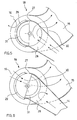
- figure 3 is a multi-level longitudinal sectional schematic view of a drying machine according to the invention in a second use configuration
- figure 4 is a multi-level cross-sectional schematic view of the drying machine from figure 3;
- f igure 5 is a sectional view of a detail of the drying machine from figures 3 and 4;
- figure 6 is a sectional view of a detail of the drying machine from figures 1 and 2;
- figure 7 is a schematic view of the control system of the drying machine from figures 1 and 2;
- figure 8 is a control diagram of the drying machine shown in figures 1 and 2.
- a laundry dryer 1 comprises a housing 2 to accommodate a laundry-collecting basket or drum 3.
- the basket 3 is provided with an inlet aperture 4 for a drying air flow 5 and an outlet aperture 6 for wet air 7.
- Said apertures are communicate with a pipeline system with ventilation means associated thereto, for example a fan wheel 8 driven by an electric motor 9, to convey the drying air flow 5, through the inlet aperture 4 to basket 3 and remove wet air 7 therefrom through the outlet aperture 6.
- suitable heating means being set in a heat-exchange relation with drying air 5, for example an electric resistance 10, arranged within the air flow 5 upstream of the inlet aperture 4 and suitable to heat the air 5 before it enters the basket 3.
- Condensing means such as a heat exchanger, are associated to said pipeline system and are suitable to dehumidify the wet air 7 removed from the basket 3.
- the laundry drying machine 1 further comprises moving means for the basket 3 such as to cause the laundry to spin and swirl while being exposed to the drying air flow 5.
- moving means for the basket 3 such as to cause the laundry to spin and swirl while being exposed to the drying air flow 5.
- These means comprise for example an electric motor (not shown) rotating the basket 3, preferably in directions which can be alternated.
- the pipeline system comprises an intake opening 11 to draw in ambient air 12 from outside the housing 1 and a release opening 13 for releasing the air in the environment and it defines, i.e. provides, inside the housing 1:
- said switching means allow to selectively operate the drying machine, either by means of said open circuit or by means of said closed circuit.
- the switching means can be adjusted such as to allow the machine to be simultaneously operated by means of said open circuit and said closed circuit, wherein the relation between the flow rates in the open circuit and in the closed circuit can be preferably adjusted and set as desired.
- the pipeline system comprises an air removal pipe 14 in fluid communication with the outlet aperture 6 of basket 3, a delivery pipe 15 in fluid communication with the inlet aperture 4 of basket 3, an intake pipe 16 in fluid communication with the intake opening 11 and a release pipe 17 in fluid communication with the release opening 13.
- the air removal pipe 14 is put in fluid communication with the delivery pipe 15 by interposing a delivery flow regulator 18, suitable to adjust the flow passage between the air removal 14 and delivery 15 pipes and the air removal pipe 14 is put in fluid communication with the release pipe 17 by interposing a release flow regulator 19, suitable to adjust the flow between the air removal 14 and release 17 pipes.
- the delivery pipe 15 is put in fluid communication with the intake pipe 16 by interposing a intake flow regulator 18 suitable to adjust the flow passage between the intake 16 and delivery 15 pipes.
- said delivery 18, intake 18 and release 19 flow regulators can be operated either independently from one another or depending on one another by suitable automatic operating means, such as one or more electric driving motors 32.
- the delivery flow regulator 18 and the intake flow regulator 18 are united in one delivery flow deflector 18, suitable to put the delivery pipe 15, in fluid connection either with the air removal pipe 14 or the intake pipe 16, as desired.
- the delivery flow deflector 18 is suitable to set up (i.e. to compose) the air flow supplied to the delivery pipe 15, by adjusting the individual flow rates of the air flows from the air removal 14 and intake 16 pipes.
- deflector (not shown in the figures), which is suitable to compose the air flow supplied to the delivery pipe 15 by adjusting the individual flow rates of the air flows from the air removal 14 and intake 16 pipes, wherein said deflector is further suitable to deflect directly to the release pipe 17 that portion of the air flow from the air removal pipe 14 which is not supplied to the delivery pipe 15.
- the condensing means are embodied by a heat exchanger 20, 21, 22 arranged along the path of the air removal pipe 14 which is preferably the housing thereof.
- the heating resistance 10 is arranged along the path of the delivery pipe 15, preferably being housed therein.
- the air removal pipe 14, made in a tubular structure, of a preferably rectangular section in plastic carrying a lint filter 33, extends from the outlet aperture 6 of basket 3 preferably towards the dryer lower portion 1, where said pipe 14 defines a condensing chamber 20 provided with a cool water tank 21 that can be supplied from the water system by means of a suitable aperture, preferably a spraying nozzle or nebulizer 22 being arranged in the wall of the air removal pipe 14 above a maximum water level 24.
- the tank 21 acts both as a container for the cold water from the water system which cools the air removed by the basket 3 thus condensing the moisture thereof, and as a condensate collection tank.
- suitable drainage means such as a pump 26 suitable to discharge preferably sequentially or intermittently either the whole or part of the liquid contained within the tank 21 in order to maintain or contain said maximum water level 24.
- a conventional air/air condenser in which a suitable fan wheel, advantageously driven by the control unit similarly to the above control of the spraying nozzle 22 and drainage pump 26, conveys a cooling air flow which cools the air removed from the basket 3 thus condensing the moisture thereof.
- the delivery commutator 18 comprises a housing 27, preferably of a cylindrical or conical shape, which is equipped with three apertures 28, 29, 30 being provided at different locations and forming the three above connections, as well as a shutter element 31, also of an at least partially cylindrical or conical shape being rotatably accommodated within the housing 27.
- the shutter element 31, according to its angular position relative to the housing 27 of the delivery commutator 18, is suitable to adjust the opening/closure, respectively, of the fluid connections (apertures 28, 29, 30) of the delivery commutator 18 to the intake 16 and air removal 14 pipes and deviate the respective air flows to the delivery pipe 15.
- the delivery pipe 15 extends from the delivery commutator 18 to the inlet aperture 4 of basket 3.
- the fan wheel 8 is arranged within that part of the delivery pipe 15 immediately adjoining the delivery commutator 18, and preferably the rotation axes of motor 9 and of fan wheel 8 coincide with the rotation axis of adjustment of the shutter 31.
- the heating resistance 10 is arranged in the delivery pipe 15 downstream of the fan wheel 8 as seen from the air flow direction.
- the intake pipe 16 being formed by a suitable plastic tube or suitable spaces provided within the housing 2 of the drying machine 1 extends from the intake opening 11 (which can be provided as a single aperture, grid, or a plurality of apertures within the housing 2) to the aperture 29 of the delivery commutator 18, thus providing the supply of cool air 12 from the external environment.
- the release pipe 17, which is formed by a suitable plastic tube or suitable spaces provided within the housing 2 of the drying machine 1 extends from a flow regulator 19 connected to the air removal pipe 14, preferably in an area thereof downstream of the condensing chamber 20, to the release opening 11 (which can be provided for example as a single aperture, grid, or a plurality of apertures within the housing 2).
- the flow regulator 19 comprises a housing, preferably of a cylindrical or conical shape, provided with two apertures forming the fluid communication between the air removal pipe 14 and the release pipe 17, as well as a shutter element, also having an at least partially cylindrical or conical shape, being rotatably accommodated within the housing.
- the shutter element according to its angular position relative to the housing of the flow regulator, is suitable to adjust the opening/closure, respectively, of the fluid connection between the air removal 14 and release 17 pipes, thus adjusting the air flow released outside the drying machine 1.
- both the delivery commutator 18 and the regulator 19 of the discharge flow can be automatically adjusted by suitable driving means, for example one or more electric regulating motors 32 to be controlled by a control unit 34 of the drying machine 1.
- suitable driving means for example one or more electric regulating motors 32 to be controlled by a control unit 34 of the drying machine 1.
- the drying machine 1 comprises sensing means 35 detecting the air moisture in the environment outside the washing tank 3.
- Said sensing means 35 comprise a moisture sensor 35 being arranged at the housing 2, preferably at the intake opening 11.
- the moisture sensor 35 preferably a digital hygrometer suitable to measure the relative moisture of the air outside the basket/tank unit 3, is connected to the control unit 34, such as a microcomputer suitable to compare the data supplied by sensor 35 with the comparative values advantageously obtained by suitable work tables or curves being stored and adapted to the various drying programs.
- the control unit 34 is in turn connected to the electric motor 32 driving the switching means 18, 19 (and, advantageously, also with the condensing means, particularly with the spraying nozzle 22) and allows to adjust the electric supply thereof based on the sensor data 35 i.e. the result of the comparison between the sensor data 35 and the comparative values stored.
- the control unit 34 can be herein either a single centralized component or a plurality of decentralized units, for example consisting of several control devices directly associated to the motor or motors 32, thereby a data processing part can be carried out in a centralized manner, whereas another data processing part is directly carried out for example by the sensor device 35 or the control circuit of motor 32.
- the control unit 34 compares a moisture value U_REL measured by sensor 35 with a reference lower threshold value LIM_INF and, in the case where the measured moisture value U_REL is lower than the lower threshold value LIM _INF, it influences, by means of motor 32, the flow regulators 18, 19 such as to release all the air 7 removed from the drying space (i.e. from the basket 3) to the external environment and draw in a corresponding amount of air from the external environment to form the drying air flow 5.
- the control unit 34 drives the flow regulators 18, 19 and the condensing means 20, 21, 22, 26 such as to extract at least a part of the moisture from the air 7 removed from basket 3 and, after at least a part of moisture has been extracted therefrom, reintroduce at least a part of the air 7 removed by the basket 3 to the drying air flow 5.
- control unit 34 further compares the measured moisture value U_REL with a reference upper threshold value LIM_SUP greater than the lower threshold value LIM_INF and, in the case where the measured moisture value U_REL is greater than the upper threshold value LIM_SUP, the control unit 34 drives the flow regulators 18, 19 and the condensing means 20, 21, 22, 26 such as to reintroduce substantially all the air 7 removed by the drying space (basket 3), after at least a part of moisture has been extracted therefrom, to the drying air flow 5.
- the amount of the air released to the external environment and the amount of the air 12 drawn in from the external environment will be reduced and the amount of the air 7 removed from the basket 3 and introduced again in the drying air flow 5 will be increased in a substantially continuous manner, preferably proportionate to the increase in the measured moisture value U_REL, as can be seen for example in the diagram shown in Figure 8.
- the extraction of moisture from the air removed from the drying space will be also increased, preferably substantially proportionate to the increase in the measured moisture value U_REL.
- the control unit 34 following the comparison between the value of the external moisture U_REL being measured by sensor 35 and the lower LIM_INF and upper LIM_SUP threshold values switches the drying machine 1, by means of the motors 32, to an open circuit operation mode, such as illustrated in Figures 1 and 2.
- the ambient air is drawn in through the intake opening 11 and conveyed by the fan wheel 8 along the intake duct 16, through the delivery commutator 18 into the delivery pipe 15, inside which the air is heated by the resistance 10 before entering the basket 3 where it causes the moisture contained in the laundry to evaporate.
- Wet air is removed by the basket 3 through the outlet aperture 6 and conveyed along the air removal pipe 14, through the flow regulator 19 open on the release pipe 17, and it is released outside the drying machine 1 through the release opening 13.
- the delivery commutator 18 prevents that the air from the air removal pipe 14 may be drawn in to the delivery pipe 15, as it can be seen for example in Figure 6.
- the control unit 34 In the case where the drying machine 1 is installed in a room with poor ventilation (U_REL > LIM_INF e U_REL > LIM_SUP) which requires the drying air to be dehumidified within the drying machine 1, the control unit 34, following the comparison between the external moisture value U_REL as measured by sensor 35 and the lower LIM_INF and upper LIM_SUP threshold values, switches the drying machine 1, by means of the motors 32, to a closed-circuit (i.e. condensing) operation, such as illustrated in Figures 3 and 4.
- a closed-circuit i.e. condensing
- the wet air removed from basket 3 through the outlet aperture 6 is drawn by the fan wheel 8, through the lint filter 33, in the air removal pipe 14, by flowing therein through the condensing chamber 20.
- Cool water drawn from the water system is supplied by the spraying nozzle 22, which is preferably provided with a solenoid valve controlled by the control unit 34, directly to the air removal pipe 14 thus forming a cold fog therein, particularly in the condensing chamber 20, and is collected in the tank 21 thus forming a cold water surface over substantially the whole widened area of the air removal pipe 14, i.e. the whole condensing chamber 20.
- wet air is cooled both by the cold fog and the cold water surface while flowing through the condensing chamber 20, and it is dehumidified by condensing the moisture.
- the condensate is collected in the tank 21 containing the cooling water and is sequentially discharged therewith out of the drying machine 1.
- the dehumidified air is conveyed from the air removal pipe 14, through the delivery commutator 18, to the delivery pipe 15, where it is heated again by resistance 10 before being resent to basket 3.
- the delivery commutator 18 prevents both that the air is drawn in from the intake pipe 16 to the delivery pipe 15 and that the air is released from the air removal pipe 14 to the release pipe 17, as can be seen for example in Figures 4 and 5.
- the control unit 34 subsequent to the comparison between the external moisture value U_REL as measured by sensor 35 and the lower LIM_INF and upper LIM_SUP threshold values switches the drying machine 1, by operating the motors 32, to a hybrid operation, in which the delivery flow drawn in the delivery pipe 15 is composed of two flows having a controlled rate, by means of the delivery commutator 18.
- a first flow consists of ambient air drawn in from outside the drying machine 1 through the intake pipe 16 and a second flow consists of recycled dehumidified air drawn in from the air removal pipe 14. The excess air in the air removal pipe 14 is released out of the drying machine through the release pipe 17.
- the filter 33 is inserted into and extends along the length 14 of the vertical flow path, and the flow path length itself at least partially defines the condensing chamber 20 and the water collection tank 21.
- a previously measured parameter for example as a function of the air moisture U_REL outside the drying space.
- control unit 34 of the drying machine is suitable to compare the data supplied by sensor 35 with comparative values advantageously obtained by suitable working tables or curves being stored and adapted to the various drying programs.
- the control unit 34 is in turn connected to the electric motor 9 driving the fan wheel 8 to adjust the power supply of said motor 9 based on the data of sensor 35, i.e. the result of the comparison of the data of sensor 35 with the comparative values stored.
- the drying method can provide the further step of changing the speed (i.e. the rate) of the drying air flow 5 as a function of the pressure or rate of this drying air flow 5 upstream of the inlet aperture 4 of basket 3, i.e. the drying space.
- the drying device comprises sensing means suitable to detect a quantity indicative of pressure or rate of air flow 5 upstream of the inlet aperture 4.
- the sensing means comprise for example a pressure sensor connected to the control unit 34 which is suitable to compare the data supplied by the pressure sensor with the comparative values, which are advantageously obtained by suitable work tables or curves being stored and adapted to the various drying programs.
- the control unit 34 is in turn connected to motor 9 of fan wheel 8 and adjusts the power supply thereof based on the data of the pressure sensor, i.e. the result of the comparison of the data of pressure sensor with the comparative data stored.
- a pressure increase upstream of the inlet aperture 4, which is indicative of a stagnation of air flow 5 due for example to the inlet aperture 4 being obstructed by a piece of laundry, can be detected and identified as such by the pressure sensor and the control unit 34, which can either increase the supply to the ventilator means 8, 9 to quickly clear the inlet aperture 4 by a high air thrust, thus actively reestablishing a high-efficiency drying condition, or reduce the supply to the ventilation means 8, 9 in order to reduce the energy consumption of the latter during the inefficient drying step, until the inlet aperture 4 is cleared, such as for example by the motion of basket 3 or the laundry weight.
- control unit 34 is advantageously suitable to reduce or cut-off the power supply to the resistance 10 until the pressure detected by the pressure sensor returns to the normal value, i.e. a value indicating a normal or high drying efficiency.
- the sensing means for measuring the rate or pressure of the drying air flow 5 are provided through the electric motor 9 of the fan wheel 8 conveying the drying air 5.
- This motor 9 is for example a brushless, induction asynchronous motor or a collector motor, the speed and torque of which vary as a function of the working point of the fan wheel 8, which depends in turn on the actual inlet aperture 4 of basket 3.
- either the number of revolutions of the fan wheel 8 or electric parameters of the motor 9 itself can be used, particularly the frequency/voltage ratio (Hz/V), as the quantity indicative of the pressure or rate of air flow 5 upstream of the inlet aperture 4.
- Hz/V frequency/voltage ratio
- the rotor rotational speed can be measured for example by means of an encoder, whereas the electric quantities can be detected by suitable sensing means being associated to the motor 9 or included in the control device of motor 9 or in the electronics of control unit 34.
- control unit 34 receives signals relative to the electric parameters detected at motor 9 and processes them similarly to what has been stated above.
- the invention can be advantageously implemented both in front-loading and top-loading drying machines and washer-dryers.
- this drying method can be implemented in a single equipment that can be adapted to said several operating types (open circuit, closed circuit, combined circuit), in which, in the open circuit operating mode, the dehumidifying means 20, 21, 24, 25, 26, i.e. the condensing system is normally deactivated but it may also be activated, for example in a controlled manner by means of the dryer control unit 34, in order to reduce the moisture load in the air released in the environment in a controlled manner.
- the dehumidifying means 20, 21, 24, 25, 26, i.e. the condensing system is normally deactivated but it may also be activated, for example in a controlled manner by means of the dryer control unit 34, in order to reduce the moisture load in the air released in the environment in a controlled manner.
- the laundry drying machine has a very simple and solid structure, in which the closed circuit 14, 15 forms a portion of open circuit 14, 15, 16, 17, i.e. both circuits have the delivery pipe 14 and the air removal pipe 14 in common. This makes manufacture and maintenance of the appliance easier and cost-effective.
- the drying machine Due to the commutability between the open drying and closed condensing configurations, and the control of respective air flows as a function of the external air moisture, the drying machine can be easily and automatically adapted to various installation rooms (as well as environmental condition changes even occurring in the course of a drying operation) and provides a high drying performance, by fully exploiting the moisture-disposal capacity of the installation environment.
Abstract
- conveying a drying air flow (5) to the drying space (3) such that said drying air (5) skims the laundry to be dried to extract at least a part of moisture therefrom;
- removing wet air (7) from the drying space (3);
- measuring the moisture (U_REL) of air in the external environment;
- adjusting, as a function of the measured moisture (U_REL), the rate of a recirculated air flow consisting of at least a part of the air (7) removed from the drying space (3) and reintroducing said recirculated air flow, after it has been at least partially dehumidified, to the drying air flow (5) and a corresponding laundry drying machine.
Description
- The present invention relates to a method for drying laundry as well as a drying device of the drying machine or washer-dryer types, which dries the laundry by means of an air flow.
- The drying circuit of these drying devices typically comprises a drying space separate from the external environment, such as a basket/tank unit, an intake unit, a heat exchanger and a heating unit with electric resistances.
- In a drying circuit known as the closed circuit, the air flow supplied by the intake unit is heated by the electric resistances and conveyed to the basket or drum, where, by flowing through the wet laundry, it causes the water contained in the fabrics to evaporate. In the heat exchanger, generally of the atmospheric type, wet air is cooled either by a cold water flow or a cool air flow. Due to the cooling, the vapour condensates and is collected and released together with the cooling water. The de-humidified air is then drawn in by the intake unit and caused to recirculate.
- On the other hand, in the case of a drying circuit known as the open circuit, the drying air is drawn in from the environment and, after flowing through the laundry, thus absorbing the moisture thereof, it is directly released to the environment.
- The closed-circuit drying devices have a high energy consumption and offer a low-medium drying performance. The open-circuit drying devices, though having a lower energy consumption and offering a better drying performance than those with closed-circuit, can be operated only in rooms provided with a sufficient ventilation, and most of them require a forced ventilation.
- Drying machines for domestic use are also known which have an open-circuit base appliance having intake and release ports to which a separate optional device can be coupled from the outside to convert the drying machine into a closed-circuit condensing device.
- Both the condensing and the convertible drying machines are structurally complex and expensive, and the convertible devices allow the open-to-closed conversion of the system to be performed only before installation, for example in a laundry, because this conversion entails changing the size of the drying machine.
- A further drawback of the prior art drying machines lies in that they are designed for unchanged environmental conditions, whereas ventilation, temperature, and moisture in the room where a drying machine is typically installed are actually variable, both in the course of a day and over one year, and further they strongly depend on the inhabitants' habits of heating and ventilation.
- Accordingly, drying machines almost never operate in the exact conditions they have been designed for, and therefore they offer a non-optimum overall energy performance.
- Therefore, the object of the present invention is to provide a drying method to be implemented in a drying device having such characteristics as to improve the overall energy performance and allow the drying device to be operated in variable environmental conditions.
- This and other objects are achieved by means of a method for drying wet laundry contained in a drying space at least partially isolated from an external environment, the method comprising the steps below:
- conveying a drying air flow to the drying space such that said drying air skims the laundry to be dried in order to extract at least part of the moisture therefrom;
- removing wet air from the drying space;
- measuring the air moisture in the external environment;
- adjusting, as a function of the measured moisture, the flow rate of a recirculated air flow consisting of at least a part of the air removed from the drying space and reintroducing said recirculated air flow, after it has been at least partially de-humidified, to the drying air flow, particularly,
- comparing the measured moisture value with a reference lower threshold value, and
- in the case where the measured moisture value is lower than the lower threshold value,
- releasing all the air removed from the drying space to the external environment and drawing in a corresponding amount of air from the external environment to form the drying air flow, and
- in the case where the measured moisture value is higher than the lower threshold value,
- extracting at least part of the moisture from the air removed from the drying space and
- reintroducing at least part of the air removed from the drying space, after at least part of the moisture has been extracted therefrom, to the drying air flow.
- The method according to the invention can be carried out by means of a laundry-drying device according to
claim 9. - In order to better understand the invention and appreciate the advantages thereof, some embodiments thereof will be described herein below by way of nonlimiting examples with reference to the annexed figures, in which:
- figure 1 is a multi-level longitudinal sectional schematic view of a drying machine according to the invention in a first use configuration;
- figure 2 is a multi-level cross-sectional schematic view of the drying machine from figure 1;
- figure 3 is a multi-level longitudinal sectional schematic view of a drying machine according to the invention in a second use configuration;
- figure 4 is a multi-level cross-sectional schematic view of the drying machine from figure 3;
-
f igure 5 is a sectional view of a detail of the drying machine from figures 3 and 4; - figure 6 is a sectional view of a detail of the drying machine from figures 1 and 2;
- figure 7 is a schematic view of the control system of the drying machine from figures 1 and 2;
- figure 8 is a control diagram of the drying machine shown in figures 1 and 2.
- With reference to figures 1 to 7, a
laundry dryer 1 comprises ahousing 2 to accommodate a laundry-collecting basket ordrum 3. Thebasket 3 is provided with aninlet aperture 4 for adrying air flow 5 and anoutlet aperture 6 forwet air 7. Said apertures are communicate with a pipeline system with ventilation means associated thereto, for example afan wheel 8 driven by anelectric motor 9, to convey thedrying air flow 5, through theinlet aperture 4 tobasket 3 and removewet air 7 therefrom through theoutlet aperture 6. - There are also provided suitable heating means being set in a heat-exchange relation with drying
air 5, for example anelectric resistance 10, arranged within theair flow 5 upstream of theinlet aperture 4 and suitable to heat theair 5 before it enters thebasket 3. - Condensing means, such as a heat exchanger, are associated to said pipeline system and are suitable to dehumidify the
wet air 7 removed from thebasket 3. - Advantageously, the
laundry drying machine 1 further comprises moving means for thebasket 3 such as to cause the laundry to spin and swirl while being exposed to the dryingair flow 5. These means comprise for example an electric motor (not shown) rotating thebasket 3, preferably in directions which can be alternated. - The pipeline system comprises an
intake opening 11 to draw inambient air 12 from outside thehousing 1 and a release opening 13 for releasing the air in the environment and it defines, i.e. provides, inside the housing 1: - an
open circuit basket 3 and remove it therefrom to be released again to the environment, and the heating means 10 to heat the air drawn in before it enters the basket 3 (open circuit) and - a closed
circuit basket 3 and remove it therefrom to be conveyed again to thebasket 3, the heating means 10 to heat the air before it enters thebasket 3 and the condensing means 20, 21, 22 to dehumidify the air before it is heated (closed circuit), wherein switching means 18, 19 are provided to selectively convert said pipeline system to said first and second circuits. - In accordance with an embodiment, said switching means allow to selectively operate the drying machine, either by means of said open circuit or by means of said closed circuit.
- In accordance with a further embodiment, the switching means can be adjusted such as to allow the machine to be simultaneously operated by means of said open circuit and said closed circuit, wherein the relation between the flow rates in the open circuit and in the closed circuit can be preferably adjusted and set as desired.
- The pipeline system comprises an
air removal pipe 14 in fluid communication with theoutlet aperture 6 ofbasket 3, adelivery pipe 15 in fluid communication with theinlet aperture 4 ofbasket 3, anintake pipe 16 in fluid communication with theintake opening 11 and arelease pipe 17 in fluid communication with the release opening 13. - In accordance with an embodiment of the invention, the
air removal pipe 14 is put in fluid communication with thedelivery pipe 15 by interposing adelivery flow regulator 18, suitable to adjust the flow passage between theair removal 14 anddelivery 15 pipes and theair removal pipe 14 is put in fluid communication with therelease pipe 17 by interposing arelease flow regulator 19, suitable to adjust the flow between theair removal 14 and release 17 pipes. On the other hand, thedelivery pipe 15 is put in fluid communication with theintake pipe 16 by interposing aintake flow regulator 18 suitable to adjust the flow passage between theintake 16 and delivery 15 pipes. - In accordance with an embodiment of the invention, said
delivery 18,intake 18 and release 19 flow regulators can be operated either independently from one another or depending on one another by suitable automatic operating means, such as one or moreelectric driving motors 32. - In accordance with the embodiment shown in the figures, the
delivery flow regulator 18 and theintake flow regulator 18 are united in onedelivery flow deflector 18, suitable to put thedelivery pipe 15, in fluid connection either with theair removal pipe 14 or theintake pipe 16, as desired. - Advantageously, the
delivery flow deflector 18 is suitable to set up (i.e. to compose) the air flow supplied to thedelivery pipe 15, by adjusting the individual flow rates of the air flows from theair removal 14 and intake 16 pipes. - In accordance with a further embodiment of the invention, there is provided only one deflector (not shown in the figures), which is suitable to compose the air flow supplied to the
delivery pipe 15 by adjusting the individual flow rates of the air flows from theair removal 14 and intake 16 pipes, wherein said deflector is further suitable to deflect directly to therelease pipe 17 that portion of the air flow from theair removal pipe 14 which is not supplied to thedelivery pipe 15. - Advantageously, the condensing means are embodied by a
heat exchanger air removal pipe 14 which is preferably the housing thereof. - On the other hand, the
heating resistance 10 is arranged along the path of thedelivery pipe 15, preferably being housed therein. - According to an embodiment, the
air removal pipe 14, made in a tubular structure, of a preferably rectangular section in plastic carrying alint filter 33, extends from theoutlet aperture 6 ofbasket 3 preferably towards the dryerlower portion 1, where saidpipe 14 defines acondensing chamber 20 provided with acool water tank 21 that can be supplied from the water system by means of a suitable aperture, preferably a spraying nozzle ornebulizer 22 being arranged in the wall of theair removal pipe 14 above amaximum water level 24. Thetank 21 acts both as a container for the cold water from the water system which cools the air removed by thebasket 3 thus condensing the moisture thereof, and as a condensate collection tank. - At the lowermost point of the
tank 21 there is provided anoutlet 25 associated to suitable drainage means, such as apump 26 suitable to discharge preferably sequentially or intermittently either the whole or part of the liquid contained within thetank 21 in order to maintain or contain saidmaximum water level 24. - Alternatively, there can be provided a conventional air/air condenser, in which a suitable fan wheel, advantageously driven by the control unit similarly to the above control of the spraying
nozzle 22 anddrainage pump 26, conveys a cooling air flow which cools the air removed from thebasket 3 thus condensing the moisture thereof. - The
air removal pipe 14, particularly a portion thereof located downstream of thecondensing chamber 20, as seen in the air flow direction, opens into saiddelivery commutator 18 which comprises, besides the fluid connection to theair removal pipe 14, a fluid connection to thedelivery pipe 15 and one to theintake pipe 16, - Advantageously, the
delivery commutator 18 comprises ahousing 27, preferably of a cylindrical or conical shape, which is equipped with threeapertures shutter element 31, also of an at least partially cylindrical or conical shape being rotatably accommodated within thehousing 27. - The
shutter element 31, according to its angular position relative to thehousing 27 of thedelivery commutator 18, is suitable to adjust the opening/closure, respectively, of the fluid connections (apertures delivery commutator 18 to theintake 16 andair removal 14 pipes and deviate the respective air flows to thedelivery pipe 15. - The
delivery pipe 15 extends from thedelivery commutator 18 to theinlet aperture 4 ofbasket 3. - Advantageously, the
fan wheel 8 is arranged within that part of thedelivery pipe 15 immediately adjoining thedelivery commutator 18, and preferably the rotation axes ofmotor 9 and offan wheel 8 coincide with the rotation axis of adjustment of theshutter 31. - The
heating resistance 10 is arranged in thedelivery pipe 15 downstream of thefan wheel 8 as seen from the air flow direction. - The
intake pipe 16, being formed by a suitable plastic tube or suitable spaces provided within thehousing 2 of the dryingmachine 1 extends from the intake opening 11 (which can be provided as a single aperture, grid, or a plurality of apertures within the housing 2) to theaperture 29 of thedelivery commutator 18, thus providing the supply ofcool air 12 from the external environment. - The
release pipe 17, which is formed by a suitable plastic tube or suitable spaces provided within thehousing 2 of the dryingmachine 1 extends from aflow regulator 19 connected to theair removal pipe 14, preferably in an area thereof downstream of the condensingchamber 20, to the release opening 11 (which can be provided for example as a single aperture, grid, or a plurality of apertures within the housing 2). - Advantageously, the
flow regulator 19 comprises a housing, preferably of a cylindrical or conical shape, provided with two apertures forming the fluid communication between theair removal pipe 14 and therelease pipe 17, as well as a shutter element, also having an at least partially cylindrical or conical shape, being rotatably accommodated within the housing. - The shutter element, according to its angular position relative to the housing of the flow regulator, is suitable to adjust the opening/closure, respectively, of the fluid connection between the
air removal 14 and release 17 pipes, thus adjusting the air flow released outside the dryingmachine 1. - According to an embodiment, both the
delivery commutator 18 and theregulator 19 of the discharge flow can be automatically adjusted by suitable driving means, for example one or moreelectric regulating motors 32 to be controlled by acontrol unit 34 of the dryingmachine 1. - Advantageously, the drying
machine 1 comprises sensing means 35 detecting the air moisture in the environment outside thewashing tank 3. Said sensing means 35 comprise amoisture sensor 35 being arranged at thehousing 2, preferably at theintake opening 11. Themoisture sensor 35, preferably a digital hygrometer suitable to measure the relative moisture of the air outside the basket/tank unit 3, is connected to thecontrol unit 34, such as a microcomputer suitable to compare the data supplied bysensor 35 with the comparative values advantageously obtained by suitable work tables or curves being stored and adapted to the various drying programs. Thecontrol unit 34 is in turn connected to theelectric motor 32 driving the switching means 18, 19 (and, advantageously, also with the condensing means, particularly with the spraying nozzle 22) and allows to adjust the electric supply thereof based on thesensor data 35 i.e. the result of the comparison between thesensor data 35 and the comparative values stored. - The
control unit 34 can be herein either a single centralized component or a plurality of decentralized units, for example consisting of several control devices directly associated to the motor ormotors 32, thereby a data processing part can be carried out in a centralized manner, whereas another data processing part is directly carried out for example by thesensor device 35 or the control circuit ofmotor 32. - The
control unit 34 compares a moisture value U_REL measured bysensor 35 with a reference lower threshold value LIM_INF and, in the case where the measured moisture value U_REL is lower than the lower threshold value LIM _INF, it influences, by means ofmotor 32, theflow regulators air 7 removed from the drying space (i.e. from the basket 3) to the external environment and draw in a corresponding amount of air from the external environment to form the dryingair flow 5. - In the case where the measured moisture value U_REL is greater than the lower threshold value LIM_INF, the
control unit 34 drives theflow regulators air 7 removed frombasket 3 and, after at least a part of moisture has been extracted therefrom, reintroduce at least a part of theair 7 removed by thebasket 3 to the dryingair flow 5. - Advantageously, the
control unit 34 further compares the measured moisture value U_REL with a reference upper threshold value LIM_SUP greater than the lower threshold value LIM_INF and, in the case where the measured moisture value U_REL is greater than the upper threshold value LIM_SUP, thecontrol unit 34 drives theflow regulators air 7 removed by the drying space (basket 3), after at least a part of moisture has been extracted therefrom, to the dryingair flow 5. - In accordance with an embodiment, when the measured moisture U_REL ranges between the lower threshold value LIM_INF and the upper threshold value LIM_SUP, the amount of the air released to the external environment and the amount of the
air 12 drawn in from the external environment will be reduced and the amount of theair 7 removed from thebasket 3 and introduced again in the dryingair flow 5 will be increased in a substantially continuous manner, preferably proportionate to the increase in the measured moisture value U_REL, as can be seen for example in the diagram shown in Figure 8. - Advantageously, in the case where said measured moisture value U_REL ranges between the lower threshold value LIM_INF and the upper threshold value LIM_SUP, the extraction of moisture from the air removed from the drying space will be also increased, preferably substantially proportionate to the increase in the measured moisture value U_REL.
- The operation of the
dryer 1 according to the invention is described below. - In the case where the drying
machine 1 is installed in a well ventilated room (U_REL < LIM_INF e U_REL < LIM_SUP) which allows the vapour to be released from the dryingmachine 1, thecontrol unit 34, following the comparison between the value of the external moisture U_REL being measured bysensor 35 and the lower LIM_INF and upper LIM_SUP threshold values switches the dryingmachine 1, by means of themotors 32, to an open circuit operation mode, such as illustrated in Figures 1 and 2. - The ambient air is drawn in through the
intake opening 11 and conveyed by thefan wheel 8 along theintake duct 16, through thedelivery commutator 18 into thedelivery pipe 15, inside which the air is heated by theresistance 10 before entering thebasket 3 where it causes the moisture contained in the laundry to evaporate. Wet air is removed by thebasket 3 through theoutlet aperture 6 and conveyed along theair removal pipe 14, through theflow regulator 19 open on therelease pipe 17, and it is released outside the dryingmachine 1 through therelease opening 13. - In this construction, the
delivery commutator 18 prevents that the air from theair removal pipe 14 may be drawn in to thedelivery pipe 15, as it can be seen for example in Figure 6. - In the case where the drying
machine 1 is installed in a room with poor ventilation (U_REL > LIM_INF e U_REL > LIM_SUP) which requires the drying air to be dehumidified within the dryingmachine 1, thecontrol unit 34, following the comparison between the external moisture value U_REL as measured bysensor 35 and the lower LIM_INF and upper LIM_SUP threshold values, switches the dryingmachine 1, by means of themotors 32, to a closed-circuit (i.e. condensing) operation, such as illustrated in Figures 3 and 4. - The wet air removed from
basket 3 through theoutlet aperture 6 is drawn by thefan wheel 8, through thelint filter 33, in theair removal pipe 14, by flowing therein through the condensingchamber 20. - Cool water drawn from the water system is supplied by the spraying
nozzle 22, which is preferably provided with a solenoid valve controlled by thecontrol unit 34, directly to theair removal pipe 14 thus forming a cold fog therein, particularly in the condensingchamber 20, and is collected in thetank 21 thus forming a cold water surface over substantially the whole widened area of theair removal pipe 14, i.e. the whole condensingchamber 20. - Wet air, is cooled both by the cold fog and the cold water surface while flowing through the condensing
chamber 20, and it is dehumidified by condensing the moisture. The condensate is collected in thetank 21 containing the cooling water and is sequentially discharged therewith out of the dryingmachine 1. - The dehumidified air is conveyed from the
air removal pipe 14, through thedelivery commutator 18, to thedelivery pipe 15, where it is heated again byresistance 10 before being resent tobasket 3. - In this configuration, the
delivery commutator 18 prevents both that the air is drawn in from theintake pipe 16 to thedelivery pipe 15 and that the air is released from theair removal pipe 14 to therelease pipe 17, as can be seen for example in Figures 4 and 5. - In the case where the drying device installation room is provided with such a ventilation allowing to drain a vapour amount sufficient for drying but not sufficient for operating an open circuit drying machine (U_REL > LIM_INF e U_REL < LIM_SUP), the
control unit 34, subsequent to the comparison between the external moisture value U_REL as measured bysensor 35 and the lower LIM_INF and upper LIM_SUP threshold values switches the dryingmachine 1, by operating themotors 32, to a hybrid operation, in which the delivery flow drawn in thedelivery pipe 15 is composed of two flows having a controlled rate, by means of thedelivery commutator 18. A first flow consists of ambient air drawn in from outside the dryingmachine 1 through theintake pipe 16 and a second flow consists of recycled dehumidified air drawn in from theair removal pipe 14. The excess air in theair removal pipe 14 is released out of the drying machine through therelease pipe 17. - In accordance with an embodiment, the
filter 33 is inserted into and extends along thelength 14 of the vertical flow path, and the flow path length itself at least partially defines the condensingchamber 20 and thewater collection tank 21. - In accordance with a particularly advantageous development of the inventive drying method, there is provided the step of varying the rate of the drying
air flow 5, preferably as a function of a previously measured parameter, for example as a function of the air moisture U_REL outside the drying space. Advantageously, this allows to compensate for a poor capacity of absorbing the air moisture (which can be identified through a high relative moisture value, i.e. air saturation degree) by increasing the rate of the dryingair flow 5 and, accordingly, by increasing the volume of air skimming the laundry to be dried. - To the purpose, the
control unit 34 of the drying machine is suitable to compare the data supplied bysensor 35 with comparative values advantageously obtained by suitable working tables or curves being stored and adapted to the various drying programs. Thecontrol unit 34 is in turn connected to theelectric motor 9 driving thefan wheel 8 to adjust the power supply of saidmotor 9 based on the data ofsensor 35, i.e. the result of the comparison of the data ofsensor 35 with the comparative values stored. - Alternatively or in addition to changing the rate of drying air flow as a function of the external moisture, the drying method can provide the further step of changing the speed (i.e. the rate) of the drying
air flow 5 as a function of the pressure or rate of this dryingair flow 5 upstream of theinlet aperture 4 ofbasket 3, i.e. the drying space. - To the purpose, the drying device comprises sensing means suitable to detect a quantity indicative of pressure or rate of
air flow 5 upstream of theinlet aperture 4. - The sensing means comprise for example a pressure sensor connected to the
control unit 34 which is suitable to compare the data supplied by the pressure sensor with the comparative values, which are advantageously obtained by suitable work tables or curves being stored and adapted to the various drying programs. Thecontrol unit 34 is in turn connected tomotor 9 offan wheel 8 and adjusts the power supply thereof based on the data of the pressure sensor, i.e. the result of the comparison of the data of pressure sensor with the comparative data stored. - For example, a pressure increase upstream of the
inlet aperture 4, which is indicative of a stagnation ofair flow 5 due for example to theinlet aperture 4 being obstructed by a piece of laundry, can be detected and identified as such by the pressure sensor and thecontrol unit 34, which can either increase the supply to the ventilator means 8, 9 to quickly clear theinlet aperture 4 by a high air thrust, thus actively reestablishing a high-efficiency drying condition, or reduce the supply to the ventilation means 8, 9 in order to reduce the energy consumption of the latter during the inefficient drying step, until theinlet aperture 4 is cleared, such as for example by the motion ofbasket 3 or the laundry weight. - In accordance with a further embodiment of the invention, the
control unit 34 is advantageously suitable to reduce or cut-off the power supply to theresistance 10 until the pressure detected by the pressure sensor returns to the normal value, i.e. a value indicating a normal or high drying efficiency. - In accordance with an advantageous embodiment, such as illustrated in the figures, the sensing means for measuring the rate or pressure of the drying
air flow 5 are provided through theelectric motor 9 of thefan wheel 8 conveying the dryingair 5. Thismotor 9 is for example a brushless, induction asynchronous motor or a collector motor, the speed and torque of which vary as a function of the working point of thefan wheel 8, which depends in turn on theactual inlet aperture 4 ofbasket 3. - By knowing that, when the
aperture 4 is obstructed, the pressure upstream of theaperture 4 will be increased and the air rate will be decreased, and hence the number of motor revolutions will be increased whereas its torque will be decreased, either the number of revolutions of thefan wheel 8 or electric parameters of themotor 9 itself can be used, particularly the frequency/voltage ratio (Hz/V), as the quantity indicative of the pressure or rate ofair flow 5 upstream of theinlet aperture 4. - The rotor rotational speed can be measured for example by means of an encoder, whereas the electric quantities can be detected by suitable sensing means being associated to the
motor 9 or included in the control device ofmotor 9 or in the electronics ofcontrol unit 34. - Consequently, the
control unit 34 receives signals relative to the electric parameters detected atmotor 9 and processes them similarly to what has been stated above. - The invention can be advantageously implemented both in front-loading and top-loading drying machines and washer-dryers.
- The invention entails considerable advantages. First of all, this drying method can be implemented in a single equipment that can be adapted to said several operating types (open circuit, closed circuit, combined circuit), in which, in the open circuit operating mode, the dehumidifying means 20, 21, 24, 25, 26, i.e. the condensing system is normally deactivated but it may also be activated, for example in a controlled manner by means of the
dryer control unit 34, in order to reduce the moisture load in the air released in the environment in a controlled manner. - The laundry drying machine has a very simple and solid structure, in which the closed
circuit open circuit delivery pipe 14 and theair removal pipe 14 in common. This makes manufacture and maintenance of the appliance easier and cost-effective. - Due to the commutability between the open drying and closed condensing configurations, and the control of respective air flows as a function of the external air moisture, the drying machine can be easily and automatically adapted to various installation rooms (as well as environmental condition changes even occurring in the course of a drying operation) and provides a high drying performance, by fully exploiting the moisture-disposal capacity of the installation environment.
- With this invention, it is thus possible to save resources (both of material and energy) both in the manufacturing step and while using the appliance.
- Obviously, to the drying method and laundry drying machine according to the present invention, aiming at satisfying contingent and specific needs, those skilled in the art will be able to carry out further modifications and variants, all of them being contemplated within the scope of protection of the invention, such as defined in the claims below.
Claims (17)
- A method for drying wet laundry contained in a drying space (3) being at least partially isolated from an external environment, comprising the steps of:conveying a drying air flow (5) into the drying space (3) such that said drying air (5) skims the laundry to be dried to extract at least a part of its moisture ;removing wet air (7) from the drying space (3);measuring the moisture (U_REL) of the air in the external environment;adjusting, as a function of the measured moisture (U_REL), the rate of a recirculated air flow consisting of at least a part of the air (7) removed from the drying space (3) and reintroduce said recirculated air flow, after it has been at least partially dehumidified, to the drying air flow (5).
- The method according to claim 1, comprising the steps of:comparing the measured moisture value (U_REL) with a reference lower threshold value (LIM_INF) and in the case where the measured moisture value (U_REL) is lower than the lower threshold value (LIM_INF),releasing all the air (7) removed from the drying space (3) to the external environment and drawing in a corresponding amount of air (12) from the external environment to constitute the drying air flow (5) and in the case where the measured moisture value (U_REL) is higher than the lower threshold value (LIM_INF),extracting at least a part of the moisture from the air (7) removed from the drying space (3), andreintroducing at least a part of the air (7) removed from the drying space (3), after at least a part of the moisture has been extracted therefrom, to the drying air flow (5).
- The method according to claims 1 or 2, comprising the steps of:comparing the measured moisture value (U_REL) to a reference upper threshold value (LIM_SUP), which upper threshold value (LIM_SUP) is higher than the lower threshold value (LIM_INF), and
in the case where the measured moisture value (U_REL) is higher than the upper moisture value (LIM_SUP),reintroducing substantially all the air (7) removed from the drying space (3), after at least a part of moisture has been extracted therefrom, to the drying air flow (5). - The method according to any one of the preceding claims, wherein in the case where said measured moisture value (U_REL) ranges between the lower threshold value (LIM_INF) and the upper threshold value (LIM_SUP),the amount of air released to the external environment and the amount of air (12) drawn in from the external environment are reduced andthe amount of air (7) removed from the drying space (3) and reintroduced to the drying air flow (5) is increased upon the increase in the measured moisture value (U_REL).
- The method according to any one of the preceding claims, wherein in the case where said measured moisture value (U_REL) ranges between the lower threshold value (LIM_INF) and the upper threshold value (LIM_SUP), the extraction of moisture from the air (7) removed from the drying space (3) is increased upon the increase in the measured moisture value (U_REL).
- The method according to any one of the preceding claims, wherein in the case where said measured moisture value (U_REL) ranges between the lower threshold value (LIM_INF) and the upper threshold value (LIM_SUP),the amount of air released to the external environment and the amount of air (12) drawn in from the external environment are reduced andthe amount of air (7) removed from the drying space (3) and reintroduced to the drying air flow (5) is increased substantially proportionate to the increase in the measured moisture value (U_REL).
- The method according to any one of the preceding claims, wherein, in the case where said measured moisture value (U_REL) ranges between the lower threshold value (LIM_INF) and the upper threshold value (LIM_SUP), the extraction of moisture from the air (7) removed from the drying space (3) is increased substantially proportionate to the increase in the measured moisture value (U_REL).
- The method according to any one of the preceding claims, comprising the step of heating the drying air (5) before it enters the drying space (3).
- The method according to any one of the preceding claims, comprising the step of changing the rate or speed of the drying air flow (5) as a function of the measured moisture (U_REL).
- The method according to any one of the preceding claims, comprising the steps of:measuring a parameter indicative of the rate or speed of the drying air flow (5) upstream of the inlet (4) of said drying air flow (5) into the drying space (3);changing the rate or speed of the drying air flow (5) as a function of the pressure or rate of the drying air flow (5).
- The method according to any one of the preceding claims, comprising the step of heating the drying air (5) before it enters the drying space (3) in a controlled manner, by adjusting said heating of the drying air (5) as a function of the pressure or rate of the drying air flow (5) and/or moisture (U_REL) outside the drying space .
- A laundry drying machine (1) defining a drying space (3) at least partially isolated from an external environment and comprising:means (15, 8, 9) to convey a drying air flow (5) into the drying space (3) such that said drying air (5) skims the laundry to be dried in order to extract at least a part of moisture therefrom;means (14, 8, 9) to remove wet air (7) from the drying space (3);means (35) to measure the moisture (U_REL) of the air in the external environment;means (34, 32, 18, 19) suitable to adjust, as a function of the measured moisture (U_REL), the rate of a recirculated air flow consisting of at least a part of the air (7) removed from the drying space (3);means (20, 21, 22) to at least partially dehumidify said recirculated air flow;means (15, 20, 8, 9) to reintroduce said recirculated air flow, after it has been at least partially dehumidified, to the drying air flow (5).
- The laundry drying machine (1) according to claim 12, comprising a support and housing structure (2) carrying a basket or drum (3) to accommodate the laundry, said basket (3) being in communication with a pipeline system (14, 15, 16, 17) with ventilator means (8, 9) being associated thereto to convey a drying air flow (5) into the basket (3) and remove the wet air (7) from the latter, heating means (10) set in a heat-exchange relation with the drying air (5), condensing means (20, 21, 22) suitable to dehumidify the wet air (7) removed from basket (3), wherein there are provided switching means (18, 19) suitable to selectively convert said pipeline system (14, 15, 16, 17) at least between:an open circuit (16, 15, 14, 17) allowing the ventilation means (8, 9) to draw in the air from the environment, convey it to the basket (3) and remove it therefrom to release it again to the environment, and the heating means (10) to heat the air drawn in before it enters the basket 3, anda closed circuit (15, 16) allowing the ventilation means (8, 9) to convey the air to the basket (3) and remove it therefrom to convey it again to the basket (3), the heating means (10) to heat the air before it enters the basket (3) and the condensing means (20, 21, 22) to dehumidify the air before it is heated, wherein there are provided command and control means (32, 34, 35) suitable to automatically adjust said switching means (18, 19) as a function of the air moisture (U_REL) outside the basket (3).
- The laundry drying machine (1) according to claim 12 or 13, comprising means for adjusting the rate or speed of the drying air flow (5) as a function of the moisture (U_REL) of the air outside the basket (3).
- The laundry drying machine (1) according to one of claims 12 to 14, comprising means for adjusting the rate or speed of the drying air flow (5) as a function of the pressure or rate of the drying air flow (5) upstream the inlet aperture (4) of basket (3).
- The laundry drying machine (1) according to any claim 12 to 15, comprising sensing means (8, 9) suitable to measure a quantity indicative of the pressure or rate of the air flow (5) upstream of the inlet aperture (4) of basket (3), said sensing means (8, 9) being connected to said control unit (34) suitable to affect, as a function of said measured quantity, the rate of the drying air flow (5) being provided by ventilation means (8, 9) and/or the heating power of the heating means (10).
- The laundry drying machine (1) according to any claim 12 to 16, being a washer-dryer, a drying machine or a drying wardrobe.
Priority Applications (1)
| Application Number | Priority Date | Filing Date | Title |
|---|---|---|---|
| EP04017167A EP1559829B1 (en) | 2004-01-28 | 2004-07-21 | Drying method and device |
Applications Claiming Priority (3)
| Application Number | Priority Date | Filing Date | Title |
|---|---|---|---|
| EP04425051 | 2004-01-28 | ||
| EP04425051.2A EP1559828B1 (en) | 2004-01-28 | 2004-01-28 | Improved laundry drying device |
| EP04017167A EP1559829B1 (en) | 2004-01-28 | 2004-07-21 | Drying method and device |
Publications (2)
| Publication Number | Publication Date |
|---|---|
| EP1559829A1 true EP1559829A1 (en) | 2005-08-03 |
| EP1559829B1 EP1559829B1 (en) | 2007-12-26 |
Family
ID=34639513
Family Applications (2)
| Application Number | Title | Priority Date | Filing Date |
|---|---|---|---|
| EP04425051.2A Expired - Fee Related EP1559828B1 (en) | 2004-01-28 | 2004-01-28 | Improved laundry drying device |
| EP04017167A Expired - Fee Related EP1559829B1 (en) | 2004-01-28 | 2004-07-21 | Drying method and device |
Family Applications Before (1)
| Application Number | Title | Priority Date | Filing Date |
|---|---|---|---|
| EP04425051.2A Expired - Fee Related EP1559828B1 (en) | 2004-01-28 | 2004-01-28 | Improved laundry drying device |
Country Status (2)
| Country | Link |
|---|---|
| EP (2) | EP1559828B1 (en) |
| DE (1) | DE602004010877T2 (en) |
Cited By (7)
| Publication number | Priority date | Publication date | Assignee | Title |
|---|---|---|---|---|
| EP1688532A2 (en) | 2005-01-12 | 2006-08-09 | Whirlpool Corporation | Automatic clothes dryer |
| WO2007113081A1 (en) * | 2006-04-06 | 2007-10-11 | BSH Bosch und Siemens Hausgeräte GmbH | Domestic appliance for treating items of laundry |
| EP1970483A1 (en) * | 2007-03-15 | 2008-09-17 | Sanyo Electric Co., Ltd. | Washing and drying machine |
| EP2103730A1 (en) * | 2008-03-14 | 2009-09-23 | BSH Bosch und Siemens Hausgeräte GmbH | Exhaust air dryer with recirculation component and method for its operation |
| US20150059413A1 (en) * | 2013-09-03 | 2015-03-05 | Lg Electronics Inc. | Laundry treatment apparatus |
| GB2519185A (en) * | 2014-05-30 | 2015-04-15 | Dbk David & Baader Gmbh | Improvements in and relating to tumble dryers |
| CN114182510A (en) * | 2021-12-31 | 2022-03-15 | 广东美的白色家电技术创新中心有限公司 | Clothes dryer control method and device, clothes dryer and storage medium |
Families Citing this family (1)
| Publication number | Priority date | Publication date | Assignee | Title |
|---|---|---|---|---|
| DE102008043176B4 (en) * | 2008-10-24 | 2021-08-26 | BSH Hausgeräte GmbH | Dryer with heat pump, method for its operation and method for air conditioning a room |
Citations (6)
| Publication number | Priority date | Publication date | Assignee | Title |
|---|---|---|---|---|
| JPS59228897A (en) * | 1983-06-10 | 1984-12-22 | 松下電器産業株式会社 | Clothing dryer |
| US4549362A (en) * | 1982-01-19 | 1985-10-29 | Haried John C | Programmable air recirculator/mixer for a fabric dryer |
| JPH03254797A (en) * | 1990-03-02 | 1991-11-13 | Hitachi Ltd | Clothing drier |
| EP0503586A1 (en) * | 1991-03-12 | 1992-09-16 | Zanussi Elettrodomestici S.p.A. | Improvement in clothes drying machines |
| JP2000005493A (en) * | 1998-06-19 | 2000-01-11 | Hitachi Ltd | Drying operation controller in dryer for clothing |
| JP2002282595A (en) * | 2001-03-26 | 2002-10-02 | Toto Ltd | Clothes dryer |
Family Cites Families (1)
| Publication number | Priority date | Publication date | Assignee | Title |
|---|---|---|---|---|
| FR2648484A1 (en) * | 1989-06-16 | 1990-12-21 | Ciapem | Laundry drier with deferred rejection of moisture |
-
2004
- 2004-01-28 EP EP04425051.2A patent/EP1559828B1/en not_active Expired - Fee Related
- 2004-07-21 EP EP04017167A patent/EP1559829B1/en not_active Expired - Fee Related
- 2004-07-21 DE DE602004010877T patent/DE602004010877T2/en active Active
Patent Citations (6)
| Publication number | Priority date | Publication date | Assignee | Title |
|---|---|---|---|---|
| US4549362A (en) * | 1982-01-19 | 1985-10-29 | Haried John C | Programmable air recirculator/mixer for a fabric dryer |
| JPS59228897A (en) * | 1983-06-10 | 1984-12-22 | 松下電器産業株式会社 | Clothing dryer |
| JPH03254797A (en) * | 1990-03-02 | 1991-11-13 | Hitachi Ltd | Clothing drier |
| EP0503586A1 (en) * | 1991-03-12 | 1992-09-16 | Zanussi Elettrodomestici S.p.A. | Improvement in clothes drying machines |
| JP2000005493A (en) * | 1998-06-19 | 2000-01-11 | Hitachi Ltd | Drying operation controller in dryer for clothing |
| JP2002282595A (en) * | 2001-03-26 | 2002-10-02 | Toto Ltd | Clothes dryer |
Non-Patent Citations (3)
| Title |
|---|
| PATENT ABSTRACTS OF JAPAN vol. 016, no. 054 (C - 0909) 12 February 1992 (1992-02-12) * |
| PATENT ABSTRACTS OF JAPAN vol. 2000, no. 04 31 August 2000 (2000-08-31) * |
| PATENT ABSTRACTS OF JAPAN vol. 2003, no. 02 5 February 2003 (2003-02-05) * |
Cited By (9)
| Publication number | Priority date | Publication date | Assignee | Title |
|---|---|---|---|---|
| EP1688532A2 (en) | 2005-01-12 | 2006-08-09 | Whirlpool Corporation | Automatic clothes dryer |
| EP1688532A3 (en) * | 2005-01-12 | 2006-09-06 | Whirlpool Corporation | Automatic clothes dryer |
| WO2007113081A1 (en) * | 2006-04-06 | 2007-10-11 | BSH Bosch und Siemens Hausgeräte GmbH | Domestic appliance for treating items of laundry |
| EP1970483A1 (en) * | 2007-03-15 | 2008-09-17 | Sanyo Electric Co., Ltd. | Washing and drying machine |
| EP2103730A1 (en) * | 2008-03-14 | 2009-09-23 | BSH Bosch und Siemens Hausgeräte GmbH | Exhaust air dryer with recirculation component and method for its operation |
| US20150059413A1 (en) * | 2013-09-03 | 2015-03-05 | Lg Electronics Inc. | Laundry treatment apparatus |
| GB2519185A (en) * | 2014-05-30 | 2015-04-15 | Dbk David & Baader Gmbh | Improvements in and relating to tumble dryers |
| GB2519185B (en) * | 2014-05-30 | 2015-09-30 | Dbk David & Baader Gmbh | A tumble dryer |
| CN114182510A (en) * | 2021-12-31 | 2022-03-15 | 广东美的白色家电技术创新中心有限公司 | Clothes dryer control method and device, clothes dryer and storage medium |
Also Published As
| Publication number | Publication date |
|---|---|
| DE602004010877T2 (en) | 2009-01-02 |
| EP1559828B1 (en) | 2014-06-25 |
| EP1559828A1 (en) | 2005-08-03 |
| EP1559829B1 (en) | 2007-12-26 |
| DE602004010877D1 (en) | 2008-02-07 |
Similar Documents
| Publication | Publication Date | Title |
|---|---|---|
| US7866061B2 (en) | Clothes dryer | |
| US8978267B2 (en) | Dryer having a heat pump, method for operating the same, and method for air conditioning a room | |
| US20100154248A1 (en) | Dryer with heat pump and recirculation component and also method for its operation | |
| KR100737006B1 (en) | Clothes drier | |
| CN102002843B (en) | Heat pump type clothes dryer | |
| EP2599912A1 (en) | Heat pump laundry drying appliance | |
| JP4858321B2 (en) | Clothes dryer | |
| JP2007209526A (en) | Cloth drier | |
| JP4862731B2 (en) | Clothes dryer | |
| US11060236B2 (en) | Dryer appliance and method of operating the same based on the relative humidity of drum exit air | |
| EP1559829B1 (en) | Drying method and device | |
| CN107558128A (en) | Garment drying apparatus and its control method | |
| JP2018102992A (en) | Refrigeration cycle equipment | |
| CN201258401Y (en) | Washing and dryer | |
| CN107208350A (en) | Method and the condenser dryer suitable for this for asking for washings characteristic | |
| CN101363187A (en) | Clothes dryer | |
| JP2011087623A (en) | Clothes dryer | |
| CN201095705Y (en) | Heat pump type clothes drying closet | |
| JP4690936B2 (en) | Clothes dryer | |
| CN106521905A (en) | Heat pump type clothes drying wardrobe | |
| CN109629204B (en) | Laundry treatment appliance and method for operating a laundry treatment appliance | |
| CN114753130B (en) | Drying apparatus and control method thereof | |
| CN113047016A (en) | Heat pump clothes dryer, control system and control method | |
| CN106192323B (en) | Cloth drying machine | |
| KR101180544B1 (en) | Multi having drying system |
Legal Events
| Date | Code | Title | Description |
|---|---|---|---|
| PUAI | Public reference made under article 153(3) epc to a published international application that has entered the european phase |
Free format text: ORIGINAL CODE: 0009012 |
|
| AK | Designated contracting states |
Kind code of ref document: A1 Designated state(s): AT BE BG CH CY CZ DE DK EE ES FI FR GB GR HU IE IT LI LU MC NL PL PT RO SE SI SK TR |
|
| AX | Request for extension of the european patent |
Extension state: AL HR LT LV MK |
|
| 17P | Request for examination filed |
Effective date: 20051206 |
|
| AKX | Designation fees paid |
Designated state(s): DE FR GR IT |
|
| RBV | Designated contracting states (corrected) |
Designated state(s): DE FR GB IT |
|
| GRAP | Despatch of communication of intention to grant a patent |
Free format text: ORIGINAL CODE: EPIDOSNIGR1 |
|
| GRAS | Grant fee paid |
Free format text: ORIGINAL CODE: EPIDOSNIGR3 |
|
| GRAA | (expected) grant |
Free format text: ORIGINAL CODE: 0009210 |
|
| AK | Designated contracting states |
Kind code of ref document: B1 Designated state(s): DE FR GB IT |
|
| REG | Reference to a national code |
Ref country code: GB Ref legal event code: FG4D |
|
| REF | Corresponds to: |
Ref document number: 602004010877 Country of ref document: DE Date of ref document: 20080207 Kind code of ref document: P |
|
| PLBE | No opposition filed within time limit |
Free format text: ORIGINAL CODE: 0009261 |
|
| STAA | Information on the status of an ep patent application or granted ep patent |
Free format text: STATUS: NO OPPOSITION FILED WITHIN TIME LIMIT |
|
| 26N | No opposition filed |
Effective date: 20080929 |
|
| REG | Reference to a national code |
Ref country code: FR Ref legal event code: PLFP Year of fee payment: 13 |
|
| REG | Reference to a national code |
Ref country code: FR Ref legal event code: PLFP Year of fee payment: 14 |
|
| REG | Reference to a national code |
Ref country code: FR Ref legal event code: PLFP Year of fee payment: 15 |
|
| PGFP | Annual fee paid to national office [announced via postgrant information from national office to epo] |
Ref country code: DE Payment date: 20190830 Year of fee payment: 16 Ref country code: IT Payment date: 20190709 Year of fee payment: 16 Ref country code: FR Payment date: 20190731 Year of fee payment: 16 |
|
| REG | Reference to a national code |
Ref country code: DE Ref legal event code: R079 Ref document number: 602004010877 Country of ref document: DE Free format text: PREVIOUS MAIN CLASS: D06F0058280000 Ipc: D06F0058300000 |
|
| PGFP | Annual fee paid to national office [announced via postgrant information from national office to epo] |
Ref country code: GB Payment date: 20190719 Year of fee payment: 16 |
|
| REG | Reference to a national code |
Ref country code: DE Ref legal event code: R119 Ref document number: 602004010877 Country of ref document: DE |
|
| GBPC | Gb: european patent ceased through non-payment of renewal fee |
Effective date: 20200721 |
|
| PG25 | Lapsed in a contracting state [announced via postgrant information from national office to epo] |
Ref country code: FR Free format text: LAPSE BECAUSE OF NON-PAYMENT OF DUE FEES Effective date: 20200731 Ref country code: GB Free format text: LAPSE BECAUSE OF NON-PAYMENT OF DUE FEES Effective date: 20200721 |
|
| PG25 | Lapsed in a contracting state [announced via postgrant information from national office to epo] |
Ref country code: DE Free format text: LAPSE BECAUSE OF NON-PAYMENT OF DUE FEES Effective date: 20210202 |
|
| PG25 | Lapsed in a contracting state [announced via postgrant information from national office to epo] |
Ref country code: IT Free format text: LAPSE BECAUSE OF NON-PAYMENT OF DUE FEES Effective date: 20200721 |