EP1559649A1 - Artificial satellite - Google Patents
Artificial satellite Download PDFInfo
- Publication number
- EP1559649A1 EP1559649A1 EP03758838A EP03758838A EP1559649A1 EP 1559649 A1 EP1559649 A1 EP 1559649A1 EP 03758838 A EP03758838 A EP 03758838A EP 03758838 A EP03758838 A EP 03758838A EP 1559649 A1 EP1559649 A1 EP 1559649A1
- Authority
- EP
- European Patent Office
- Prior art keywords
- panels
- artificial satellite
- panel
- loaded
- thermal conductivity
- Prior art date
- Legal status (The legal status is an assumption and is not a legal conclusion. Google has not performed a legal analysis and makes no representation as to the accuracy of the status listed.)
- Granted
Links
Images



Classifications
-
- B—PERFORMING OPERATIONS; TRANSPORTING
- B64—AIRCRAFT; AVIATION; COSMONAUTICS
- B64G—COSMONAUTICS; VEHICLES OR EQUIPMENT THEREFOR
- B64G1/00—Cosmonautic vehicles
- B64G1/10—Artificial satellites; Systems of such satellites; Interplanetary vehicles
-
- B—PERFORMING OPERATIONS; TRANSPORTING
- B64—AIRCRAFT; AVIATION; COSMONAUTICS
- B64G—COSMONAUTICS; VEHICLES OR EQUIPMENT THEREFOR
- B64G1/00—Cosmonautic vehicles
- B64G1/22—Parts of, or equipment specially adapted for fitting in or to, cosmonautic vehicles
- B64G1/222—Parts of, or equipment specially adapted for fitting in or to, cosmonautic vehicles for deploying structures between a stowed and deployed state
- B64G1/2221—Parts of, or equipment specially adapted for fitting in or to, cosmonautic vehicles for deploying structures between a stowed and deployed state characterised by the manner of deployment
- B64G1/2222—Folding
- B64G1/2224—Folding about multiple axes
-
- B—PERFORMING OPERATIONS; TRANSPORTING
- B64—AIRCRAFT; AVIATION; COSMONAUTICS
- B64G—COSMONAUTICS; VEHICLES OR EQUIPMENT THEREFOR
- B64G1/00—Cosmonautic vehicles
- B64G1/22—Parts of, or equipment specially adapted for fitting in or to, cosmonautic vehicles
- B64G1/223—Modular spacecraft systems
-
- B—PERFORMING OPERATIONS; TRANSPORTING
- B64—AIRCRAFT; AVIATION; COSMONAUTICS
- B64G—COSMONAUTICS; VEHICLES OR EQUIPMENT THEREFOR
- B64G1/00—Cosmonautic vehicles
- B64G1/22—Parts of, or equipment specially adapted for fitting in or to, cosmonautic vehicles
- B64G1/24—Guiding or controlling apparatus, e.g. for attitude control
- B64G1/244—Spacecraft control systems
-
- B—PERFORMING OPERATIONS; TRANSPORTING
- B64—AIRCRAFT; AVIATION; COSMONAUTICS
- B64G—COSMONAUTICS; VEHICLES OR EQUIPMENT THEREFOR
- B64G1/00—Cosmonautic vehicles
- B64G1/22—Parts of, or equipment specially adapted for fitting in or to, cosmonautic vehicles
- B64G1/42—Arrangements or adaptations of power supply systems
- B64G1/425—Power storage
-
- B—PERFORMING OPERATIONS; TRANSPORTING
- B64—AIRCRAFT; AVIATION; COSMONAUTICS
- B64G—COSMONAUTICS; VEHICLES OR EQUIPMENT THEREFOR
- B64G1/00—Cosmonautic vehicles
- B64G1/22—Parts of, or equipment specially adapted for fitting in or to, cosmonautic vehicles
- B64G1/42—Arrangements or adaptations of power supply systems
- B64G1/44—Arrangements or adaptations of power supply systems using radiation, e.g. deployable solar arrays
- B64G1/443—Photovoltaic cell arrays
-
- B—PERFORMING OPERATIONS; TRANSPORTING
- B64—AIRCRAFT; AVIATION; COSMONAUTICS
- B64G—COSMONAUTICS; VEHICLES OR EQUIPMENT THEREFOR
- B64G1/00—Cosmonautic vehicles
- B64G1/22—Parts of, or equipment specially adapted for fitting in or to, cosmonautic vehicles
- B64G1/66—Arrangements or adaptations of apparatus or instruments, not otherwise provided for
Definitions
- the present invention relates to an artificial satellite that is launched into space aboard a rocket to allow communications with the ground and observations of the earth.
- artificial satellites were each a developed product. They were all designed and developed from the beginning and launched aboard a rocket. At that time, each individual component and part was improved gradually in view of the results of the launch, and the artificial satellites themselves or their partial constituting elements could not be standardized unlike general industry products. In other words, the artificial satellites were manufactured one by one, which increased their costs and lengthened their development period.
- the communications satellites had a system unit called a bus unit almost in common as one of requests to the artificial satellites.
- the bus unit could be designed as a common one, and only the function units (mission equipment units) could be designed and developed individually at user's different requests.
- an engineering test satellite No. 6 (made in Japan) is known, as disclosed in Masamichi Shigehara and Yoshio Toriyama, "Introduction to Design of Satellites," Baifukan Co., Ltd., June 13, 2002, p. 82, FIG. 3.6.
- This is an artificial satellite that is a box-shaped structure including a mission panel and an access panel, which are honeycomb sandwich panels.
- the structure includes a solar panel, an antenna module and a communication device.
- module-type artificial satellite a satellite whose common unit called a bus unit is standardized and whose mission (targeted function unit) is manufactured to order is known, as disclosed in The Japan Society for Aeronautical and Space Sciences, "Handbook for Aeronautical and Space Engineering," Maruzen Co., Ltd., September 30, 1992, p. 840, Table C1.14 and P. 841, FIG. C1.22.
- a module-coupled type space structure and an attitude control method are known as disclosed in Jpn. Pat. Appln. KOKAI Publication No. 2000-264299.
- a module-system spacecraft developing method is known as disclosed in Jpn. Pat. Appln. KOKAI Publication No. 10-226399.
- a module-system spacecraft backbone interface is known as disclosed in Jpn. Pat. Appln. KOKAI Publication No. 10-210057.
- a module-system spacecraft structure is known as disclosed in Jpn. Pat. Appln. KOKAI Publication No. 10-203494.
- a generally used artificial satellite may include a radar and TV broadcasting equipment using power that is higher than that of the satellite.
- Some artificial satellites loaded with a special observation machine are particularly strict with an attitude control system.
- a standardized bus developed chiefly for communications satellites is difficult to use, and any cost advantage cannot be obtained.
- the present invention provides an artificial satellite which can be folded compact when it is launched aboard a rocket and whose functions, performance and capacities can be extended and reduced at user's requests to thereby decrease its costs and shorten its development period.
- a plurality of panels are coupled rotatably by a hinge mechanism.
- the panels are folded when the panels are launched aboard a rocket and unfolded in space after the panels are released.
- Each of the panels is loaded with at least a battery and a inter-panel communication device separately or together. Power and information is transferred between communication devices of the panels.
- the panels are coupled by the hinge mechanism, they can be folded compact and loaded into a narrow space in the rocket.
- the panels are also loaded with devices at user's request, and a necessary one of the panels is used.
- the panels therefore increase and decrease in number to be flexibly adapted to the requests for functions and reliability.
- a solar panel is mounted on the outer surface of each of the panels, the area that receives sunlight can be enlarged to improve the power generated therefrom. Since, moreover, the panels are coupled by a thermal conductivity sheet having flexibility, a difference in temperature between the panels can be brought as close as possible to zero.
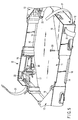
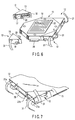
- FIGS. 1 to 9 show an artificial satellite according to a first embodiment.
- FIG. 1 is a perspective view of the artificial satellite that is folded
- FIG. 2 is a perspective view of the artificial satellite that is unfolded.
- nine panels of substantially the same size are coupled by a hinge mechanism, which will be described later, in such a manner that they can be folded to thereby constitute an artificial satellite 1.
- a mission equipment panel 3 is coupled to one end of a communication panel 2 such that they are flush with each other.
- a first CPU panel 4 is coupled to the other end of the mission equipment panel 3 at right angles.
- the mission equipment panel 3 is loaded with a device for optical observation, e.g., an optical device such as a lens having a long focal length.
- a power supply panel 5, a first attitude control panel 6 and a second CPU panel 7 are coupled in this order to the other end of the first CPU panel 4 such that they are flush with each other.
- An image sensor memory panel 8 is coupled to the other end of the second CPU panel 7 at right angles.
- a second attitude control panel 9 is coupled to the other end of the image sensor memory panel 8 such that they are flush with each other.
- the image sensor memory panel 8 and second attitude control panel 9 are parallel with the communication panel 2 and mission equipment panel 3.
- a third attitude control panel 10 is coupled to one side of the second attitude control panel 9 at right angles.
- the first, second and third attitude control panels 6, 9 and 10 are arranged in three directions that are perpendicular to each other and can generate three shifting attitude control forces.
- the artificial satellite 1 is shaped almost like a Japanese letter " " when it is unfolded.
- the panels 2 to 10 are folded in zigzags and bound with a binding rope 1a to allow the layered panels to be loaded on a rocket as shown in FIG. 1.
- the reason why the artificial satellite 1 is shaped almost like a Japanese letter " " is that the image sensor memory panel 8 picks up an image from the light that passed through a lens of the mission equipment panel 3 and observes the image optically.
- the panels 2 to 10 are basically of the same shape and size. Describing the first attitude control panel 6 as an example, it is configured as shown in FIGS. 3 to 9.
- the panel main body 11 is shaped like a flat box that is configured by a bottom plate 13, a side plate 14 corresponding to the sidewall, and a cover plate 15. Notches 16 are formed on their respective four sides of the side plate 14.
- Each of the corner panels 12 is also shaped like a flat box that is configured by a bottom plate 17, a side plate 18 corresponding to the sidewall, and a cover plate 19.
- the bottom plate 17 and cover plate 19 of each of the corner panels 12 are fixed to the bottom plate 13 and cover plate 15 of the panel main body 11 by bolts 20, respectively, with the result that the corner panels 12 are coupled to the panel main body 11.
- a hinge mechanism 21a is attached to the corner between the bottom plate 17 and side plate 18 of each of the corner panels 12 to couple adjacent panels rotatably to each other.
- the hinge mechanism 21a is energized by an energizing spring or the like in which direction the panels are coupled to each other.
- the present invention is not limited to the hinge mechanism 21a. Any mechanism can be used if it allows adjacent panels to be rotatably coupled to each other.
- a latch mechanism 21b is provided on the side plate 18 opposed to the hinge mechanism 21a. When the panels are unfolded, the unfolding conditions are held by the latch mechanism 21b.
- a solar panel 22 is stuck to the outer surface of the panel main body 11 to which sunlight is applied, such as the outer surfaces of the bottom plate 13 and cover plate 15.
- the solar panel 22 is electrically connected to a battery 23 located in the panel main body 11.
- the battery 23 includes a battery control unit 24.
- the panel main body 11 includes a controller 25, a LAN card 26, a wireless LAN antenna 27 and a functional element 28.
- the functional element 28 is electrically connected to the battery 23 and also connected to the controller 25 through a signal line.
- the functional element 28 is an attitude control device and an attitude change device (e.g., a device for storing and emitting angular momentum such as reaction wheel).
- the functional element 28 is a device for communicating with the ground.
- the panels 2 to 10 differ only in the functional element 28 and the other elements are the same.
- Adjacent panels each corresponding to the panel main body 11 are connected to each other by a tape-shaped thermal conductivity sheet 29 having flexibility, which is drawn out of the notches 16 through the panels.
- the thermal conductivity sheet 29 is adhered to part of the panel main body 11 or the device thereof by an adhesive (not shown).
- the thermal conductivity sheet 29 is a high thermal conductivity sheet and serves to bring a difference in temperature among the panels as close as possible to zero. In other words, the panels are varied in temperature due to how sunlight is applied, heat radiation from the control device in the panel main body 11, and the like. If, however, the panels are connected to each other by the thermal conductivity sheet 29, heat is quickly transferred from a higher-temperature panel to a lower-temperature panel to keep the temperature difference among all the panels almost constant.
- the panel main body 11 can be provided with a radiator.
- the radiator can dissipate heat into space and the thermal conductivity sheet 29 can radiate heat.
- a heater can be used as the prior artificial satellite to transfer its heat to the thermal conductivity sheet 29. Since the panels are coupled to each other by the thermal conductivity sheet 29, no heater is provided for each of the panels. The number of heaters can be reduced and so can be the number of controllers.
- the corner panels 12 include a power supply connector 30 and a flexible cord 31.
- the panels are electrically connected to each other through the power supply connector 30 and flexible cord 31 of the corner panels 12.
- the power generated from solar cells of each panel is used in the device in the panel and for charging the battery in the panel. Excess power is supplied to another panel that is short of power by the electrical connection.
- thermal conductivity sheet 29 is PGS Graphite Sheet (made by Panasonic), the thermal conductivity thereof is 800W/mK, and the thickness thereof is 0.15 mm.
- the name of the adhesive is 6030HK (made by Techno Alpha Co., Ltd.) and the thermal conductivity thereof is 60W/mK.
- the amount of heat Q that has to be transferred by the thermal conductivity sheet can be estimated as follows at worst: where Ws is the solar constant and S is the area of the panels.
- the transfer of heat among the panels is performed by the flow of heat through the thermal conductivity sheet and that of heat through the adhesive. Evaluating a difference in temperature required to transfer the heat of 120W given by the above equation (1) in each of the flows of heat, the results as shown in the following Tables 1 and 2 are obtained.
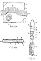
- FIGS. 10A and 10B show a second embodiment regarding a method of applying a thermal conductivity sheet.
- the panel main body 11 includes a loaded device 32 and an aluminum honeycomb panel 33 in space other than that for the loaded device 32.
- the thermal conductivity sheet 29 is bonded to the top surface of the loaded device 32.
- the aluminum honeycomb panel 33 can prevent the temperature of the panel main body 11 from becoming nonuniform in the thickness direction of the panel main body 11. While the thermal conductivity sheet 29 is bonded to the top surface of the loaded device 32, heat is transmitted through the panel main body 11 using the thermal conductivity sheet 29. The heat generated from the loaded device 32 can be transferred to adjacent panels by the thermal conductivity sheet 29, and a difference in temperature can be reduced.
- the artificial satellite 1 is loaded on a rocket 34 as shown in FIG. 11 while it is folded compact as shown in FIG. 1.
- the rocket 34 shown in FIG. 11 includes a rocket main body 35 under which a main engine 36 and a thrust augmentation fixed fuel rocket motor 37 are provided. Different fuel tanks 38 and a second-stage engine 39 are provided halfway in the rocket main body 35.
- a loaded-object connecting structure 40 is provided above the rocket main body 35 to be surrounded by a nose fairing 41.
- the artificial satellite 1 is loaded into the upper space 42 of the loaded-object connecting structure 40.
- the rocket is adequately large as shown in FIG. 11, it can load a very large artificial satellite and additionally a second or third artificial satellite beside the loaded-object connecting structure 40.
- the nose fairing 41 is divided and the rocket engine is completely burnt, the artificial satellite 1 is released into the space and unfolded as shown in FIG. 2.
- a plurality of rectangular panels are coupled rotatably by the hinge mechanism and can be folded when they are launched aboard a rocket and unfolded in space after they are launched.
- the shape of the panels and the number of panels are taken as one example, and the present invention is not limited to these shape and number.
- the unfolded states vary with the increase and decrease of panels in number and how the panels are connected.
- a panel with a function or a device loaded on the panel can appropriately be varied with user's requests.
- the present invention is not limited to the panels or devices of the above embodiments.
- the panels differ in function but have their mechanical, electrical and data interfaces in common. It is thus possible to enhance commonality of inspecting devices and inspecting procedures in the inspection or the ground test during the manufacture. In particular, the commonality of inspecting devices contributes to a reduction in costs and development period.
- the commonality of interfaces can apply to the inside of the panels. Since the interface that the mounted equipment (functional element 28) contacts in the artificial satellite is standardized in this invention, the conditions for developing the functional element 28 are unified in advance. The design target is therefore easy to set. In the development of prior artificial satellites, a large variety of functional elements 28 constitute interfaces therebetween and thus all the elements are often developed at the same time. It is thus only general big companies that can work on the development of the functional elements 28.
- the artificial satellite according to the present invention can be folded compact when it is launched aboard a rocket and its functions can be extended and reduced, thereby reducing in costs and development period.
- An artificial satellite can be launched into space aboard a rocket to allow communications with the ground and observation of the earth or other functions, and its functions can be extended and reduction.
Landscapes
- Engineering & Computer Science (AREA)
- Remote Sensing (AREA)
- Aviation & Aerospace Engineering (AREA)
- Physics & Mathematics (AREA)
- Astronomy & Astrophysics (AREA)
- General Physics & Mathematics (AREA)
- Automation & Control Theory (AREA)
- Chemical & Material Sciences (AREA)
- Combustion & Propulsion (AREA)
- Radar, Positioning & Navigation (AREA)
- Photovoltaic Devices (AREA)
Abstract
Description



| Thermal Conductivity | 800W/mk |
| Thickness of Sheet | 0.4 mm |
| Width of Connected Panels | 80 mm |
| Distance between | 1 mm |
| Difference in Temperature | 4.7K |
| Amount of Heat to be Transferred | 120W |
| Thermal Conductivity | 60W/mk |
| Area of | 25 cm2 |
| Thickness of Adhesion | 0.2 mm |
| Difference in Temperature | 0.16K |
| Amount of Heat to be Transferred | 120W |
Claims (8)
- An artificial satellite that is launched into space aboard a rocket, the artificial satellite including a plurality of panels coupled rotatably by a hinge mechanism, the panels being folded when the artificial satellite is launched aboard the rocket and unfolded in the space after the artificial satellite is released, each of the panels being loaded with at least a battery and a communication device separately or together, and power and information being transferred between communication devices of the panels.
- The artificial satellite according to claim 1, wherein said plurality of panels include a communication panel, a CPU panel, a power panel, an attitude control panel, a heat control panel and a mission equipment panel, which are loaded with the device.
- The artificial satellite according to claim 1, wherein the panels each have a flat box structure that stores at least one of functional elements such as a battery, an attitude control device, a calculation device and a communication device and has a solar panel on an outer surface thereof.
- The artificial satellite according to claim 1, wherein the panels each include a rectangular panel main body and corner panels provided at corner sections of the panel main body, and the corner panels each have a hinge mechanism by which the panels are coupled to each other.
- The artificial satellite according to claim 4, wherein the corner panels each have a connector for a power supply line and a signal line through which the panels are electrically connected to each other.
- The artificial satellite according to claim 1, wherein adjacent ones of the panels are coupled to each other by a thermal conductivity sheet having flexibility.
- The artificial satellite according to claim 6, wherein the thermal conductivity sheet having flexibility is brought into contact with the devices loaded on the panels.
- The artificial satellite according to claim 1, wherein the panels each have an aluminum honeycomb structure in space other than that for the device.
Applications Claiming Priority (3)
| Application Number | Priority Date | Filing Date | Title |
|---|---|---|---|
| JP2002309645A JP4094930B2 (en) | 2002-10-24 | 2002-10-24 | Artificial satellite |
| JP2002309645 | 2002-10-24 | ||
| PCT/JP2003/013576 WO2004037644A1 (en) | 2002-10-24 | 2003-10-23 | Artificial satellite |
Publications (3)
| Publication Number | Publication Date |
|---|---|
| EP1559649A1 true EP1559649A1 (en) | 2005-08-03 |
| EP1559649A4 EP1559649A4 (en) | 2005-12-21 |
| EP1559649B1 EP1559649B1 (en) | 2007-04-04 |
Family
ID=32171013
Family Applications (1)
| Application Number | Title | Priority Date | Filing Date |
|---|---|---|---|
| EP03758838A Expired - Lifetime EP1559649B1 (en) | 2002-10-24 | 2003-10-23 | Artificial satellite |
Country Status (6)
| Country | Link |
|---|---|
| US (1) | US7156349B2 (en) |
| EP (1) | EP1559649B1 (en) |
| JP (1) | JP4094930B2 (en) |
| AU (1) | AU2003275622A1 (en) |
| DE (1) | DE60313015T2 (en) |
| WO (1) | WO2004037644A1 (en) |
Cited By (5)
| Publication number | Priority date | Publication date | Assignee | Title |
|---|---|---|---|---|
| EP2407384A1 (en) * | 2010-07-16 | 2012-01-18 | The Boeing Company | Dual evolved expendable launch vehicle (EELV) secondary payload adaptor (ESPA) port small satellite design |
| EP2386489A3 (en) * | 2010-05-14 | 2017-01-18 | Japan Aerospace Exploration Agency | Panel type artificial satellite and artificial satellite system therewith |
| EP3431398A1 (en) * | 2017-07-21 | 2019-01-23 | Technische Universität München | Satellite cover panel |
| WO2019160430A1 (en) * | 2018-02-19 | 2019-08-22 | Mazarom Impex S.R.L. | Small-size artificial satellite - "card-sat" |
| WO2019171062A1 (en) * | 2018-03-07 | 2019-09-12 | Oxford Space Systems Limited | Deployable spacecraft body |
Families Citing this family (17)
| Publication number | Priority date | Publication date | Assignee | Title |
|---|---|---|---|---|
| JP4532425B2 (en) * | 2006-03-22 | 2010-08-25 | 三菱電機株式会社 | Satellite equipment panel |
| US8005518B1 (en) | 2006-12-21 | 2011-08-23 | Adobe Systems Incorporated | Configurable multi-dimensional media device |
| USD609203S1 (en) * | 2007-08-30 | 2010-02-02 | Adobe Systems, Incorporated | Media device |
| US8905357B1 (en) * | 2009-10-02 | 2014-12-09 | MMA Design, LLC | Thin membrane structure |
| US9550584B1 (en) | 2010-09-30 | 2017-01-24 | MMA Design, LLC | Deployable thin membrane apparatus |
| CN102514730A (en) * | 2011-12-21 | 2012-06-27 | 哈尔滨工业大学 | Electromechanical and thermal integrated satellite structure |
| FR3041608B1 (en) * | 2015-09-25 | 2018-04-13 | Thales Sa | DEPLOYABLE ASSEMBLY |
| WO2018209185A1 (en) | 2017-05-11 | 2018-11-15 | Roccor, Llc | Integrated power module devices, systems, and methods |
| CN109110158B (en) * | 2018-07-26 | 2022-07-12 | 西北工业大学 | Chip satellite group and its distribution method |
| CN109592077B (en) * | 2018-12-25 | 2024-05-31 | 中国科学院西安光学精密机械研究所 | A flexible and modular satellite |
| CN114148546B (en) * | 2021-11-17 | 2023-08-18 | 北京九天微星科技发展有限公司 | a satellite configuration |
| JP7679803B2 (en) | 2022-07-08 | 2025-05-20 | トヨタ自動車株式会社 | Solar power generation equipment |
| CN116176861B (en) * | 2022-12-12 | 2025-12-23 | 中国科学院力学研究所 | A Deformable Flexible Satellite and Its Manufacturing Method |
| US12497195B2 (en) * | 2023-10-12 | 2025-12-16 | United States Of America As Represented By The Secretary Of The Air Force | Articulating spacecraft chassis |
| FR3163351A1 (en) * | 2024-06-13 | 2025-12-19 | Thales | Space platform and method for deploying such a platform |
| FR3163352A1 (en) * | 2024-06-13 | 2025-12-19 | Thales | Space module intended to be deployed in space to form a space platform and associated space platform |
| AT528428A2 (en) * | 2024-06-27 | 2026-01-15 | Lili Weinmann Eichinger | Modular satellite system |
Family Cites Families (13)
| Publication number | Priority date | Publication date | Assignee | Title |
|---|---|---|---|---|
| US3346419A (en) * | 1963-11-29 | 1967-10-10 | James E Webb | Solar cell mounting |
| US4394529A (en) * | 1981-08-05 | 1983-07-19 | Rca Corporation | Solar cell array with lightweight support structure |
| JPS6150100A (en) | 1984-08-20 | 1986-03-12 | 株式会社日立製作所 | Pressure-suppression chamber clad transport system |
| JPS6150100U (en) * | 1984-09-06 | 1986-04-04 | ||
| JPS62191300A (en) * | 1986-02-18 | 1987-08-21 | 三菱電機株式会社 | Expandion type solar cell array |
| US5785280A (en) * | 1995-07-20 | 1998-07-28 | Space Systems/Loral, Inc. | Hybrid solar panel array |
| EP0849166A1 (en) | 1996-12-20 | 1998-06-24 | TRW Inc. | Modular spacecraft architecture |
| US5961076A (en) * | 1996-12-20 | 1999-10-05 | Trw Inc. | Modular spacecraft development process |
| EP0869063A1 (en) | 1996-12-20 | 1998-10-07 | TRW Inc. | Power, data and RF buses for modular spacecraft |
| GB9803918D0 (en) * | 1997-07-05 | 1998-04-22 | Matra Marconi Space Uk Ltd | Spacecraft platforms |
| JP3473831B2 (en) | 1999-03-12 | 2003-12-08 | 宇宙開発事業団 | Module connection type space structure and attitude control method thereof |
| JP2000350345A (en) * | 1999-06-02 | 2000-12-15 | Mitsubishi Electric Corp | Deployable structure in which a plurality of structural elements are combined and a method of mounting the wire rod |
| US6568638B1 (en) * | 2000-11-07 | 2003-05-27 | Lockheed Martin Corporation | Modular spacecraft structure |
-
2002
- 2002-10-24 JP JP2002309645A patent/JP4094930B2/en not_active Expired - Lifetime
-
2003
- 2003-10-23 EP EP03758838A patent/EP1559649B1/en not_active Expired - Lifetime
- 2003-10-23 DE DE60313015T patent/DE60313015T2/en not_active Expired - Lifetime
- 2003-10-23 AU AU2003275622A patent/AU2003275622A1/en not_active Abandoned
- 2003-10-23 WO PCT/JP2003/013576 patent/WO2004037644A1/en not_active Ceased
-
2005
- 2005-04-21 US US11/110,872 patent/US7156349B2/en not_active Expired - Lifetime
Cited By (9)
| Publication number | Priority date | Publication date | Assignee | Title |
|---|---|---|---|---|
| EP2386489A3 (en) * | 2010-05-14 | 2017-01-18 | Japan Aerospace Exploration Agency | Panel type artificial satellite and artificial satellite system therewith |
| EP2407384A1 (en) * | 2010-07-16 | 2012-01-18 | The Boeing Company | Dual evolved expendable launch vehicle (EELV) secondary payload adaptor (ESPA) port small satellite design |
| US8550408B2 (en) | 2010-07-16 | 2013-10-08 | The Boeing Company | Dual evolved expendable launch vehicle (EELV) secondary payload adaptor (ESPA) port small satellite design |
| EP3431398A1 (en) * | 2017-07-21 | 2019-01-23 | Technische Universität München | Satellite cover panel |
| US11097858B2 (en) | 2017-07-21 | 2021-08-24 | Technische Universität München | Satellite cover panel |
| WO2019160430A1 (en) * | 2018-02-19 | 2019-08-22 | Mazarom Impex S.R.L. | Small-size artificial satellite - "card-sat" |
| US11465780B2 (en) | 2018-02-19 | 2022-10-11 | Mazarom Impex S.R.L. | Small-size artificial satellite—“Card-Sat” |
| WO2019171062A1 (en) * | 2018-03-07 | 2019-09-12 | Oxford Space Systems Limited | Deployable spacecraft body |
| US11518548B2 (en) | 2018-03-07 | 2022-12-06 | Oxford Space Systems Limited | Deployable spacecraft body |
Also Published As
| Publication number | Publication date |
|---|---|
| DE60313015T2 (en) | 2007-12-13 |
| EP1559649A4 (en) | 2005-12-21 |
| JP2004142592A (en) | 2004-05-20 |
| EP1559649B1 (en) | 2007-04-04 |
| US20050230558A1 (en) | 2005-10-20 |
| AU2003275622A1 (en) | 2004-05-13 |
| WO2004037644A1 (en) | 2004-05-06 |
| JP4094930B2 (en) | 2008-06-04 |
| DE60313015D1 (en) | 2007-05-16 |
| US7156349B2 (en) | 2007-01-02 |
Similar Documents
| Publication | Publication Date | Title |
|---|---|---|
| EP1559649B1 (en) | Artificial satellite | |
| US5979833A (en) | Modular spacecraft architecture | |
| US5314146A (en) | Multi-mission spacecraft bus having space frame structural design | |
| US9889951B1 (en) | Spacecraft east-west radiator assembly | |
| US20050211850A1 (en) | Two-sided deployable thermal radiator system and method | |
| US5931418A (en) | Functionally independent spacecraft module | |
| EP0780302B1 (en) | Device and method for equalizing heat dissipation between multiple radiators on a spacecraft | |
| US5634612A (en) | Earth orbiting satellite having electrical energy storage batteries | |
| US8720831B2 (en) | Spacecraft panel architecture | |
| CN113815899A (en) | A cellular satellite system that can be modularly assembled and reconfigured in orbit | |
| JP4523974B2 (en) | Artificial satellite | |
| RU2688630C2 (en) | Space platform | |
| CN117644996B (en) | An optical satellite | |
| Sozbir et al. | Design of thermal control subsystem for TUSAT telecommunication satellite | |
| Tuttle et al. | Thermal design of the Mercury transfer module | |
| Rossoni et al. | Developments in nano-satellite structural subsystem design at NASA-GSFC | |
| Barton et al. | Modular thermal design concepts: Thermal design of a spacecraft on a module level for LEO missions | |
| Sozbir et al. | Thermal control of CM and SM panels for Turkish satellite | |
| Fosness et al. | Multifunctional structures | |
| Homan et al. | The challenges of developing an operational nanosatellite | |
| Braig et al. | Rosetta-Journey in the Outer Solar System Without Nuclear Energy | |
| Ercol et al. | The MESSENGER spacecraft power subsystem thermal design and early mission performance | |
| Foster et al. | Thermal management issues for multifunctional solar arrays | |
| Pitz et al. | Special Features of the CLUSTER Thermal Control Concept | |
| R Anderson et al. | Thermal Systems Engineering Design and Analysis of a High Usability Host Spacecraft |
Legal Events
| Date | Code | Title | Description |
|---|---|---|---|
| PUAI | Public reference made under article 153(3) epc to a published international application that has entered the european phase |
Free format text: ORIGINAL CODE: 0009012 |
|
| 17P | Request for examination filed |
Effective date: 20050524 |
|
| AK | Designated contracting states |
Kind code of ref document: A1 Designated state(s): AT BE BG CH CY CZ DE DK EE ES FI FR GB GR HU IE IT LI LU MC NL PT RO SE SI SK TR |
|
| AX | Request for extension of the european patent |
Extension state: AL LT LV MK |
|
| A4 | Supplementary search report drawn up and despatched |
Effective date: 20051108 |
|
| DAX | Request for extension of the european patent (deleted) | ||
| RBV | Designated contracting states (corrected) |
Designated state(s): DE FR GB |
|
| GRAP | Despatch of communication of intention to grant a patent |
Free format text: ORIGINAL CODE: EPIDOSNIGR1 |
|
| GRAS | Grant fee paid |
Free format text: ORIGINAL CODE: EPIDOSNIGR3 |
|
| GRAA | (expected) grant |
Free format text: ORIGINAL CODE: 0009210 |
|
| AK | Designated contracting states |
Kind code of ref document: B1 Designated state(s): DE FR GB |
|
| REG | Reference to a national code |
Ref country code: GB Ref legal event code: FG4D |
|
| REF | Corresponds to: |
Ref document number: 60313015 Country of ref document: DE Date of ref document: 20070516 Kind code of ref document: P |
|
| ET | Fr: translation filed | ||
| PLBE | No opposition filed within time limit |
Free format text: ORIGINAL CODE: 0009261 |
|
| STAA | Information on the status of an ep patent application or granted ep patent |
Free format text: STATUS: NO OPPOSITION FILED WITHIN TIME LIMIT |
|
| 26N | No opposition filed |
Effective date: 20080107 |
|
| REG | Reference to a national code |
Ref country code: FR Ref legal event code: PLFP Year of fee payment: 14 |
|
| REG | Reference to a national code |
Ref country code: FR Ref legal event code: PLFP Year of fee payment: 15 |
|
| REG | Reference to a national code |
Ref country code: FR Ref legal event code: PLFP Year of fee payment: 16 |
|
| PGFP | Annual fee paid to national office [announced via postgrant information from national office to epo] |
Ref country code: GB Payment date: 20220908 Year of fee payment: 20 |
|
| PGFP | Annual fee paid to national office [announced via postgrant information from national office to epo] |
Ref country code: FR Payment date: 20220921 Year of fee payment: 20 |
|
| PGFP | Annual fee paid to national office [announced via postgrant information from national office to epo] |
Ref country code: DE Payment date: 20221027 Year of fee payment: 20 |
|
| REG | Reference to a national code |
Ref country code: DE Ref legal event code: R071 Ref document number: 60313015 Country of ref document: DE |
|
| REG | Reference to a national code |
Ref country code: GB Ref legal event code: PE20 Expiry date: 20231022 |
|
| PG25 | Lapsed in a contracting state [announced via postgrant information from national office to epo] |
Ref country code: GB Free format text: LAPSE BECAUSE OF EXPIRATION OF PROTECTION Effective date: 20231022 |
|
| PG25 | Lapsed in a contracting state [announced via postgrant information from national office to epo] |
Ref country code: GB Free format text: LAPSE BECAUSE OF EXPIRATION OF PROTECTION Effective date: 20231022 |