The present invention relates generally to the art of welding
power supplies, and more particularly relates to the control
of wire feed speed and a power source of a short circuit welding
machine.
BACKGROUND OF THE INVENTION
There are many types of welding power supplies used for a variety
of welding processes. Welding power supply typically includes
a wire feeder, a power source, a torch or gun, a wire
feeder controller, and a power source controller to control
the various components. These components of the welding power
supply may share a housing, or be encased in separate housings.
The power source of the welding power supply typically
includes the power circuitry of the welder (e.g., rectifiers,
switches, transformers, SCRs, etc.) that process and provide
the output power of the welding power supply. The power source
controller of the welding power supply typically includes
digital and/or analog circuitry, discrete and/or integrated
circuitry, microprocessors, DSPS, etc., software, hardware,
and/or firmware which are used to control a welding process,
or a device such as a power source and/or wire feeder.
Arc welding power supply sources used for MIG welding normally
include at least two welding controls. One of the welding controls
is for control of arc voltage and the other welding control
is for control of wire feed speed. It is not uncommon for
the MIG welders to include additional controls to enable more
precise control for the welding process. Indeed, some welding
applications are so demanding that the welding power source
includes several welding controls to achieve the required results
for a particular welding application. There are, however,
many "simple" welding applications which do not require
precise control for the welding process. MIG welders that are
designed for such applications include fewer welding controls
and are typically priced lower than the more complex models.
Although these welding machines designed for simple welding
applications are less complex in design, these welding machines
still include a plurality of welding controls for the
arc voltage and/or current level of the output current of the
welder and for wire feed speed. As a result, these welding
controls must be properly selected in order to obtain an acceptable
weld in even these simple welding applications. The
required setting of two or more welding controls adds additional
complexity to a welding process and increases the incidence
of an improper weld being formed for a particular application.
In view of the prior art, there is a need for an arc welder
that is low cost, that is simple to operate and which generates
a desired current level for a particular wire feed speed
by use of fewer user controlled inputs.
SUMMARY OF THE INVENTION
The present invention is directed to an apparatus and method
of arc welding and more particularly directed to an apparatus
and method of MIG welding that includes a simplified control
arrangement for the current output level of the welder, and
the control of the wire feed speed. Although the invention
will be described with particular reference to MIG welder, it
will be appreciated that the invention can be expanded to
other types of welding.
In accordance with one aspect of the present invention, there
is provided a welder having a welding power source, a wire
feeder and a wire feed speed controller. The welder is designed
particularly for MIG (solid wire and gas) applications.
The welder has a simplified design in that the welder includes
a single wire feed control that controls both the wire feed
speed of the consumable electrode and the arc welding voltage
and/or current level of the welding power source. As a result,
the welder of the present invention significantly simplifies
the welding process by enabling an operator to select a particular
wire feed speed which selection automatically generates
an appropriate arc welding voltage and/or current level
for the selected wire feed speed. In one embodiment of the invention,
the wire feed speed selector generates a signal that
is used by a wire feed speed controller to control the actual
wire feed speed of an electrode being fed to a workpiece. The
wire feed speed selector is typically a potentiometer that
generates a linear signal; however, a non-linear signal can be
generated by the potentiometer. As can be appreciated, the
wire feed speed selector can be a digital selector or any
other type of selector which can generate a control signal.
The control signal generated by the wire feed speed selector
is typically directed to a hard wire circuit and/or a microprocessor
which converts the signal into a control current or
voltage used to drive the motor of a wire feeder. As can be
appreciated, the signal from the wire feed speed selector can
be used to directly control the motor of the wire feeder. In
another and/or alternative aspect of the invention, the signal
generated by the wire feed speed selector is directed to a
welding output controller that in turn generates a signal to
the welding power source control SCRs, FETs, IGBTs, etc., to
control the arc welding voltage and/or current. The welder
output controller is designed to increase or decrease the arc
voltage and/or current generated by the power supply of the
arc welder as the wire feed speed control is changed. This
particular control design for an arc welder enables the operator
to control both the wire feed speed and the arc welding
voltage and/or current by a single control knob or selector.
This simplified design results in reduced manufacturing costs
of the welder by reducing the number of parts, and simplifies
a welding operation by reducing the number of control knobs on
the welder.
In accordance with another and/or additional aspect of the
present invention, there is provided a welder which includes a
function generator that generates a particular control signal
to the power source control based upon a signal received from
the wire feed speed selector. The function generator can include
a hard wire circuit, a microprocessor, a function table,
a software program, etc. which generates one or more control
signals based upon a signal received from the wire feed speed
selector. As such, the function generator creates a particular
relationship between the selected wire feed speed and the
voltage and/or current of the arc generated by the power supply.
In one embodiment of the invention, the function generator
is part of a wave shape network designed to generate an
arc welding voltage based upon a particular relationship with
the signal generated by the wire feed speed selector. In one
non-limiting aspect of this embodiment, the function generator
generates an arc welding voltage based upon the following
equation:
V(Arc Volts) = 20 + 0.04 x I(Arc Amps)
V(Arc Volts) is the voltage level of the arc formed between
the electrode and a workpiece. I(Arc Amps) is the current
level of the arc formed between the electrode and workpiece.
The factor "20" in the equation relates to use of a particular
shielding gas such as carbon monoxide or carbon dioxide. This
value can be modified when other shielding gases are selected.
For instance, a lower value would typically be selected when a
shielding gas is comprised primarily of argon. The factor
"0.04" in the equation represents the slope of the linear relationship
between the arc volts and arc current. As can be
appreciated, other values can be used. As can also be appreciated,
the relationship between the arc voltage and arc current
can be non-linear.
This equation can be modified by making the arc amps (I) proportional
to the wire feed speed. As a result, the equation
can be modified to be expressed as:
V(Arc Volts) = 20 + 0.04 x (WFS Volts) x K
K is a constant which is selected so that the proper magnitude
of (WFS volts) x K is equal to the welding current being generated
by the power supply. As is represented by the relationship
above, a linear relationship is thus formed between the
arc welding voltage and the selected wire feed speed. As can
be appreciated, the function generator can include equations
and/or various types of relationships to generate a non-linear
relationship between the arc welding voltage and the wire feed
speed. In addition, the resultant signal from the function
generator can be further conditioned by the SCR firing circuit
or other power source controllers such that the dynamic range
of the arc welding voltage is within the control range of the
control circuit. Consequently, the linear equation set forth
above is but one of many equations that can be used.
In still another and/or alternative aspect of the present invention,
there is provided a welder which includes one or more
controls designed to adjust the control signal generated by
the function generator. The use of a particular diameter of
electrode, type of electrode, and/or shielding gas mixture can
affect the quality of the weld. In the simplest design of the
arc welder in accordance with the present invention, the
welder includes a single control knob or selector to adjust
the wire feed speed during a welding operation and uses the
signal from the selected wire feed speed to also control the
arc welding voltage and/or current generated by the welding
power supply. In this particular design, an operator simply
increases or decreases the wire feed speed for a particular
welding application. The function generator of the wave shape
network in the welder can be factory set for a nominal arc
voltage-arc current relationship. For instance, the welding
machine could be designed for use with a 0.035 inch diameter
low carbon solid wire which uses a shielding gas mixture of
about 75% argon and 25% carbon dioxide. So long as an operator
uses this particular type of welding wire having this particular
diameter in conjunction with this particular shielding gas
mixture, a desired weld bead will be formed. However, if the
operator deviates from these factory set parameters, the quality
of the weld bead may be reduced. In order to accommodate
the use of different types of welding wire, different diameters
of welding wire and/or different types of shielding
gases, the welder of the present invention may include one or
more manual switches or selections used to define the type of
electrode, the size of the electrode and/or the type of
shielding gas used in a particular welding operation, and
thereby appropriately change the output function generator of
the wave shape network. In one embodiment of the invention,
one or more manually controlled switches or selectors are inserted
on the arc welder to enable an operator to select a
particular type of electrode, a particular size of electrode
and/or a particular type of shielding gas. In another and/or
alternative embodiment of the present invention, the arc
welder includes one or more internal switches or controllers
designed to automatically detect the type of electrode being
used, the diameter.of the electrode being used and/or the type
of shielding gas being used and automatically change or modify
the output of the function generator of the wave shape network
in accordance with one or more of these detected values. In
this particular design of the welder, the simplicity of the
welder is maintained since the operator still uses only a single
wire feed speed knob or selector to control the wire feed
speed and the arc welding voltage and/or current of the
welder. Any modification to the relationship between the selected
wire feed speed and the arc welding voltage and/or current
is automatically adjusted based upon the detected electrode
type, electrode diameter and/or shielding gas type by
the welding machine.
The primary object of the present invention is the provision
of an apparatus and method of welding that is simple and cost
effective to use.
Another object of the present invention is the provision of an
apparatus and method of welding that controls the wire feed
speed and the welding arc voltage and/or current based upon a
selected wire feed speed.
Still another and/or alternative object of the present invention
is the provision of an apparatus and method of welding
that includes a wave shape network for controlling the arc
welding voltage and/or current as a function of the wire feed
speed during a welding operation.
Yet another and/or alternative object of the present invention
is the provision of an apparatus and method of welding that
includes a wave shape network for controlling the arc welding
voltage and/or current which includes a modifiable relationship
between the wire feed speed and the welding arc voltage
and/or current based upon a detected and/or selected electrode
type, electrode size and/or shielding gas type.
Still yet another and/or alternative object of the present invention
is the provision of an apparatus and method of welding
that includes a wire feed speed selector that can be used by
an operator to select a wire feed speed and to automatically
select an appropriate arc welding voltage and/or current for a
particular operation so as to generate a high quality weld
bead during a particular welding operation.
A further and/or alternative object of the present invention
is the provision of an apparatus and method of welding that is
simpler to use than previously available arc welders.
Still a further and/or alternative object of the present invention
is the provision of an apparatus and method of welding
that includes a welder having less user-selectable controls so
as to simplify a welding procedure.
Still yet a further and/or alternative object of the present
invention is the provision of an apparatus and method of welding
that includes a low cost welder having a simplified user
control arrangement and which produces a high quality weld
bead during a welding operation.
These and other objects and advantages will become apparent
from the following description taken together with the accompanying
drawing.
BRIEF DESCRIPTION OF DRAWINGS
Reference may now be made to the drawings, which illustrate
various embodiments that the invention may take in physical
form and in certain parts and arrangements of parts wherein;
DESCRIPTION OF THE PREFERRED EMBODIMENTS
While the present invention will be illustrated with reference
to a particular welding power supply, used in a particular
process, and implemented with particular components, it should
be understood that the invention can also be implemented with
other welding power supplies, other processes, and implemented
with other components, software, hardware etc. Generally, the
various aspects of this invention will be described using a
MIG welding power supply; however, it will be understood that
the concepts of the present invention can be used in other
types of arc welding processes. This embodiment includes a
power source and a wire feeder that can be housed in a single
housing, or in multiple housings.
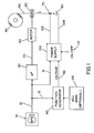
Referring now to FIG. 1, there is disclosed a welding control
arrangement for a MIG welding power supply in accordance with
the present invention. A wire feed speed selector 10 is typically
a potentiometer used to generate a control signal based
upon a selected wire feed speed. The control signal typically
ranges between 1-5 volts; however, other volt ranges can be
used. Typically, the potentiometer is a linear potentiometer;
however, a non-linear potentiometer can be used. As also can
be appreciated, the potentiometer can be substituted for a
digital selector or other type of selector. The voltage signal
generated by the wire feed speed selector is carried by line
12 to a microprocessor 20, the welding power supply 100 and a
function generator 90. Microprocessor 20 converts the signal
received on line 12 to a controlled voltage which in turn is
directed along line 22 to the wire feed speed motor 30. The
wire feed speed motor drives the wire rollers 60 to feed the
consumable wire electrode 50 from the wire reel 40 to a welding
gun. As can be appreciated, the microprocessor 20 can be
substituted for a hard wired circuit and/or can be eliminated
by designing the motor to generate a speed that is directly
proportional to the signal generated by the wire feed speed
selector along line 12. The operation and control of the wire
feed speed motor by a wire feed selection is well known in the
art, thus will not be further described.
Electrode 50 is typically a solid low carbon wire electrode
having a diameter of about 0.035 inch; however, the wire electrode
can be a flux cored electrode and/or an electrode having
a diameter greater than or less than about 0.035 inch. Typically,
the composition and type of electrode, and/or diameter
of the electrode is selected for a particular welding operation
to weld a particular type of workpiece.
As shown in FIG. 1, the control signal along line 12 is directed
into a function generator 90. The function generator is
designed to cause the power supply 100 to generate a particular
wave shape for the arc welding voltage and/or current that
is directed along lines 102 and 104 to the electrical contacts
70 of the welding gun and workpiece 80, respectively. The
function generator is designed to generate an arc voltage signal
along line 92 that is based on or proportional to the signal
received along line 12. The function generator can include
a hard wired circuit, a microprocessor, a software program, a
function table and/or the like to generate the desired arc
voltage signal along line 92. In one non-limiting arrangement,
the function generator includes a hard wired circuit or a microprocessor
that generates an arc voltage signal along line
92. For MIG welding, the following control relationship between
arc voltage and arc amps can be used:
V(Arc Volts) = 20 + 0.04 x I(Arc Amps)
The factor "20" in the equation relates to an arc shielded by
carbon monoxide and/or carbon dioxide gas. If another type of
shielding gas is used, this factor may be increased or reduced.
For instance, if the arc shielding gas is primarily
comprised of argon, the factor will typically be less than
"20". The proportionality factor of 0.04 defines the linear
sloped relationship between the arc voltage and arc amps. When
certain types of welding electrodes are used, this proportionality
factor may be increased or reduced to achieve a desired
weld bead quality for a particular welding operation.. The arc
amps can be made proportional to the voltage applied to the
wire feed motor 30 used to drive the wire electrode to the
welding gun. As a result, the following linear relationship is
established between the welding arc voltage generated by the
power supply and the voltage signal generated by the wire feed
speed selector along line 12:
V(Arc Volts) = 20 + 0.04 x (WFS Volts) x K
WFS volts is the voltage along line 12. The constant K is a
proportionality value that is set to the proper magnitude to
achieve the linear relationship between the wire feed speed
control signal and the actual welding current. By incorporating
this linear function into the function generator, a relationship
is established between the wire feed speed control
signal and the arc welding voltage and/or current and between
the wire feed speed signal and the wire feed motor speed. This
linear relationship is illustrated in FIG. 3. As described
above, the function generator 90 generates a signal having a
linear relationship between the wire feed speed selector and
the current and/or voltage levels to be generated by the power
supply; however, non-linear relationships can be generated by
function generator 90.
The power supply 100 can be designed to generate voltages of
120 and/or 240 and can be designed to generate any type of
current wave form depending on a particular welding application.
As shown in FIG. 1, an on/off switch 110 is provided to
activate and deactivate the power supply of the arc welder.
Typically, switch 110 is located on the front panel of the arc
welder. As so far described above, the simplest aspect of the
invention has been described.
FIG. 1 also illustrates a wire adjustment selector 120 which
can be included on the welder. The wire adjustment selector
can be used by an operator to select the size and/or type of
welding wire 50 which is used in a particular welding operation.
By selecting the particular type and/or size of electrode,
the signal from the function generator can be modified
so that the appropriate arc welding voltage and/or current is
supplied to a workpiece during a welding operation with a particular
size/type of electrode. As can be appreciated, the
wire adjustment selector can additionally and/or alternatively
include a shielding gas selector which can also be used to adjust
the signal from the function generator so as to adjust
the arc welding voltage and/or current during the welding of
the workpiece during the use of a particular shielding gas.
One example of an adjustment to the function generator by adjustment
selector 120 can be that the constant used in the
linear relationship between the arc volts and the wire feed
speed volts is increased and/or decreased. As described above,
numeral constant 20 can be increased or decreased when a particular
type of electrode is selected, a particular size of
electrode is selected and/or a particular type of shielding
gas is selected. In addition to the numerical constant being
adjusted by selector 120, the proportionality constant of 0.04
set forth in the non-limiting example above can be increased
or decreased depending on the particular type of electrode selected,
the particular size of electrode selected and/or the
particular type of shielding gas selected. As can be appreciated,
selector 120 can be used to modify function generator 90
so as to generate a desired voltage signal along line 92. If
the function generator is used in a particular function table,
software program, etc., adjustor 120 can be used to modify or
select a particular function table to be used, and/or a particular
algorithm to be used so as to generate the desired
voltage signal along line 92.
Referring now to FIG. 3, there are illustrated three linear
relationships between the wire feed speed signal (WFS Volts)
and the voltage of the arc (Arc Volts). As the wire feed speed
signal increases, resulting in an increase in the speed the
consumable electrode or wire is fed through the welding gun,
the voltage of the arc increases in a linear relationship. The
center linear line represents the preset values of the welder.
If the welder does not include a shielding gas selector and/or
an electrode selector, the central linear line represents the
set relationship between the feed speed of the electrode and
the voltage and current of the welding arc. The top and bottom
linear lines represent additional linear relationships between
the feed speed of the electrode and the voltage and current of
the welding arc. These additional linear relationships are
used when the welder includes a shielding gas selector and/or
an electrode selector. The selection of a particular shielding
gas or electrode can result in a different linear relationship
(e.g., increased or decreased relationship) from the normal or
common linear relationship (the center linear line) to be selected
so as to obtain a better weld bead when using a particular
shielding gas and/or electrode during an arc welding
procedure.
Referring now to FIG. 2, an electrical circuit is disclosed.
The wire feed speed selector 10 is represented by a potentiometer
represented by resistor R1. The voltage signal from the
potentiometer passes through line 12 and into an amplifier 24
which increases the voltage along line 22, which in turn is
used to control the speed of motor 30. As illustrated in FIG.
2, the signal from the wire feed speed selector is first amplified
prior to being directed to the function generator,
whereas in FIG. 1, the signal is directed directly to the
function generator. As can be appreciated, no modifications or
other additional modifications to the signal generated by the
wire feed speed selector can be used prior to the signal being
directed to the wire feed speed motor and/or function generator.
As illustrated in FIG. 2, the wire feed motor 30 drives a
welding electrode 50 through welding gun 72 to direct the wire
to workpiece 80 and form a desired weld bead.
As stated above, the amplified signal from the wire feed speed
selector is directed to a wave shape network 94 and an amplifier
96 which constitutes the function generator 90. As can be
appreciated, the function generator can be formed of merely
the wave shape network or can be formed of additional components.
The signal generated by the function generator is directed
to an voltage feedback op amp 112 which in turn directs
a signal to SCR firing circuit 106 which is part of the power
supply 100. The SCR firing circuit controls transistors X3 and
X4 which in turn controls the amount of power directed to the
main transformer of the power supply when switch 110 is
closed. In standard practice, a series of diodes D1-D4 in conjunction
with capacitor C1 and a choke 108 generates the desired
arc welding voltage and/or current that is transmitted
to the electrode and workpiece along lines 102 and 104.
As set forth above, FIG. 1 illustrates the simplest implementation
of the present invention. The MIG arc welder disclosed
in FIG. 1 is designed such that it would be used with a particular
type of wire having a particular type of diameter and
used with a particular type of shielding gas. The arc welder
would have a single control for the wire feed speed. An operator
would simply increase or decrease the wire feed speed depending
on a particular application. The function generator
would be factory set for a nominal arc voltage-arc current relationship.
One non-limiting factory setting could be set for
a welding machine that is designed for use with a 0.035 inch
diameter low carbon solid wire electrode that is used in conjunction
with a shielding gas mixture of about 75% argon and
25% carbon dioxide. FIG. 1 also illustrates an optional design
wherein at least one additional selector or switch is incorporated
on the arc welder so as to enable an operator to select
a particular electrode, a particular size of electrode and/or
a particular type of shielding gas which is to be used in a
particular welding operation. The one or more selector
switches would be used to adjust the function generator so
that a desired weld bead quality would be produced during a
particular welding operation with a particular electrode
and/or shielding gas that is different from the factory set
parameters. The selector switch for this alternative parameter
is illustrated in FIG. 2 as selector switch 120. The selector
switch is represented as a potentiometer which can be used to
increase or decrease the voltage signal to the wave shape network
94 and amplifier 96 so as to modify the control signal to
the SCR firing circuit along line 92. The principal and alternative
embodiments of the present invention are designed to
simplify a welding operation and to minimize improper voltage
and wire feed speed settings by persons unskilled in welding
or not familiar with a particular welding procedure.
Numerous modifications may be made to the present invention
which still fall within the intended scope hereof. Thus, it
should be apparent that there has been provided'in accordance
with the present invention a method and apparatus for welding
that fully satisfies the objectives and advantages set forth
above. Although the invention has been described in conjunction
with specific embodiments thereof, it is evident that
many alternatives, modifications and variations will be apparent
to those skilled in the art. For instance, the wire feeder
and arc welder can be contained in a single housing or be
separate units. Accordingly, it is intended to embrace all
such alternatives, modifications and variations that, fall
within the spirit and broad scope of the appended claims. It
is also to be understood that the invention is not limited in
,its application to the details of construction and the arrangement
of the components set forth in the description above
or illustrated in the drawings. The invention is capable of
other embodiments or of being practiced or carried out in
various ways. Also, it is to be understood that the phraseology
and terminology employed herein is for the purpose of description
and should not be regarded as limiting.