EP1557922A1 - Dispositif de protection différentielle avec moyens de reglage simplifiés des paramètres de protection - Google Patents
Dispositif de protection différentielle avec moyens de reglage simplifiés des paramètres de protection Download PDFInfo
- Publication number
- EP1557922A1 EP1557922A1 EP05354001A EP05354001A EP1557922A1 EP 1557922 A1 EP1557922 A1 EP 1557922A1 EP 05354001 A EP05354001 A EP 05354001A EP 05354001 A EP05354001 A EP 05354001A EP 1557922 A1 EP1557922 A1 EP 1557922A1
- Authority
- EP
- European Patent Office
- Prior art keywords
- delay
- current
- minimum
- differential
- protective device
- Prior art date
- Legal status (The legal status is an assumption and is not a legal conclusion. Google has not performed a legal analysis and makes no representation as to the accuracy of the status listed.)
- Granted
Links
Images


Classifications
-
- H—ELECTRICITY
- H02—GENERATION; CONVERSION OR DISTRIBUTION OF ELECTRIC POWER
- H02H—EMERGENCY PROTECTIVE CIRCUIT ARRANGEMENTS
- H02H3/00—Emergency protective circuit arrangements for automatic disconnection directly responsive to an undesired change from normal electric working condition with or without subsequent reconnection ; integrated protection
- H02H3/26—Emergency protective circuit arrangements for automatic disconnection directly responsive to an undesired change from normal electric working condition with or without subsequent reconnection ; integrated protection responsive to difference between voltages or between currents; responsive to phase angle between voltages or between currents
- H02H3/32—Emergency protective circuit arrangements for automatic disconnection directly responsive to an undesired change from normal electric working condition with or without subsequent reconnection ; integrated protection responsive to difference between voltages or between currents; responsive to phase angle between voltages or between currents involving comparison of the voltage or current values at corresponding points in different conductors of a single system, e.g. of currents in go and return conductors
- H02H3/33—Emergency protective circuit arrangements for automatic disconnection directly responsive to an undesired change from normal electric working condition with or without subsequent reconnection ; integrated protection responsive to difference between voltages or between currents; responsive to phase angle between voltages or between currents involving comparison of the voltage or current values at corresponding points in different conductors of a single system, e.g. of currents in go and return conductors using summation current transformers
-
- H—ELECTRICITY
- H02—GENERATION; CONVERSION OR DISTRIBUTION OF ELECTRIC POWER
- H02H—EMERGENCY PROTECTIVE CIRCUIT ARRANGEMENTS
- H02H3/00—Emergency protective circuit arrangements for automatic disconnection directly responsive to an undesired change from normal electric working condition with or without subsequent reconnection ; integrated protection
- H02H3/006—Calibration or setting of parameters
-
- H—ELECTRICITY
- H02—GENERATION; CONVERSION OR DISTRIBUTION OF ELECTRIC POWER
- H02H—EMERGENCY PROTECTIVE CIRCUIT ARRANGEMENTS
- H02H3/00—Emergency protective circuit arrangements for automatic disconnection directly responsive to an undesired change from normal electric working condition with or without subsequent reconnection ; integrated protection
- H02H3/08—Emergency protective circuit arrangements for automatic disconnection directly responsive to an undesired change from normal electric working condition with or without subsequent reconnection ; integrated protection responsive to excess current
- H02H3/093—Emergency protective circuit arrangements for automatic disconnection directly responsive to an undesired change from normal electric working condition with or without subsequent reconnection ; integrated protection responsive to excess current with timing means
Definitions
- the invention also relates to a circuit breaker comprising such a differential protection device.
- differential protection device comprise means for measuring the current 1 connected to a processing unit 2.
- the measuring means are usually electrical current sensors providing a signal representative of the differential currents that can flow in lines of electric current 3.
- This type of differential protection device is usually associated with a mechanism 32 for opening contacts 30 placed in series with the electric power lines.
- the differential protection device allows protection of the circuits in combination with a wide range of current and time delay.
- the triggering order usually leading to the opening of the contacts is produced when the value of the current signals exceeds a predetermined threshold for a predetermined time.
- the electrical device processing unit comprises a tripping circuit 4 connected to adjustment means 5 comprising first means for adjusting a current threshold and second means for setting the value of the delay.
- some known protective devices include a double simultaneous setting of the trigger threshold and the minimum value of the delay.
- a specific switch with two circuits of switching is essential for both adjustment operations. In effect, to make said adjustments, the specific switch must operate simultaneously two separate contacts through the same organ of control of said switch. This type of specific switch is of a complex realization, expensive and unreliable. The volume occupied by such switch is important.
- the invention aims to remedy the disadvantages of the state of the by providing a differential protection device with Current control and delay means, simple to manufacture and economic and having a reduced volume.
- a differential protection device comprising differential current measuring means, a processing unit comprising means for adjusting the fault current threshold and means setting a timer, the processing unit being connected to said measuring means for receiving a signal representative of a differential current, and having means for adjusting the fault current threshold having switching means with a contact which can take at least two positions, to select a fault current threshold for each of the positions, and to select for at least one of said positions a minimum value or reduced delay regardless of the initial setting of the adjustment means of delay.
- said means of switching have a common point connected to a reference line and connected to outputs, at least a first minimum timing selection output being connected to said timing adjustment means to provide a minimum timing control signal and at least one second output the fault current threshold selection being connected to at least one resistance of caliber change
- the device comprises a minimum timing selection output polarized by a line of polarization.
- the changeover resistances are connected in parallel with the current measuring means, through the contact switching means.
- the changeover resistances are connected in series with the current measuring means, through the contact switching means.
- the switching means consist of a rotary switch with axial control.
- the means for adjusting the current threshold select said minimum value of the delay by providing a signal of minimum delay control to means for canceling the timing of the processing unit.
- the adjustment means of the delay include a variable resistor connected in series with a capacitor connected to a reference line and that the means of cancellation of the timing control the opening or closing of the link between said capacitor and the reference line.
- the delay canceling means have an input for receiving the timing control signal minimum, comparison means for comparing said control signal to a reference threshold and interrupt means connected in series with the delay capacitor to reduce or cancel the delay of a trigger.
- a circuit breaker comprises opening contacts connected to power lines, a relay for controlling the opening of said contacts through a mechanism, a device for differential protection as defined above comprising the measuring means differential current arranged on the said current lines, a unit of processing providing a trigger signal to said relays if a fault is detected and current threshold setting means having a position for select a minimum delay value.
- a protection device comprises at least two means of setting the protection parameters. These protection settings are mainly related to the fault current threshold and the time delay ie the time during which the fault current can flow.
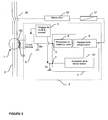
- FIG. in the form of a block diagram, a protection device comprising sensors current 1, a tripping circuit 4 as well as means for adjusting the fault current 7 and time delay thresholds 9.
- the current sensors 1 comprise a circuit measuring toroid magnetic 101 disposed around the conductors of the current lines 3 to protect. Thus, the current lines 3 form the primary winding of the toroid of measured.
- a secondary winding 102 is connected to an input circuit 6 of the processing unit 2. The secondary winding 102 supplied to the circuit 6 a signal representative of a differential current that can flow in the current lines Electric 3.
- the input circuit 6 then supplies a voltage signal Vm to the circuit of triggering 4 via a measurement input M.
- This first signal Vm is representative of the differential electric current measured by the current sensors 1.
- the voltage signal Vm also depends on the current threshold set with the means Fault current threshold setting 7.
- an output of the input circuit 6 is connected to a rectifier and peak detection circuit 8 which provides a rectified voltage at means of setting the delay time 9.
- the tripping circuit 4 can provide a order after a longer or shorter time.
- the means for adjusting the current threshold 7 fix the value of a second signal supplied to the trigger circuit 4 via an input of time delay T.
- This second signal Vt depending on the current threshold chosen is provided to timer cancellation control means 10. Following his value, this voltage Vt, modifies or does not modify the value of the delay previously fixed by timer setting means 9.
- the secondary circuit 102 of the measurement toroid is connected in parallel with a load resistor Rc of the input circuit 6.
- the load resistance Rc of the input circuit determines the maximum sensitivity of the processing unit 2 and, consequently, the minimum current threshold of the device protection. This threshold can be modified with the adjustment means 7.
- Two diodes 11 "head-to-tail" are placed in parallel with the Rc load resistor to protect the trigger circuit 4 from peaks of voltage observed at current sensors 1.
- the means for adjusting the current threshold 7 comprise switching means 22 having a common point C connected to a line of reference V0 or mass and connected to outputs, at least a first output of minimum delay selection being connected to the adjustment means of time delay to provide a minimum timing control signal, at the minus a second fault current threshold selection output being connected to at least one gauge change resistor 12.
- Said minimum timing selection output connected to the delay input T of the tripping circuit 4 is biased by a polarization line V2.
- said switching means 22 comprise a contact 21 can take at least two positions. Among these positions, minus a first position P1, it is possible to connect the selection output of minimum delay at the time delay input T of the trip circuit 4. According to the embodiment described, the contact 21 of the means of switching 22 is then in the position P1. Apart from the first position P1 which allows to ground the delay input T of the circuit of 4. Other positions P2, P3, P4 are used to connect resistors 12 of different values to be placed in parallel with the sensors of current 1 and the load resistor RC of the input circuit 6.
- the switching means 22 consist of a rotary control switch axial.
- said switch is set to put a change resistance of 12 gauge in parallel with the load resistor Rc. Equivalent resistance of the set is then lower and it takes a higher differential current for that the trigger circuit 4 can send an order. Each position of switch then allows to set a maximum value of differential current accepted and thus changes the current threshold.
- the timer setting means 9, as shown in FIG. 3, comprise a resistor 13 connected in series with a capacitor 14 connected to the circuit ground.
- the charging time of the capacitor delay 14 determines the duration of the delay. This charging time depends essentially on the values of the resistor 13 and the capacitor 14. According to this embodiment, a variable resistor 13 makes it possible to obtain the desired setting of the timer.
- the timer cancellation control means 10 comprise a comparator 15 fed between a voltage V2 and ground.
- the output voltage of said comparator controls the conduction or blocking of a 16.
- transistor 16 is connected in series with the delay capacitor 14 of the setting means of the delay 9.
- the transistor is placed between the capacitor 14 and the ground or the reference line V0 of the circuit.
- the capacitor 14 timer setting means 9 will be connected to the mass or so floating.
- the rectifier circuit and peak detector 8 comprises a rectifier alternation 17.
- an electronic rectifier is used without threshold consisting in particular of two operational amplifiers not shown.
- the rectifier is connected to a comparator 18 by a peak detector 19.
- comparator 18 is supplied between a voltage V2 and ground.
- the peak voltage is applied to one of the inputs of the comparator 18 in order to be compared to a reference voltage VR1.
- the value of the reference voltage is between the value V2 and zero. So, if the peak voltage applied on the positive terminal of the comparator 18 is greater than the reference voltage VR1, an output voltage is close to the voltage V2. In addition, if the peak voltage is less than the reference voltage VR1, the voltage at the output of the comparator 18 is zero.
- the output voltage of the comparator 18 is then applied to the means of setting the time delay 9.
- the trigger circuit 4 can send an order more or less quickly. If the value of the variable resistor 13 is small, the trigger circuit 4 reacts quickly. When resistance 13 is high, a significant delay occurs between the moment when the peak voltage is equal to the reference voltage and the moment when the trip circuit 4 sends a order.
- a comparator 20 identical to those previously described, is placed between the output of the timer setting means 9.
- the particularity of treatment unit 2 is more specifically the current threshold setting means 7 which comprise a switch 22 having a contact 21 which can take at least 2 positions.
- this switch 22 has the particularity of having at least one position, in particular the position P1, for which the value is set concomitantly of the minimum or reduced delay and the value of the fault current threshold.
- This setting of the value of the minimum or reduced delay is imposed regardless of the timing value initially set by the adjustment means 9.
- the contact 21 of the switch 22 is in position P1
- the differential current rating of fault is set to 30mA and the timer is forced to 0 seconds.
- This setting responds then to the normative requirements that the devices of differential protection for the protection of human beings force their timeout at 0 seconds for the minimum size of 30mA.
- the contact 21 of the switch 22 is placed on the position P1.
- the ground potential of point C of switch 22 is then applied to the level of the tripping input of the tripping circuit. 4.
- the voltage Vt applied to a first input of the comparator 15 means of cancellation command 10 is null. Knowing that the value of the voltage of reference VR2 applied to the second input of the comparator is included between 0 and V2, the value of the input voltage is then less than the voltage of reference VR2.
- the output voltage of the comparator 15 is then equal to 0.
- the transistor 16 is not controlled and is therefore not passing. It is equivalent to a open switch.
- the delay capacitor 14 of the adjustment means delay 9 is no longer connected to the ground, which has the effect of canceling the value of the delay.
- the cancellation control means 10 have therefore sent an order to cancel the timer value.
- the contact 21 of the switch 22 is then placed in a position different from that described above.
- the voltage applied to the timer input T of the circuit of trigger 4 is then different from zero. Input T is no longer connected to the line reference V0.
- the voltage Vt applied to the first input of the comparator 15 cancellation control means 10 is equal to V2.
- the voltage V2 is applied via the bias resistor R1.
- the value of the reference voltage VR2 applied to the second input of the comparator 15 being between 0 and V2, the output of the comparator 15 controls the base of the control transistor 16 and turns on said transistor.
- the transistor of command 16 is then equivalent to a closed switch.
- the capacitor of delay 14 of the timer setting means is therefore connected to the mass and participates fully in the value of the delay.
- the means of cancellation command of timer 10 did not send an order cancellation of the timeout value and are then without influence on the duration of the delay.
- the trigger 4 will send an order more or less quickly after the appearance of the fault current.
- the value of the timer is then selected in function of the value of the variable resistor 13 of the adjustment means correspondents.
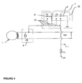
- gauge change resistors associated with different positions contact 21 of the switch 22 are respectively connected in series by measurement means 1.
- the minimum size corresponds to the position of the switch where none of said 12-gauge changeover resistors is shorted.
- the equivalent resistance across which the voltage Vm is measured is then maximum and corresponds to a maximum sensitivity.
- the equivalent load resistance is equal to the sum of all the resistances 12 mounted in series.
- the means of switching 22 may consist of a side-operated switch.
- the means for adjusting the 9, comprise a resistor 13 connected in series with a variable capacitor connected to the circuit ground.
- the capacitor of variable delay allows to obtain the desired setting of the delay.
- the transistor of control 16 can be connected in parallel with the variable resistor 13 of the timer setting means 9.
- the reference voltages of the inputs of the comparators VR1, VR2, VR3 can advantageously be of the same value and have a voltage between the voltage of the reference line V0 or the mass and the voltage supply or bias V2.
- the controlled switch function played by the bipolar transistor 16 can also be obtained by a field effect transistor (FET) or a relay.
- FET field effect transistor
- the present differential protection device is particularly intended for circuit breakers or electrical switches.
- the control command sent by the tripping circuit 4 is intended for a device for breaking the electric power lines 3.
- the order of command sent to the control relay 31 opens contacts 30 by via a control mechanism 32. Said contacts 30 are placed in series with electric current lines 3.
- a device according to the invention may be intended to measure polar currents in conductors of electric power lines. The torus measurement will then be replaced by current sensors placed respectively around each driver. A fault current signal differential is then reconstituted in a processing unit having means for adjusting the current threshold functioning as in the modes of embodiment described above.
Landscapes
- Engineering & Computer Science (AREA)
- Power Engineering (AREA)
- Emergency Protection Circuit Devices (AREA)
- Breakers (AREA)
- Closed-Circuit Television Systems (AREA)
- Testing, Inspecting, Measuring Of Stereoscopic Televisions And Televisions (AREA)
Abstract
Description
- des moyens de mesure de courant différentiel, et
- une unité de traitement comprenant des moyens de réglage du seuil de courant de défaut et des moyens de réglage d'une temporisation, l'unité de traitement étant connectée auxdits moyens de mesure pour recevoir un signal représentatif d'un courant différentiel.
- La figure 1 représente un schéma bloc général d'un dispositif de protection différentielle de type connu ;
- La figure 2 représente un schéma bloc général d'un dispositif de protection différentielle selon un mode de réalisation de l'invention ;
- La figure 3 représente un schéma bloc détaillé d'un dispositif de protection différentielle selon un mode de réalisation de l'invention ;
- La figure 4 représente une variante des moyens de réglage du seuil de courant selon un autre mode de réalisation de l'invention.
Claims (10)
- Dispositif de protection différentielle comportant :caractérisé en ce quedes moyens de mesure (1) de courant différentiel, etune unité de traitement (2) comprenant des moyens de réglage du seuil de courant de défaut (7) et des moyens de réglage d'une temporisation (9), l'unité de traitement étant connectée auxdits moyens de mesure (1) pour recevoir un signal représentatif d'un courant différentiel,
les moyens de réglage du seuil de courant de défaut (7) comportent des moyens de commutation (22) ayant un contact (21) pouvant prendre au moins deux positions, pour sélectionner un seuil de courant de défaut pour chacune des positions, et pour sélectionner pour une au moins desdites positions, une valeur minimale ou réduite de temporisation quel que soit le réglage initial des moyens de réglage de temporisation (9). - Dispositif de protection selon la revendication 1 caractérisé en ce que lesdits moyens de commutation (22) comporte un point commun (C) relié à une ligne de référence (V0) et relié à des sorties,au moins une première sortie de sélection de temporisation minimale étant connectée auxdits moyens de réglage de temporisation (9) pour fournir un signal de commande de temporisation minimale,au moins une seconde sortie de sélection de seuil de courant de défaut étant connectée à au moins une résistance de changement de calibre (12).
- Dispositif de protection selon la revendication 2 caractérisé en ce que ladite sortie de sélection de temporisation minimale est polarisée par une ligne de polarisation (V2).
- Dispositif de protection selon l'une quelconque des revendications 1 à 3 caractérisé en ce que les résistances de changement de calibre (12) sont connectées en parallèle avec les moyens de mesure de courant (1), à travers le contact (21) des moyens de commutation (22).
- Dispositif de protection selon l'une quelconque des revendications 1 à 3 caractérisé en ce que les résistances de changement de calibre (12) sont connectées en série avec les moyens de mesure de courant (1), à travers le contact (21) des moyens de commutation (22).
- Dispositif de protection selon l'une quelconque des revendications 1 à 5 caractérisé en ce lesdits moyens de commutation (22) sont constitués d'un commutateur rotatif à commande axiale.
- Dispositif de protection selon l'une quelconque des revendications 1 à 6 caractérisé en ce que les moyens de réglage du seuil de courant (7) sélectionnent ladite valeur minimale de la temporisation en fournissant un signal de commande de temporisation minimale (Vt) à des moyens d'annulation de la temporisation (10) de l'unité de traitement (2).
- Dispositif de protection selon la revendication 7 caractérisé en ce que les moyens de réglage de la temporisation (9) comprennent une résistance variable (13) montée en série avec un condensateur (14) relié à une ligne de référence (V0) et que les moyens d'annulation de la temporisation (10) commandent l'ouverture ou la fermeture de la liaison entre ledit condensateur et la ligne de référence (V0).
- Dispositif de protection selon les revendications 7 et 8 caractérisé en ce que les moyens d'annulation de temporisation (10) comportent une entrée (T) pour recevoir le signal de commande de temporisation minimale (Vt), des moyens de comparaison (15) pour comparer ledit signal de commande à un seuil de référence (VR1) et des moyens d'interruption (16) connectés en série avec le condensateur de temporisation (14) pour réduire ou annuler la temporisation d'un déclenchement.
- Disjoncteur comportant des contacts d'ouverture (30) reliés à des lignes de courant électrique (3) et un relais (31) pour commander l'ouverture desdits contacts (30) à travers un mécanisme (32) caractérisé en ce qu'il comporte un dispositif de protection différentielle selon l'une quelconque des revendications précédentes comportant, des moyens de mesure de courant différentiel (1) disposés sur lesdites lignes de courant (3), une unité de traitement (2) fournissant un signal de déclenchement auxdits relais si un défaut est détecté et des moyens de réglage du seuil de courant ayant une position pour sélectionner une valeur minimale de temporisation.
Applications Claiming Priority (2)
| Application Number | Priority Date | Filing Date | Title |
|---|---|---|---|
| FR0400605 | 2004-01-22 | ||
| FR0400605A FR2865582B1 (fr) | 2004-01-22 | 2004-01-22 | Dispositif de protection differentielle avec moyens de reglage simplifies des parametres de protection |
Publications (2)
| Publication Number | Publication Date |
|---|---|
| EP1557922A1 true EP1557922A1 (fr) | 2005-07-27 |
| EP1557922B1 EP1557922B1 (fr) | 2014-08-27 |
Family
ID=34630664
Family Applications (1)
| Application Number | Title | Priority Date | Filing Date |
|---|---|---|---|
| EP05354001.9A Expired - Lifetime EP1557922B1 (fr) | 2004-01-22 | 2005-01-06 | Dispositif de protection différentielle avec moyens de reglage simplifiés des paramètres de protection |
Country Status (6)
| Country | Link |
|---|---|
| US (1) | US20050162788A1 (fr) |
| EP (1) | EP1557922B1 (fr) |
| JP (1) | JP4472538B2 (fr) |
| CN (1) | CN100530879C (fr) |
| ES (1) | ES2522279T3 (fr) |
| FR (1) | FR2865582B1 (fr) |
Cited By (2)
| Publication number | Priority date | Publication date | Assignee | Title |
|---|---|---|---|---|
| EP1845548A3 (fr) * | 2006-04-13 | 2009-04-22 | ABB PATENT GmbH | Dispositif, circuit et procédé destinés à la surveillance de l'isolation et du raccordement à la terre dans un système informatique |
| FR3029350A1 (fr) * | 2014-12-01 | 2016-06-03 | Hager-Electro Sas | Dispositif de protection differentielle |
Families Citing this family (10)
| Publication number | Priority date | Publication date | Assignee | Title |
|---|---|---|---|---|
| CN101752146B (zh) * | 2008-12-02 | 2013-09-11 | 施耐德电器工业公司 | 提高微型断路器的电磁脱扣器整定电流稳定性的方法 |
| AT510330A2 (de) * | 2010-08-19 | 2012-03-15 | Eaton Gmbh | Schaltgerät |
| SG189580A1 (en) * | 2011-10-21 | 2013-05-31 | Schneider Electric South East Asia Hq Pte Ltd | An automatic configurable relay |
| CN102709033A (zh) * | 2012-01-04 | 2012-10-03 | 吴江市东泰电力特种开关有限公司 | 一种连续过渡有载分接开关 |
| DE102012024893B4 (de) * | 2012-12-20 | 2017-01-26 | Krohne Messtechnik Gmbh | Messanordnung zur Bestimmung einer Messgröße und Verfahren zur Erzeugung eines Ausgangssignals |
| GB2521872A (en) * | 2014-01-07 | 2015-07-08 | Tripco Ltd | An electrical fault protection device |
| US10502771B2 (en) * | 2016-01-29 | 2019-12-10 | Landis+Gyr Llc | Detecting current measurement tampering by current transformer parallel impedance |
| FR3072462B1 (fr) * | 2017-10-16 | 2020-05-22 | Schneider Electric Industries Sas | Dispositif de mesure de courant, procede de fabrication, module de protection et disjoncteur differentiel utilisant un tel dispositif de mesure de courant |
| CN112003246B (zh) * | 2020-07-30 | 2023-05-05 | 欣旺达惠州动力新能源有限公司 | 过流保护断路器 |
| WO2022136421A1 (fr) * | 2020-12-21 | 2022-06-30 | Siemens Aktiengesellschaft | Procédé et dispositif disjoncteur |
Citations (1)
| Publication number | Priority date | Publication date | Assignee | Title |
|---|---|---|---|---|
| EP0936716A1 (fr) * | 1998-02-11 | 1999-08-18 | Schneider Electric Sa | Dispositif de protection differentielle |
Family Cites Families (4)
| Publication number | Priority date | Publication date | Assignee | Title |
|---|---|---|---|---|
| US4833564A (en) * | 1987-09-24 | 1989-05-23 | Siemens Energy & Automation, Inc. | Current sensing relay circuit with adjustable sensitivity and tracking test circuit |
| FR2722622B1 (fr) * | 1994-07-18 | 1996-08-30 | Schneider Electric Sa | Declencheur electronique comportant au moins un organe de reglage |
| FR2751501B1 (fr) * | 1996-07-16 | 1999-04-30 | Schneider Electric Sa | Appareillage electrique comportant un dispositif de communication |
| FR2798524B1 (fr) * | 1999-09-13 | 2001-11-02 | Schneider Electric Ind Sa | Declencheur comportant une interface homme-machine amelioree et disjoncteur comportant un tel dispositif |
-
2004
- 2004-01-22 FR FR0400605A patent/FR2865582B1/fr not_active Expired - Fee Related
- 2004-12-29 US US11/023,410 patent/US20050162788A1/en not_active Abandoned
-
2005
- 2005-01-06 ES ES05354001.9T patent/ES2522279T3/es not_active Expired - Lifetime
- 2005-01-06 EP EP05354001.9A patent/EP1557922B1/fr not_active Expired - Lifetime
- 2005-01-21 JP JP2005014461A patent/JP4472538B2/ja not_active Expired - Lifetime
- 2005-01-24 CN CNB2005100056794A patent/CN100530879C/zh not_active Expired - Fee Related
Patent Citations (1)
| Publication number | Priority date | Publication date | Assignee | Title |
|---|---|---|---|---|
| EP0936716A1 (fr) * | 1998-02-11 | 1999-08-18 | Schneider Electric Sa | Dispositif de protection differentielle |
Cited By (3)
| Publication number | Priority date | Publication date | Assignee | Title |
|---|---|---|---|---|
| EP1845548A3 (fr) * | 2006-04-13 | 2009-04-22 | ABB PATENT GmbH | Dispositif, circuit et procédé destinés à la surveillance de l'isolation et du raccordement à la terre dans un système informatique |
| FR3029350A1 (fr) * | 2014-12-01 | 2016-06-03 | Hager-Electro Sas | Dispositif de protection differentielle |
| WO2016087768A1 (fr) * | 2014-12-01 | 2016-06-09 | Hager-Electro Sas (Société Par Actions Simplifiée) | Dispositif de protection différentielle |
Also Published As
| Publication number | Publication date |
|---|---|
| CN100530879C (zh) | 2009-08-19 |
| EP1557922B1 (fr) | 2014-08-27 |
| US20050162788A1 (en) | 2005-07-28 |
| ES2522279T3 (es) | 2014-11-14 |
| JP2005209652A (ja) | 2005-08-04 |
| CN1645702A (zh) | 2005-07-27 |
| JP4472538B2 (ja) | 2010-06-02 |
| FR2865582A1 (fr) | 2005-07-29 |
| FR2865582B1 (fr) | 2006-03-10 |
Similar Documents
| Publication | Publication Date | Title |
|---|---|---|
| EP0235479B1 (fr) | Déclencheur statique à circuit de test pour disjoncteur électrique | |
| EP0061364B1 (fr) | Disjoncteur basse tension multicalibre à déclencheur hybride | |
| EP1557922B1 (fr) | Dispositif de protection différentielle avec moyens de reglage simplifiés des paramètres de protection | |
| WO2003054895A1 (fr) | Procede pour determiner l'usure des contacts d'un appareil interrupteur | |
| EP0407310A1 (fr) | Déclencheur statique comportant un système de désensibilisation de la protection terre | |
| FR2863115A1 (fr) | Interrupteur de circuit en cas de defaut a la terre. | |
| EP4167261A1 (fr) | Dispositif de commutation électrique, système de commutation et procédé associés | |
| WO2015022329A1 (fr) | Dispositif de commutation et protection a distance de systemes electriques | |
| EP3479448B1 (fr) | Dispositif de coupure a semi-conducteurs | |
| EP0936716B1 (fr) | Dispositif de protection différentielle | |
| EP0570304B1 (fr) | Déclencheur électronique comportant un dispositif de correction | |
| FR3089053A1 (fr) | Dispositif de protection pour un circuit électrique, circuit électrique équipé d’un tel dispositif et procédé de protection d’un tel circuit électrique | |
| FR2643195A1 (fr) | Procede et dispositif de protection d'un circuit ou reseau electrique a l'aide d'un disjoncteur a courant differentiel | |
| EP3790034A1 (fr) | Module électronique auxiliaire de protection et dispositif de disjonction associé | |
| EP2693585B1 (fr) | Système de protection d'une pluralité de départs électriques contre des courts-circuits, et installation électrique comprenant un tel système de protection | |
| WO2022243464A1 (fr) | Dispositif de commutation électrique, système de commutation et procédé associés | |
| EP3977577B1 (fr) | Appareil de protection de ligne (l) electrique pour détecter un défaut de fuite, de court-circuit, de surintensité et d'arc | |
| EP4503083A1 (fr) | Dispositif de protection électrique configuré pour déterminer automatiquement une cause d'une ouverture d'un circuit électrique et procédé associé | |
| EP3420619A1 (fr) | Aéronef comprenant un réseau électrique à courant continu et un système de protection dudit réseau | |
| FR2733648A1 (fr) | Relais statique protege | |
| EP0320409A1 (fr) | Déclencheur statique à source auxiliaire | |
| FR3116392A1 (fr) | Appareillage de protection à coupure électronique | |
| EP4118670B1 (fr) | Dispositif d'interrupteur hybride et de commande | |
| FR2622368A1 (fr) | Interrupteur differentiel selectif a courant de defaut | |
| WO2024209145A1 (fr) | Système et méthode de protection d'un système électronique d'actionnement contre un sur-courant |
Legal Events
| Date | Code | Title | Description |
|---|---|---|---|
| PUAI | Public reference made under article 153(3) epc to a published international application that has entered the european phase |
Free format text: ORIGINAL CODE: 0009012 |
|
| AK | Designated contracting states |
Kind code of ref document: A1 Designated state(s): AT BE BG CH CY CZ DE DK EE ES FI FR GB GR HU IE IS IT LI LT LU MC NL PL PT RO SE SI SK TR |
|
| AX | Request for extension of the european patent |
Extension state: AL BA HR LV MK YU |
|
| 17P | Request for examination filed |
Effective date: 20051015 |
|
| AKX | Designation fees paid |
Designated state(s): AT BE BG CH CY CZ DE DK EE ES FI FR GB GR HU IE IS IT LI LT LU MC NL PL PT RO SE SI SK TR |
|
| RAP1 | Party data changed (applicant data changed or rights of an application transferred) |
Owner name: SCHNEIDER ELECTRIC INDUSTRIES SAS |
|
| GRAP | Despatch of communication of intention to grant a patent |
Free format text: ORIGINAL CODE: EPIDOSNIGR1 |
|
| INTG | Intention to grant announced |
Effective date: 20140526 |
|
| GRAS | Grant fee paid |
Free format text: ORIGINAL CODE: EPIDOSNIGR3 |
|
| GRAA | (expected) grant |
Free format text: ORIGINAL CODE: 0009210 |
|
| AK | Designated contracting states |
Kind code of ref document: B1 Designated state(s): AT BE BG CH CY CZ DE DK EE ES FI FR GB GR HU IE IS IT LI LT LU MC NL PL PT RO SE SI SK TR |
|
| REG | Reference to a national code |
Ref country code: GB Ref legal event code: FG4D Free format text: NOT ENGLISH |
|
| REG | Reference to a national code |
Ref country code: CH Ref legal event code: EP |
|
| REG | Reference to a national code |
Ref country code: AT Ref legal event code: REF Ref document number: 684919 Country of ref document: AT Kind code of ref document: T Effective date: 20140915 |
|
| REG | Reference to a national code |
Ref country code: IE Ref legal event code: FG4D Free format text: LANGUAGE OF EP DOCUMENT: FRENCH |
|
| REG | Reference to a national code |
Ref country code: DE Ref legal event code: R096 Ref document number: 602005044578 Country of ref document: DE Effective date: 20141009 |
|
| REG | Reference to a national code |
Ref country code: ES Ref legal event code: FG2A Ref document number: 2522279 Country of ref document: ES Kind code of ref document: T3 Effective date: 20141114 |
|
| REG | Reference to a national code |
Ref country code: AT Ref legal event code: MK05 Ref document number: 684919 Country of ref document: AT Kind code of ref document: T Effective date: 20140827 |
|
| REG | Reference to a national code |
Ref country code: LT Ref legal event code: MG4D |
|
| REG | Reference to a national code |
Ref country code: NL Ref legal event code: VDEP Effective date: 20140827 |
|
| PG25 | Lapsed in a contracting state [announced via postgrant information from national office to epo] |
Ref country code: GR Free format text: LAPSE BECAUSE OF FAILURE TO SUBMIT A TRANSLATION OF THE DESCRIPTION OR TO PAY THE FEE WITHIN THE PRESCRIBED TIME-LIMIT Effective date: 20141128 Ref country code: BG Free format text: LAPSE BECAUSE OF FAILURE TO SUBMIT A TRANSLATION OF THE DESCRIPTION OR TO PAY THE FEE WITHIN THE PRESCRIBED TIME-LIMIT Effective date: 20141127 Ref country code: FI Free format text: LAPSE BECAUSE OF FAILURE TO SUBMIT A TRANSLATION OF THE DESCRIPTION OR TO PAY THE FEE WITHIN THE PRESCRIBED TIME-LIMIT Effective date: 20140827 Ref country code: LT Free format text: LAPSE BECAUSE OF FAILURE TO SUBMIT A TRANSLATION OF THE DESCRIPTION OR TO PAY THE FEE WITHIN THE PRESCRIBED TIME-LIMIT Effective date: 20140827 Ref country code: PT Free format text: LAPSE BECAUSE OF FAILURE TO SUBMIT A TRANSLATION OF THE DESCRIPTION OR TO PAY THE FEE WITHIN THE PRESCRIBED TIME-LIMIT Effective date: 20141229 Ref country code: SE Free format text: LAPSE BECAUSE OF FAILURE TO SUBMIT A TRANSLATION OF THE DESCRIPTION OR TO PAY THE FEE WITHIN THE PRESCRIBED TIME-LIMIT Effective date: 20140827 |
|
| PG25 | Lapsed in a contracting state [announced via postgrant information from national office to epo] |
Ref country code: AT Free format text: LAPSE BECAUSE OF FAILURE TO SUBMIT A TRANSLATION OF THE DESCRIPTION OR TO PAY THE FEE WITHIN THE PRESCRIBED TIME-LIMIT Effective date: 20140827 Ref country code: IS Free format text: LAPSE BECAUSE OF FAILURE TO SUBMIT A TRANSLATION OF THE DESCRIPTION OR TO PAY THE FEE WITHIN THE PRESCRIBED TIME-LIMIT Effective date: 20141227 Ref country code: CY Free format text: LAPSE BECAUSE OF FAILURE TO SUBMIT A TRANSLATION OF THE DESCRIPTION OR TO PAY THE FEE WITHIN THE PRESCRIBED TIME-LIMIT Effective date: 20140827 |
|
| PG25 | Lapsed in a contracting state [announced via postgrant information from national office to epo] |
Ref country code: NL Free format text: LAPSE BECAUSE OF FAILURE TO SUBMIT A TRANSLATION OF THE DESCRIPTION OR TO PAY THE FEE WITHIN THE PRESCRIBED TIME-LIMIT Effective date: 20140827 |
|
| PG25 | Lapsed in a contracting state [announced via postgrant information from national office to epo] |
Ref country code: EE Free format text: LAPSE BECAUSE OF FAILURE TO SUBMIT A TRANSLATION OF THE DESCRIPTION OR TO PAY THE FEE WITHIN THE PRESCRIBED TIME-LIMIT Effective date: 20140827 Ref country code: DK Free format text: LAPSE BECAUSE OF FAILURE TO SUBMIT A TRANSLATION OF THE DESCRIPTION OR TO PAY THE FEE WITHIN THE PRESCRIBED TIME-LIMIT Effective date: 20140827 Ref country code: RO Free format text: LAPSE BECAUSE OF FAILURE TO SUBMIT A TRANSLATION OF THE DESCRIPTION OR TO PAY THE FEE WITHIN THE PRESCRIBED TIME-LIMIT Effective date: 20140827 Ref country code: SK Free format text: LAPSE BECAUSE OF FAILURE TO SUBMIT A TRANSLATION OF THE DESCRIPTION OR TO PAY THE FEE WITHIN THE PRESCRIBED TIME-LIMIT Effective date: 20140827 |
|
| REG | Reference to a national code |
Ref country code: DE Ref legal event code: R097 Ref document number: 602005044578 Country of ref document: DE |
|
| PG25 | Lapsed in a contracting state [announced via postgrant information from national office to epo] |
Ref country code: PL Free format text: LAPSE BECAUSE OF FAILURE TO SUBMIT A TRANSLATION OF THE DESCRIPTION OR TO PAY THE FEE WITHIN THE PRESCRIBED TIME-LIMIT Effective date: 20140827 |
|
| PG25 | Lapsed in a contracting state [announced via postgrant information from national office to epo] |
Ref country code: BE Free format text: LAPSE BECAUSE OF NON-PAYMENT OF DUE FEES Effective date: 20150131 |
|
| PLBE | No opposition filed within time limit |
Free format text: ORIGINAL CODE: 0009261 |
|
| STAA | Information on the status of an ep patent application or granted ep patent |
Free format text: STATUS: NO OPPOSITION FILED WITHIN TIME LIMIT |
|
| 26N | No opposition filed |
Effective date: 20150528 |
|
| REG | Reference to a national code |
Ref country code: CH Ref legal event code: PL |
|
| PG25 | Lapsed in a contracting state [announced via postgrant information from national office to epo] |
Ref country code: LU Free format text: LAPSE BECAUSE OF FAILURE TO SUBMIT A TRANSLATION OF THE DESCRIPTION OR TO PAY THE FEE WITHIN THE PRESCRIBED TIME-LIMIT Effective date: 20150106 |
|
| GBPC | Gb: european patent ceased through non-payment of renewal fee |
Effective date: 20150106 |
|
| PG25 | Lapsed in a contracting state [announced via postgrant information from national office to epo] |
Ref country code: MC Free format text: LAPSE BECAUSE OF FAILURE TO SUBMIT A TRANSLATION OF THE DESCRIPTION OR TO PAY THE FEE WITHIN THE PRESCRIBED TIME-LIMIT Effective date: 20140827 |
|
| PG25 | Lapsed in a contracting state [announced via postgrant information from national office to epo] |
Ref country code: LI Free format text: LAPSE BECAUSE OF NON-PAYMENT OF DUE FEES Effective date: 20150131 Ref country code: CH Free format text: LAPSE BECAUSE OF NON-PAYMENT OF DUE FEES Effective date: 20150131 Ref country code: GB Free format text: LAPSE BECAUSE OF NON-PAYMENT OF DUE FEES Effective date: 20150106 |
|
| REG | Reference to a national code |
Ref country code: IE Ref legal event code: MM4A |
|
| PG25 | Lapsed in a contracting state [announced via postgrant information from national office to epo] |
Ref country code: SI Free format text: LAPSE BECAUSE OF FAILURE TO SUBMIT A TRANSLATION OF THE DESCRIPTION OR TO PAY THE FEE WITHIN THE PRESCRIBED TIME-LIMIT Effective date: 20140827 |
|
| REG | Reference to a national code |
Ref country code: FR Ref legal event code: PLFP Year of fee payment: 12 |
|
| PG25 | Lapsed in a contracting state [announced via postgrant information from national office to epo] |
Ref country code: IE Free format text: LAPSE BECAUSE OF NON-PAYMENT OF DUE FEES Effective date: 20150106 |
|
| REG | Reference to a national code |
Ref country code: FR Ref legal event code: PLFP Year of fee payment: 13 |
|
| PG25 | Lapsed in a contracting state [announced via postgrant information from national office to epo] |
Ref country code: HU Free format text: LAPSE BECAUSE OF FAILURE TO SUBMIT A TRANSLATION OF THE DESCRIPTION OR TO PAY THE FEE WITHIN THE PRESCRIBED TIME-LIMIT; INVALID AB INITIO Effective date: 20050106 |
|
| PG25 | Lapsed in a contracting state [announced via postgrant information from national office to epo] |
Ref country code: TR Free format text: LAPSE BECAUSE OF FAILURE TO SUBMIT A TRANSLATION OF THE DESCRIPTION OR TO PAY THE FEE WITHIN THE PRESCRIBED TIME-LIMIT Effective date: 20140827 |
|
| REG | Reference to a national code |
Ref country code: FR Ref legal event code: PLFP Year of fee payment: 14 |
|
| PGFP | Annual fee paid to national office [announced via postgrant information from national office to epo] |
Ref country code: FR Payment date: 20230124 Year of fee payment: 19 Ref country code: ES Payment date: 20230228 Year of fee payment: 19 Ref country code: CZ Payment date: 20221230 Year of fee payment: 19 |
|
| PGFP | Annual fee paid to national office [announced via postgrant information from national office to epo] |
Ref country code: IT Payment date: 20230120 Year of fee payment: 19 Ref country code: DE Payment date: 20230127 Year of fee payment: 19 |
|
| PG25 | Lapsed in a contracting state [announced via postgrant information from national office to epo] |
Ref country code: CZ Free format text: LAPSE BECAUSE OF NON-PAYMENT OF DUE FEES Effective date: 20240106 |
|
| PG25 | Lapsed in a contracting state [announced via postgrant information from national office to epo] |
Ref country code: CZ Free format text: LAPSE BECAUSE OF NON-PAYMENT OF DUE FEES Effective date: 20240106 |
|
| REG | Reference to a national code |
Ref country code: DE Ref legal event code: R119 Ref document number: 602005044578 Country of ref document: DE |
|
| PG25 | Lapsed in a contracting state [announced via postgrant information from national office to epo] |
Ref country code: DE Free format text: LAPSE BECAUSE OF NON-PAYMENT OF DUE FEES Effective date: 20240801 |
|
| PG25 | Lapsed in a contracting state [announced via postgrant information from national office to epo] |
Ref country code: FR Free format text: LAPSE BECAUSE OF NON-PAYMENT OF DUE FEES Effective date: 20240131 |
|
| PG25 | Lapsed in a contracting state [announced via postgrant information from national office to epo] |
Ref country code: FR Free format text: LAPSE BECAUSE OF NON-PAYMENT OF DUE FEES Effective date: 20240131 Ref country code: DE Free format text: LAPSE BECAUSE OF NON-PAYMENT OF DUE FEES Effective date: 20240801 |
|
| PG25 | Lapsed in a contracting state [announced via postgrant information from national office to epo] |
Ref country code: IT Free format text: LAPSE BECAUSE OF NON-PAYMENT OF DUE FEES Effective date: 20240106 |
|
| REG | Reference to a national code |
Ref country code: ES Ref legal event code: FD2A Effective date: 20250226 |
|
| PG25 | Lapsed in a contracting state [announced via postgrant information from national office to epo] |
Ref country code: ES Free format text: LAPSE BECAUSE OF NON-PAYMENT OF DUE FEES Effective date: 20240107 |