EP1557731A1 - Liquid shut-off valve - Google Patents
Liquid shut-off valve Download PDFInfo
- Publication number
- EP1557731A1 EP1557731A1 EP20050001094 EP05001094A EP1557731A1 EP 1557731 A1 EP1557731 A1 EP 1557731A1 EP 20050001094 EP20050001094 EP 20050001094 EP 05001094 A EP05001094 A EP 05001094A EP 1557731 A1 EP1557731 A1 EP 1557731A1
- Authority
- EP
- European Patent Office
- Prior art keywords
- piston
- cup
- valve
- fluid
- outlet
- Prior art date
- Legal status (The legal status is an assumption and is not a legal conclusion. Google has not performed a legal analysis and makes no representation as to the accuracy of the status listed.)
- Granted
Links
Images


Classifications
-
- G—PHYSICS
- G05—CONTROLLING; REGULATING
- G05D—SYSTEMS FOR CONTROLLING OR REGULATING NON-ELECTRIC VARIABLES
- G05D9/00—Level control, e.g. controlling quantity of material stored in vessel
- G05D9/02—Level control, e.g. controlling quantity of material stored in vessel without auxiliary power
-
- H—ELECTRICITY
- H01—ELECTRIC ELEMENTS
- H01M—PROCESSES OR MEANS, e.g. BATTERIES, FOR THE DIRECT CONVERSION OF CHEMICAL ENERGY INTO ELECTRICAL ENERGY
- H01M10/00—Secondary cells; Manufacture thereof
- H01M10/34—Gastight accumulators
- H01M10/342—Gastight lead accumulators
-
- H—ELECTRICITY
- H01—ELECTRIC ELEMENTS
- H01M—PROCESSES OR MEANS, e.g. BATTERIES, FOR THE DIRECT CONVERSION OF CHEMICAL ENERGY INTO ELECTRICAL ENERGY
- H01M10/00—Secondary cells; Manufacture thereof
- H01M10/34—Gastight accumulators
- H01M10/345—Gastight metal hydride accumulators
-
- H—ELECTRICITY
- H01—ELECTRIC ELEMENTS
- H01M—PROCESSES OR MEANS, e.g. BATTERIES, FOR THE DIRECT CONVERSION OF CHEMICAL ENERGY INTO ELECTRICAL ENERGY
- H01M50/00—Constructional details or processes of manufacture of the non-active parts of electrochemical cells other than fuel cells, e.g. hybrid cells
- H01M50/30—Arrangements for facilitating escape of gases
- H01M50/308—Detachable arrangements, e.g. detachable vent plugs or plug systems
-
- H—ELECTRICITY
- H01—ELECTRIC ELEMENTS
- H01M—PROCESSES OR MEANS, e.g. BATTERIES, FOR THE DIRECT CONVERSION OF CHEMICAL ENERGY INTO ELECTRICAL ENERGY
- H01M50/00—Constructional details or processes of manufacture of the non-active parts of electrochemical cells other than fuel cells, e.g. hybrid cells
- H01M50/60—Arrangements or processes for filling or topping-up with liquids; Arrangements or processes for draining liquids from casings
- H01M50/609—Arrangements or processes for filling with liquid, e.g. electrolytes
- H01M50/627—Filling ports
-
- Y—GENERAL TAGGING OF NEW TECHNOLOGICAL DEVELOPMENTS; GENERAL TAGGING OF CROSS-SECTIONAL TECHNOLOGIES SPANNING OVER SEVERAL SECTIONS OF THE IPC; TECHNICAL SUBJECTS COVERED BY FORMER USPC CROSS-REFERENCE ART COLLECTIONS [XRACs] AND DIGESTS
- Y02—TECHNOLOGIES OR APPLICATIONS FOR MITIGATION OR ADAPTATION AGAINST CLIMATE CHANGE
- Y02E—REDUCTION OF GREENHOUSE GAS [GHG] EMISSIONS, RELATED TO ENERGY GENERATION, TRANSMISSION OR DISTRIBUTION
- Y02E60/00—Enabling technologies; Technologies with a potential or indirect contribution to GHG emissions mitigation
- Y02E60/10—Energy storage using batteries
-
- Y—GENERAL TAGGING OF NEW TECHNOLOGICAL DEVELOPMENTS; GENERAL TAGGING OF CROSS-SECTIONAL TECHNOLOGIES SPANNING OVER SEVERAL SECTIONS OF THE IPC; TECHNICAL SUBJECTS COVERED BY FORMER USPC CROSS-REFERENCE ART COLLECTIONS [XRACs] AND DIGESTS
- Y10—TECHNICAL SUBJECTS COVERED BY FORMER USPC
- Y10T—TECHNICAL SUBJECTS COVERED BY FORMER US CLASSIFICATION
- Y10T137/00—Fluid handling
- Y10T137/4673—Plural tanks or compartments with parallel flow
- Y10T137/4757—Battery or electrolytic cell replenishment
-
- Y—GENERAL TAGGING OF NEW TECHNOLOGICAL DEVELOPMENTS; GENERAL TAGGING OF CROSS-SECTIONAL TECHNOLOGIES SPANNING OVER SEVERAL SECTIONS OF THE IPC; TECHNICAL SUBJECTS COVERED BY FORMER USPC CROSS-REFERENCE ART COLLECTIONS [XRACs] AND DIGESTS
- Y10—TECHNICAL SUBJECTS COVERED BY FORMER USPC
- Y10T—TECHNICAL SUBJECTS COVERED BY FORMER US CLASSIFICATION
- Y10T137/00—Fluid handling
- Y10T137/7287—Liquid level responsive or maintaining systems
-
- Y—GENERAL TAGGING OF NEW TECHNOLOGICAL DEVELOPMENTS; GENERAL TAGGING OF CROSS-SECTIONAL TECHNOLOGIES SPANNING OVER SEVERAL SECTIONS OF THE IPC; TECHNICAL SUBJECTS COVERED BY FORMER USPC CROSS-REFERENCE ART COLLECTIONS [XRACs] AND DIGESTS
- Y10—TECHNICAL SUBJECTS COVERED BY FORMER USPC
- Y10T—TECHNICAL SUBJECTS COVERED BY FORMER US CLASSIFICATION
- Y10T137/00—Fluid handling
- Y10T137/7287—Liquid level responsive or maintaining systems
- Y10T137/7358—By float controlled valve
-
- Y—GENERAL TAGGING OF NEW TECHNOLOGICAL DEVELOPMENTS; GENERAL TAGGING OF CROSS-SECTIONAL TECHNOLOGIES SPANNING OVER SEVERAL SECTIONS OF THE IPC; TECHNICAL SUBJECTS COVERED BY FORMER USPC CROSS-REFERENCE ART COLLECTIONS [XRACs] AND DIGESTS
- Y10—TECHNICAL SUBJECTS COVERED BY FORMER USPC
- Y10T—TECHNICAL SUBJECTS COVERED BY FORMER US CLASSIFICATION
- Y10T137/00—Fluid handling
- Y10T137/7287—Liquid level responsive or maintaining systems
- Y10T137/7498—Barometric
Definitions
- This invention relates to automatic shut-off valves for controlling liquid flow to batteries for aqueous electrolyte replenishment.
- Automatic watering systems for batteries employ independent valves in each cell of the battery to control the flow of water into the cells for replenishing the aqueous electrolyte that is lost during battery charging.
- Such batteries typically comprise a casing containing a number of individual cells, each holding an electrolyte solution in which plates are immersed.
- Examples of batteries having an aqueous electrolyte include nickel-cadmium batteries or lead-acid type batteries. Oxygen and hydrogen gases are produced during charging as a result of electrolysis of the water. The electrolysis causes a loss of water from the electrolyte solution, and, as a result, such batteries require periodic replenishment of the lost water.
- valves It is advantageous for the valves to operate effectively across a wide range of water pressures. They should be sensitive enough to operate at low pressures of about 4 psi, but stable enough to operate at high pressures of about 50 psi.
- Valves currently in use for battery watering may be classified in one of two categories, i.e., hydrostatic or hydrodynamic.
- Hydrostatic valves typically rely on a float buoyed by the electrolyte to open and close the valve, while hydrodynamic valves rely on a venturi-based mechanism for actuation.
- Both types of valves can employ a positive stop configuration.
- Positive stop valves have a closing member, typically a piston, that moves within a pressurized chamber through which the water or other fluid flows. Upon actuation by the float or venturi mechanism, the piston engages with or disengages from a seat within the chamber to close and open the valve. In the positive stop configuration, the piston moves into the closed position with the water flow or pressure.
- Positive stop valves be they hydrostatic or hydrodynamic, suffer from the same disadvantage, in that hydrodynamic drag on the piston engendered as water flows through the valve can cause the piston to close the valve prematurely in response to the water flow or pressure, and not in response to the fluid level as intended.
- Positive stop valves in particular, tend to close prematurely when operated at high pressures which generate high drag forces on the piston and its actuating mechanism. This characteristic limits the range over which positive stop valves may be effectively employed to the lower pressures.
- the invention concerns a valve for controlling fluid flow, and particularly positive stop valves operable over a wide range of pressures and flow rates useful for automatic battery watering.
- the valve according to the invention comprises a chamber having a fluid inlet and a fluid outlet.
- a valve seat surrounds the outlet.
- a valve closing member is positioned within the chamber. The closing member is movable between a closed configuration in sealing engagement with the seat, thereby stopping flow of the fluid through the outlet, and an open position in spaced relation away from the seat.
- a biasing member is engaged with the closing member. The biasing member biases the closing member into the open configuration.
- An actuator is engaged with the closing member. The actuator is adapted to apply a force moving the closing member into the closed configuration.
- a first deflector surface is positioned within the chamber between the inlet and the closing member. The first deflector surface deflects the flow of the fluid around the closing member to prevent flow of the fluid from engaging and moving the closing member into the closed configuration.
- the valve according to the invention may also include a second deflector surface positioned within the chamber downstream of the valve closing member.
- the second deflector surface deflects the flow of the fluid against the closing member so as to further bias the closing member into the open configuration.
- the second deflector surface is positioned surrounding the seat in facing relation with the closing member.
- the actuator comprises a cup having a first end positioned outside of the chamber adjacent to the outlet. A second, open end of the cup is positioned distally to the outlet. A nozzle extends from the outlet into the cup through an opening in the first end. The cup is slidably movable along the nozzle. A tether having a first end attached to the cup extends through the nozzle. A second end of the tether is attached to the closing member. Flow of fluid through the nozzle creates a partial vacuum within the cup when the open end engages a fluid surface. The vacuum draw the cup along the nozzle away from the chamber, and the tether draws the closing member into the closed configuration in sealing engagement with the seat, thereby halting the flow of fluid through the chamber.
- the actuating member comprises a float positioned outside of the chamber.
- a link member attaches the float to the closing member.
- the float when buoyantly supported by the electrolyte or other fluid, applies a force, by virtue of its buoyancy, to the closing member through the link member. The force moves the closing member into the closed configuration.
- the invention also includes a battery incorporating a valve as described above.
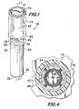
- FIG 1 shows an embodiment of a hydrodynamic valve 10 according to the invention.
- Valve 10 comprises a chamber 12, preferably in the form of an elongated cylinder.
- a cap 14 is positioned at one end of chamber 12, the cap having one or more fluid inlets in the form of slots 16 allowing fluid flow into the chamber.
- a fluid outlet 18 is positioned at the opposite end of chamber 12.
- a valve seat 20 surrounds the outlet, and as shown in Figure 2, a nozzle 22 extends from the outlet.
- a valve closing member in the form of a piston 24 is positioned within the chamber 12. Piston 24 is slidably movable within chamber 12 between an open position (shown in Figure 2) where it is in spaced relation away from seat 20, and a closed position (see Figure 3) where it is engaged in sealing relation with the seat.
- a biasing member preferably a spring 26, is attached between the cap 14 and the piston.
- Spring 26 biases the piston into the open configuration.
- An actuator preferably in the form of an elongated cylindrical cup 28, is located at the outlet end of the chamber 12. Cup 28 is coaxially aligned with chamber 12 and has an opening 30 in one end through which nozzle 22 passes. The opposite end 32 of cup 28 is open.
- a tether 34 has one end 36 attached to the cup 28, preferably near the open end 32. The other end 38 is attached to the piston 24. As described in detail below, the cup is slidably movable along the nozzle 22 and acts as an actuator to pull the piston from the open to the closed position against the biasing action of spring 26 through the tether 34.
- a deflector surface 40 is positioned within the chamber 12 between the inlet slots 16 and the outlet 18.
- Deflector surface 40 may have any practical shape suitable for a particular valve design, and in this embodiment, the deflector surface preferably comprises an elongated cylinder 42 positioned within chamber 12 and extending from cap 14. Inner cylinder 42 surrounds the piston 24 and preferably is coaxially aligned with the outer cylinder forming the chamber 12. As shown in Figures 2 and 4, this configuration produces an annular duct 44 providing fluid communication between the inlet slots 16 and the outlet 18.
- the deflector surface 40 functions to deflect the flow of fluid around the piston 24 and thereby prevent hydrodynamic drag on the piston by high pressure/high flow rate fluid flows through chamber 12. Thus, there is less tendency for the piston to close prematurely in response to the fluid pressure or flow.
- a second deflector surface 46 is positioned downstream of the piston 24.
- the second deflector surface is formed by the end 48 of chamber 12 that surrounds seat 20.
- the surface may be flat as shown or may be curved or otherwise shaped so as to provide hydrodynamic enhancements to the fluid flow.
- the second deflector surface 46 directs a portion of the fluid flow through the chamber against the piston 24 to provide dynamic fluid biasing of the piston as described below.
- valve 10 is shown positioned within a battery cell 50 having an aqueous electrolyte 52.
- a fitting 54 connected to a water source (not shown) is attachable to the valve 10 and supplies water 56 to the cell through valve.
- Water 56 flows into the valve through inlet slots 16 and through the annular duct 44, the water being deflected around the piston 24 by the surrounding deflector surface 40 (cylinder 42).
- the water 56 impinges on the second deflector surface 46 at the end 48 of chamber 12 and a portion of the flow 58 is deflected toward the piston 24.
- the remainder of the flow 60 exits through nozzle 22 into cup 28 where it enters battery cell 50 to replenish water lost to electrolysis during battery charging.
- the effect of the pressure and flow impingement on the piston is equivalent to having a higher biasing force on the piston at high pressures and flow rates when the pressure and momentum changes will be highest, but a lower biasing force on the piston, due mainly only to the spring 26, during low pressure and low flow rates.
- This renders the valve very sensitive at low pressure and flow rates and, in conjunction with the effect of the deflector surface 40, provides great stability preventing premature closure of the valve at high pressures and flow rates.
- Laboratory test results show that the ratio of high to low pressure that the valve can accommodate increases from about 6 to 1 to about 20 to 1, better than a three fold increase in the pressure range.
- the portion 60 of the water flow that exits through nozzle 22 works in conjunction with the actuator cup 28 to close the valve.
- Water 60 fills the cell 50 and the level of the electrolyte 52 rises until it contacts and seals the open end 32 of the cup.
- Continued flow of water through nozzle 22 draws a vacuum within the cup 28. This allows gas pressure on the outside surface 28a of the closed end of cup 28 to force the cup downwardly into the electrolyte as shown in Figure 3.
- Motion of the cup 28 pulls the tether 34, drawing the piston 24 into engagement with the seat 20 thereby halting the flow of water through the valve 10.
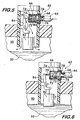
- FIGS 5 and 6 show an example of a hydrostatic valve embodiment 62 according to the invention.
- Valve 62 is mounted in fluid communication with a battery cell 50 and a conduit 64 connectable to a water source (not shown).
- Valve 62 comprises a chamber 66 having an inlet 68 connected to the conduit 64 and an outlet 70 in fluid communication with cell 50.
- a seat 72 surrounds the outlet 70.
- a valve closing member, preferably a piston 74 is movably mounted within the chamber. The piston may move between an open position in spaced relation away from seat 72 ( Figure 5), and a closed position wherein the piston is engaged in sealing relation with the seat ( Figure 6).
- the piston 74 slides within a cylinder 76 positioned between the inlet 68 and the outlet 70.
- the end 78 of cylinder 76 that faces the inlet is closed, thus forming a deflector surface that deflects the water flow 80 around the piston and prevents the generation of hydrodynamic drag on the piston that would otherwise tend to force it into the closed position regardless of the fluid level within the cell 50.
- a second deflector surface 73 is positioned within chamber 66. Deflector surface 73 faces piston 74 and, as described previously, deflects a portion of the water flow 80 against the piston to augment the biasing of the piston in the open position shown. Again, deflector surface 73 may be shaped to enhance the fluid flow against the piston.
- An actuator in the form of a float 82 is buoyantly supportable by the electrolyte 52 within cell 50.
- Float 82 is connected to piston 74 through a pivoting link member 84.
- Weight of the float 82 acting through the link member 84 applies a force to piston 74 pushing it away from engagement with seat 72, opening the valve 62 and allowing water 80 to flow into the cell 50.
- the float does not have to push the piston 74 against the flow of water through the chamber 68, enabling the float to be lighter and thus more responsive that if it had to open the valve against the water flow.
- Positive stop valves according to the invention can be operated over greater pressure ranges more reliably due to the presence of the deflector surface that deflects the flow of fluid around the valve closing member, thereby virtually eliminating hydrodynamic drag on the piston that would otherwise tend to close the valve regardless of the desired fluid level.
- the addition of a second deflector surface downstream of the valve closing member provides further dynamic biasing augmenting the forces that keep the valve in the open position. These forces are greatest when they are most needed, i.e., under high pressure and high flow rates that would otherwise engender premature valve closing.
Landscapes
- Chemical & Material Sciences (AREA)
- Chemical Kinetics & Catalysis (AREA)
- Electrochemistry (AREA)
- General Chemical & Material Sciences (AREA)
- Engineering & Computer Science (AREA)
- Manufacturing & Machinery (AREA)
- Physics & Mathematics (AREA)
- General Physics & Mathematics (AREA)
- Automation & Control Theory (AREA)
- Lift Valve (AREA)
- Fluid-Driven Valves (AREA)
- Filling, Topping-Up Batteries (AREA)
- Float Valves (AREA)
Abstract
Description
- This invention relates to automatic shut-off valves for controlling liquid flow to batteries for aqueous electrolyte replenishment.
- Automatic watering systems for batteries employ independent valves in each cell of the battery to control the flow of water into the cells for replenishing the aqueous electrolyte that is lost during battery charging. Such batteries typically comprise a casing containing a number of individual cells, each holding an electrolyte solution in which plates are immersed. Examples of batteries having an aqueous electrolyte include nickel-cadmium batteries or lead-acid type batteries. Oxygen and hydrogen gases are produced during charging as a result of electrolysis of the water. The electrolysis causes a loss of water from the electrolyte solution, and, as a result, such batteries require periodic replenishment of the lost water.
- It is advantageous for the valves to operate effectively across a wide range of water pressures. They should be sensitive enough to operate at low pressures of about 4 psi, but stable enough to operate at high pressures of about 50 psi.
- Valves currently in use for battery watering may be classified in one of two categories, i.e., hydrostatic or hydrodynamic. Hydrostatic valves typically rely on a float buoyed by the electrolyte to open and close the valve, while hydrodynamic valves rely on a venturi-based mechanism for actuation. Both types of valves can employ a positive stop configuration. Positive stop valves have a closing member, typically a piston, that moves within a pressurized chamber through which the water or other fluid flows. Upon actuation by the float or venturi mechanism, the piston engages with or disengages from a seat within the chamber to close and open the valve. In the positive stop configuration, the piston moves into the closed position with the water flow or pressure. Positive stop valves, be they hydrostatic or hydrodynamic, suffer from the same disadvantage, in that hydrodynamic drag on the piston engendered as water flows through the valve can cause the piston to close the valve prematurely in response to the water flow or pressure, and not in response to the fluid level as intended. Positive stop valves in particular, tend to close prematurely when operated at high pressures which generate high drag forces on the piston and its actuating mechanism. This characteristic limits the range over which positive stop valves may be effectively employed to the lower pressures. There is clearly a need for a valve that can operate over a large pressure range, encompassing both high and low pressures and flow rates, without premature closing due to high hydrodynamic drag.
- The invention concerns a valve for controlling fluid flow, and particularly positive stop valves operable over a wide range of pressures and flow rates useful for automatic battery watering. The valve according to the invention comprises a chamber having a fluid inlet and a fluid outlet. A valve seat surrounds the outlet. A valve closing member is positioned within the chamber. The closing member is movable between a closed configuration in sealing engagement with the seat, thereby stopping flow of the fluid through the outlet, and an open position in spaced relation away from the seat. A biasing member is engaged with the closing member. The biasing member biases the closing member into the open configuration. An actuator is engaged with the closing member. The actuator is adapted to apply a force moving the closing member into the closed configuration. A first deflector surface is positioned within the chamber between the inlet and the closing member. The first deflector surface deflects the flow of the fluid around the closing member to prevent flow of the fluid from engaging and moving the closing member into the closed configuration.
- The valve according to the invention may also include a second deflector surface positioned within the chamber downstream of the valve closing member. The second deflector surface deflects the flow of the fluid against the closing member so as to further bias the closing member into the open configuration. Preferably the second deflector surface is positioned surrounding the seat in facing relation with the closing member.
- In one hydrodynamic embodiment of the valve, the actuator comprises a cup having a first end positioned outside of the chamber adjacent to the outlet. A second, open end of the cup is positioned distally to the outlet. A nozzle extends from the outlet into the cup through an opening in the first end. The cup is slidably movable along the nozzle. A tether having a first end attached to the cup extends through the nozzle. A second end of the tether is attached to the closing member. Flow of fluid through the nozzle creates a partial vacuum within the cup when the open end engages a fluid surface. The vacuum draw the cup along the nozzle away from the chamber, and the tether draws the closing member into the closed configuration in sealing engagement with the seat, thereby halting the flow of fluid through the chamber.
- In another hydrostatic embodiment of the valve, the actuating member comprises a float positioned outside of the chamber. A link member attaches the float to the closing member. The float, when buoyantly supported by the electrolyte or other fluid, applies a force, by virtue of its buoyancy, to the closing member through the link member. The force moves the closing member into the closed configuration.
- The invention also includes a battery incorporating a valve as described above.
-
- Figure 1 is a perspective view of an embodiment of a valve according to the invention;
- Figures 2 and 3 are longitudinal sectional views taken at line 2-2 of Figure 1 depicting a portion of a battery cell using the valve shown in Figure 1;
- Figure 4 is a cross-sectional view taken at line 4-4 of Figure 2; and
- Figures 5 and 6 are longitudinal sectional views of a portion of a battery cell using another embodiment of a valve according to the invention.
-
- Figure 1 shows an embodiment of a
hydrodynamic valve 10 according to the invention.Valve 10 comprises achamber 12, preferably in the form of an elongated cylinder. Acap 14 is positioned at one end ofchamber 12, the cap having one or more fluid inlets in the form ofslots 16 allowing fluid flow into the chamber. Afluid outlet 18 is positioned at the opposite end ofchamber 12. Avalve seat 20 surrounds the outlet, and as shown in Figure 2, anozzle 22 extends from the outlet. A valve closing member in the form of apiston 24 is positioned within thechamber 12. Piston 24 is slidably movable withinchamber 12 between an open position (shown in Figure 2) where it is in spaced relation away fromseat 20, and a closed position (see Figure 3) where it is engaged in sealing relation with the seat. A biasing member, preferably aspring 26, is attached between thecap 14 and the piston.Spring 26 biases the piston into the open configuration. An actuator, preferably in the form of an elongatedcylindrical cup 28, is located at the outlet end of thechamber 12. Cup 28 is coaxially aligned withchamber 12 and has an opening 30 in one end through whichnozzle 22 passes. Theopposite end 32 ofcup 28 is open. Atether 34 has oneend 36 attached to thecup 28, preferably near theopen end 32. Theother end 38 is attached to thepiston 24. As described in detail below, the cup is slidably movable along thenozzle 22 and acts as an actuator to pull the piston from the open to the closed position against the biasing action ofspring 26 through thetether 34. - As shown in Figure 1, a
deflector surface 40 is positioned within thechamber 12 between theinlet slots 16 and theoutlet 18.Deflector surface 40 may have any practical shape suitable for a particular valve design, and in this embodiment, the deflector surface preferably comprises anelongated cylinder 42 positioned withinchamber 12 and extending fromcap 14.Inner cylinder 42 surrounds thepiston 24 and preferably is coaxially aligned with the outer cylinder forming thechamber 12. As shown in Figures 2 and 4, this configuration produces anannular duct 44 providing fluid communication between theinlet slots 16 and theoutlet 18. Thedeflector surface 40 functions to deflect the flow of fluid around thepiston 24 and thereby prevent hydrodynamic drag on the piston by high pressure/high flow rate fluid flows throughchamber 12. Thus, there is less tendency for the piston to close prematurely in response to the fluid pressure or flow. - As shown in Figure 2, a
second deflector surface 46 is positioned downstream of thepiston 24. In this embodiment, the second deflector surface is formed by theend 48 ofchamber 12 that surroundsseat 20. The surface may be flat as shown or may be curved or otherwise shaped so as to provide hydrodynamic enhancements to the fluid flow. Thesecond deflector surface 46 directs a portion of the fluid flow through the chamber against thepiston 24 to provide dynamic fluid biasing of the piston as described below. - Operation of the
valve 10 is described with reference to Figures 2 and 3. In Figure 2,valve 10 is shown positioned within abattery cell 50 having anaqueous electrolyte 52. A fitting 54 connected to a water source (not shown) is attachable to thevalve 10 and supplies water 56 to the cell through valve.Water 56 flows into the valve throughinlet slots 16 and through theannular duct 44, the water being deflected around thepiston 24 by the surrounding deflector surface 40 (cylinder 42). Thewater 56 impinges on thesecond deflector surface 46 at theend 48 ofchamber 12 and a portion of theflow 58 is deflected toward thepiston 24. The remainder of theflow 60 exits throughnozzle 22 intocup 28 where it entersbattery cell 50 to replenish water lost to electrolysis during battery charging. - The water flow slows as it exits the
annular duct 44 due to the sudden increase in cross sectional area of thechamber 12. By Bernoulli's principle, this causes a region of higher pressure to form beneath the piston. The higher pressure acts to augment the biasing force ofspring 26. The greater the rate of flow, the higher the pressure in this region. Furthermore, the portion of theflow 58 that is deflected by thesecond deflector surface 46 experiences a change in momentum that directs theflow portion 58 against the piston, further biasing it in the open position. This dynamic biasing force also increases with increasing pressure and flow rate. The effect of the pressure and flow impingement on the piston is equivalent to having a higher biasing force on the piston at high pressures and flow rates when the pressure and momentum changes will be highest, but a lower biasing force on the piston, due mainly only to thespring 26, during low pressure and low flow rates. This renders the valve very sensitive at low pressure and flow rates and, in conjunction with the effect of thedeflector surface 40, provides great stability preventing premature closure of the valve at high pressures and flow rates. Laboratory test results show that the ratio of high to low pressure that the valve can accommodate increases from about 6 to 1 to about 20 to 1, better than a three fold increase in the pressure range. - The
portion 60 of the water flow that exits throughnozzle 22 works in conjunction with theactuator cup 28 to close the valve.Water 60 fills thecell 50 and the level of theelectrolyte 52 rises until it contacts and seals theopen end 32 of the cup. Continued flow of water throughnozzle 22 draws a vacuum within thecup 28. This allows gas pressure on theoutside surface 28a of the closed end ofcup 28 to force the cup downwardly into the electrolyte as shown in Figure 3. Motion of thecup 28 pulls thetether 34, drawing thepiston 24 into engagement with theseat 20 thereby halting the flow of water through thevalve 10. - Figures 5 and 6 show an example of a
hydrostatic valve embodiment 62 according to the invention.Valve 62 is mounted in fluid communication with abattery cell 50 and aconduit 64 connectable to a water source (not shown).Valve 62 comprises achamber 66 having aninlet 68 connected to theconduit 64 and anoutlet 70 in fluid communication withcell 50. Aseat 72 surrounds theoutlet 70. A valve closing member, preferably apiston 74 is movably mounted within the chamber. The piston may move between an open position in spaced relation away from seat 72 (Figure 5), and a closed position wherein the piston is engaged in sealing relation with the seat (Figure 6). Preferably, thepiston 74 slides within acylinder 76 positioned between theinlet 68 and theoutlet 70. Theend 78 ofcylinder 76 that faces the inlet is closed, thus forming a deflector surface that deflects thewater flow 80 around the piston and prevents the generation of hydrodynamic drag on the piston that would otherwise tend to force it into the closed position regardless of the fluid level within thecell 50. - A
second deflector surface 73 is positioned withinchamber 66.Deflector surface 73 facespiston 74 and, as described previously, deflects a portion of thewater flow 80 against the piston to augment the biasing of the piston in the open position shown. Again,deflector surface 73 may be shaped to enhance the fluid flow against the piston. - An actuator in the form of a
float 82 is buoyantly supportable by theelectrolyte 52 withincell 50.Float 82 is connected topiston 74 through apivoting link member 84. Weight of thefloat 82 acting through thelink member 84 applies a force topiston 74 pushing it away from engagement withseat 72, opening thevalve 62 and allowingwater 80 to flow into thecell 50. Because of the presence of the deflectingsurface 78 the float does not have to push thepiston 74 against the flow of water through thechamber 68, enabling the float to be lighter and thus more responsive that if it had to open the valve against the water flow. - As shown in Figure 6, when the
electrolyte 52 reaches the desired level thefloat 82 is buoyantly supported and exerts a force onpiston 74 throughlink member 84 that closes the valve by engaging thepiston 74 with theseat 72, thereby halting the flow of water to the cell. - Positive stop valves according to the invention, whether hydrodynamic or hydrostatic in design, can be operated over greater pressure ranges more reliably due to the presence of the deflector surface that deflects the flow of fluid around the valve closing member, thereby virtually eliminating hydrodynamic drag on the piston that would otherwise tend to close the valve regardless of the desired fluid level. In hydrodynamic valves, the addition of a second deflector surface downstream of the valve closing member provides further dynamic biasing augmenting the forces that keep the valve in the open position. These forces are greatest when they are most needed, i.e., under high pressure and high flow rates that would otherwise engender premature valve closing.
Claims (20)
- A valve for controlling fluid flow, said valve comprising:a chamber having a fluid inlet and a fluid outlet;a valve seat surrounding said outlet;a valve closing member positioned within said chamber, said closing member being movable between a closed configuration in sealing engagement with said seat thereby stopping flow of said fluid through said outlet, and an open position in spaced relation away from said seat;a biasing member engaged with said closing member, said biasing member biasing said closing member into said open configuration;an actuator engaged with said closing member, said actuator adapted to apply a force moving said closing member into said closed configuration; anda first deflector surface positioned within said chamber between said inlet and said closing member, said first deflector surface deflecting the flow of said fluid around said closing member to prevent flow of said fluid from engaging and moving said closing member into said closed configuration.
- A valve according to Claim 1, further comprising a second deflector surface positioned within said chamber downstream of said valve closing member, said second deflector surface deflecting the flow of said fluid against said closing member so as to further bias said closing member into said open configuration.
- A valve according to Claim 2, wherein said second deflector surface is positioned surrounding said seat in facing relation with said closing member.
- A valve according to Claim 1, wherein said actuator comprises:a cup having a first end positioned outside of said chamber adjacent to said outlet and a second, open end, positioned distally to said outlet, a nozzle extending from said outlet into said cup through an opening in said first end, said cup being slidably movable along said nozzle; anda tether having a first end attached to said cup, said tether extending through said nozzle and having a second end attached to said closing member, flow of fluid through said nozzle creating a partial vacuum within said cup when said open end engages a fluid surface, said vacuum drawing said cup along said nozzle away from said chamber, said tether drawing said closing member into said closed configuration in sealing engagement with said seat, thereby halting the flow of fluid through said chamber.
- A valve according to Claim 4, wherein said cup comprises an elongated cylinder.
- A valve according to Claim 1, wherein:said chamber comprises an elongated outer cylinder, said inlet and outlet being positioned at opposite ends thereof;said first deflector surface comprises an inner cylinder positioned within said outer cylinder, said inner and outer cylinders being substantially lengthwise aligned and cooperating to form therebetween a duct, said duct being in fluid communication with said inlet and said outlet;said closing member comprises a piston positioned within said inner cylinder, said fluid flowing through said duct around said piston; andsaid biasing member comprises a spring positioned within said inner cylinder, said spring being attached between said inner cylinder and said piston and biasing said piston into said open configuration.
- A valve according to Claim 6, wherein said inner cylinder is coaxially aligned within said outer cylinder, said duct therebetween having an annular cross section.
- A valve according to Claim 1, wherein said actuating member comprises:a float positioned outside of said chamber; anda link member attaching said float to said closing member, said float, when buoyantly supported, applying a force, by virtue of its buoyancy, to said closing member through said link member, said force moving said closing member into said closed configuration.
- A valve according to Claim 8, wherein said biasing member comprises said float and said link member, said float, when unsupported, applying a force, by virtue of its weight, to said closing member through said link member, said force biasing said closing member into said open configuration.
- A valve for controlling fluid flow, said valve comprising:an elongated outer cylinder having an inlet at one end and an outlet at an opposite end;a nozzle in fluid communication with said outlet and projecting from said opposite end;an inner cylinder positioned within said outer cylinder, said inner cylinder being substantially lengthwise aligned with said outer cylinder, said cylinders cooperating to define a duct therebetween, said duct being in fluid communication with said inlet and said outlet;a valve seat positioned within said outer cylinder downstream of said inner cylinder;a piston positioned within said inner cylinder, said piston being reciprocally movable between a closed configuration wherein said piston sealingly engages said seat thereby preventing flow of said fluid through said outlet, and an open configuration wherein said piston is in spaced relation away from said seat;a biasing member positioned within said inner cylinder for biasing said piston into said open configuration;a cup having a first end positioned outside of said outer cylinder adjacent to said outlet and a second, open end, positioned distally to said outlet, said nozzle extending into said cup through an opening in said first end, said cup being slidably movable along said nozzle; anda tether having a first end attached to said cup, said tether extending through said nozzle and having a second end attached to said piston, flow of fluid entering said duct through said inlet and exiting said duct through said nozzle creating a partial vacuum within said cup when said open end engages a fluid surface, said vacuum drawing said cup along said nozzle away from said outer cylinder, said tether drawing said piston into said closed configuration in sealing engagement with said seat, thereby halting the flow of fluid through said valve.
- A valve according to Claim 10, wherein said inner and outer cylinders are co-axially arranged so that said duct has an annular cross section.
- A valve according to Claim 10, further comprising a fluid deflecting surface positioned in spaced apart relation to said inner cylinder and in facing relation with said piston, said deflecting surface deflecting fluid flow through said duct against said piston thereby further biasing said piston into said open configuration.
- A valve according to Claim 12, wherein said deflecting surface is substantially flat and oriented substantially perpendicular to said duct.
- A valve according to Claim 10, wherein said biasing member comprises a spring.
- A valve according to Claim 10, wherein said cup comprises an elongated cylinder.
- A battery having an aqueous electrolyte, a cell of said battery having a valve positioned in a vent port for controlling flow of water to said cell for replenishment of said electrolyte, said valve being connectable to a source of water and comprising:an elongated outer cylinder having an inlet at one end and an outlet at an opposite end;a nozzle in fluid communication with said outlet and projecting from said opposite end;an inner cylinder positioned within said outer cylinder, said inner cylinder being substantially lengthwise aligned with said outer cylinder, said cylinders cooperating to define a duct therebetween, said duct being in fluid communication with said inlet and said outlet;a valve seat positioned within said outer cylinder downstream of said inner cylinder;a piston positioned within said inner cylinder, said piston being reciprocally movable between a closed configuration wherein said piston sealingly engages said seat thereby preventing flow of said water through said outlet, and an open configuration wherein said piston is in spaced relation away from said seat;a biasing member positioned within said inner cylinder for biasing said piston into said open configuration;a cup having a first end positioned outside of said outer cylinder adjacent to said outlet and a second, open end, positioned distally to said outlet, said nozzle extending into said cup through an opening in said first end, said cup being slidably movable along said nozzle to engage said electrolyte within said cell; anda tether having a first end attached to said cup, said tether extending through said nozzle and having a second end attached to said piston, flow of water entering said duct through said inlet and exiting said duct through said nozzle creating a partial vacuum within said cup when said open end engages said electrolyte within said cell, said vacuum drawing said cup along said nozzle away from said chamber, said tether drawing said piston into said closed configuration in sealing engagement with said seat, thereby halting the flow of water through said valve into said cell.
- A valve according to Claim 16, wherein said inner and outer cylinders are co-axially arranged so that said duct has an annular cross section.
- A valve according to Claim 16, further comprising a fluid deflecting surface positioned in spaced apart relation to said inner cylinder and in facing relation with said piston, said deflecting surface deflecting fluid flow through said duct against said piston thereby further biasing said piston into said open configuration.
- A valve according to Claim 18, wherein said deflecting surface is substantially flat and oriented substantially perpendicular to said duct.
- A valve according to Claim 16, wherein said cup comprises an elongated cylinder.
Applications Claiming Priority (2)
| Application Number | Priority Date | Filing Date | Title |
|---|---|---|---|
| US53769204P | 2004-01-20 | 2004-01-20 | |
| US537692P | 2004-01-20 |
Publications (2)
| Publication Number | Publication Date |
|---|---|
| EP1557731A1 true EP1557731A1 (en) | 2005-07-27 |
| EP1557731B1 EP1557731B1 (en) | 2008-04-23 |
Family
ID=34633020
Family Applications (1)
| Application Number | Title | Priority Date | Filing Date |
|---|---|---|---|
| EP20050001094 Expired - Lifetime EP1557731B1 (en) | 2004-01-20 | 2005-01-20 | Liquid shut-off valve |
Country Status (3)
| Country | Link |
|---|---|
| US (1) | US7392820B2 (en) |
| EP (1) | EP1557731B1 (en) |
| DE (1) | DE602005006164T2 (en) |
Cited By (2)
| Publication number | Priority date | Publication date | Assignee | Title |
|---|---|---|---|---|
| CN107297160A (en) * | 2017-06-07 | 2017-10-27 | 江苏国泉泵业制造有限公司 | A kind of steam-water mixing device with automatic drainage function |
| CN112704575A (en) * | 2019-10-24 | 2021-04-27 | 厦门松霖科技股份有限公司 | Cup tooth flushing device |
Families Citing this family (4)
| Publication number | Priority date | Publication date | Assignee | Title |
|---|---|---|---|---|
| US8286676B2 (en) * | 2008-06-24 | 2012-10-16 | Sovema Usa, Inc. | Plant for electrochemical forming of lead-acid batteries |
| CN102709505B (en) * | 2012-07-05 | 2014-05-28 | 刘立文 | Adjustable explosion relief valve of storage battery |
| CN102738438B (en) * | 2012-07-17 | 2014-08-27 | 宁波超霸能源有限公司 | Vacuum filling device of cylindrical lithium battery |
| US11029711B2 (en) * | 2018-06-20 | 2021-06-08 | Michael Utter | Drain assembly for fluid tank and related methods |
Citations (4)
| Publication number | Priority date | Publication date | Assignee | Title |
|---|---|---|---|---|
| US3071150A (en) * | 1961-02-17 | 1963-01-01 | Aqua Matic Inc | Liquid level control valve |
| GB963228A (en) * | 1958-10-29 | 1964-07-08 | Hans Frankmann | Improvements in or relating to secondary electric batteries |
| US4556093A (en) * | 1984-02-21 | 1985-12-03 | Jones William E M | Automatic shutoff device |
| US6095206A (en) * | 1998-11-18 | 2000-08-01 | William E. M. Jones | Automatic liquid filling device and method of filling to a predetermined level |
Family Cites Families (24)
| Publication number | Priority date | Publication date | Assignee | Title |
|---|---|---|---|---|
| US1505450A (en) * | 1923-11-08 | 1924-08-19 | Walker Osborne Frederick | Apparatus for controlling the flow or pressure of fluids |
| US1789493A (en) * | 1929-01-12 | 1931-01-20 | John K Northrop | Automatic flushing valve |
| US1942908A (en) * | 1931-06-19 | 1934-01-09 | Raymond K Swain | Liquid feeding mechanism |
| US2175304A (en) * | 1938-11-01 | 1939-10-10 | Muller Jacques | Liquid transfer mechanism |
| US2564305A (en) * | 1945-01-31 | 1951-08-14 | Bristol Company | Buoyancy responsive apparatus |
| US2433989A (en) * | 1946-10-22 | 1948-01-06 | Hans J Hansen | Means for automatically supplying distilled water to storage batteries |
| US2780239A (en) * | 1952-03-18 | 1957-02-05 | Crane Co | Tank filling valve |
| US3872899A (en) * | 1973-06-04 | 1975-03-25 | Fmc Corp | Vapor recovery fluid loading arm with dripless discharge spout |
| DE3365707D1 (en) * | 1982-11-30 | 1986-10-02 | Vecone Dev Corp | Float valve |
| US4601177A (en) * | 1984-06-26 | 1986-07-22 | Nissan Motor Co., Ltd. | Refrigerant over-charging checking system of closed circuit refrigeration air cooling system |
| EP0207346B1 (en) * | 1985-07-03 | 1990-10-31 | LA BATTERIA di M. TADIELLO S.r.l. | Plug for cells of electrical storage batteries |
| IT1204262B (en) * | 1986-01-29 | 1989-03-01 | Olimpio Stocchiero | CAP FOR ACCUMULATOR ELEMENTS WITH AUTOMATIC FILLING DEVICE |
| US4749633A (en) * | 1987-10-13 | 1988-06-07 | Elias Leonard W | Battery watering device |
| US5002100A (en) * | 1990-02-05 | 1991-03-26 | Patrick Frederick | Battery filler apparatus |
| DE4014103A1 (en) | 1990-05-02 | 1991-11-14 | Daniel Rover | FLOAT VALVE FOR FILLING SYSTEMS, ESPECIALLY FOR FILLING ELECTRICAL TRACTION BATTERIES |
| US5850849A (en) * | 1994-01-14 | 1998-12-22 | Dover Corporation | Storage tank shutoff valve with double cam assembly |
| US5472012A (en) * | 1994-01-14 | 1995-12-05 | Dover Corporation | Storage tank shutoff valve |
| DE19511803A1 (en) | 1995-03-30 | 1996-10-02 | Elke Oschmann | Filling device for battery cells |
| US5862830A (en) * | 1995-07-25 | 1999-01-26 | Landau Systemtechnik Gmbh | Water replenishing plug for a battery containing a liquid electrolyte |
| US5814213A (en) * | 1997-11-10 | 1998-09-29 | Glasgow; James A. | Skimming apparatus |
| US6148852A (en) * | 1997-11-24 | 2000-11-21 | Osterman; David M. | Sump pit regulating valve |
| US6179020B1 (en) | 2000-01-13 | 2001-01-30 | Peter Hutchinson | Fluid level controlled automatic shutoff valve |
| US6227229B1 (en) | 2000-02-08 | 2001-05-08 | Flow-Rite Controls, Ltd. | High gain fluid control valve assembly |
| US6651953B2 (en) * | 2000-08-08 | 2003-11-25 | Siemens Automotive Inc. | Fuel tank pressure control valve including an in-line flow-through construction |
-
2005
- 2005-01-19 US US11/038,302 patent/US7392820B2/en not_active Expired - Lifetime
- 2005-01-20 EP EP20050001094 patent/EP1557731B1/en not_active Expired - Lifetime
- 2005-01-20 DE DE200560006164 patent/DE602005006164T2/en not_active Expired - Lifetime
Patent Citations (4)
| Publication number | Priority date | Publication date | Assignee | Title |
|---|---|---|---|---|
| GB963228A (en) * | 1958-10-29 | 1964-07-08 | Hans Frankmann | Improvements in or relating to secondary electric batteries |
| US3071150A (en) * | 1961-02-17 | 1963-01-01 | Aqua Matic Inc | Liquid level control valve |
| US4556093A (en) * | 1984-02-21 | 1985-12-03 | Jones William E M | Automatic shutoff device |
| US6095206A (en) * | 1998-11-18 | 2000-08-01 | William E. M. Jones | Automatic liquid filling device and method of filling to a predetermined level |
Cited By (2)
| Publication number | Priority date | Publication date | Assignee | Title |
|---|---|---|---|---|
| CN107297160A (en) * | 2017-06-07 | 2017-10-27 | 江苏国泉泵业制造有限公司 | A kind of steam-water mixing device with automatic drainage function |
| CN112704575A (en) * | 2019-10-24 | 2021-04-27 | 厦门松霖科技股份有限公司 | Cup tooth flushing device |
Also Published As
| Publication number | Publication date |
|---|---|
| DE602005006164T2 (en) | 2009-07-02 |
| US7392820B2 (en) | 2008-07-01 |
| US20050199285A1 (en) | 2005-09-15 |
| EP1557731B1 (en) | 2008-04-23 |
| DE602005006164D1 (en) | 2008-06-05 |
Similar Documents
| Publication | Publication Date | Title |
|---|---|---|
| CN101611252B (en) | A relief valve | |
| US7392820B2 (en) | Liquid shut-off valve | |
| AU566746B2 (en) | Float valve | |
| US4596278A (en) | Balanced, two-stage poppet valve for fuel dispensing nozzle | |
| JPS6224640B2 (en) | ||
| CA2332223C (en) | High gain fluid control valve assembly | |
| JP3592888B2 (en) | Water level differential ball tap | |
| JP2002340287A (en) | Float valve | |
| JP3852917B2 (en) | Release valve | |
| EP1364144B1 (en) | Float actuated fluid flow control device | |
| JP2839928B2 (en) | Water level differential ball tap | |
| JPS6029040B2 (en) | float type trap | |
| EP3532684B1 (en) | Automatic shut-off device | |
| JP2517072Y2 (en) | Liquid level adjustment valve | |
| JP4275261B2 (en) | Float valve | |
| JP2000234674A (en) | Exhaust valve | |
| JPH02159498A (en) | Float valve | |
| JP2005121085A (en) | Exhaust valve | |
| GB1595414A (en) | Valves | |
| JPH10331229A (en) | Washing water tank device | |
| CN121952200A (en) | A time-delay shut-off valve | |
| JPS5819424Y2 (en) | air separator | |
| JP2000088133A (en) | Water level differential ball tap | |
| PL243605B1 (en) | Safety valve with a unit for regulating the opening pressure | |
| JP2002195444A (en) | Constant water level valve |
Legal Events
| Date | Code | Title | Description |
|---|---|---|---|
| PUAI | Public reference made under article 153(3) epc to a published international application that has entered the european phase |
Free format text: ORIGINAL CODE: 0009012 |
|
| AK | Designated contracting states |
Kind code of ref document: A1 Designated state(s): AT BE BG CH CY CZ DE DK EE ES FI FR GB GR HU IE IS IT LI LT LU MC NL PL PT RO SE SI SK TR |
|
| AX | Request for extension of the european patent |
Extension state: AL BA HR LV MK YU |
|
| RAP1 | Party data changed (applicant data changed or rights of an application transferred) |
Owner name: JONES, WILLIAM E. M. |
|
| RIN1 | Information on inventor provided before grant (corrected) |
Inventor name: JONES, WILLIAM E.M. Inventor name: ALDEN, TREVOR |
|
| 17P | Request for examination filed |
Effective date: 20060111 |
|
| AKX | Designation fees paid |
Designated state(s): DE FR GB |
|
| 17Q | First examination report despatched |
Effective date: 20060213 |
|
| GRAP | Despatch of communication of intention to grant a patent |
Free format text: ORIGINAL CODE: EPIDOSNIGR1 |
|
| GRAS | Grant fee paid |
Free format text: ORIGINAL CODE: EPIDOSNIGR3 |
|
| GRAA | (expected) grant |
Free format text: ORIGINAL CODE: 0009210 |
|
| RIN1 | Information on inventor provided before grant (corrected) |
Inventor name: ALDEN, TREVOR Inventor name: JONES, WILLIAM E.M. |
|
| AK | Designated contracting states |
Kind code of ref document: B1 Designated state(s): DE FR GB |
|
| REG | Reference to a national code |
Ref country code: GB Ref legal event code: FG4D |
|
| REF | Corresponds to: |
Ref document number: 602005006164 Country of ref document: DE Date of ref document: 20080605 Kind code of ref document: P |
|
| ET | Fr: translation filed | ||
| PLBE | No opposition filed within time limit |
Free format text: ORIGINAL CODE: 0009261 |
|
| STAA | Information on the status of an ep patent application or granted ep patent |
Free format text: STATUS: NO OPPOSITION FILED WITHIN TIME LIMIT |
|
| 26N | No opposition filed |
Effective date: 20090126 |
|
| REG | Reference to a national code |
Ref country code: DE Ref legal event code: R082 Ref document number: 602005006164 Country of ref document: DE Representative=s name: RAINER CALLIES, DE Ref country code: DE Ref legal event code: R082 Ref document number: 602005006164 Country of ref document: DE Representative=s name: CALLIES, RAINER, DIPL.-PHYS. DR.RER.NAT., DE |
|
| PGFP | Annual fee paid to national office [announced via postgrant information from national office to epo] |
Ref country code: DE Payment date: 20140129 Year of fee payment: 10 |
|
| PGFP | Annual fee paid to national office [announced via postgrant information from national office to epo] |
Ref country code: FR Payment date: 20140117 Year of fee payment: 10 |
|
| PGFP | Annual fee paid to national office [announced via postgrant information from national office to epo] |
Ref country code: GB Payment date: 20140127 Year of fee payment: 10 |
|
| REG | Reference to a national code |
Ref country code: DE Ref legal event code: R119 Ref document number: 602005006164 Country of ref document: DE |
|
| GBPC | Gb: european patent ceased through non-payment of renewal fee |
Effective date: 20150120 |
|
| PG25 | Lapsed in a contracting state [announced via postgrant information from national office to epo] |
Ref country code: GB Free format text: LAPSE BECAUSE OF NON-PAYMENT OF DUE FEES Effective date: 20150120 Ref country code: DE Free format text: LAPSE BECAUSE OF NON-PAYMENT OF DUE FEES Effective date: 20150801 |
|
| REG | Reference to a national code |
Ref country code: FR Ref legal event code: ST Effective date: 20150930 |
|
| PG25 | Lapsed in a contracting state [announced via postgrant information from national office to epo] |
Ref country code: FR Free format text: LAPSE BECAUSE OF NON-PAYMENT OF DUE FEES Effective date: 20150202 |