EP1557708A2 - Microscope with evanescent illumination - Google Patents
Microscope with evanescent illumination Download PDFInfo
- Publication number
- EP1557708A2 EP1557708A2 EP05008916A EP05008916A EP1557708A2 EP 1557708 A2 EP1557708 A2 EP 1557708A2 EP 05008916 A EP05008916 A EP 05008916A EP 05008916 A EP05008916 A EP 05008916A EP 1557708 A2 EP1557708 A2 EP 1557708A2
- Authority
- EP
- European Patent Office
- Prior art keywords
- microscope
- passage
- illumination beam
- lens
- illumination
- Prior art date
- Legal status (The legal status is an assumption and is not a legal conclusion. Google has not performed a legal analysis and makes no representation as to the accuracy of the status listed.)
- Withdrawn
Links
Images


Classifications
-
- G—PHYSICS
- G02—OPTICS
- G02B—OPTICAL ELEMENTS, SYSTEMS OR APPARATUS
- G02B21/00—Microscopes
- G02B21/02—Objectives
-
- G—PHYSICS
- G02—OPTICS
- G02B—OPTICAL ELEMENTS, SYSTEMS OR APPARATUS
- G02B21/00—Microscopes
- G02B21/06—Means for illuminating specimens
-
- G—PHYSICS
- G02—OPTICS
- G02B—OPTICAL ELEMENTS, SYSTEMS OR APPARATUS
- G02B21/00—Microscopes
- G02B21/06—Means for illuminating specimens
- G02B21/08—Condensers
- G02B21/10—Condensers affording dark-field illumination
-
- G—PHYSICS
- G02—OPTICS
- G02B—OPTICAL ELEMENTS, SYSTEMS OR APPARATUS
- G02B21/00—Microscopes
- G02B21/36—Microscopes arranged for photographic purposes or projection purposes or digital imaging or video purposes including associated control and data processing arrangements
- G02B21/365—Control or image processing arrangements for digital or video microscopes
-
- G—PHYSICS
- G02—OPTICS
- G02B—OPTICAL ELEMENTS, SYSTEMS OR APPARATUS
- G02B27/00—Optical systems or apparatus not provided for by any of the groups G02B1/00 - G02B26/00, G02B30/00
- G02B27/56—Optics using evanescent waves, i.e. inhomogeneous waves
Definitions
- the illumination beam is at one between the Slides and the object formed interface totally reflected (refractive index the slide is greater than the refractive index of the object), wherein the illumination beam extends within the slide so that Starting from the reflection point an evanescent light field into the object invades with exponential intensity drop.
- This light field serves the strictly local limited illumination of object areas close to the object. These areas can then in the usual way via lens and Observation device, z. As an eyepiece or a camera, the microscope to be examined.
- One of two possible TIRM arrangements contains the object on the microscope-facing side of the slide with appropriate Guiding the illumination beam in the manner of a backlight arrangement (See, for example, Nature Vol. 374, pages 555-559 or Topics in Fluorescence Spetoscopy, Vol. 3, ed. by J. Lakowicz, Plenum Press, New York, 1992, page 314 ff.).
- the alternative Auflichtan extract with the object arranged on the side of the microscope remote from the object Slides are used in the aforementioned prior art.
- the illumination light is here by a laser outside the Passing through the microscope on a mirror system on a directed dichroic beam splitter mirror in the passage and then parallel to the optical axis following the observation beam path through the Objectively directed to slide and object.
- the dichroic Mirror affects the microscopic object observation, since he the entire cross section of the passage interspersed and thus the by the eyepiece attenuates observable light radiation wavelength dependent.
- the invention is based on the object, a microscope of the above mentioned type with the least possible impairment of Mikoskopiersburg, in particular with regard to the possible wavelengths of the Illumination or observation light to provide.
- This object is achieved in that the outgoing from the entrance level at least one illumination beam from an optical device is provided, lying in the region of the passage cross-section is much smaller than the cross section of the passage.
- the position of the entry level may be in the passage between the front lens of the lens and the observation device are arbitrarily selected, whereby a lateral coupling into the front lens is possible.
- the illumination light is incident on at least one illumination beam
- locally limited beam guiding elements can be used are used, the observation beam path of the microscope at most slightly impaired (usually outside the optical axis).
- This fine lighting beam can be done without further Measures by the irradiated lens system (possibly the front lens) of the lens.
- any beam splitter devices that pass through the passage for coupling be dispensed with the illumination light.
- the lighting beam of parallel single rays with emits essentially point-shaped beam cross section As a light source for the illumination light, for example, a laser comes in Question, the lighting beam of parallel single rays with emits essentially point-shaped beam cross section. Is preferred However, provided that the at least one illumination beam in the Observation device facing focal plane, hereinafter also called the rear focal plane, the lens system of the lens is focused on the point real or virtual. This achieves this one, that of the point in the focal plane as a diverging beam outgoing illumination beam after passing through the lens system from a beam of parallel single rays is formed, all in the same way the total reflection condition fulfill.
- the illumination beam could in principle also be inclined to the optical axis pass through the lens system of the lens. However, it is preferred provided that the at least one illumination beam substantially parallel to the optical axis through the irradiated lens system of Lens runs.
- the illumination beam can here both outside the optical axis as well as along the optical axis through the irradiated lens system of the lens fall. The farther the illumination beam in the radial direction away from the optical axis through the Lens system of the lens falls, the greater the angle of reflection of the illumination beam at the interface between slides and Object. Therefore, to meet the total reflection condition, one becomes preferably choose an arrangement in which the illumination beam in the Near the edge of the aperture of the lens through the irradiated Lens system of the lens runs.
- a special application receives one, when the illumination beam in the center of the passage along the optical axis through the irradiated lens system of the lens runs.
- the illuminating beam is substantially rectangular on the interface between slide and object, so that it is reflected back into the microscope along the same path.
- the observation light must be used, as by the the illumination beam Providing device only a small area in the Center of the field of view of the microscope is covered.
- the at least one illumination beam displaceable in the radial direction with respect to the optical axis is.
- the lateral displacement can be achieved by technically simple means reach, in particular by in the radial direction (with respect to the optical Axis) displaceable deflection mirror, deflection prisms or the like.
- a displacement in the radial direction leads directly to a corresponding change in the reflection angle at the boundary layer between slide and object.
- the case-by-case varying total reflection angle (depending on the refractive indices of slides and Object) can be adjusted in the desired manner.
- the hangs Penetration depth of the light field in the object behind the interface at the Total reflection occurs, from the angle of incidence of the light beam.
- the depth of the illuminated object volume due to the radial displacement of the illumination beam.
- the depth of the Illuminated volume also by the choice of illumination light different Wavelength can be varied. Since the microscope according to the invention the use of illumination light of any wavelength is a continuous change of the illuminated object volume also possible in this way. A deliberate change of the illuminated Object volume and observation of the intensity of this Volume of outgoing light can be used, for example, to determine the size of an object located in the area of this object volume exploit, since the penetration depth of the illumination light from his Wavelength and the set total reflection angle can be calculated (See, for example, Topics in Fluorescence Spectroscopy, Vol.3, Plenum Press, New York, 1992, page 289 ff.).
- the divergence angle of at least a changeable from the entrance level illumination beam is.
- a change in the Divergenzwinkels has a corresponding Change in the cross section of the emerging from the lens system Illuminating beam and thus the size of the illuminated area in the Object result.
- the divergence angle can according to the invention by adjusting an aperture diaphragm be varied in the beam path of the illumination beam or by varying the focal length of the illumination beam in the rear Focal plane focusing optical unit.
- an incoherent illumination beam is preferably used. Is against increased spatial resolution or structured lighting desired so is preferably one or more substantially coherent illumination beams used with the possibility of interference in the field of Object.
- the total reflected portion of the illumination beam becomes at least then reflected back into the lens, though the slide is arranged perpendicular to the optical axis.
- the reflected portion of the Illumination beam, the reflection beam absorbed, best through a. Absorber or a filter immediately behind the irradiated Lens system.
- the reflection beam can also be detected, it is for adjusting the arrangement, in particular for Adjustment of total reflection angle and / or absorption measurements at the object.
- a detection device in the region of the passage be provided.
- the wavelength of the illumination beam used may also be off the reflection beam gained additional information about the object become. For this is particularly important that light of any wavelength can be observed, as is the case according to the invention.
- a corresponding deflection unit can also be used for coupling be provided of the illumination beam in the microscope.
- a laser diode directly into the Passage in the area of the entry level.
- the deflection unit comprises a prism.
- the deflection is then carried out by total reflection at one of Prism faces.
- the field of view of the microscope is from the prism only slightly affected. It can be held in a simple manner and assemble.
- a movable bearing for adjusting the beam path, in particular for adaptation of the reflection angle by displacement in radial direction, can be realized with little construction effort.
- a bar prism can be used with deflection prism surface in the passage and linear motion guide and Bracket outside the passage.
- prisms are available in different Forms and training available.
- the prism can be rounded to the Observation field as little as possible. Instead of the 90 ° arrangement Other angles can also be selected.
- Special advantages in terms of the flexibility of the introduction of the illumination beam offers the coupling of an optical fiber with a deflection prism.
- a deflection device is advantageously used, in which a corresponding plurality of deflection is structurally integrated.
- the deflection is preferably formed approximately annular and concentric with the optical axis.
- the corresponding inclined reflection surfaces mirror surfaces or prism surfaces.
- the arrangement according to the invention of individual illumination beams allows the lighting of the object with one coming from a single direction Illumination beam.
- spatially complex structures such as Cells
- the illumination of the object serving light which is not part of the reflection beam and nevertheless reflected back into the microscope, in be easily removed from the observation beam path, namely by a filter arrangement on the far side of the object at least a deflection unit.
- the inventive restriction of the beam guidance of the illumination beam and the reflection beam on the lens area allows the Use of an adapter between the lens and the observation device is arranged and the at least one deflection unit or possibly having a light source.
- the adapter can be the Incorporate light source of the lighting device readily, wherein the light source (in case it is not in the passage) independent may be from the adapter or integrated into the adapter can be.
- the adapter can be removed again or against replace other adapter devices, which is a versatile use of the microscope.
- Retrofit microscopes may work be rebuilt or retrofitted by already conventionally provided adapter inserts, in particular so-called DIC (Differential Interference Contrast) slider, have the optical components, which for DIC microscopy can be used against the adapter according to the invention be replaced.
- DIC Different Interference Contrast
- Another easy way to existing ones Retrofit microscopes provides an adapter, which is between the lens and the lens connection of the microscope housing is arranged. Ideally has such an adapter on its lens facing Page a similar connection on how the lens mount of Microscope housing in which normally the lens is fitted. Furthermore, it is advantageous if the adapter on his the microscope housing facing side a similar connection as the Having microscope housing facing connection of the lens.
- the adapter can be rebuilt without having an existing microscope would have to, just between lens and microscope housing in
- the passage can be used, as is usually the case with a microscope the length of the passage between the observer and can change the lens-side connection of the microscope housing.
- the deflection unit in a suitably adapted To integrate lens.
- the optical components can be optimally be coordinated with each other. Also, there is no need for any other reconstruction of the microscope, since only a conventional lens against an inventive is to exchange.
- the light source is integrated with the deflection unit or the detector device for the reflection beam.
- FIG. 1 The schematic cross-sectional view of Figure 1 shows a conventional microscope in an inverted arrangement (Carl Zeiss Axiovert 100, 135, 135M, Carl Zeiss Jena).
- the main components are recognizable, namely a visual observation part 12 with eyepiece 14 at one end of the beam path and lens 16 at the other end and a plurality of interposed switched optical components within a passage 19 of a microscope housing 18th
- the beam path of a photographic observation part with camera 22 indicated in the outline can be coupled into the beam path.
- the beam path of a lighting part 24 can be coupled (via a partially transparent mirror 26 below a lens revolver head 28 carrying the lens 16 with turret axis of rotation 30).
- Adapter receptacle 32 is provided, the inclusion of adapters (DIC slider), in particular a Wollaston prism for observation of Objects in the differential interference contrast, is used.
- DI slider in particular a Wollaston prism for observation of Objects in the differential interference contrast
- the lens 16 is followed in FIG. 1 upwards in FIG. 1 omitted slide for the object to be microscoped. This is in the illustrated arrangement by the lighting part of pages illuminated by the observer (incident light arrangement). Will a fluoroscopy of the object desired, so one not shown in Figure 1 Lighting part for a corresponding illumination of the sample (in FIG 1 from above) at an aborted in Figure 1 shown above be arranged by the microscope 10 projecting carrier 34.
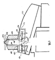
- FIG. 2 the region indicated by the circular area A in FIG. 1 is shown of the turret 28 shown enlarged including slide 36 and Object 38 on its upper side (side facing away from the lens 16 of the from a glass slide formed slide 36).
- an inventive adapter 40 instead of a inserted conventional adapter.
- This adapter 40 is thus without further conversion of the known microscope 10 can be used. He serves the Illumination of the object 38 according to the known principle of TIR (Total Internal Reflection) microscopy.
- the penetration depth of this field depends on the respective reflection angle ⁇ (which still meets the Totalreflexionsbedinung). Accordingly can be by changing the reflection angle ⁇ and the Lighting depth vary.
- an illumination beam which is strongly limited in cross section is used 44 used.
- the limitation is such that he is in the rear Focal plane 46 of the lens 16 substantially forms a point.
- that focal plane is meant that of the illumination beam 44 irradiated lens system of the lens 16 (in Figure 2 by a only front lens 48 indicated) corresponds. It could therefore be behind the Einkoppelstelle (prism 50) of the illumination beam 44 depending on the type of Lens 1 6 quite another lens or lens systems of the lens 16 (toward the eyepiece).
- Theoretically absolute parallelism of the partial beams after passing through the Front lens 48 of the lens is obtained when the illumination beam with the aid of corresponding optical elements (in FIG. 2 through a lens 52 indicated) in the rear (eyepiece) focal plane 46 is focused. It then arise after passing through the front lens 48 inevitably parallel partial beams of the illumination beam 44 with a common Reflection angle ⁇ corresponding to the distance a of the sub-beam 44 of the optical axis 54 of the objective 16.
- the degree of expansion of the illumination beam 44 after passage through the front lens 48 is through the Divergence angle ⁇ of the focused in the rear focal plane 46 illumination beam 44 determined.
- the aforementioned prism 50 is not dargestellen of one Illumination source (in Figure 2 left of the turret 28) coming from Illuminating beam deflected at right angles, so that it is parallel to the optical axis 54 and at a distance to this runs.
- the in the passage 19 located cross-section of the prism 50 is essential smaller than the total cross section of the passage 19. For this reason it is not necessary for the coupling of the illumination beam a Beam splitter, z.
- a dichroic mirror As a dichroic mirror to use, the one Transmission of the observation light coming from the object, because through the prism 50 only a small part of the field of observation of the microscope is obscured.
- the distance a can according to the invention in be particularly simple manner characterized in that the prism 50th either in the direction parallel to the optical axis 54, or as shown in the radial direction (double arrow B) is moved. With the distance a the angle of reflection ⁇ of the illumination beam 44 changes and thus After exceeding the total reflection angle, the penetration depth into the Object. Thus, even after the displacement of the prism 50 of the focus of Illuminating beam 44 is located in the focal plane 46, the need in the beam path provided optical components (symbolized by the lens 52) are adjusted accordingly in their position. If, as in Figure 2 the illumination beam is deflected at right angles, it is special advantageous, the deflection and the focusing serving optical To mount elements on a common support, since then only this carrier must be displaceable in the radial direction.
- the Beam cross section of the illumination beam 44 limited and thus on the Divergence angle ⁇ the degree of expansion of the illumination beam 44 after passing through the front lens 48 determines.
- the adapter 40 can be pulled out of the receptacle 32 again and possibly replaced by a conventional adapter. Further The adapter can also be used in conjunction with any other Lenses of the turret 28 are used, since usually Each lens is associated with a receptacle 32.
- an additional aperture diaphragm 62 in Figure 2 indicated below the prism 50 can be used. These Hides the prism 50 from the observation beam path and prevents possibly disturbing asymmetrical diffraction images (image distortions) the objects introduced by the in the illumination beam path Prism 50.
- the somewhat reduced numerical aperture and resolution can be accepted.
- a further variation of the type of illumination of the object 38 can thereby be achieved that the prism 50 together with the upstream optical components (lens 52) parallel to the optical axis 54 moves. Unless one is out of focus in the back focal plane 46 reaches, there is a certain divergence of the on the interface 42nd incident beam and a change in the degree of expansion.
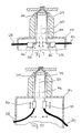
- FIG. 3 shows another embodiment of the adapter designated by 140 40 according to FIG. 2. Accordingly, the other components, if they have their equivalent in components of the adapter 40, with the same reference numerals, each increased by the number 100, provided.
- the adapter 140 In contrast to the adapter 40 with external light source is the adapter 140, the light source 164 integrated into the adapter 140. It closes the Lens 152 and the prism 150 at. After passing through the front lens 148 of the lens 116 and total reflection at the interface 142 is the Illumination beam 144 and the reflection beam 156 by another Prism 166 deflected by 90 ° (diametrically to the prism 150 together with the light source 164) and after passing through a lens 168 in a detector 170 collected.
- the detector 170 can be on the one hand, the optical Align arrangement specifically, especially the total reflection angle in Dependent on the position of the prism 150 and a desired one Range after exceeding the total reflection angle. on the other hand may be local refractive index changes, absorption processes or the like in the area of the interface 142. It is also, a wavelength variation of the light of the light source 164 conceivable.
- the adapter 140 can be selectively rotated about the optical axis 154.
- This offers the Advantage that for objects with anisotropic optical properties the Direction of irradiation of the observation beam 144 can be selectively varied can. You can also choose between rotation during the measurement obtain a uniform illumination of the object.
- FIGS. 4 and 5 show another side view and sectional view, respectively Embodiment of the adapter according to the invention, now with 240th is designated. Its components, which according to their function such 3 correspond to the same reference numerals, each increased by the number 100, provided.
- the reflection beam 256 is led out of the adapter 240 and fed to a detection device, not shown.
- the light source, not shown, is located (in correspondence to FIG. 2) outside of the adapter 240.
- the adjustment possibilities are the same as in the embodiment of Figure 3; which by the appropriate Double arrows D, D ', B, B' and E, E 'is indicated.
- the adapter 240 is between the lens 216 and the turret 228 arranged. He has on his side facing the lens one Port 290 on the lens mount 292 of the turret 228, in which normally the lens 216 is fitted, corresponds. On its turret 228 side facing the adapter 240 has a terminal 286 which is the eyepiece-side terminal 288 of Lens 216, which is normally in the lens mount 292 of the turret 228 is fitted, corresponds. In this way, the Adapter 240 easily integrated into an existing microscope without having to rebuild it.
- the two prisms 250, 266 have rounded reflection surfaces, to minimize the microscopic observation (see Figure 5). Furthermore, in the adapter 240 is on the object 238 facing away from the prisms 250, 266 a filter wheel 272 with axis of rotation 274 arranged in the observation beam path. It can be done with it For example, those portions of the illumination beam 244 that are not considered Reflection beam 256 are coupled out of the adapter 240 again (in particular diffusely scattered portions), from the observation beam path filter out. This is especially true for fluorescence measurements of Advantage.
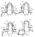
- FIG. 6 of the adapter according to the invention is designated 340. He is different from the one according to the Figures 4 and 5 only in that the prisms 250, 266 are replaced by plane mirrors 350, 366. By displacing the mirror 350 in FIG Direction perpendicular to the optical axis 354 (while maintaining the Spatial orientation), the total reflection angle can be in the same way as change when using a prism
- the two planar mirrors 350, 366 according to FIG. 6 are replaced by curved mirrors, in particular concave mirrors 450, 466.
- the coupling and focusing of the illumination beam 440 may then occur without further optical elements such as an upstream lens accordingly the embodiments described above.
- the beam guidance of the reflection beam 456 takes place symmetrically through the mirror 466.
- FIG. 8 shows in a greatly simplified perspective schematic view a deflection device 576, which is used to couple a plurality of illumination beams 544, 544 ', 544' ', 544' '' and for decoupling the corresponding Reflection rays 556, 556 ', 556' ', 556' '' is used.
- the deflection device 576 consists of concentrically arranged, annularly connected deflecting elements, which in FIG. 8 are trapezoidal Mirrors 550, 550 ', 550' ', 550' '', 566, 566 ', 566' ', 566 ''are shown.
- an illumination beam, z. B. the one provided with the reference numeral 544, on the respective deflecting element, z. B. 550, reflected so that it parallel to after reflection optical axis 554 and passes through the lens 548 on the slide 536 is mapped to the object 538.
- the one at the interface between object stage 536 and object 538 totally reflected illumination beam, z. B.
- each of the illumination beams 544 - 544 '' ' satisfies in the same way the total reflection condition.
- FIGS 9 and 10 are further embodiments of the already in the Figures 2-7 shown adapter shown as a side view.
- the components this adapter designated by the reference numerals 640 and 740, whose function corresponds to that of the adapter shown in FIG. 4, are numbered the same but increased by 400 or 500 provided.
- Adapters 640 and 740 will illuminate the illumination light via a light guide 678 or 778, for example, a glass fiber, in the adapter 640 or 740 introduced.
- the light guide 678 or 778 includes a, z. B. made of microlenses, adapter optics 680 or 780 on to the off the light guide 678 or 778 exiting illumination beam 644 or 744 in the back focal plane 646 and 746, respectively.
- the light guide 678 is perpendicular to the optical axis 654 inserted into the adapter 640 so that he via a deflection unit, which is shown in FIG. 9 as a prism 650, in FIG a direction parallel to the optical axis 654 has to be deflected.
- the optical fiber 778 is as shown in FIG Curved embodiment, so that the adapter optics 780 leaving Focused illumination beam 744 already parallel to the optical Axis 754 is.
- a coupling of the reflection beam 656 and 756 with the help of optical elements, the Coupling used correspond to done.
- this is through the prism 666 and the light guide 682, via the adapter optics 684 with connected to the prism 666 realized.
- this is done by the Optical fiber 782 and mounted at its end adapter optics 784, the with respect to the optical axis 754 symmetrical to that for coupling of the illumination beam 744 used adapter optics 780 is.
- FIGS. 11-14 illustrate embodiments of the present invention the deflection units, which are used to couple the illumination beam or for decoupling the reflection beam serve, in a special Lens 816, 916, 1016, 1116 are intregiert. Components that are theirs Function according to those shown in the preceding figures, are in Figures 11-14 with the same reference numerals, however each increased by the number 100, respectively. Compared to the statements, where the baffle units are integrated in an adapter, offer the In the embodiments illustrated in FIGS. 11-14, the advantage that the for the deflection units require optical components to the lens system of the Lens 816, 916, 1016, 1116 can be adjusted, thereby Overall, the quality of the optical image can be optimized. In addition, such special lenses can also be used for microscopes which do not have an adapter receptacle as in FIG. 2 have shown.
- the illumination beam 844 is transmitted via a bar prism 850 in FIG coupled to the beam path of the microscope.
- the reflection beam 856 via a further bar prism 866 from the lens 816 led out.
- both prisms 850, 866 are in the range of the objective arranged so that they adjust the reflection angle in the Beam path of the microscope in the radial direction are displaced (shown by the double arrows B, B 'in FIG. 11).
- An alternative arrangement of the rod prism 850 is indicated by dashed lines in FIG. In this arrangement is the rod prism 850 'for coupling the illumination beam 844 between the irradiated front lens of the lens and its eyepiece focal plane 846.
- the illumination beam 844 is in In this case, virtually irradiated on the eyepiece focal plane 846 of the Lensensystems focused. This arrangement allows a particularly space saving construction of a special lens with integrated deflection unit.
- optical fibers 1078, 1082, 1178 are used to avoid that of one depict light source coming illumination light in the area of the lens couple into the beam path of the microscope or decouple.
- FIG. 13 which is similar to that in FIG. 9, becomes an attached to the light guide 1078 adapter optics 1080 and a to the adapter optics 1080 adjoining prism 1050 for coupling of the illumination beam 1044.
- the decoupling of the Reflection beam 1056 is made by a with respect to the optical axis 1054 symmetrically arranged prism 1066 and an adjoining Adapter optics 1084, to which a light guide 1082 is coupled.
- Figure 14 an embodiment is shown in Figure 14, in which a curved light guide 1178 with an adapter optics 1180 parallel to optical axis 1154 is connected to the illumination beam 1144 parallel to the optical axis in the beam path of Coupling microscope.
- FIGS. 1 to 14 show different embodiments of a Microscope described which is used in particular for TIR microscopy can be.
- the microscope is in a Auflichtan angel operated, in which the serving for the illumination of the object light through at least part of the objective falls on the object to be observed.
- the illumination beam by an optical device in the Passage between the eyepiece and the lens of the microscope coupled, their lying in the passage cross-section small opposite is the cross section of the passage.
- beam splitter elements eg.
- dichroic mirrors Coupling of the illumination light can be dispensed with.
- It can be one Special lens with integrated optical elements to provide the Illumination beam or for collecting or decoupling the reflection beam be used.
- the mentioned optical Elements can also be integrated into an adapter that is in the beam path an existing microscope can be used.
Abstract
Description
Die Erfindung betrifft ein Mikroskop umfassend
- ein Mikroskopgehäuse,
- ein Objektiv aus mindestens einem jeweils mindestens eine Linse umfassenden Linsensystem an einem Ende eines Durchgangs des Mikroskopgehäuses,
- wenigstens eine Beobachtungseinrichtung, insbesondere ein Okular, an einem anderen Ende des Durchgangs,
- eine Beleuchtungseinrichtung, deren Beleuchtungslicht von einer den Durchgang senkrecht schneidenden Eintrittsebene ausgehend wenigstens einen Beleuchtungsstrahl bildet, der durch das Linsensystem verläuft und in einem vorgegebenen Winkel auf einen Objektträger auftrifft.
- a microscope housing,
- an objective lens comprising at least one lens system comprising at least one lens at one end of a passage of the microscope housing,
- at least one observation device, in particular an eyepiece, at another end of the passage,
- an illumination device whose illuminating light, starting from an entrance plane perpendicularly intersecting the passage, forms at least one illumination beam which runs through the lens system and impinges on a slide at a predetermined angle.
Ein derartiges Mikroskop ist bekannt (Biochemical and Biophysical Research Communications, 235, 47 - 53). Es dient in erster Line der unter dem Begriff TIRM (= Total Internal Reflection Microscopy) bekannten Mikroskopiertechnik. Bei dieser wird der Beleuchtungsstrahl an einer zwischen dem Objektträger und dem Objekt gebildeten Grenzfläche totalreflektiert (Brechungsindex des Objektträgers größer als der Brechungsindex des Objekts), wobei der Beleuchtungsstrahl innerhalb des Objektträgers verläuft, so dass vom Reflexionspunkt ausgehend ein evaneszentes Lichtfeld in das Objekt eindringt mit exponentiellem Intensitätsabfall. Dieses Lichtfeld dient der streng lokal begrenzten Beleuchtung objektträgernaher Bereiche des Objektes. Diese Bereiche können dann in üblicher Weise über Objektiv und Beobachtungseinrichtung, z. B. ein Okular oder eine Kamera, des Mikroskops untersucht werden. Such a microscope is known (Biochemical and Biophysical Research Communications, 235, 47-53). It serves primarily under the Term TIRM (= Total Internal Reflection Microscopy) known microscopy. In this, the illumination beam is at one between the Slides and the object formed interface totally reflected (refractive index the slide is greater than the refractive index of the object), wherein the illumination beam extends within the slide so that Starting from the reflection point an evanescent light field into the object invades with exponential intensity drop. This light field serves the strictly local limited illumination of object areas close to the object. These areas can then in the usual way via lens and Observation device, z. As an eyepiece or a camera, the microscope to be examined.
Bei einer von zwei möglichen TIRM-Anordnungen befindet sich das Objekt auf der dem Mikroskop zugewandten Seite des Objektträgers mit entsprechender Führung des Beleuchtungsstrahls nach Art einer Gegenlichtanordnung (siehe beispielsweise Nature Vol. 374, Seiten 555 - 559 oder Topics in Fluorescence Spetroscopy, Vol. 3, ed. by J. Lakowicz, Plenum Press, New York, 1992, Seite 314 ff.). Die hierzu alternative Auflichtanordnung mit Anordnung des Objekts auf der vom Mikroskop abgelegenen Seite des Objektträgers wird in dem eingangs genannten Stand der Technik angewandt. Das Beleuchtungslicht wird hier von einem Laser außerhalb des Durchgangs des Mikroskops ausgehend über ein Spiegelsystem auf einen dichroitischen Strahlteiler-Spiegel im Durchgang gerichtet und dann parallel zur optischen Achse dem Beobachtungsstrahlengang folgend durch das Objektiv hindurch auf Objektträger und Objekt gerichtet. Der dichroitische Spiegel beeinträchtigt hierbei die mikroskopische Objektbeobachtung, da er den gesamten Querschnitt des Durchgangs durchsetzt und damit die durch das Okular beobachtbare Lichtstrahlung wellenlängenabhängig schwächt.One of two possible TIRM arrangements contains the object on the microscope-facing side of the slide with appropriate Guiding the illumination beam in the manner of a backlight arrangement (See, for example, Nature Vol. 374, pages 555-559 or Topics in Fluorescence Spetoscopy, Vol. 3, ed. by J. Lakowicz, Plenum Press, New York, 1992, page 314 ff.). The alternative Auflichtanordnung with the object arranged on the side of the microscope remote from the object Slides are used in the aforementioned prior art. The illumination light is here by a laser outside the Passing through the microscope on a mirror system on a directed dichroic beam splitter mirror in the passage and then parallel to the optical axis following the observation beam path through the Objectively directed to slide and object. The dichroic Mirror affects the microscopic object observation, since he the entire cross section of the passage interspersed and thus the by the eyepiece attenuates observable light radiation wavelength dependent.
Der Erfindung liegt die Aufgabe zugrunde, ein Mikroskop der eingangs genannten Art mit möglichst geringer Beeinträchtigung der Mikoskopiermöglichkeiten, insbesondere hinsichtlich der möglichen Wellenlängen des Beleuchtungs- bzw. Beobachtungslichts, bereitzustellen.The invention is based on the object, a microscope of the above mentioned type with the least possible impairment of Mikoskopiermöglichkeiten, in particular with regard to the possible wavelengths of the Illumination or observation light to provide.
Diese Aufgabe wird dadurch gelöst, dass der von der Eintrittsebene ausgehende wenigstens eine Beleuchtungsstrahl von einer optischen Einrichtung bereitgestellt wird, deren im Bereich des Durchgangs liegender Querschnitt wesentlich kleiner als der Querschnitt des Durchgangs ist.This object is achieved in that the outgoing from the entrance level at least one illumination beam from an optical device is provided, lying in the region of the passage cross-section is much smaller than the cross section of the passage.
Die Position der Eintrittsebene kann in dem Durchgang zwischen der Frontlinse des Objektivs und der Beobachtungseinrichtung beliebig gewählt werden, wobei auch ein seitliche Einkopplung in die Frontlinse möglich ist. Dadurch, dass das Beleuchtungslicht auf wenigstens einen Beleuchtungsstrahl konzentriert wird, können dementsprechend lokal begrenzte Strahlführungselemente eingesetzt werden, die den Beobachtungsstrahlengang des Mikroskops allenfalls geringfügig beeinträchtigen (in aller Regel außerhalb der optischen Achse). Dieser feine Beleuchtungsstrahl kann ohne weitere Maßnahmen durch das durchstrahlte Linsensystem (ggf. die Front-linse) des Objektivs geschickt werden. Insbesondere kann auf die Verwendung jeglicher Strahlteilereinrichtungen, die den Durchgang durchsetzen, zur Einkopplung des Beleuchtungslichtes verzichtet werden.The position of the entry level may be in the passage between the front lens of the lens and the observation device are arbitrarily selected, whereby a lateral coupling into the front lens is possible. Thereby, that the illumination light is incident on at least one illumination beam Accordingly, locally limited beam guiding elements can be used are used, the observation beam path of the microscope at most slightly impaired (usually outside the optical axis). This fine lighting beam can be done without further Measures by the irradiated lens system (possibly the front lens) of the lens. In particular, on the use any beam splitter devices that pass through the passage, for coupling be dispensed with the illumination light.
Als Lichtquelle für das Beleuchtungslicht kommt beispielsweise ein Laser in Frage, der ein Beleuchtungsstrahlenbündel aus parallelen Einzelstrahlen mit im Wesentlichen punktförmigem Strahlquerschnitt abgibt. Bevorzugt ist jedoch vorgesehen, dass der wenigstens eine Beleuchtungsstrahl in der der Beobachtungseinrichtung zugewandten Brennebene, im Folgenden auch hintere Brennebene genannt, des durchstrahlten Linsensystems des Objektivs in dem Punkt reell oder virtuell fokussiert ist. Hierdurch erreicht man, dass der vom Punkt in der Brennebene als divergierendes Strahlenbündel ausgehende Beleuchtungsstrahl nach Durchgang durch das Linsensystem von einem Strahlenbündel aus parallel verlaufenden Einzelstrahlen gebildet wird, die sämtliche in gleicher Weise die Totalreflexionsbedingung erfüllen.As a light source for the illumination light, for example, a laser comes in Question, the lighting beam of parallel single rays with emits essentially point-shaped beam cross section. Is preferred However, provided that the at least one illumination beam in the Observation device facing focal plane, hereinafter also called the rear focal plane, the lens system of the lens is focused on the point real or virtual. This achieves this one, that of the point in the focal plane as a diverging beam outgoing illumination beam after passing through the lens system from a beam of parallel single rays is formed, all in the same way the total reflection condition fulfill.
Der Beleuchtungsstrahl könnte prinzipiell auch geneigt zur optischen Achse durch das Linsensystem des Objektivs verlaufen. Bevorzugt ist jedoch vorgesehen, dass der wenigstens eine Beleuchtungsstrahl im Wesentlichen parallel zur optischen Achse durch das durchstrahlte Linsensystem des Objektivs verläuft. Der Beleuchtungsstrahl kann hierbei sowohl ausserhalb der optischen Achse als auch entlang der optischen Achse durch das durchstrahlte Linsensystem des Objektivs fallen. Je weiter der Beleuchtungsstrahl in radialer Richtung von der optischen Achse entfernt durch das Linsensystem des Objektivs fällt, desto größer wird der Reflexionswinkel des Beleuchtungsstrahls an der Grenzfläche zwischen Objektträger und Objekt. Um die Totalreflexionsbedingung zu erfüllen, wird man deshalb bevorzugt eine Anordnung wählen, bei der der Beleuchtungsstrahl in der Nähe des Randes der Aperturblende des Objektivs durch das durchstrahlte Linsensystem des Objektivs verläuft. Eine besondere Anwendung erhält man, wenn der Beleuchtungsstrahl im Zentrum des Durchgangs entlang der optischen Achse durch das durchstrahlte Linsensystem des Objektivs verläuft. In diesem Fall trifft der Beleuchtungsstrahl im Wesentlichen rechtwinklig auf die Grenzfläche zwischen Objektträger und Objekt auf, so dass er entlang desselben Weges in das Mikroskop zurückreflektiert wird. Auf diese Weise wird es möglich, ein Mikroskop mit Auflichtanordnung zu realisieren, bei dem das vom Objekt zurückreflektierte Licht beobachtet werden kann, ohne dass Strahlteilereinrichtungen, die das Beobachtungslicht beeinträchtigen, verwendet werden müssen, da durch die den Beleuchtungsstrahl bereitstellende Einrichtung lediglich ein kleiner Bereich im Zentrum des Gesichtsfeldes des Mikroskops abgedeckt wird.The illumination beam could in principle also be inclined to the optical axis pass through the lens system of the lens. However, it is preferred provided that the at least one illumination beam substantially parallel to the optical axis through the irradiated lens system of Lens runs. The illumination beam can here both outside the optical axis as well as along the optical axis through the irradiated lens system of the lens fall. The farther the illumination beam in the radial direction away from the optical axis through the Lens system of the lens falls, the greater the angle of reflection of the illumination beam at the interface between slides and Object. Therefore, to meet the total reflection condition, one becomes preferably choose an arrangement in which the illumination beam in the Near the edge of the aperture of the lens through the irradiated Lens system of the lens runs. A special application receives one, when the illumination beam in the center of the passage along the optical axis through the irradiated lens system of the lens runs. In this case, the illuminating beam is substantially rectangular on the interface between slide and object, so that it is reflected back into the microscope along the same path. On In this way it becomes possible to use a microscope with incident light arrangement realize where the light reflected back from the object is observed can be without beam splitter, the observation light must be used, as by the the illumination beam Providing device only a small area in the Center of the field of view of the microscope is covered.
Besonders bevorzugt ist vorgesehen, dass der wenigstens eine Beleuchtungsstrahl in radialer Richtung in Bezug auf die optische Achse verlagerbar ist. Die seitliche Verlagerung lässt sich durch technisch einfache Mittel erreichen, insbesondere durch in radialer Richtung (in Bezug auf die optische Achse) verlagerbare Umlenkspiegel, Umlenkprismen oder dergleichen. Eine Verlagerung in radialer Richtung führt unmittelbar zu einer entsprechenden Veränderung des Reflexionswinkels an der Grenzschicht zwischen Objektträger und Objekt. Der von Fall zu Fall variierende Totalreflexionswinkel (abhängig von den Brechungsindizes von Objektträger und Objekt) läßt sich in gewünschter Weise einstellen. Weiterhin hängt die Eindringtiefe des Lichtfeldes in das Objekt hinter der Grenzfläche, an der Totalreflexion auftritt, vom Einfallswinkel des Lichtstrahls ab. Somit lässt sich die Tiefe des beleuchteten Objektvolumens durch die radiale Verlagerung des Beleuchtungsstrahls verändern. Weiterhin kann die Tiefe des beleuchteten Volumens auch durch die Wahl von Beleuchtungslicht unterschiedlicher Wellenlänge variiert werden. Da das erfindungsgemäße Mikroskop die Verwendung von Beleuchtungslicht beliebiger Wellenlängen zulässt, ist eine kontinuierliche Veränderung des beleuchteten Objektvolumens auch auf diese Weise möglich. Eine gezielte Veränderung des beleuchteten Objektvolumens und Beobachtung der Intensität des von diesem Volumen ausgehenden Lichtes lässt sich beispielsweise zur Bestimmung der Größe eines sich im Bereich dieses Objektvolumens befindlichen Objektes ausnutzen, da sich die Eindringtiefe des Beleuchtungslichtes aus seiner Wellenlänge und dem eingestellten Totalreflexionswinkel berechnen lässt (siehe hierzu, z. B. Topics in Fluorescence Spectroscopy, Vol. 3, Plenum Press, New York, 1992, Seite 289 ff.).It is particularly preferred that the at least one illumination beam displaceable in the radial direction with respect to the optical axis is. The lateral displacement can be achieved by technically simple means reach, in particular by in the radial direction (with respect to the optical Axis) displaceable deflection mirror, deflection prisms or the like. A displacement in the radial direction leads directly to a corresponding change in the reflection angle at the boundary layer between slide and object. The case-by-case varying total reflection angle (depending on the refractive indices of slides and Object) can be adjusted in the desired manner. Furthermore, the hangs Penetration depth of the light field in the object behind the interface at the Total reflection occurs, from the angle of incidence of the light beam. Thus lets the depth of the illuminated object volume due to the radial displacement of the illumination beam. Furthermore, the depth of the Illuminated volume also by the choice of illumination light different Wavelength can be varied. Since the microscope according to the invention the use of illumination light of any wavelength is a continuous change of the illuminated object volume also possible in this way. A deliberate change of the illuminated Object volume and observation of the intensity of this Volume of outgoing light can be used, for example, to determine the size of an object located in the area of this object volume exploit, since the penetration depth of the illumination light from his Wavelength and the set total reflection angle can be calculated (See, for example, Topics in Fluorescence Spectroscopy, Vol.3, Plenum Press, New York, 1992, page 289 ff.).
Ferner wird vorgeschlagen, dass der Divergenzwinkel des wenigstens einen, von der Eintrittsebene ausgehenden Beleuchtungsstrahls veränderbar ist. Eine Veränderung des Divergenzwinkels hat eine dementsprechende Veränderung des Querschnitts des aus dem Linsensystem austretenden Beleuchtungsstrahls und damit der Größe des beleuchteten Bereichs im Objekt zur Folge.It is also proposed that the divergence angle of at least a changeable from the entrance level illumination beam is. A change in the Divergenzwinkels has a corresponding Change in the cross section of the emerging from the lens system Illuminating beam and thus the size of the illuminated area in the Object result.
Der Divergenzwinkel kann erfindungsgemäß durch Verstellung einer Aperturblende im Strahlengang des Beleuchtungsstrahls variiert werden oder durch Variation der Brennweite der den Beleuchtungsstrahl in der hinteren Brennebene fokussierenden optischen Einheit.The divergence angle can according to the invention by adjusting an aperture diaphragm be varied in the beam path of the illumination beam or by varying the focal length of the illumination beam in the rear Focal plane focusing optical unit.
Wird eine möglichst gleichmäßige Ausleuchtung des Objekts verlangt, so wird bevorzugt ein inkohärenter Beleuchtungsstrahl eingesetzt. Ist dagegen erhöhte Ortsauflösung bzw. strukturierte Beleuchtung gewünscht, so wird bevorzugt ein bzw. mehrere im Wesentlichen kohärente Beleuchtungsstrahlen eingesetzt mit der Möglichkeit der Interferenz im Bereich des Objekts.If a uniform illumination of the object is required, then an incoherent illumination beam is preferably used. Is against increased spatial resolution or structured lighting desired so is preferably one or more substantially coherent illumination beams used with the possibility of interference in the field of Object.
Befindet sich das zu beobachtende Objekt im Bereich der optischen Achse, so wie dies generell der Fall ist, wird der totalreflektierte Anteil des Beleuchtungsstrahls zumindest dann in das Objektiv zurückreflektiert, wenn der Objektträger senkrecht zur optischen Achse angeordnet ist. Normalerweise wird bei der TIR-Mikroskopie von dem beleuchteten Teil des Objekts ausgehendes Fluoreszenzlicht beobachtet, welches Informationen über das Objekt enthält. Um die mikroskopische Beobachtung des Objekts nicht zu beeinträchtigen, wird erfindungsgemäß der zurückreflektierte Anteil des Beleuchtungsstrahls, der Reflexionsstrahl, absorbiert, am besten durch einen. Absorber oder einen Filter unmittelbar hinter dem durchstrahlten Linsensystem. Alternativ oder zusätzlich kann der Reflexionsstrahl auch detektiert werden, sei es zur Justage der Anordnung, insbesondere zur Einstellung des Totalreflexionswinkels und/oder für Absorptionsmessungen am Objekt. Hierfür kann eine Detektionseinrichtung im Bereich des Durchgangs vorgesehen sein. Durch die Beobachtung von Absorptionsvorgängen an der Grenzfläche zwischen Objektträger und Objekt in Abhängigkeit von der Wellenlänge des verwendeten Beleuchtungsstrahls können auch aus dem Reflexionsstrahl zusätzliche Informationen über das Objekt gewonnen werden. Hierfür ist insbesondere wichtig, dass Licht beliebiger Wellenlänge beobachtet werden kann, wie dies erfindungsgemäß der Fall ist.Is the object to be observed in the range of the optical axis, as is generally the case, the total reflected portion of the illumination beam becomes at least then reflected back into the lens, though the slide is arranged perpendicular to the optical axis. Usually becomes in TIR microscopy of the illuminated part of the object outgoing fluorescent light, which contains information about the Contains object. Not to the microscopic observation of the object impair, according to the invention, the reflected portion of the Illumination beam, the reflection beam, absorbed, best through a. Absorber or a filter immediately behind the irradiated Lens system. Alternatively or additionally, the reflection beam can also be detected, it is for adjusting the arrangement, in particular for Adjustment of total reflection angle and / or absorption measurements at the object. For this purpose, a detection device in the region of the passage be provided. By observing absorption processes at the interface between slide and object depending on The wavelength of the illumination beam used may also be off the reflection beam gained additional information about the object become. For this is particularly important that light of any wavelength can be observed, as is the case according to the invention.
Größere Freiheit in der Anordnung und Ausbildung der Detektionseinrichtung erhält man dann, wenn der Reflexionsstrahl mittels einer Umlenkeinheit im Bereich des Durchgangs aus dem Mikroskopstrahlengang herausgeführt wird. Eine entsprechende Umlenkeinheit kann auch zur Einkopplung des Beleuchtungsstrahls in das Mikroskop vorgesehen sein. Auch hier erhält man den Vorteil einer größeren Freiheit in der Anordnung und Ausgestaltung von Lichtquelle und Strahlführung mittels entsprechender optischer Systeme der Beleuchtungseinrichtung. Nichtsdestoweniger kann es in bestimmten Situationen, etwa wenn nicht ausreichend Raum für externe Lichtquellen zur Verfügung steht, von Vorteil sein, eine Lichtquelle mit möglichst punktförmigen Querschnitt, z. B. eine Laserdiode, direkt in den Durchgang im Bereich der Eintrittsebene zu plazieren. Greater freedom in the arrangement and design of the detection device one obtains, then, when the reflection beam by means of a deflection led out of the microscope beam in the region of the passage becomes. A corresponding deflection unit can also be used for coupling be provided of the illumination beam in the microscope. Here too one obtains the advantage of greater freedom in the arrangement and design of light source and beam guidance by means of appropriate optical Systems of the lighting device. Nonetheless, it can be specific Situations, such as when there is not enough room for external Light sources is available, be beneficial to use a light source possibly point-like cross-section, z. As a laser diode, directly into the Passage in the area of the entry level.
In einer ersten Ausführungsform der Erfindung umfasst die Umlenkeinheit ein Prisma. Die Umlenkung erfolgt dann durch Totalreflexion an einer der Prismenflächen. Das Beobachtungsfeld des Mikroskops wird vom Prisma nur wenig beeinträchtigt. Es lässt sich in einfacher Weise haltern und montieren. Eine bewegliche Lagerung zur Justierung des Strahlengangs, insbesondere zur Anpassung des Reflexionswinkels durch Verschiebung in radialer Richtung, lässt sich mit geringem baulichem Aufwand verwirklichen. So kann beispielsweise ein Stabprisma eingesetzt werden mit Umlenkprismenfläche im Durchgang sowie Linearbewegungsführung und Halterung außerhalb des Durchgangs.In a first embodiment of the invention, the deflection unit comprises a prism. The deflection is then carried out by total reflection at one of Prism faces. The field of view of the microscope is from the prism only slightly affected. It can be held in a simple manner and assemble. A movable bearing for adjusting the beam path, in particular for adaptation of the reflection angle by displacement in radial direction, can be realized with little construction effort. For example, a bar prism can be used with deflection prism surface in the passage and linear motion guide and Bracket outside the passage.
Je nach den gewünschten Anforderungen stehen Prismen in unterschiedlichen Formen und Ausbildungen zur Verfügung. In der Grundversion wird ein 90°-Prisma eingesetzt. Das Prisma kann abgerundet sein, um das Beobachtungsfeld möglichst wenig zu beeinträchtigen. An Stelle der 90°-Anordnung können auch andere Winkel gewählt werden. Besondere Vorteile hinsichtlich der Fexibilität der Einbringung des Beleuchtungsstrahls bietet die Kopplung einer Lichtfaser mit einem Umlenkprisma.Depending on the desired requirements prisms are available in different Forms and training available. In the basic version will a 90 ° prism used. The prism can be rounded to the Observation field as little as possible. Instead of the 90 ° arrangement Other angles can also be selected. Special advantages in terms of the flexibility of the introduction of the illumination beam offers the coupling of an optical fiber with a deflection prism.
In Fällen, in denen eine Dispersion des Beleuchtungsstrahls vermieden werden soll oder die Wellenlänge des Beleuchtungsstrahls variiert wird, kann an Stelle des Prismas auch ein Umlenkspiegel eingesetzt werden. Im Allgemeinen wird man einen ebenen Umlenkspiegel einsetzen. Es ist jedoch auch der Einsatz eines gekrümmten Spiegels denkbar, der der Fokussierung des Strahls in der hinteren Brennebene dienen kann, so dass entsprechende Linsenelemente wegfallen können.In cases where dispersion of the illumination beam is avoided or the wavelength of the illumination beam is varied, can be used instead of the prism and a deflection mirror. in the Generally you will use a level deflecting mirror. However, it is also the use of a curved mirror conceivable, that of focusing of the jet can serve in the rear focal plane, so that appropriate Lens elements can be omitted.
Bei der erfindungsgemäßen Anordnung wird wenigstens ein Beleuchtungsstrahl eingesetzt, wobei jeweiligen Anforderungen entsprechend auch mehrere Beleuchtungsstrahlen Verwendung finden können. In einem solchen Fall wird mit Vorteil eine Umlenkeinrichtung eingesetzt, in der eine entsprechende Vielzahl von Umlenkeinheiten baulich integriert ist. In diesem Falle ist die Umlenkeinrichtung bevorzugt angenähert ringförmig ausgebildet und konzentrisch zur optischen Achse angeordnet. An diesem Ring sind dann die entsprechend geneigten Reflexionsflächen (Spiegelflächen bzw. Prismenflächen) ausgebildet. Weiterhin ist es möglich, den Beleuchtungsstrahl durch einen gekrümmten Lichtleiter in den Strahlengang des Mikroskops einzuführen. In diesem Falle wird die Umlenkeinheit vom gekrümmten Lichtleiter selbst gebildet.In the arrangement according to the invention at least one illumination beam used, whereby according to respective requirements also multiple illumination beams can be used. In such a Case, a deflection device is advantageously used, in which a corresponding plurality of deflection is structurally integrated. In this Trap, the deflection is preferably formed approximately annular and concentric with the optical axis. At this ring are then the corresponding inclined reflection surfaces (mirror surfaces or prism surfaces). Furthermore, it is possible to use the illumination beam through a curved light guide into the beam path of the Introduce microscope. In this case, the deflection of the curved Light guide itself formed.
Die erfindungsgemäße Anordnung aus einzelnen Beleuchtungsstrahlen, insbesondere aus einem einzigen Beleuchtungsstrahl, ermöglicht die Beleuchtung des Objekts mit einem aus einer einzigen Richtung kommenden Beleuchtungsstrahl. Bei räumlich komplexen Gebilden, wie z. B. Zellen, können sich je nach Einstrahlrichtung des Beleuchtungsstrahls unterschiedliche Bilder des Objekts ergeben. Man erhält hierdurch zusätzlich Informationen über das Objekt. Es kann in solch einem Falle daher von Vorteil sein, wenn, wie erfindungsgemäß vorgeschlagen, die wenigstens eine Umlenkeinheit oder, falls eine Lichtquelle im Durchgang angeordnet ist, die Lichtquelle um die optische Achse rotierbar ist. Um den Reflexionsstrahl zu detektieren oder zu absorbieren, ist es zweckmäßig, ggf. auch die Detektions- bzw. Absorptionseinrichtung um die optische Achse zu drehen.The arrangement according to the invention of individual illumination beams, in particular from a single beam of illumination, allows the lighting of the object with one coming from a single direction Illumination beam. For spatially complex structures, such. Cells, can vary depending on the direction of the illumination beam Images of the object result. This gives additional information about the object. It may therefore be advantageous in such a case, if, as proposed by the invention, the at least one deflection unit or, if a light source is located in the passage, the light source is rotatable about the optical axis. To the reflection beam too detect or absorb, it is appropriate, if necessary, also the detection or absorption device to rotate about the optical axis.
Die Rotation der Umlenkeinheit und damit die Rotation des auf die Probe einfallenden Beleuchtungsstrahls kann, wie ausgeführt, zwischen den Messungen vorgenommen werden, aber auch während einer Messung, um eine gleichmäßige Ausleuchtung des Objekts zu erhalten.The rotation of the deflection unit and thus the rotation of the on the sample incident illumination beam, as stated, between the Measurements are made, but also during a measurement to to obtain a uniform illumination of the object.
Da erfindungsgemäß über die wenigstens eine Umlenkeinheit das Beleuchtungslicht erst im Bereich des Objektivs in das Mikroskop eingekoppelt und ggf. dort auch wieder ausgekoppelt wird, kann der Beleuchtung des Objekts dienendes Licht, welches nicht Teil des Reflexionsstrahls ist und dennoch in das Mikroskop zurückreflektiert bzw. zurückgestreut ist, in einfacher Weise aus dem Beobachtungsstrahlengang entfernt werden, nämlich durch eine Filteranordnung auf der objektfernen Seite der wenigstens einen Umlenkeinheit.Since according to the invention on the at least one deflecting the illumination light only in the area of the lens coupled into the microscope and if necessary, it is also decoupled there, the illumination of the object serving light, which is not part of the reflection beam and nevertheless reflected back into the microscope, in be easily removed from the observation beam path, namely by a filter arrangement on the far side of the object at least a deflection unit.
Die erfindungsgemäße Beschränkung der Strahlführung des Beleuchtungsstrahls sowie des Reflexionsstrahls auf den Objektivbereich ermöglicht den Einsatz eines Adapters, der zwischen dem Objektiv und der Beobachtungseinrichtung angeordnet ist und der wenigstens die eine Umlenkeinheit oder ggf. die eine Lichtquelle aufweist. Mit Hilfe des Adapters lässt sich die Lichtquelle der Beleuchtungseinrichtung ohne Weiteres einkoppeln, wobei die Lichtquelle (im Falle dass sie sich nicht im Durchgang befindet) unabhängig von dem Adapter sein kann oder auch in den Adapter integriert sein kann. Wahlweise lässt sich der Adapter wieder entfernen oder gegen andere Adaptereinrichtungen austauschen, was einen vielfältigen Einsatz des Mikroskops zulässt. Bestehende Mikroskope können unter Umständen umgebaut bzw. nachgerüstet werden, indem bereits herkömmlicherweise vorgesehene Adaptereinsätze, insbesondere sog. DIC (Differentieller Interferenzkontrast)-Slider, die optische Komponenten aufweisen, welche zur DIC-Mikroskopie verwendet werden, gegen den erfindungsgemäßen Adapter ausgetauscht werden. Eine weitere einfache Möglichkeit, bestehende Mikroskope nachzurüsten, bietet ein Adapter, der zwischen dem Objektiv und dem Objektivanschluss des Mikroskopgehäuses angeordnet ist. Idealerweise weist ein solcher Adapter auf seiner dem Objektiv zugewandten Seite einen gleichartigen Anschluss auf wie der Objektivanschluss des Mikroskopgehäuses, in den normalerweise das Objektiv eingepasst wird. Weiterhin ist es vorteilhaft, wenn der Adapter auf seiner dem Mikroskopgehäuse zugewandten Seite einen gleichartigen Anschluss wie der dem Mikroskopgehäuse zugewandte Anschluss des Objektivs aufweist. In diesem Fall kann der Adapter, ohne dass ein bestehendes Mikroskop umgebaut werden müsste, einfach zwischen Objektiv und Mikroskopgehäuse in den Durchgang eingesetzt werden, da sich in der Regel bei einem Mikroskop die Länge des Durchgangs zwischen der Beobachtungseinrichtung und dem objektivseitigen Anschluss des Mikroskopgehäuses verändern lässt. The inventive restriction of the beam guidance of the illumination beam and the reflection beam on the lens area allows the Use of an adapter between the lens and the observation device is arranged and the at least one deflection unit or possibly having a light source. With the help of the adapter can be the Incorporate light source of the lighting device readily, wherein the light source (in case it is not in the passage) independent may be from the adapter or integrated into the adapter can be. Optionally, the adapter can be removed again or against replace other adapter devices, which is a versatile use of the microscope. Existing microscopes may work be rebuilt or retrofitted by already conventionally provided adapter inserts, in particular so-called DIC (Differential Interference Contrast) slider, have the optical components, which for DIC microscopy can be used against the adapter according to the invention be replaced. Another easy way to existing ones Retrofit microscopes, provides an adapter, which is between the lens and the lens connection of the microscope housing is arranged. Ideally has such an adapter on its lens facing Page a similar connection on how the lens mount of Microscope housing in which normally the lens is fitted. Furthermore, it is advantageous if the adapter on his the microscope housing facing side a similar connection as the Having microscope housing facing connection of the lens. In In this case, the adapter can be rebuilt without having an existing microscope would have to, just between lens and microscope housing in The passage can be used, as is usually the case with a microscope the length of the passage between the observer and can change the lens-side connection of the microscope housing.
Es ist sogar möglich, die Umlenkeinheit in einem entsprechend angepassten Objektiv zu integrieren. Die optischen Bauelemente können so optimal aufeinander abgestimmt werden. Auch bedarf es keines sonstigen Umbaus des Mikroskops, da lediglich ein herkömmliches Objektiv gegen ein erfindungsgemäßes auszutauschen ist.It is even possible, the deflection unit in a suitably adapted To integrate lens. The optical components can be optimally be coordinated with each other. Also, there is no need for any other reconstruction of the microscope, since only a conventional lens against an inventive is to exchange.
In der Adapterbox bzw. dem erfindungsgemäßen Objektiv kann zusätzlich zur Umlenkeinheit die Lichtquelle integriert werden bzw. die Detektoreinrichtung für den Reflexionsstrahl.In the adapter box or the lens according to the invention can additionally the light source is integrated with the deflection unit or the detector device for the reflection beam.
Die Erfindung wird im Folgenden an mehreren Ausführungsbeispielen anhand der Zeichnung erläutert. Es zeigt:
- Figur 1
- eine grob schematische Schnittdarstellung eines Mikroskops mit Auflichtanordnung und strichliert angedeutetem Adapter;
- Figur 2
- eine Detailansicht (Pfeil A) der Anordnung in Figur 1 mit einer erfindungsgemäß ausgebildeten Ausführung eines Adapters und externer nicht dargestellter Lichtquelle;
Figur 3- eine Ansicht entsprechend Figur 2 eines abgewandelten Adapters mit interner Lichtquelle;
- Figur 4
- eine Schnittansicht ähnlich der Figuren 2 und 3 einer weiteren Ausführungsform des Adapters samt Objektiv unter Weglassung der übrigen Mikroskopbauteile mit Prisma als Umlenkeinheit;
- Figur 5
- einen Schnitt der Anordnung gemäß Figur 4 nach Linie V-V in Figur 4;
- Figur 6
- einen Schnitt ähnlich Figur 4 einer weiteren Ausführungsform des Adapters unter Weglassung eines objektfernen Teils des Adapters mit ebenem Spiegel als Umlenkeinheit;
- Figur 7
- eine Ansicht ähnlich Figur 6 einer weiteren Ausführungsform des Adapters mit gekrümmten Spiegel als Umlenkeinheit;
- Figur 8
- eine stark vereinfachte perspektivische Schemaansicht einer Umlenkeinrichtung aus konzentrisch angeordneten ringartig zusammenhängenden Umlenkelementen samt durch eine einzige Linse symbolisiertem Linsensystem und Objektträger mit Objekt und eingezeichnetem Strahlengang;
- Figur 9
- eine Ansicht ähnlich Figur 6 mit prismatischem Umlenkelement und angekoppeltem Lichtleiter;
Figur 10- eine Ansicht ähnlich Figur 9 mit von einem gekrümmtem Abschnitt des Lichtleiters gebildetem Umlenkelement;
- Figur 11
- eine Schnittansicht mit im Objektiv integrierter Umlenkeinheit in Form eines Prismenstabs;
Figur 12- eine Anordnung ähnlich Figur 11 mit im Objektiv integrierter Umlenkeinheit in Form eines Doppelprismas;
- Figur 13
- eine Ansicht ähnlich Figur 11 mit an den Prismenstab angekoppeltem Lichtleiter und
Figur 14- eine Anordnung ähnlich Figur 13 mit gekrümmtem Lichtleiterabschnitt als Umlenkeinheit.
- FIG. 1
- a rough schematic sectional view of a microscope with Auflichtanordnung and dashed lines indicated adapter;
- FIG. 2
- a detailed view (arrow A) of the arrangement in Figure 1 with an inventive design of an adapter and external light source not shown;
- FIG. 3
- a view corresponding to Figure 2 of a modified adapter with internal light source;
- FIG. 4
- a sectional view similar to Figures 2 and 3 of another embodiment of the adapter, including the lens, omitting the other microscope components with prism as a deflection unit;
- FIG. 5
- a section of the arrangement according to Figure 4 along the line VV in Figure 4;
- FIG. 6
- a section similar to Figure 4 of another embodiment of the adapter, omitting an object-distant part of the adapter with a plane mirror as a deflection unit;
- FIG. 7
- a view similar to Figure 6 of another embodiment of the adapter with a curved mirror as a deflection unit;
- FIG. 8
- a highly simplified perspective schematic view of a deflection of concentrically arranged ring-like contiguous deflection together with symbolized by a single lens lens system and slide with object and marked beam path;
- FIG. 9
- a view similar to Figure 6 with prismatic deflector and coupled optical fiber;
- FIG. 10
- a view similar to Figure 9 with formed by a curved portion of the light guide deflecting element;
- FIG. 11
- a sectional view with integrated in the lens deflecting unit in the form of a prismatic rod;
- FIG. 12
- an arrangement similar to Figure 11 with the lens integrated deflection unit in the form of a double prism;
- FIG. 13
- a view similar to Figure 11 with coupled to the prismatic light guide and
- FIG. 14
- an arrangement similar to Figure 13 with curved light guide section as a deflection unit.
Die schematische Schnittzeichnung gemäß Figur 1 zeigt ein herkömmliches
Mikroskop in invertierter Anordnung (Carl Zeiss Axiovert 100, 135, 135M,
Carl Zeiss Jena). Von dem allgemein mit 10 bezeichneten Mikroskop sind
die Hauptbestandteile erkennbar, nämlich ein visuelles Beobachtungsteil 12
mit Okular 14 an einem Ende des Strahlengangs und Objektiv 16 am anderen
Ende und einer Vielzahl dazwischen geschalteter optischer Komponenten
innerhalb eines Durchgangs 19 eines Mikroskopgehäuses 18.
In den Strahlengang einkoppelbar ist der Strahlengang eines photographischen
Beobachtungsteils mit im Umriss angedeuteter Kamera 22.The schematic cross-sectional view of Figure 1 shows a conventional microscope in an inverted arrangement (Carl Zeiss Axiovert 100, 135, 135M, Carl Zeiss Jena). Of the generally designated 10 microscope, the main components are recognizable, namely a
The beam path of a photographic observation part with
In den visuellen Strahlengang ist ferner der Strahlengang eines Beleuchtungsteils
24 einkoppelbar (über einen teildurchlässigen Spiegel 26 unterhalb
eines das Objektiv 16 tragenden Objektivrevolverkopfes 28 mit Revolverdrehachse
30).In the visual beam path is also the beam path of a
Bei dem herkömmlichen Mikroskop 10 ist eine in Figur 1 strichliert angedeutete
Adapteraufnahme 32 vorgesehen, die der Aufnahme von Adaptern
(DIC-Slider), insbesondere eines Wollaston-Prismas zur Beobachtung von
Objekten im differentiellen Interferenzkontrast, dient.In the
An das Objektiv 16 schließt sich in Figur 1 nach oben hin ein in Figur 1
weggelassener Objektträger für das zu mikroskopierende Objekt an. Dieses
wird in der dargestellten Anordnung durch das Beleuchtungsteil von Seiten
des Beobachters her beleuchtet (Auflichtanordnung). Wird eine Durchleuchtung
des Objekts gewünscht, so kann ein in Figur 1 nicht dargestelltes
Beleuchtungsteil für eine entsprechende Beleuchtung der Probe (in Figur
1 von oben her) an einem in Figur 1 abgebrochen dargestellten nach oben
vom Mikroskop 10 abstehenden Träger 34 angeordnet sein.The
In Figur 2 ist der in Figur 1 durch die Kreisfläche A angedeutete Bereich
des Revolverkopfs 28 vergrößert dargestellt samt Objektträger 36 und
Objekt 38 auf dessen Oberseite (vom Objektiv 16 abgewandte Seite des
von einem Glasplättchen gebildeten Objektträgers 36).In FIG. 2, the region indicated by the circular area A in FIG. 1 is shown
of the
In die Aufnahme 32 ist ein erfindungsgemäßer Adapter 40 an Stelle eines
herkömmlichen Adapters eingeschoben. Dieser Adapter 40 ist also ohne
weiteren Umbau des bekannten Mikroskops 10 einsetzbar. Er dient der
Beleuchtung des Objekts 38 gemäß dem an sich bekannten Prinzip der TIR
(Total Internal Reflection) -Mikroskopie.In the
Bei dieser Mikroskopiertechnik wird an einer zwischen Objektträger 36 und
Objekt 38 gebildeten Grenzfläche 42 von der Objektträgerseite her kommendes
Licht totalreflektiert (Brechungsindex des Objekts kleiner als der
Brechungsindex des Objektträgers). Vom Totalreflexionpunkt aus erstreckt
sich ein sogenanntes evaneszentes Beleuchtungsfeld in das Objekt hinein,
welches exponentionell mit dem Abstand von der Grenzfläche abfällt. Man
erhält so eine in axialer Richtung lokal sehr scharf begrenzte Art der Beleuchtung.
Um den Totalrefelxionswinkel zu erhalten wird ein Objektiv mit
genügend hoher numerischer Apertur NA eingesetzt. Beispielsweise muss
bei einer Glas-Wasser-Grenzfläche ein Objektiv mit hoher numerischer
Apertur (NA > 1,33) eingesetzt werden, um den Totalreflexionswinkel zu
erhalten.In this microscopy technique is at a between
Die Eindringtiefe dieses Feldes hängt hierbei vom jeweiligen Reflexionswinkel β ab (der der Totalreflexionsbedinung weiterhin genügt). Dementsprechend lässt sich durch Veränderung des Reflexionswinkels β auch die Beleuchtungstiefe variieren.The penetration depth of this field depends on the respective reflection angle β (which still meets the Totalreflexionsbedinung). Accordingly can be by changing the reflection angle β and the Lighting depth vary.
Erfindungsgemäß wird ein im Querschnitt stark begrenzter Beleuchtungsstrahl
44 verwendet. Die Begrenzung ist derart, dass er in der hinteren
Brennebene 46 des Objektivs 16 im Wesentlichen einen Punkt bildet.
Hierbei ist diejenige Brennebene gemeint, die dem vom Beleuchtungsstrahl
44 durchstrahlten Linsensystem des Objektivs 16 (in Figur 2 durch eine
einzige Frontlinse 48 angedeutet) entspricht. Es könnten daher hinter der
Einkoppelstelle (Prisma 50) des Beleuchtungsstrahls 44 je nach Bauart des
Objektivs 1 6 durchaus noch weitere Linsen oder Linsensysteme des Objektivs
16 angeordnet sein (in Richtung zum Okular).According to the invention, an illumination beam which is strongly limited in cross section is used
44 used. The limitation is such that he is in the
Bei Verwendung eines feinen Laserstrahls als Beleuchtungsstrahl 44 könnte dieser ohne Einsatz von Fokussierungslinsen durch das frontseitige Linsensystem (symbolisiert durch die Frontlinse 48) geschickt werden, wenn auch eine schwache Divergenz des aus der Frontlinse austretenden Strahls unvermeidlich ist, da die vor der Frontlinse noch parallelen Teilstrahlen anschließend auf den Brennpunkt F strahlenförmig zulaufen. Dementsprechend unterscheiden sich die Reflexionswinkel dieser Teilstrahlen voneinander geringfügig. Dies mag in manchen Fällen in Kauf genommen werden können.Using a fine laser beam as the illumination beam 44 could this without the use of focusing lenses through the front lens system (symbolized by the front lens 48) will be sent, though a slight divergence of the beam emerging from the front lens is inevitable, since the front of the front lens still parallel partial beams then run towards the focal point F in a radiating manner. Accordingly The reflection angles of these partial beams differ from each other slightly. This may be acceptable in some cases can.
Theoretisch absolute Parallelität der Teilstrahlen nach Durchgang durch die
Frontlinse 48 des Objektivs erhält man dann, wenn der Beleuchtungsstrahl
mit Hilfe entsprechender optischer Elemente (in Figur 2 durch eine Linse 52
angedeutet) in die hintere (okularseitige) Brennebene 46 fokussiert wird. Es
ergeben sich dann nach Durchgang durch die Frontlinse 48 zwangsläufig
parallele Teilstrahlen des Beleuchtungsstrahls 44 mit einem gemeinsamen
Reflexionswinkel β entsprechend dem Abstand a des Teilstrahls 44 von der
optischen Achse 54 des Objektivs 16. Der Grad der Aufweitung des Beleuchtungsstrahls
44 nach Durchgang durch die Frontlinse 48 ist durch den
Divergenzwinkel α des in der hintere Brennebene 46 fokussierten Beleuchtungsstrahls
44 festgelegt.Theoretically absolute parallelism of the partial beams after passing through the
Front lens 48 of the lens is obtained when the illumination beam
with the aid of corresponding optical elements (in FIG. 2 through a
Mit Hilfe des bereits erwähnten Prismas 50 wird der von einer nicht dargestellen
Beleuchtungsquelle (in Figur 2 links vom Revolverkopf 28) herkommende
Beleuchtungsstrahl rechtwinklig umgelenkt, so dass er parallel zur
optischen Achse 54 und mit Abstand a zu dieser verläuft. Hierbei ist der in
dem Durchgang 19 befindliche Querschnitt des Prismas 50 wesentlich
kleiner als der Gesamtquerschnitt des Durchgangs 19. Aus diesem Grunde
ist es nicht erforderlich, zur Einkopplung des Beleuchtungsstrahls einen
Strahlteiler, z. B. einen dichroitischen Spiegel, zu verwenden, der eine
Transmission des vom Objekt herkommenden Beobachtungslichtes zulässt,
da durch das Prisma 50 lediglich ein kleiner Teil des Beobachtungsfeldes
des Mikroskops verdeckt wird. Der Abstand a kann erfindungsgemäß in
besonders einfacher Weise dadurch variiert werden, dass das Prisma 50
entweder in Richtung parallel zur optischen Achse 54, oder wie dargestellt
in radialer Richtung (Doppelpfeil B) verschoben wird. Mit dem Abstand a
ändert sich der Reflexionswinkel β des Beleuchtungsstrahls 44 und damit
nach Überschreiten des Totalreflexionswinkels die Eindringtiefe in das
Objekt. Damit auch nach der Verschiebung des Prismas 50 der Fokus des
Beleuchtungsstrahls 44 in der Brennebene 46 liegt, müssen die im Strahlengang
vorgesehenen optischen Bauelemente (symbolisiert durch die Linse
52) dementsprechend in ihrer Lage angepasst werden. Falls wie in Figur 2
der Beleuchtungsstrahl rechtwinklig umgelenkt wird, ist es besonders
vorteilhaft, die Umlenkeinheit und die der Fokussierung dienenden optischen
Elemente auf einem gemeinsamen Träger zu montieren, da dann nur
dieser Träger in radialer Richtung verlagerbar sein muss.With the help of the
In der in Figur 2 dargestellten Anordnung mit zur optischen Achse 54
senkrechter Grenzfläche 42 zwischen Objektträger 36 und Objekt 38 tritt
der Beleuchtungsstrahl nach Reflexion an der Grenzfläche 42 (nunmehr
Reflexionsstrahl 56 genannt) wieder durch die Frontlinse 48 in das Objektiv
16 ein (symmetrisch zum Beleuchtungsstrahl 44). Damit der Reflexionsstrahl
56 nicht die mikroskopische Beobachtung des Objekts 38 stört, wird
dieser in der Ausführungsform gemäß Figur 2 durch einen Absorber 58
absorbiert, der hier an einer dem Ort des Prismas 50 entsprechenden Stelle
auf der anderen Seite der optischen Achse 54 angeordnet ist. Um möglichst
wenig die mikroskopische Beobachtung zu stören, kann der Absorber
58 jeweils möglichst weit radial nach außen gezogen werden, was durch
den Doppelpfeil B' angedeutet ist. In the arrangement shown in Figure 2 with the optical axis 54th
Zu erwähnen ist noch die Aperturblende 60 vor der Linse 52, die den
Strahlquerschnitt des Beleuchtungsstrahls 44 begrenzt und damit über den
Divergenzwinkel α den Grad der Aufweitung des Beleuchtungsstrahls 44
nach Durchgang durch die Frontlinse 48 festlegt. Eine weitere Möglichkeit,
den Divergenzwinkel α zu verändern, besteht darin, die Brennweite der
Linse 52 zu variieren, wobei dann die Position der Linse 52 (siehe Doppelpfeil
D) und ggf. die gemeinsame Position von Linse 52 und Prisma 50 in
axialer Richtung (siehe den Doppelpfeil E) so nachgeführt werden müssen,
dass der Beleuchtungsstrahl weiterhin in der hinteren Brennebene 46
fokussiert ist.To mention is still the aperture 60 in front of the
Im Bedarfsfall kann der Adapter 40 wieder aus der Aufnahme 32 herausgezogen
und ggf. durch einen herkömmlichen Adapter ersetzt werden. Ferner
kann der Adapter auch ohne Weiteres in Verbindung mit beliebigen anderen
Objektiven des Revolverkopfes 28 eingesetzt werden, da üblicherweise
jedem Objektiv eine Aufnahme 32 zugeordnet ist.If necessary, the
Zum optischen Aufbau sei noch ergänzt, dass in den Durchgang 19 zwischen
der Einkoppelstelle des Beleuchtungsstrahls (Prisma 50) und der
Beobachtungseinrichtung eine zusätzliche Aperturblende 62 (in Figur 2
unterhalb des Prismas 50 angedeutet) eingesetzt werden kann. Diese
blendet das Prisma 50 aus dem Beobachtungsstrahlengang aus und verhindert
dadurch eventuell störende asymmetrische Beugungsbilder (Bildverzerrungen)
der Objekte durch das in den Beleuchtungsstrahlengang eingebrachte
Prisma 50. Die etwas reduzierte numerische Apertur und Auflösung
kann in Kauf genommen werden.To the optical structure is still added that in the
Eine weitere Variation der Art der Beleuchtung des Objekts 38 kann dadurch
erzielt werden, dass man das Prisma 50 samt den vorgeschalteten
optischen Bauelementen (Linse 52) parallel zur optischen Achse 54 verlagert.
Sofern man dabei aus dem Fokus in der hinteren Brennebene 46
gelangt, ergibt sich eine gewisse Divergenz des auf die Grenzfläche 42
auftreffenden Strahls sowie eine Änderung des Grads der Aufweitung.A further variation of the type of illumination of the
Figur 3 zeigt eine weitere mit 140 bezeichnete Ausführungsform des Adapters
40 gemäß Figur 2. Dementsprechend sind auch die übrigen Bauteile,
sofern sie ihre Entsprechung in Bauteilen des Adapters 40 haben, mit
denselben Bezugsziffern, jeweils vermehrt um die Zahl 100, versehen.FIG. 3 shows another embodiment of the adapter designated by 140
40 according to FIG. 2. Accordingly, the other components,
if they have their equivalent in components of the
Im Gegensatz zum Adapter 40 mit externer Lichtquelle ist beim Adapter
140 die Lichtquelle 164 in den Adapter 140 integriert. Es schließt sich die
Linse 152 sowie das Prisma 150 an. Nach Durchgang durch die Frontlinse
148 des Objektivs 116 und Totalreflexion an der Grenzfläche 142 wird der
Beleuchtungsstrahl 144 bzw. der Reflexionsstrahl 156 durch ein weiteres
Prisma 166 um 90° abgelenkt (diametral zum Prisma 150 samt Lichtquelle
164) und nach Durchgang durch eine Linse 168 in einem Detektor 170
aufgefangen. Durch den Detektor 170 läßt sich zum einen die optische
Anordnung gezielt justieren, insbesondere der Totalreflexionswinkel in
Abhängigkeit von der Position des Prismas 150 sowie ein gewünschter
Bereich nach Überschreitung des Totalreflexionswinkels. Andererseits
lassen sich unter Umständen lokale Brechungsindex-Änderungen, Absorptionsvorgänge
oder dgl. im Bereich der Grenzfläche 142 erfassen. Dabei ist
auch eine Wellenlängenvariation des Lichts der Lichtquelle 164 denkbar.In contrast to the
Mit den Doppelpfeilen B und B' ist wiederum die radiale Justierbarkeit der
Prismen 150, 166 andedeutet, mit den Doppelpfeilen E und E' die Beweglichkeit
der Prismen 150 bzw. 166 samt Lichtquelle 164 und Linse 152
bzw. Detektor 170 und vorgeschalteter Linse 168 parallel zur optischen
Achse 154, mit D, D' die Justierbeweglichkeit der Linsen 152, 168.With the double arrows B and B 'turn the radial adjustability of
Prinzipell ist es auch denkbar, den Adapter 140 derart auszubilden, dass er
um die optische Achse 154 wahlweise rotiert werden kann. Dies bietet den
Vorteil, dass bei Objekten mit anisotropen optischen Eigenschaften die
Einstrahlrichtung des Beobachtungsstrahls 144 wahlweise variiert werden
kann. Auch kann man wahlweise durch Rotation während der Messung
eine gleichmäßige Ausleuchtung des Objekts erhalten.In principle, it is also conceivable to form the
Figuren 4 und 5 zeigen in Seitenansicht bzw. Schnittansicht eine weitere Ausführungsform des erfindungsgemäßen Adapters, der nunmehr mit 240 bezeichnet ist. Seine Bauelemente, die ihrer Funktion nach solchen der Figur 3 entsprechen, sind mit denselben Bezugsziffern, jeweils vermehrt um die Zahl 100, versehen.FIGS. 4 and 5 show another side view and sectional view, respectively Embodiment of the adapter according to the invention, now with 240th is designated. Its components, which according to their function such 3 correspond to the same reference numerals, each increased by the number 100, provided.
Auch hier sind für die Einkopplung des Beleuchtungsstrahls 244 bzw. zur
Auskopplung des Reflexionsstrahls 256 Prismen 250, 266 vorgesehen mit
vorgeschalteten Linsen 252, 268. Im Unterschied zur Ausführungsform
gemäß Figur 3 wird der Reflexionsstrahl 256 aus dem Adapter 240 herausgeführt
und einer nicht dargestellten Detektionseinrichtung zugeführt.
Auch die nicht dargestellte Lichtquelle befindet sich (in Entsprechung zu
Figur 2) außerhalb des Adapters 240. Die Justiermöglichkeiten sind die
gleichen wie bei der Ausführungsform gemäß Figur 3; was durch die entsprechenden
Doppelpfeile D, D', B, B' und E, E' angedeutet ist.Again, for the coupling of the
Der Adapter 240 ist zwischen dem Objektiv 216 und dem Revolverkopf
228 angeordnet. Er weist an seiner dem Objektiv zugewandten Seite einen
Anschluss 290 auf, der dem Objektivanschluss 292 des Revolverkopfes
228, in den normalerweise das Objektiv 216 eingepasst wird, entspricht.
Auf seiner dem Revolverkopf 228 zugewandten Seite weist der Adapter
240 einen Anschluss 286 auf, der dem okularseitigen Anschluss 288 des
Objektivs 216, der normalerweise in den Objektivanschluss 292 des Revolverkopfes
228 eingepasst wird, entspricht. Auf diese Weise kann der
Adapter 240 in einfacher Weise in ein bestehendes Mikroskop integriert
werden, ohne dass dieses umgebaut werden muss. The
Die beiden Prismen 250, 266 weisen abgerundete Reflexionsflächen auf,
um die mikroskopische Beobachtung möglichst wenig zu beeinträchtigen
(siehe Figur 5). Desweiteren ist in dem Adapter 240 auf der vom Objekt
238 abgewandten Seite der Prismen 250, 266 ein Filterrad 272 mit Drehachse
274 im Beobachtungsstrahlengang angeordnet. Es lassen sich damit
beispielsweise diejenigen Anteile des Beleuchtungsstrahls 244, die nicht als
Reflexionsstrahl 256 wieder aus dem Adapter 240 ausgekoppelt werden
(insbesondere diffus gestreute Anteile), aus dem Beobachtungsstrahlengang
herausfiltern. Dies ist insbesondere bei Fluoreszenzmessungen von
Vorteil.The two
Die in Figur 6 dargestellte Ausführungsform des erfindungsgemäßen Adapters
ist mit 340 bezeichnet. Er unterscheidet sich von dem gemäß den
Figuren 4 und 5 lediglich darin, dass die Prismen 250, 266 ersetzt sind
durch ebene Spiegel 350, 366. Durch Verlagerung des Spiegels 350 in
Richtung senkrecht zur optischen Achse 354 (unter Beibehaltung der
Raumorientierung) läßt sich der Totalreflexionswinkel in gleicher Weise wie
beim Einsatz eines Prismas verändernThe embodiment shown in Figure 6 of the adapter according to the invention
is designated 340. He is different from the one according to the
Figures 4 and 5 only in that the
Bei der mit 440 bezeichneten Ausführungsform des Adapters gemäß Figur
7 sind die beiden ebenen Spiegel 350, 366 gemäß Figur 6 ersetzt durch
gekrümmte Spiegel, insbesondere Hohlspiegel 450, 466. Die Einkopplung
und Fokussierung des Beleuchtungsstrahls 440 kann dann unter Umständen
ohne weitere optische Elemente wie eine vorgeschaltete Linse entsprechend
den vorstehend beschriebenen Ausführungsformen erfolgen.
Hierzu symmetrisch erfolgt die Strahlführung des Reflexionsstrahls 456
durch den Spiegel 466.When designated 440 embodiment of the adapter according to FIG
7, the two planar mirrors 350, 366 according to FIG. 6 are replaced by
curved mirrors, in particular
Figur 8 zeigt in einer stark vereinfachten perspektivischen Schemaansicht
eine Umlenkeinrichtung 576, die zur Einkopplung mehrerer Beleuchtungsstrahlen
544, 544', 544'', 544''' und zur Auskopplung der entsprechenden
Reflexionsstrahlen 556, 556', 556'', 556''' verwendet wird. FIG. 8 shows in a greatly simplified perspective schematic view
a
Die Umlenkeinrichtung 576 besteht dabei aus konzentrisch angeordneten,
ringartig zusammenhängenden Umlenkelementen, die in Figur 8 als trapezförmige
Spiegel 550, 550', 550'', 550''', 566, 566', 566'',
566''' dargestellt sind. Hierbei wird jeweils ein Beleuchtungsstrahl, z. B.
der mit dem Bezugszeichen 544 versehene, an dem jeweiligen Umlenkelement,
z. B. 550, reflektiert, so dass er nach der Reflexion parallel zu
optischen Achse 554 verläuft und durch das Objektiv 548 auf den Objektträger
536 mit dem Objekt 538 abgebildet wird. Der an der Grenzfläche
zwischen Objektträger 536 und Objekt 538 totalreflektierte Beleuchtungsstrahl,
z. B. 544, fällt als Reflexionsstrahl, z. B. 556, nach erneutem Durchgang
durch das Objektiv 548 parallel zur optischen Achse 554 auf das
Umlenkelement, z. B. 566, wo er erneut reflektiert wird, so dass er aus
dem Strahlengang des Mikroskops ausgekoppelt wird. Durch die in Figur 8
gezeigte Anordnung ist es möglich, das Objekt 538 gleichzeitig aus mehreren
Richtungen zu beleuchten, wobei jeder der Beleuchtungsstrahlen 544 -
544''' in gleicher Weise der Totalreflexionsbedingung genügt.The
In den Figuren 9 und 10 sind weitere Ausführungen des bereits in den
Figuren 2-7 gezeigten Adapters als Seitenansicht dargestellt. Die Bauelemente
dieser mit den Bezugszahlen 640 und 740 bezeichneten Adapter,
deren Funktion solchen des in Figur 4 gezeigten Adapters entsprechen,
sind mit denselben Bezugsziffern, jedoch jeweils erhöht um die Zahl 400
bzw. 500 versehen.In Figures 9 and 10 are further embodiments of the already in the
Figures 2-7 shown adapter shown as a side view. The components
this adapter designated by the
Bei den in den Figuren 9 und 10 dargestellten Ausführungsformen des
Adapters 640 und 740 wird das Beleuchtungslicht über einen Lichtleiter
678 bzw. 778, beispielsweise eine Glasfaser, in den Adapter 640 bzw.
740 eingeführt. An den Lichtleiter 678 bzw. 778 schließt sich eine, z. B.
aus Mikrolinsen aufgebaute, Adapteroptik 680 bzw. 780 an, um den aus
dem Lichtleiter 678 bzw. 778 austretenden Beleuchtungsstrahl 644 bzw.
744 in der hinteren Brennebene 646 bzw. 746 zu fokussieren. In the embodiments of the illustrated in Figures 9 and 10
Bei der in Figur 9 dargestellten Ausführung wird der Lichtleiter 678 senkrecht
zur optischen Achse 654 in den Adapter 640 eingeführt, so dass er
über eine Umlenkeinheit, die in Figur 9 als Prisma 650 dargestellt ist, in
eine Richtung parallel zur optischen Achse 654 umgelenkt werden muss.
Demgegenüber ist der Lichtleiter 778 bei dem in Figur 10 dargestellten
Ausführungsbeispiel gekrümmt, so dass der die Adapteroptik 780 verlassende
fokussierte- Beleuchtungsstrahl 744 bereits parallel zur optischen
Achse 754 ist.In the embodiment shown in Figure 9, the
In beiden Ausführungsbeispielen kann eine Auskopplung des Reflexionsstrahls
656 bzw. 756 mit Hilfe von optischen Elementen, die den zur
Einkopplung verwendeten entsprechen, erfolgen. In Figur 9 ist dies durch
das Prisma 666 und den Lichtleiter 682, der über die Adapteroptik 684 mit
dem Prisma 666 verbunden ist, realisiert. In Figur 10 erfolgt dies durch den
Lichtleiter 782 und die an seinem Ende angebrachte Adapteroptik 784, die
bezüglich der optischen Achse 754 symmetrisch zu der zum Einkoppeln
des Beleuchtungsstrahls 744 verwendeten Adapteroptik 780 angebracht
ist.In both embodiments, a coupling of the
Die Figuren 11-14 zeigen Ausführungen der vorliegenden Erfindung, bei
denen die Umlenkeinheiten, die zum Einkoppeln des Beleuchungsstrahls
bzw. zum Auskoppeln des Reflexionsstrahls dienen, in einem speziellen
Objektiv 816, 916, 1016, 1116 intregiert sind. Bauelemente, die ihrer
Funktion nach solchen in den vorangehenden Figuren gezeigten entsprechen,
sind in den Figuren 11 -14 mit denselben Bezugsziffern, jedoch
jeweils um die Zahl 100 erhöht, bezeichnet. Gegenüber den Ausführungen,
bei denen die Umlenkeinheiten in einem Adapter integriert sind, bieten die
in den Figuren 11 - 14 dargestellten Ausführungen den Vorteil, dass die für
die Umlenkeinheiten nötigen optischen Bauteile an das Linsensystem des
Objektivs 816, 916, 1016, 1116 angepasst werden können, wodurch
insgesamt die Qualität der optischen Abbildung optimiert werden kann.
Darüber hinaus können solche speziellen Objektive auch für Mikroskope
verwendet werden, die nicht über eine Adapteraufnahme wie in Figur 2
dargestellt verfügen.FIGS. 11-14 illustrate embodiments of the present invention
the deflection units, which are used to couple the illumination beam
or for decoupling the reflection beam serve, in a
In Figur 11 wird der Beleuchtungsstrahl 844 über ein Stabprisma 850 in
den Strahlengang des Mikroskops eingekoppelt. Ebenso wird der Reflexionsstrahl
856 über ein weiteres Stabprisma 866 aus dem Objektiv 816
herausgeführt. Hierbei sind beide Prismen 850, 866 im Bereich des Objektivs
so angeordnet, dass sie zur Einstellung des Reflexionswinkels im
Strahlengang des Mikroskops in radialer Richtung verschiebbar sind (gezeigt
durch die Doppelpfeile B, B' in Figur 11). Eine alternative Anordnung
des Stabprismas 850 ist in Figur 11 strichliert angedeutet. Bei dieser Anordnung
befindet sich das Stabprisma 850' zum Einkoppeln des Beleuchtungsstrahls
844 zwischen der durchstrahlten Frontlinse des Objektivs und
seiner okularseitigen Brennebene 846. Der Beleuchtungsstrahl 844 wird in
diesem Fall virtuell auf die okularseitige Brennebene 846 des durchstrahlten
Linsensystems fokussiert. Diese Anordnung erlaubt eine besonders Platz
sparende Bauweise eines speziellen Objektivs mit integrierter Umlenkeinheit.In FIG. 11, the
Bei dem in Figur 12 gezeigten Ausführungsbeispiel wird im Unterschied zu
Figur 11 zum Einkoppeln des Beleuchtungsstrahls 944 ein Doppelprisma
950 verwendet, durch das der Beleuchtungsstrahl 944 um 180° umgelenkt
werden kann.In the embodiment shown in Figure 12, unlike
11 for coupling the illumination beam 944 a
Bei den in Figur 13 und Figur 14 dargestellten Ausführungsbeispielen
werden Lichtleiter 1078, 1082, 1178, verwendet, um das von einer nicht
dargestellen Lichtquelle kommende Beleuchtungslicht im Bereich des Objektivs
in den Strahlengang des Mikroskops einzukoppeln bzw. auszukoppeln.
Bei der in Figur 13 dargestellten Anordnung, die der in Figur 9 ähnlich ist,
wird eine an dem Lichtleiter 1078 angebrachte Adapteroptik 1080 und ein
an die Adapteroptik 1080 sich anschließendes Prisma 1050 zur Einkopplung
des Beleuchtungsstrahls 1044 verwendet. Die Auskopplung des
Reflexionsstrahls 1056 erfolgt durch ein bezüglich der optischen Achse
1054 symmetrisch angeordnetes Prisma 1066 und eine sich daran anschließende
Adapteroptik 1084, an die ein Lichtleiter 1082 angekoppelt ist.
Im Unterschied wird dazu in Figur 14 eine Ausführung gezeigt, bei der ein
gekrümmter Lichtleiter 1178 mit einer Adapteroptik 1180, die parallel zur
optischen Achse 1154 ausgerichtet ist, verbunden wird, um den Beleuchtungsstrahl
1144 parallel zur optischen Achse in den Strahlengang des
Mikroskops einzukoppeln.In the embodiments shown in Figure 13 and Figure 14
For example,
In den Figuren 1 - 14 werden verschiedene Ausführungsformen eines Mikroskops beschrieben, welches insbesondere zur TIR-Mikroskopie verwendet werden kann. Dabei wird das Mikroskop in einer Auflichtanordnung betrieben, bei der das zur Beleuchtung des Objekts dienende Licht durch wenigstens einen Teil des Objektivs auf das zu beobachtende Objekt fällt. Hierbei wird der Beleuchtungsstrahl durch eine optische Einrichtung in den Durchgang zwischen dem Okular und dem Objektiv des Mikroskops eingekoppelt, deren in dem Durchgang liegender Querschnitt klein gegenüber dem Querschnitt des Durchgangs ist. Dadurch wird erreicht, dass auf die Verwendung von Strahlteilerelementen, z. B. dichroitische Spiegel, zur Einkopplung des Beleuchtungslichts verzichtet werden kann. Es kann ein Spezialobjektiv mit integrierten optischen Elementen zur Bereitstellung des Beleuchtungsstrahls bzw. zum Auffangen oder Auskoppeln des Reflexionsstrahls verwendet werden. Alternativ können die genannten optischen Elemente auch in einen Adapter integriert werden, der in den Strahlengang eines bestehenden Mikroskops einsetzbar ist. FIGS. 1 to 14 show different embodiments of a Microscope described which is used in particular for TIR microscopy can be. The microscope is in a Auflichtanordnung operated, in which the serving for the illumination of the object light through at least part of the objective falls on the object to be observed. Here, the illumination beam by an optical device in the Passage between the eyepiece and the lens of the microscope coupled, their lying in the passage cross-section small opposite is the cross section of the passage. This will achieve that on the Use of beam splitter elements, eg. For example, dichroic mirrors Coupling of the illumination light can be dispensed with. It can be one Special lens with integrated optical elements to provide the Illumination beam or for collecting or decoupling the reflection beam be used. Alternatively, the mentioned optical Elements can also be integrated into an adapter that is in the beam path an existing microscope can be used.
- A:A:
- Kreis (Vergrößerungsausschnitt für Figur 2)Circle (magnification for figure 2)
- F:F:
- Brennpunkt des ObjektivsFocal point of the lens
- α:α:
- Divergenzwinkel des BeleuchtungsstrahlsDivergence angle of the illumination beam
- β:β:
- Reflexionswinkel des Beleuchtungsstrahl an der Grenzfläche zwischen Objektträger und ObjektReflection angle of the illumination beam at the interface between slide and object
- a:a:
- Abstand zwischen optischer Achse und BeleuchtungsstrahlDistance between the optical axis and the illumination beam
- B, B':B, B ':
- Verschiebung der Umlenkeinheit in radialer RichtungDisplacement of the deflection unit in the radial direction
- D, D':D, D ':
- Verschiebung der Fokussierungslinsen in radialer RichtungDisplacement of the focusing lenses in the radial direction
- E, E':E, E ':
- Verschiebung der Umlenkeinheit in axialer RichtungDisplacement of the deflection unit in the axial direction
- 10:10:
- Mikroskopmicroscope
- 12:12:
- Visuelles BeobachtungssteilVisual observation part
- 14:14:
- Okulareyepiece
- 16:16:
- Objektivlens
- 18:18:
- Mikroskopgehäusemicroscope housing
- 19:19:
- Durchgangpassage
- 20:20:
- Photographisches BeobachtungsteilPhotographic observation part
- 22:22:
- Kameracamera
- 24:24:
- Beleuchtungsteillighting part
- 26:26:
- Teildurchlässiger SpiegelPartly transparent mirror
- 28:28:
- ObjektivrevolverkopfLens turret
- 30:30:
- RevolverdrehachseTurret axis of rotation
- 32:32:
- Adapteraufnahmeadapter seat
- 34:34:
- Träger (für Durchlichtbeleuchtung)Carrier (for transmitted light illumination)
- 36:36:
- Objektträgerslides
- 38:38:
- Objektobject
- 40:40:
- Adapteradapter
- 42:42:
- Grenzfläche Objektträger - ObjektInterface slide - object
- 44:44:
- Beleuchtungsstrahl illumination beam
- 45:45:
- Eintrittsebene des BeleuchtungsstrahlsEntry level of the illumination beam
- 46:46:
- Hintere Brennebene des ObjektivsRear focal plane of the lens
- 48:48:
- Frontlinse des ObjektivsFront lens of the lens
- 50:50:
- Umlenkeinheit zum Einkoppeln des BeleuchtungsstrahlsDeflection unit for coupling the illumination beam
- 52:52:
- Linse zum Fokussieren des BeleuchtungsstrahlsLens for focusing the illumination beam
- 54:54:
- Optische AchseOptical axis
- 56:56:
- Reflexionsstrahlreflection beam
- 58:58:
- Absorberabsorber
- 60:60:
- Aperturblende im BeleuchtungsstrahlAperture stop in the illumination beam
- 62:62:
- Zusätzliche Apterturblende am ObjektivAdditional Apterturbrende on the lens
- 164:164:
- Lichtquellelight source
- 166:166:
- Umlenkeinheit zum Auskoppeln des ReflexionsstrahlsDeflection unit for decoupling the reflection beam
- 168:168:
- Linse zum Fokussieren des ReflexionsstrahlsLens for focusing the reflection beam
- 170:170:
- Detektordetector
- 272:272:
- Filterradfilter wheel
- 274:274:
- Drehachse des FilterradsRotary axis of the filter wheel
- 286:286:
- Okularseitiger Anschluss des AdaptersEyepiece-side connection of the adapter
- 288:288:
- Okularseitiger Anschluss des ObjektivsEyepiece-side connection of the lens
- 290:290:
- Objektivseitiger Anschluss des AdaptersLens-side connection of the adapter
- 292:292:
- Objektivseitiger Anschluss des MikroskopgehäusesLens-side connection of the microscope housing
- 350:350:
- Ebener Spiegel zum Einkoppeln des BeleuchtungsstrahlsFlat mirror for coupling the illumination beam
- 366:366:
- Ebener Spiegel zum Auskoppeln des ReflexionsstrahlsLevel mirror for decoupling the reflection beam
- 450:450:
- Gekrümmter Spiegel zum Einkoppeln und Fokussieren des BeleuchtungsstrahlsCurved mirror for launching and focusing the illumination beam
- 466:466:
- Gekrümmter Spiegel zum Auskoppeln und Fokussieren des ReflexionsstrahlsCurved mirror for decoupling and focusing the reflection beam
- 576:576:
- Umlenkeinrichtung umfassend mehrere UmlenkeinheitenDeflection device comprising a plurality of deflection units
- 678:678:
- Lichtleiter zur Einkopplung des BeleuchtungsstrahlsLight guide for coupling the illumination beam
- 680:680:
- Adapteroptik zur Fokussierung des BeleuchtungsstrahlsAdapter optics for focusing the illumination beam
- 682:682:
- Lichtleiter zur Auskopplung des ReflexionsstrahlsOptical fiber for decoupling the reflection beam
- 684:684:
- Adapteroptik zur Auskopplung des ReflexionsstrahlsAdapter optics for decoupling the reflection beam
Claims (41)
dadurch gekennzeichnet, dass der im Bereich des Durchgangs (19) liegende Querschnitt der den wenigstens einen von der Eintrittsebene (45) ausgehenden Beleuchtungsstrahl (44) bereitstellenden optischen Einrichtung höchstens halb so groß wie der Querschnitt des Durchgangs (19) ist.Microscope (10) according to claim 1,
characterized in that in the region of the passage (19) lying cross section of the at least one of the entrance plane (45) outgoing illumination beam (44) providing optical device is at most half as large as the cross section of the passage (19).
dadurch gekennzeichnet, dass der im Bereich des Durchgangs (19) liegende Querschnitt der den wenigstens einen von der Eintrittsebene (45) ausgehenden Beleuchtungsstrahl (44) bereitstellenden optischen Einrichtung höchstens 10% des Querschnitts des Durchgangs (19) ist.Microscope (10) according to claim 1,
characterized in that in the region of the passage (19) lying cross-section of the at least one of the entrance plane (45) outgoing illumination beam (44) providing optical device is at most 10% of the cross section of the passage (19).
dadurch gekennzeichnet, dass der im Bereich des Durchgangs (19) liegende Querschnitt der den wenigstens einen von der Eintrittsebene (45) ausgehenden Beleuchtungsstrahl (44) bereitstellenden optischen Einrichtung höchstens 1% des Querschnitts des Durchgangs (19) ist.Microscope (10) according to claim 1,
characterized in that in the region of the passage (19) lying cross section of the at least one of the entrance plane (45) outgoing illumination beam (44) providing optical device is at most 1% of the cross section of the passage (19).
dadurch gekennzeichnet, dass die den wenigstens einen von der Eintrittsebene (45) ausgehenden Beleuchtungsstrahl (44) bereitstellende optische Einrichtung außerhalb der optischen Achse (54) angeordnet ist.Microscope (10) according to claim 1, 2, 3 or 4,
characterized in that the at least one of the entrance plane (45) outgoing illumination beam (44) providing optical device is arranged outside the optical axis (54).
dadurch gekennzeichnet, dass die den wenigstens einen von der Eintrittsebene (45) ausgehenden Beleuchtungsstrahl (44) bereitstellende optische Einrichtung auf der optischen Achse (54) angeordnet ist.Microscope (10) according to claim 1, 2, 3 or 4,
characterized in that the at least one of the entrance plane (45) outgoing illumination beam (44) providing optical device on the optical axis (54) is arranged.
dadurch gekennzeichnet, dass der wenigstens eine Beleuchtungsstrahl (44) in der der wenigstens einen Beobachtungseinrichtung (14, 22) zugewandten Brennebene (46) des wenigstens einen durchstrahlten Linsensystems (48) reell oder virtuell fokussiert ist. Microscope (10) according to one of the preceding claims,
characterized in that the at least one illumination beam (44) in the at least one observation device (14, 22) facing the focal plane (46) of the at least one irradiated lens system (48) is real or virtually focused.
dadurch gekennzeichnet, dass der wenigstens eine Beleuchtungsstrahl (44) in radialer Richtung in Bezug auf die optische Achse (54) verlagerbar ist.Microscope (10) according to one of the preceding claims,
characterized in that the at least one illumination beam (44) in the radial direction with respect to the optical axis (54) is displaceable.
dadurch gekennzeichnet, dass der Divergenzwinkel (α) des wenigstens einen von der Eintrittsebene (45) ausgehenden Beleuchtungsstrahls (44) veränderbar ist.Microscope (10) according to one of the preceding claims,
characterized in that the divergence angle (α) of the at least one of the entrance plane (45) outgoing illumination beam (44) is variable.
dadurch gekennzeichnet, dass im Strahlengang des wenigstens einen Beleuchtungsstrahls (44) eine verstellbare Aperturblende (60) angeordnet ist.Microscope (10) according to claim 9,
characterized in that an adjustable aperture diaphragm (60) is arranged in the beam path of the at least one illumination beam (44).
dadurch gekennzeichnet, dass die Brennweite einer den Beleuchtungsstrahl (44) in der der wenigstens einen Beobachtungseinrichtung (14, 22) zugewandten Brennebene (46) fokussierenden optischen Eichrichtung (52) veränderbar ist.Microscope (10) according to claim 9,
characterized in that the focal length of the illumination beam (44) in the at least one observation device (14, 22) facing the focal plane (46) focusing optical calibration direction (52) is variable.
dadurch gekennzeichnet, dass der wenigstens eine Beleuchtungsstrahl (44) im Wesentlichen kohärent ist.Microscope (10) according to one of the preceding claims,
characterized in that the at least one illumination beam (44) is substantially coherent.
dadurch gekennzeichnet, dass wenigstens zwei Beleuchtungsstrahlen (44) im Bereich eines Objekts (38) interferieren. Microscope (10) according to claim 12,
characterized in that at least two illumination beams (44) interfere in the region of an object (38).
dadurch gekennzeichnet, dass der wenigstens eine Beleuchtungsstrahl (44) inkohärent ist.Microscope (10) according to any one of claims 1-11,
characterized in that the at least one illumination beam (44) is incoherent.
dadurch gekennzeichnet, dass der im Bereich des Objekts (38) zurückreflektierte Anteil des wenigstens einen Beleuchtungsstrahls (44), der Reflexionsstrahl (56), absorbiert wird.Microscope (10) according to one of the preceding claims,
characterized in that in the region of the object (38) reflected back portion of the at least one illumination beam (44), the reflection beam (56) is absorbed.
gekennzeichnet durch
wenigstens einen Absorber (58) für den wenigstens einen Reflexionsstrahl (56) im Bereich des Durchgangs (19).Microscope (10) according to claim 15,
marked by
at least one absorber (58) for the at least one reflection beam (56) in the region of the passage (19).
dadurch gekennzeichnet, dass der im Bereich des Objekts (38) zurückreflektierte Anteil des wenigstens einen Beleuchtungsstrahls (44), der Reflexionsstrahl (56), detektiert wird.Microscope (10) according to any one of claims 1-14,
characterized in that in the region of the object (38) reflected back portion of the at least one illumination beam (44), the reflection beam (56) is detected.
gekennzeichnet durch
wenigstens eine Detektionseinrichtung im Bereich des Durchgangs (19).Microscope (10) according to claim 17,
marked by
at least one detection device in the region of the passage (19).
gekennzeichnet durch
wenigstens eine Lichtquelle im Bereich des Durchgangs (19).Microscope (10) according to one of the preceding claims,
marked by
at least one light source in the region of the passage (19).
gekennzeichnet durch
wenigstens eine Umlenkeinheit (50, 66) im Bereich des Durchgangs (19).Microscope (10) according to one of the preceding claims,
marked by
at least one deflection unit (50, 66) in the region of the passage (19).
dadurch gekennzeichnet, dass der wenigstens eine Beleuchtungsstrahl (44) durch die wenigstens eine Umlenkeinheit (50) in den Durchgang (19) eingekoppelt wird.Microscope (10) according to claim 20,
characterized in that the at least one illumination beam (44) is coupled into the passage (19) by the at least one deflection unit (50).
dadurch gekennzeichnet, dass der wenigstens eine Reflexionsstrahl (56) durch die Umlenkeinheit (66) aus dem Durchgang (19) ausgekoppelt wird.Microscope (10) according to claim 20 or 21,
characterized in that the at least one reflection beam (56) is decoupled from the passage (19) by the deflection unit (66).
dadurch gekennzeichnet, dass die wenigstens eine Umlenkeinheit (50, 66) ein Prisma (150, 166) umfasst.Microscope (10) according to one of claims 20, 21 or 22
characterized in that the at least one deflection unit (50, 66) comprises a prism (150, 166).
dadurch gekennzeichnet, dass sich das Prisma (650, 666) an einen Lichtleiter (678, 682) anschließt.Microscope (10) according to claim 23,
characterized in that the prism (650, 666) connects to a light guide (678, 682).
dadurch gekennzeichnet, dass die wenigstens eine Umlenkeinheit (50, 66) einen Spiegel (350, 366) umfasst.Microscope (10) according to one of claims 20, 21 or 22,
characterized in that the at least one deflection unit (50, 66) comprises a mirror (350, 366).
dadurch gekennzeichnet, dass die wenigstens eine Umlenkeinheit (50, 66) einen gekrümmten Spiegel (450, 466) umfasst.Microscope (10) according to claim 20, 21, 22,
characterized in that the at least one deflecting unit (50, 66) comprises a curved mirror (450, 466).
dadurch gekennzeichnet, dass die wenigstens eine Umlenkeinheit (50, 66) einen gekrümmten Lichtleiter (778, 782) umfasst.Microscope (10) according to one of claims 20, 21 or 22,
characterized in that the at least one deflection unit (50, 66) comprises a curved light guide (778, 782).
dadurch gekennzeichnet, dass eine Umlenkeinrichtung (576) vorgesehen ist, in die wenigstens zwei Umlenkeinheiten (50, 66) integriert sind.Microscope (10) according to any one of claims 20 - 27,
characterized in that a deflection device (576) is provided, in which at least two deflecting units (50, 66) are integrated.
dadurch gekennzeichnet, dass die Umlenkeinrichtung (576) angenähert ringförmig ausgebildet und konzentrisch zur optischen Achse (54) angeordnet ist.Microscope (10) according to claim 28,
characterized in that the deflection device (576) is formed approximately annular and concentric with the optical axis (54) is arranged.
gekennzeichnet durch
eine Rotationseinrichtung für den Beleuchtungsstrahl (44).Microscope (10) according to any one of claims 20 - 29,
marked by
a rotation device for the illumination beam (44).
gekennzeichnet durch
eine Aperturblende (62) im Durchgang (19) auf der der wenigstens einen Beobachtungseinrichtung (14, 22) zugewandten Seite der Eintrittsebene (45) zur Ausblendung der wenigstens einen Umlenkeinheit aus dem Beobachtungsstrahlengang.Microscope (10) according to any one of claims 20 - 30,
marked by
an aperture diaphragm (62) in the passage (19) on the side of the entry plane (45) facing the at least one observation device (14, 22) for masking out the at least one deflection unit from the observation beam path.
gekennzeichnet durch
eine bezüglich der Eintrittsebene (45) der wenigstens einen Beobachtungseinrichtung (14, 22) zugewandten Seite angeordnete Filteranordnung (272).Microscope (10) according to any one of claims 20-31.
marked by
a filter arrangement (272) arranged with respect to the entry plane (45) of the at least one observation device (14, 22).
dadurch gekennzeichnet, dass
der Adapter (40) in den Durchgang (19) des Mikroskopgehäuses (18) zwischen dem Objektiv (16) und der Beobachtungseinrichtung (14, 22) einsetzbar ist, und die wenigstens eine optische Einrichtung umfasst, die den Beleuchtungsstrahl (44) bereitstellt.Microscope adapter (40) according to any one of claims 1 - 32,
characterized in that
the adapter (40) can be inserted into the passage (19) of the microscope housing (18) between the objective (16) and the observation device (14, 22) and which comprises at least one optical device which provides the illumination beam (44).
dadurch gekennzeichnet, dass der Adapter (240) zwischen das Objektiv (16) und den Objektivanschluss des Mikroskopgehäuses (18) einsetzbar ist.Adapter (240) according to claim 33,
characterized in that the adapter (240) between the lens (16) and the lens mount of the microscope housing (18) can be inserted.
dadurch gekennzeichnet, dass der Adapter (40) in eine für andere, insbesondere zur DIC-Mikroskopie verwendete, optische Elemente vorgesehene Aufnahme (32) des Mikroskopgehäuses (18) einsetzbar ist.Adapter (40) according to claim 33,
characterized in that the adapter (40) is provided in a receptacle (32) of the microscope housing (18) provided for other optical elements used in particular for DIC microscopy.
dadurch gekennzeichnet, dass wenigstens eines der in den Ansprüchen 1 - 32 genannten optischen Elemente in den Adapter (40) integriert ist.Adapter (40) according to one of claims 33-35
characterized in that at least one of the in the claims 1 - 32 mentioned optical elements in the adapter (40) is integrated.
dadurch gekennzeichnet, dass das Objektiv (816, 916, 1016, 1116) die wenigstens eine optische Einrichtung umfasst, die den Beleuchtungsstrahl (44) bereitstellt.Lens (816, 916, 1016, 1116) for a microscope (10) according to one of claims 1 - 32,
characterized in that the lens (816, 916, 1016, 1116) comprises the at least one optical device providing the illumination beam (44).
dadurch gekennzeichnet, dass wenigstens eines der in den Ansprüchen 1-32 genannten optischen Elemente in das Objektiv (816, 916, 1016, 1116) integriert ist.Lens (816, 916, 1016, 1116) according to claim 37
characterized in that at least one of the optical elements mentioned in claims 1-32 is integrated in the objective (816, 916, 1016, 1116).
Applications Claiming Priority (3)
| Application Number | Priority Date | Filing Date | Title |
|---|---|---|---|
| DE10143481A DE10143481A1 (en) | 2001-09-05 | 2001-09-05 | Microscope, especially TIRM type microscope, has a beam cross-section at the inlet to the adapter that is much smaller than the adapter cross section so that a maximum range of viewing and illuminating wavelengths can be used |
| DE10143481 | 2001-09-05 | ||
| EP02776983A EP1423746B1 (en) | 2001-09-05 | 2002-09-04 | Microscope |
Related Parent Applications (1)
| Application Number | Title | Priority Date | Filing Date |
|---|---|---|---|
| EP02776983A Division EP1423746B1 (en) | 2001-09-05 | 2002-09-04 | Microscope |
Publications (2)
| Publication Number | Publication Date |
|---|---|
| EP1557708A2 true EP1557708A2 (en) | 2005-07-27 |
| EP1557708A3 EP1557708A3 (en) | 2005-08-10 |
Family
ID=7697782
Family Applications (2)
| Application Number | Title | Priority Date | Filing Date |
|---|---|---|---|
| EP05008916A Withdrawn EP1557708A3 (en) | 2001-09-05 | 2002-09-04 | Microscope with evanescent illumination |
| EP02776983A Expired - Lifetime EP1423746B1 (en) | 2001-09-05 | 2002-09-04 | Microscope |
Family Applications After (1)
| Application Number | Title | Priority Date | Filing Date |
|---|---|---|---|
| EP02776983A Expired - Lifetime EP1423746B1 (en) | 2001-09-05 | 2002-09-04 | Microscope |
Country Status (7)
| Country | Link |
|---|---|
| US (1) | US6987609B2 (en) |
| EP (2) | EP1557708A3 (en) |
| AT (1) | ATE298097T1 (en) |
| AU (1) | AU2002339487A1 (en) |
| CA (1) | CA2459363A1 (en) |
| DE (2) | DE10143481A1 (en) |
| WO (1) | WO2003023483A2 (en) |
Cited By (1)
| Publication number | Priority date | Publication date | Assignee | Title |
|---|---|---|---|---|
| DE102017109645A1 (en) * | 2017-05-05 | 2018-11-08 | Carl Zeiss Microscopy Gmbh | Light microscope and method for providing structured illumination light |
Families Citing this family (32)
| Publication number | Priority date | Publication date | Assignee | Title |
|---|---|---|---|---|
| DE10309269B4 (en) * | 2003-03-03 | 2005-06-02 | Till Photonics Gmbh | Device for Total Internal Reflection Microscopy |
| EP1668395A1 (en) | 2003-09-25 | 2006-06-14 | Leica Microsystems Heidelberg GmbH | Lens for evanescent wave illumination and corresponding microscope |
| DE10344410A1 (en) * | 2003-09-25 | 2005-04-28 | Leica Microsystems | Scanning microscope with evanescent illumination |
| DE502004008431D1 (en) * | 2003-09-25 | 2008-12-18 | Leica Microsystems | LIGHTING MODULE FOR EVANESCENT LIGHTING AND MICROSCOPE |
| WO2005031428A1 (en) * | 2003-09-25 | 2005-04-07 | Leica Microsystems Heidelberg Gmbh | Microscope with evanescent sample illumination |
| EP1697781B1 (en) | 2003-09-25 | 2009-02-04 | Leica Microsystems CMS GmbH | Microscope with evanescent illumination |
| WO2005029149A1 (en) * | 2003-09-25 | 2005-03-31 | Leica Microsystems Cms Gmbh | Microscope with evanescent wave illumination |
| WO2005031427A1 (en) * | 2003-09-25 | 2005-04-07 | Leica Microsystems Cms Gmbh | Method for analysing a sample and microscope for evanescently illuminating the sample |
| WO2005031431A1 (en) * | 2003-09-25 | 2005-04-07 | Leica Microsystems Cms Gmbh | Microscope lens for total internal reflexion microscopy and microscope |
| US7369308B2 (en) * | 2004-02-09 | 2008-05-06 | Olympus Corporation | Total internal reflection fluorescence microscope |
| US20060012793A1 (en) * | 2004-07-19 | 2006-01-19 | Helicos Biosciences Corporation | Apparatus and methods for analyzing samples |
| US7276720B2 (en) | 2004-07-19 | 2007-10-02 | Helicos Biosciences Corporation | Apparatus and methods for analyzing samples |
| GB0424652D0 (en) * | 2004-11-08 | 2004-12-08 | Imp College Innovations Ltd | Fluorescence polarisation in TIRF |
| US7486441B2 (en) | 2005-03-01 | 2009-02-03 | Leica Microsystems Cms Gmbh | Objective and microscope |
| DE102005009832A1 (en) | 2005-03-01 | 2006-09-07 | Leica Microsystems Cms Gmbh | Lens and microscope |
| DE102005011979B4 (en) * | 2005-03-14 | 2010-05-12 | Leica Microsystems Cms Gmbh | microscope |
| DE102005023768B4 (en) * | 2005-05-19 | 2017-06-29 | Leica Microsystems Cms Gmbh | Method for determining the orientation of molecules in biological samples |
| DE102005037818A1 (en) | 2005-08-08 | 2007-02-15 | Leica Microsystems Cms Gmbh | microscope |
| DE102006021996B4 (en) | 2005-08-12 | 2016-09-01 | Leica Microsystems Cms Gmbh | Microscope and method for total internal reflection microscopy |
| WO2007019906A1 (en) * | 2005-08-12 | 2007-02-22 | Leica Microsystems Cms Gmbh | Microscope and method for total internal reflection microscopy |
| DE102005048555A1 (en) | 2005-10-06 | 2007-04-12 | Carl Zeiss Jena Gmbh | Method of adjusting a light source in a microscope |
| US7835076B2 (en) * | 2005-10-27 | 2010-11-16 | Yale University | Optical system for illumination of an evanescent field |
| DE102007007395A1 (en) | 2007-02-12 | 2008-08-14 | Leica Microsystems Cms Gmbh | Microscope for e.g. total internal reflection microscopy, has light source and beam combining devices that are passed in optical path by changing mechanism and adapted to different operating parameters of microscope |
| DE102007018922A1 (en) | 2007-02-12 | 2008-08-14 | Leica Microsystems Cms Gmbh | microscope |
| US8537461B2 (en) * | 2007-11-26 | 2013-09-17 | Carl Zeiss Microimaging Gmbh | Method and configuration for the optical detection of an illuminated specimen |
| DE102008012585A1 (en) * | 2008-03-05 | 2009-09-24 | Carl Zeiss Microlmaging Gmbh | Objective with incident light illumination for light microscopes |
| DE102010034122B4 (en) | 2010-08-12 | 2020-03-26 | Carl Zeiss Microscopy Gmbh | Microscope and lens, especially for TIRF microscopy |
| GB201215771D0 (en) * | 2012-09-04 | 2012-10-17 | Univ Nottingham | Monitoring and/or characterising biological or chemicl material |
| US9500847B2 (en) | 2012-10-12 | 2016-11-22 | Spectral Applied Research Inc. | Total internal reflectance fluorescence (TIRF) microscopy across multiple wavelengths simultaneously |
| DE102013112600A1 (en) * | 2013-11-15 | 2015-05-21 | Carl Zeiss Microscopy Gmbh | Optical transmission system and microscope with such a transmission system |
| LU92505B1 (en) * | 2014-07-22 | 2016-01-25 | Leica Microsystems | METHOD AND DEVICE FOR MICROSCOPICALLY EXAMINING A SAMPLE |
| JP2022531261A (en) | 2019-05-01 | 2022-07-06 | ザ ユニバーシティー オブ メルボルン | Evanescent Field Resonance Imaging Microscopes and Methods |
Citations (7)
| Publication number | Priority date | Publication date | Assignee | Title |
|---|---|---|---|---|
| US4783159A (en) * | 1986-03-31 | 1988-11-08 | Tokyo Kogaku Kikai Kabushiki Kaisha | Operation microscope |
| US5675145A (en) * | 1994-07-06 | 1997-10-07 | Olympus Optical Co., Ltd. | Scanning probe microscope having an optical system for enabling identification of the scanning region and sample observation during a scanning operation |
| JPH1096862A (en) * | 1996-09-20 | 1998-04-14 | Bunshi Bio Photonics Kenkyusho:Kk | Down lighting fluorescence microscope |
| US5859727A (en) * | 1996-07-29 | 1999-01-12 | Olympus Optical Co., Ltd. | Objective unit |
| DE19842153A1 (en) * | 1998-09-15 | 2000-03-16 | Leica Microsystems | Optical arrangement in beam path of confocal fluorescence microscope; has mirror in detector beam path to reflect excitation beam and transmit fluorescence from object |
| WO2000050878A1 (en) * | 1999-02-26 | 2000-08-31 | Gsi Lumonics, Inc. | Imaging system for an optical scanner |
| EP1109046A1 (en) * | 1999-12-15 | 2001-06-20 | Möller-Wedel GmbH | Illumination system for an operation microscope |
Family Cites Families (5)
| Publication number | Priority date | Publication date | Assignee | Title |
|---|---|---|---|---|
| DE9017990U1 (en) | 1990-09-08 | 1993-06-24 | Fa. Carl Zeiss, 7920 Heidenheim, De | |
| DE4243144B4 (en) | 1992-12-19 | 2008-08-21 | BRUKER OPTICS, Inc., Billerica | Lens for a FT Raman microscope |
| JP3861357B2 (en) * | 1997-03-10 | 2006-12-20 | 株式会社ニコン | Microscope revolver and microscope integrated with optical device |
| US6597499B2 (en) * | 2001-01-25 | 2003-07-22 | Olympus Optical Co., Ltd. | Total internal reflection fluorescence microscope having a conventional white-light source |
| US6819484B2 (en) * | 2001-11-06 | 2004-11-16 | Olympus Optical Co., Ltd. | Total internal reflection illumination apparatus and microscope using this total internal reflection illumination apparatus |
-
2001
- 2001-09-05 DE DE10143481A patent/DE10143481A1/en not_active Withdrawn
-
2002
- 2002-09-04 DE DE50203427T patent/DE50203427D1/en not_active Expired - Lifetime
- 2002-09-04 WO PCT/EP2002/009901 patent/WO2003023483A2/en not_active Application Discontinuation
- 2002-09-04 AT AT02776983T patent/ATE298097T1/en not_active IP Right Cessation
- 2002-09-04 CA CA002459363A patent/CA2459363A1/en not_active Abandoned
- 2002-09-04 EP EP05008916A patent/EP1557708A3/en not_active Withdrawn
- 2002-09-04 EP EP02776983A patent/EP1423746B1/en not_active Expired - Lifetime
- 2002-09-04 US US10/488,769 patent/US6987609B2/en not_active Expired - Fee Related
- 2002-09-04 AU AU2002339487A patent/AU2002339487A1/en not_active Abandoned
Patent Citations (7)
| Publication number | Priority date | Publication date | Assignee | Title |
|---|---|---|---|---|
| US4783159A (en) * | 1986-03-31 | 1988-11-08 | Tokyo Kogaku Kikai Kabushiki Kaisha | Operation microscope |
| US5675145A (en) * | 1994-07-06 | 1997-10-07 | Olympus Optical Co., Ltd. | Scanning probe microscope having an optical system for enabling identification of the scanning region and sample observation during a scanning operation |
| US5859727A (en) * | 1996-07-29 | 1999-01-12 | Olympus Optical Co., Ltd. | Objective unit |
| JPH1096862A (en) * | 1996-09-20 | 1998-04-14 | Bunshi Bio Photonics Kenkyusho:Kk | Down lighting fluorescence microscope |
| DE19842153A1 (en) * | 1998-09-15 | 2000-03-16 | Leica Microsystems | Optical arrangement in beam path of confocal fluorescence microscope; has mirror in detector beam path to reflect excitation beam and transmit fluorescence from object |
| WO2000050878A1 (en) * | 1999-02-26 | 2000-08-31 | Gsi Lumonics, Inc. | Imaging system for an optical scanner |
| EP1109046A1 (en) * | 1999-12-15 | 2001-06-20 | Möller-Wedel GmbH | Illumination system for an operation microscope |
Non-Patent Citations (2)
| Title |
|---|
| PATENT ABSTRACTS OF JAPAN Bd. 1998, Nr. 09, 31. Juli 1998 (1998-07-31) -& JP 10 096862 A (BUNSHI BIO PHOTONICS KENKYUSHO:KK), 14. April 1998 (1998-04-14) * |
| TOKUNAGA M ET AL: "SINGLE MOLECULE IMAGING OF FLUOROPHORES AND ENZYMATIC REACTIONS ACHIEVED BY OBJECTIVE-TYPE TOTAL INTERNAL REFLECTION FLUORESCENCE MICROSCOPY" BIOCHEMICAL AND BIOPHYSICAL RESEARCH COMMUNICATIONS, ACADEMIC PRESS INC. ORLANDO, FL, US, Bd. 235, 1997, Seiten 47-53, XP001086476 ISSN: 0006-291X * |
Cited By (2)
| Publication number | Priority date | Publication date | Assignee | Title |
|---|---|---|---|---|
| DE102017109645A1 (en) * | 2017-05-05 | 2018-11-08 | Carl Zeiss Microscopy Gmbh | Light microscope and method for providing structured illumination light |
| US11454792B2 (en) | 2017-05-05 | 2022-09-27 | Carl Zeiss Microscopy Gmbh | Light microscope and method for providing structured illumination light |
Also Published As
| Publication number | Publication date |
|---|---|
| DE50203427D1 (en) | 2005-07-21 |
| ATE298097T1 (en) | 2005-07-15 |
| AU2002339487A1 (en) | 2003-03-24 |
| CA2459363A1 (en) | 2003-03-20 |
| WO2003023483A2 (en) | 2003-03-20 |
| WO2003023483A3 (en) | 2003-10-16 |
| US20040240046A1 (en) | 2004-12-02 |
| EP1423746B1 (en) | 2005-06-15 |
| EP1557708A3 (en) | 2005-08-10 |
| DE10143481A1 (en) | 2003-03-20 |
| EP1423746A2 (en) | 2004-06-02 |
| US6987609B2 (en) | 2006-01-17 |
Similar Documents
| Publication | Publication Date | Title |
|---|---|---|
| EP1423746B1 (en) | Microscope | |
| DE3442218C2 (en) | ||
| EP0866993B1 (en) | Confocal microscope with doublet system | |
| DE10027167B4 (en) | Microscope with a lighting system | |
| DE10309269B4 (en) | Device for Total Internal Reflection Microscopy | |
| EP0264404A1 (en) | Device for automatic focussing of a reflected light microscope. | |
| EP0859968B1 (en) | Beam diverter unit for multiaxial investigation in a microscope | |
| WO2005029151A1 (en) | Scanning microscope with evanescent wave illumination | |
| DE19803106A1 (en) | Confocal microspectrometer system | |
| EP2185953B1 (en) | Light trap, coupling device for a beam path, lighting device, and optical observation device | |
| DE10120424B4 (en) | Scanning microscope and decoupling element | |
| DE102014017002A1 (en) | Laser Scanning Microscope | |
| EP1697781B1 (en) | Microscope with evanescent illumination | |
| EP2465001A1 (en) | Microscope for measuring total reflection fluorescence | |
| EP1985227B1 (en) | Optical component for a stereo microscope | |
| DE102014118025B4 (en) | Light sheet microscopy device | |
| EP1168031A2 (en) | Microscope arrangement | |
| DE10021379A1 (en) | Optical measuring arrangement, in particular for measuring the layer thickness | |
| EP2784564A1 (en) | Light microscope and method for examining a microscopic sample | |
| DE10135321B4 (en) | Microscope and method for examining a sample with a microscope | |
| CH469480A (en) | Slit lamp device for eye exams | |
| DE4005878C2 (en) | ||
| DE255788C (en) | ||
| DE102014108596B3 (en) | Lens and optical device | |
| EP3762707A1 (en) | Optical device, optical module and microscope for scanning large samples |
Legal Events
| Date | Code | Title | Description |
|---|---|---|---|
| PUAI | Public reference made under article 153(3) epc to a published international application that has entered the european phase |
Free format text: ORIGINAL CODE: 0009012 |
|
| PUAL | Search report despatched |
Free format text: ORIGINAL CODE: 0009013 |
|
| 17P | Request for examination filed |
Effective date: 20050422 |
|
| AC | Divisional application: reference to earlier application |
Ref document number: 1423746 Country of ref document: EP Kind code of ref document: P |
|
| AK | Designated contracting states |
Kind code of ref document: A2 Designated state(s): AT BE BG CH CY CZ DE DK EE ES FI FR GB GR IE IT LI LU MC NL PT SE SK TR |
|
| AK | Designated contracting states |
Kind code of ref document: A3 Designated state(s): AT BE BG CH CY CZ DE DK EE ES FI FR GB GR IE IT LI LU MC NL PT SE SK TR |
|
| AKX | Designation fees paid |
Designated state(s): AT BE BG CH CY CZ DE DK EE ES FI FR GB GR IE IT LI LU MC NL PT SE SK TR |
|
| STAA | Information on the status of an ep patent application or granted ep patent |
Free format text: STATUS: THE APPLICATION IS DEEMED TO BE WITHDRAWN |
|
| 18D | Application deemed to be withdrawn |
Effective date: 20060530 |