EP1557602A1 - Thermical insulated conduit - Google Patents
Thermical insulated conduit Download PDFInfo
- Publication number
- EP1557602A1 EP1557602A1 EP04293045A EP04293045A EP1557602A1 EP 1557602 A1 EP1557602 A1 EP 1557602A1 EP 04293045 A EP04293045 A EP 04293045A EP 04293045 A EP04293045 A EP 04293045A EP 1557602 A1 EP1557602 A1 EP 1557602A1
- Authority
- EP
- European Patent Office
- Prior art keywords
- pipe
- thermal
- insulation layer
- thermal insulation
- pipe according
- Prior art date
- Legal status (The legal status is an assumption and is not a legal conclusion. Google has not performed a legal analysis and makes no representation as to the accuracy of the status listed.)
- Granted
Links
- 238000009413 insulation Methods 0.000 claims abstract description 112
- 239000000463 material Substances 0.000 claims abstract description 44
- 239000012530 fluid Substances 0.000 claims abstract description 8
- 230000001681 protective effect Effects 0.000 claims description 41
- 238000009434 installation Methods 0.000 claims description 15
- 230000008602 contraction Effects 0.000 claims description 14
- 238000011068 loading method Methods 0.000 claims description 14
- 239000002131 composite material Substances 0.000 claims description 10
- 239000007788 liquid Substances 0.000 claims description 10
- 125000006850 spacer group Chemical group 0.000 claims description 10
- 239000011810 insulating material Substances 0.000 claims description 9
- 239000000470 constituent Substances 0.000 claims description 6
- 238000001514 detection method Methods 0.000 claims description 6
- 238000011084 recovery Methods 0.000 claims description 6
- 239000013535 sea water Substances 0.000 claims description 6
- 230000003247 decreasing effect Effects 0.000 claims description 3
- 229910000990 Ni alloy Inorganic materials 0.000 claims description 2
- 239000002952 polymeric resin Substances 0.000 claims description 2
- 229920003002 synthetic resin Polymers 0.000 claims description 2
- 230000008646 thermal stress Effects 0.000 claims description 2
- 239000000843 powder Substances 0.000 claims 1
- 239000010935 stainless steel Substances 0.000 abstract description 5
- 229910001220 stainless steel Inorganic materials 0.000 abstract description 5
- 239000007789 gas Substances 0.000 description 41
- 239000011248 coating agent Substances 0.000 description 15
- 238000000576 coating method Methods 0.000 description 15
- XLYOFNOQVPJJNP-UHFFFAOYSA-N water Substances O XLYOFNOQVPJJNP-UHFFFAOYSA-N 0.000 description 13
- 239000003949 liquefied natural gas Substances 0.000 description 10
- 230000000694 effects Effects 0.000 description 8
- 238000000034 method Methods 0.000 description 8
- 239000013307 optical fiber Substances 0.000 description 8
- IJGRMHOSHXDMSA-UHFFFAOYSA-N Atomic nitrogen Chemical compound N#N IJGRMHOSHXDMSA-UHFFFAOYSA-N 0.000 description 7
- 229910000831 Steel Inorganic materials 0.000 description 7
- 239000010959 steel Substances 0.000 description 7
- 229910001374 Invar Inorganic materials 0.000 description 6
- 230000009545 invasion Effects 0.000 description 6
- VNWKTOKETHGBQD-UHFFFAOYSA-N methane Chemical compound C VNWKTOKETHGBQD-UHFFFAOYSA-N 0.000 description 6
- 230000002093 peripheral effect Effects 0.000 description 6
- 238000005260 corrosion Methods 0.000 description 5
- 238000004513 sizing Methods 0.000 description 5
- 238000003466 welding Methods 0.000 description 5
- 229910045601 alloy Inorganic materials 0.000 description 4
- 239000000956 alloy Substances 0.000 description 4
- 230000007797 corrosion Effects 0.000 description 4
- 238000001035 drying Methods 0.000 description 4
- 239000011261 inert gas Substances 0.000 description 4
- 238000002955 isolation Methods 0.000 description 4
- 230000036961 partial effect Effects 0.000 description 4
- 239000004753 textile Substances 0.000 description 4
- 238000001816 cooling Methods 0.000 description 3
- 230000006378 damage Effects 0.000 description 3
- 238000010586 diagram Methods 0.000 description 3
- 239000004744 fabric Substances 0.000 description 3
- 238000004519 manufacturing process Methods 0.000 description 3
- 229910052757 nitrogen Inorganic materials 0.000 description 3
- 230000009467 reduction Effects 0.000 description 3
- 230000035939 shock Effects 0.000 description 3
- 238000003860 storage Methods 0.000 description 3
- PXHVJJICTQNCMI-UHFFFAOYSA-N Nickel Chemical compound [Ni] PXHVJJICTQNCMI-UHFFFAOYSA-N 0.000 description 2
- VYPSYNLAJGMNEJ-UHFFFAOYSA-N Silicium dioxide Chemical compound O=[Si]=O VYPSYNLAJGMNEJ-UHFFFAOYSA-N 0.000 description 2
- 239000004964 aerogel Substances 0.000 description 2
- 238000004873 anchoring Methods 0.000 description 2
- 229920006231 aramid fiber Polymers 0.000 description 2
- 230000004888 barrier function Effects 0.000 description 2
- 230000008901 benefit Effects 0.000 description 2
- 230000015572 biosynthetic process Effects 0.000 description 2
- 229910052799 carbon Inorganic materials 0.000 description 2
- 239000002360 explosive Substances 0.000 description 2
- 239000000835 fiber Substances 0.000 description 2
- 239000011152 fibreglass Substances 0.000 description 2
- 238000011049 filling Methods 0.000 description 2
- 239000006260 foam Substances 0.000 description 2
- 238000007654 immersion Methods 0.000 description 2
- 239000012212 insulator Substances 0.000 description 2
- 230000004807 localization Effects 0.000 description 2
- 230000007246 mechanism Effects 0.000 description 2
- 229910052751 metal Inorganic materials 0.000 description 2
- 239000002184 metal Substances 0.000 description 2
- 239000000203 mixture Substances 0.000 description 2
- 229920000642 polymer Polymers 0.000 description 2
- 230000002829 reductive effect Effects 0.000 description 2
- 238000007789 sealing Methods 0.000 description 2
- 239000002893 slag Substances 0.000 description 2
- 238000009423 ventilation Methods 0.000 description 2
- OKTJSMMVPCPJKN-UHFFFAOYSA-N Carbon Chemical compound [C] OKTJSMMVPCPJKN-UHFFFAOYSA-N 0.000 description 1
- 229920005830 Polyurethane Foam Polymers 0.000 description 1
- 241000183024 Populus tremula Species 0.000 description 1
- 230000002159 abnormal effect Effects 0.000 description 1
- 238000004026 adhesive bonding Methods 0.000 description 1
- PNEYBMLMFCGWSK-UHFFFAOYSA-N aluminium oxide Inorganic materials [O-2].[O-2].[O-2].[Al+3].[Al+3] PNEYBMLMFCGWSK-UHFFFAOYSA-N 0.000 description 1
- 239000011324 bead Substances 0.000 description 1
- 239000000969 carrier Substances 0.000 description 1
- 238000005266 casting Methods 0.000 description 1
- 230000007547 defect Effects 0.000 description 1
- 229910001873 dinitrogen Inorganic materials 0.000 description 1
- 239000013013 elastic material Substances 0.000 description 1
- 239000003822 epoxy resin Substances 0.000 description 1
- 230000000763 evoking effect Effects 0.000 description 1
- 239000011521 glass Substances 0.000 description 1
- 239000003365 glass fiber Substances 0.000 description 1
- 239000008187 granular material Substances 0.000 description 1
- 229910052735 hafnium Inorganic materials 0.000 description 1
- VBJZVLUMGGDVMO-UHFFFAOYSA-N hafnium atom Chemical compound [Hf] VBJZVLUMGGDVMO-UHFFFAOYSA-N 0.000 description 1
- 238000010438 heat treatment Methods 0.000 description 1
- 239000011796 hollow space material Substances 0.000 description 1
- 230000006872 improvement Effects 0.000 description 1
- 230000008595 infiltration Effects 0.000 description 1
- 238000001764 infiltration Methods 0.000 description 1
- 239000012774 insulation material Substances 0.000 description 1
- 230000000670 limiting effect Effects 0.000 description 1
- 230000033001 locomotion Effects 0.000 description 1
- 239000007783 nanoporous material Substances 0.000 description 1
- 229910052759 nickel Inorganic materials 0.000 description 1
- 230000003287 optical effect Effects 0.000 description 1
- 230000035699 permeability Effects 0.000 description 1
- ISWSIDIOOBJBQZ-UHFFFAOYSA-N phenol group Chemical group C1(=CC=CC=C1)O ISWSIDIOOBJBQZ-UHFFFAOYSA-N 0.000 description 1
- 229920000647 polyepoxide Polymers 0.000 description 1
- 229920001225 polyester resin Polymers 0.000 description 1
- 239000004645 polyester resin Substances 0.000 description 1
- 239000011496 polyurethane foam Substances 0.000 description 1
- 230000008569 process Effects 0.000 description 1
- 238000010926 purge Methods 0.000 description 1
- 230000000754 repressing effect Effects 0.000 description 1
- 229920005989 resin Polymers 0.000 description 1
- 239000011347 resin Substances 0.000 description 1
- 230000000630 rising effect Effects 0.000 description 1
- 230000035945 sensitivity Effects 0.000 description 1
- 238000007493 shaping process Methods 0.000 description 1
- 239000000377 silicon dioxide Substances 0.000 description 1
- 239000007787 solid Substances 0.000 description 1
- 239000011343 solid material Substances 0.000 description 1
- 230000035882 stress Effects 0.000 description 1
- 238000010408 sweeping Methods 0.000 description 1
- 238000005382 thermal cycling Methods 0.000 description 1
- 238000009834 vaporization Methods 0.000 description 1
- 230000008016 vaporization Effects 0.000 description 1
- 238000011179 visual inspection Methods 0.000 description 1
Images


Classifications
-
- F—MECHANICAL ENGINEERING; LIGHTING; HEATING; WEAPONS; BLASTING
- F16—ENGINEERING ELEMENTS AND UNITS; GENERAL MEASURES FOR PRODUCING AND MAINTAINING EFFECTIVE FUNCTIONING OF MACHINES OR INSTALLATIONS; THERMAL INSULATION IN GENERAL
- F16L—PIPES; JOINTS OR FITTINGS FOR PIPES; SUPPORTS FOR PIPES, CABLES OR PROTECTIVE TUBING; MEANS FOR THERMAL INSULATION IN GENERAL
- F16L59/00—Thermal insulation in general
- F16L59/02—Shape or form of insulating materials, with or without coverings integral with the insulating materials
- F16L59/029—Shape or form of insulating materials, with or without coverings integral with the insulating materials layered
-
- B—PERFORMING OPERATIONS; TRANSPORTING
- B31—MAKING ARTICLES OF PAPER, CARDBOARD OR MATERIAL WORKED IN A MANNER ANALOGOUS TO PAPER; WORKING PAPER, CARDBOARD OR MATERIAL WORKED IN A MANNER ANALOGOUS TO PAPER
- B31D—MAKING ARTICLES OF PAPER, CARDBOARD OR MATERIAL WORKED IN A MANNER ANALOGOUS TO PAPER, NOT PROVIDED FOR IN SUBCLASSES B31B OR B31C
- B31D5/00—Multiple-step processes for making three-dimensional articles ; Making three-dimensional articles
- B31D5/02—Multiple-step processes for making three-dimensional articles ; Making three-dimensional articles including pressing
-
- B—PERFORMING OPERATIONS; TRANSPORTING
- B31—MAKING ARTICLES OF PAPER, CARDBOARD OR MATERIAL WORKED IN A MANNER ANALOGOUS TO PAPER; WORKING PAPER, CARDBOARD OR MATERIAL WORKED IN A MANNER ANALOGOUS TO PAPER
- B31F—MECHANICAL WORKING OR DEFORMATION OF PAPER, CARDBOARD OR MATERIAL WORKED IN A MANNER ANALOGOUS TO PAPER
- B31F1/00—Mechanical deformation without removing material, e.g. in combination with laminating
- B31F1/0077—Shaping by methods analogous to moulding, e.g. deep drawing techniques
Definitions
- the present invention relates to a thermally insulated conduit intended in particular for the transport of liquefied natural gas, in particular submarine, its use and a marine terminal incorporating such conduct.
- the driving must necessarily include a thermal insulation to prevent the liquefied gas from heating up and so limit its vaporization.
- French patent application FR-A-2 748 545 discloses a thermally insulated conduit for the transport of liquefied natural gas.
- This pipe includes two coaxial tubes, thermal insulation filling the tubular space between these industrial vacuum tubes controlled as well as a concrete outer coating serving as ballast.
- the outer tube is made of steel while the inner tube is made of Invar.
- thermally insulated pipe for the transport of oil products.
- This pipe comprises two coaxial tubes and one thermal insulation partially filling the tubular space included between these two tubes under controlled industrial vacuum.
- the invention aims to propose a new driving thermally insulated which has many qualities.
- the invention aims to provide a pipe with a high level of thermal insulation and operational safety.
- the double layer of insulation minimizes the amplitude of thermal cycling undergone by the second pipe while maintaining a second insulation capable of thermally isolating concrete ballast and the steel casing of a possible invasion of the first insulation by the liquid.
- the present invention provides increased security of the installation.
- the present invention proposes a particularly simple method of catching up thermal expansion.
- the two pipes have these characteristics.
- At least one of said sealed pipes is consisting of an alloy with a high nickel content.
- These alloys as example the Invar, allow to obtain the mechanical characteristics above.
- the second sealed pipe is made composite material based on polymer resin.
- the use of such material for making the second watertight pipe generates a reduction significant manufacturing costs of the pipe.
- the composite materials can also be chosen to present the mechanical characteristics above.
- the two pipes and the outer casing satisfy this criterion, which makes it possible to carry out a possible devoid of any compensation system for thermal contraction.
- At least one said pipes is provided with at least one compensation system of the thermal contraction.
- Such a system makes it possible to improve the recovery of thermal effects.
- said compensation system of the thermal contraction is in the form of a sleeve comprising at least one radial corrugation.
- At least one member of the group consisting of the first pipe, the second pipe and the protective shell is anchored at its ends to fixed stops ensuring the recovery of thermal stresses on said element.
- the ballast consists of a material capable of being poured in a liquid, powdery or granular form into the volume cylindrical between the second layer of insulation and the envelope protective.
- said ballast comprises concrete inside of the protective envelope. Concrete is easy to pour, the envelope serving as a mold. In addition, the concrete is then protected from external environment by the steel casing, conferring on the assembly a good shock resistance and a perfect seal.
- a protective film is disposed between the concrete ballast and said secondary insulation layer thermal.
- the role of the protective film is to prevent the invasion of concrete slag in the secondary layer of insulation during casting.
- said ballast comprises at least one duct hollow space in the latter, which may be used for ventilation or drying.
- the hollow conduit is disposed in the longitudinal direction and the entire length of said pipe.
- the conduit recess also makes it possible to evacuate the water exuded from the concrete during drying or to detect a possible intrusion of sea water. possibly also to circulate an inert gas.
- At least one of the thermal insulation layers is of material having a thermal conductivity of less than 20 ⁇ 10 -3 Wm -1 .K -1 at room temperature, preferably less than 16 ⁇ 10 -3 Wm -1 .K -1. at -160 ° C. Aerogels generally meet this criterion.
- the invention therefore makes it possible to overcome controlled industrial vacuum evoked previously by the use of materials high-performance insulators, and thus simplifies the implementation and the operation of the pipe.
- At least one of the insulation layers thermal is nano porous airgel type material.
- An airgel is a low density solid material that has an extremely fine structure and highly porous (up to 90%). It can for example be manufactured in from several materials including silica, alumina, carbide of hafnium as well as varieties of polymers. Its structure nanometer gives it unique properties of thermal insulation given that the average path of the gas molecules and therefore the transport of energy and mass within it are reduced. It offers a thermal conductivity two to four times lower than other insulators of the solid type or insulating foam, for example.
- At least one of the thermal insulation layers is in textile form.
- at least one of the thermal insulation layers comes in a powdery form or granular allowing its flow into the volume intended to accommodate it.
- a thermal insulation layer may be in the form of of balls.
- powdery or granular materials allows facilitate the assembly of the pipe, in particular by imposing less precise tolerances than in previous techniques of production. Indeed, these materials allow a defect of between the pipes without causing any discontinuity insulation.
- this or these layer (s) of insulation under a pulverulent or granular form comprises at least one section obturated at its (their) two longitudinal ends by devices obstruction in insulating material.
- These obstruction devices can be permeable to gases.
- These obstruction devices can also be traversed longitudinally by holes which are possibly clogged by gas-permeable filters, glass-fiber type by example. Gas permeability allows a nitrogen sweep for example.
- said thermal insulation layer under powdery or granular form has at least one bar spacing of insulating material, of a thickness substantially equal to that of said thermal insulation layer and arranged parallel to the said conduct.
- the spacer bars may be gas permeable.
- a leak detection device which may for example be a fiber optical, is arranged in the longitudinal direction over the entire length of said conduit between the first pipe and the protective envelope.
- the pipe is formed of prefabricated sections can be connected end to end.
- the Thermal insulation layers are advantageously in textile form. Envelope and watertight hoses can be connected using patches or directly by a weld seam.
- the sections have at least a stepped end, the constituent elements of said sections having a longitudinal extension decreasing with respect to each other in the radial direction towards the outside. This configuration of the household sections clearances facilitating their assembly.
- the invention also provides a use of the above driving for transporting a fluid at low temperature.
- the fluid to low temperature can be for example liquefied gas.
- a gas is circulated inerting in at least one of the thermal insulation layers.
- the circulation of inert gas is proposed in a mode of preferred embodiment to avoid the formation of an explosive mixture by the contacting the gas resulting from a possible leak and the air that would be included in thermal insulation.
- the circulation of inert gas can be carried out at a pressure above atmospheric pressure.
- the invention also relates to a maritime terminal for the transport of liquefied gas characterized by the fact that it includes a station loading and unloading connected to an onshore installation by least one pipe according to the invention, the ends of said pipe can be anchored to fixed stops.
- the onshore installation is example a liquefied gas storage tank.
- the section T has a multilayer structure with, from the inside to the outside, a first watertight pipe 1, a first insulation layer called primary insulation layer 2, a second watertight pipe 3, a second insulation layer called secondary insulation layer 4, a film of protection 13, a concrete coating 5 and a protective envelope 6.
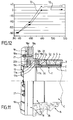
- FIGS 1, 2 and 3 illustrate the configuration of the ends E of T. section
- a section T comprises a first pipe 1, cylindrical shape and circular section.
- This first pipe 1 is waterproof and made of a low coefficient of expansion material. It can by example be made of Invar especially available from the Imphy Alloys company.
- the first pipe 1 passes the transported fluid, which is preferentially liquefied gas in its light 7. It constitutes a first sealing barrier vis-à-vis the fluid transported.
- a primary insulation layer 2 surrounds the first pipe 1 at its outer surface.
- This primary insulation layer 2 is less extended longitudinally than the primary pipe 1. It consists of a low thermal conductivity material that is less than 20.10 -3 Wm -1 .K -1 at room temperature.
- This material may for example be an airgel whose thermal conductivity is less than 16 ⁇ 10 -3 Wm -1 .K -1 at -160 ° C.
- the airgel used in this insulating layer 2 is in the form of balls. Suitable airgel beads are available from CABOT corporation.
- O-shaped obstruction devices 8 occupy the end of the primary insulation layer 2, at the level of each end E of the sections T.
- the primary layer 2 comprises longitudinally pairs of bars spacers 14 spaced apart in the azimuthal direction. These bars 14, according to FIGS. 4 and 5, are spaced at an angle substantially equal to 90 ° and are located on both sides of the lower generating line of the primary layer of insulation 2.
- each section T five pairs of spreader bars. 8 and the spacer bars 14 are preferentially made of a material of thermal conductivity close to that of the airgel of layer 2 and permeable to gases. This material can for example, a phenolic foam or a polyurethane foam.
- the spacer bars 14 may be spaced apart by angle and may vary in number, size, shape and disposition in the azimuthal plane. It can also be envisaged that these spacer bars 14 are in the form of a single alignment length of cleats at the level of the lower generating line of the primary layer of insulation 2.
- the primary layer of insulation 2 serves to limit the contributions of heat from the outside to the first pipe 1.
- the obstruction devices 8 make it possible to confine the balls airgel in the primary insulation layer 2.
- a first device 8 is placed at one end of the primary layer insulation 2 to form a tight vessel.
- a second device 8 is placed at the other end of the primary layer insulation 2 after having filled the latter with airgel balls.
- the support of the first pipe 1 by the second pipe 3 is provided by at least one spacer bar present in the layer primary insulation 2, ie the pairs of spacer bars 14 in the example shown. Indeed, said spacer bars 14 allow to transmit the weight of the first pipe 1 to the second pipe 3 without damage to the primary insulation layer 2.
- the obstruction devices 8 are preferably permeable to the gases which makes it possible to circulate an inerting gas, which may be nitrogen, within the primary insulation layer 2, to avoid the formation of an explosive mixture due to the contacting of the fluid transported with air in the event of leakage of the first pipe 1.
- Inerting gas sweeping of the primary layer isolation 2 can be performed by injecting dinitrogen to one of the ends of the primary insulation layer 2.
- the flow of gas inert can be done by pressurizing at one end of the primary layer of insulation 2 and draw to another.
- the inerting of the layer primary insulation 2 may allow control of the gas present in this layer 2 and therefore the detection of a possible leak.
- each obstruction device 8 is crossed longitudinally by eight holes 9. These holes 9 are plugged by a permeable material. However, if the obstruction devices 8 are permeable to gases, the holes 9 are then optional.
- the holes 9, whose number and layout may vary in the devices 8 and clogged with a gas-permeable material, such as bonded glass fabrics, serve the purpose of facilitating the flow of gas inerting while not letting out the primary layer insulation 2, ie the airgel balls.
- the second pipe 3 is made of the same material and has the same thickness as the first pipe 1. It differentiates from the first pipe 1 by the fact that it is less longitudinally than the first pipe 1 at each end E. It can also be seen that the second pipe 3 has the same length as the underlying primary insulation layer 2. This implies that a corresponding release is planned between the first pipe 1 and the second pipe 3.
- This second pipe 3 also constitutes a sealing barrier vis-à-vis the fluid transported in case of invasion of the layer primary insulation 2 by gas as a result of a leakage of the first pipe 1.
- the second pipe 3 also plays a role in reducing the contraction of the pipe C compared to conventional pipes. In effect, being made of a material with a low coefficient of expansion such that the Invar as the first pipe 1, it expands much less than any other metal and, like the first pipe 1, avoids the installation of means for compensating the expansion stresses, for example compensators in lyre or bellows.
- a secondary insulation layer 4 surrounds the second pipe 3.
- This secondary insulation layer 4 consists of two superimposed layers, the inner layer 41 and the outer layer 42. They consist of a material with a low thermal conductivity which can for example be a nano-porous material in airgel, preferably in textile form of thermal conductivity of 12.10 -3 Wm -1 .K -1 to -160 ° C. This material will also be advantageously permeable to gases.
- An appropriate airgel fabric is available in particular from ASPEN aerogels.
- Each inner 41 or outer 42 layer consists of two half-shells similarly to the layers 141 and 142 shown in Figure 9. In a particular example, the thickness of the inner insulation layer 41 is 19.2 mm and that of the outer layer 42 of 22.4 mm.
- the half-shells forming the outer layer 42 are dimensioned, in particular thickness, so as to accommodate a hollow sheath 15 of circular section which passes longitudinally along the length of the section T, at the lower junction of the two half-shells constituting the layer. external 42.
- This sheath 15 is intended to house an optical fiber or any other leak detection and localization system.
- the sheath 15 has a tapered flared end 16a which connects with the other end 16b of the sheath 15 of an adjacent T-section.
- the secondary insulation layer 4 is less extended longitudinally than the second pipe 3. This implies that an additional clearance is provided between the secondary insulation layer 4 and the second pipe 3.
- the secondary insulation layer 4 may be constituted a different number of layers, be made of another material or not to accommodate, in its thickness, a sheath 15 for optical fiber.
- the secondary insulation layer 4 serves to limit the contributions of heat from the outside environment to the second pipe 3. It is also used to thermally isolating the outside of the second pipe 3 and avoids a excessive cooling of the outer protective shell 6 in case Invasion of the primary insulation layer 2 by liquefied gas following a leak of the first pipe 1.
- the secondary layer insulation 4 is preferably gas permeable. This implies that it is also possible to circulate an inerting gas, which may be nitrogen, within this insulation layer 4 for a purpose similar to that previously described for the insulation layer 2.
- the optical fiber, not shown, preferentially placed in the sheath 15 is part of a leak detection device. These measures leak detection and localization is a linear sensor of DTS (distributed temperature sensor) temperature used to detect and locate any abnormal cold spot within the layer external 42 due to a possible leak of liquefied gas.
- the optical fiber is placed in the sheath 15 once the pipe C is assembled. She can be pulled along the pipe with an aramid fiber per example, or can be pushed with compressed air. It can be replaced in the same way as it was introduced, without intervention on driving C, for example by pulling it with the same aramid fiber along the pipe. We can also consider set up such a leak location device at the junction sections.
- the positioning of the optical fiber is preferable in the outer layer 42 of the secondary insulation layer 4 for several reasons. First, at this location, in the event of a possible leak, the optical fiber detects significant amplitude variations and it does not not undergo thermal cycles that are too loose and could affect its operation. Finally, at this positioning, the amplitude of the signal of the optical fiber remains acceptable despite the low temperature.
- the protective envelope 6 is provided, at the level of its upper generative line, lifting devices 61.
- the lifting devices 61 are in the form of a bar of length less than that of the section T, arranged in the longitudinal direction of the T-section and midway between E-ends. Lifting devices 61 are traversed transversely orifices 62.
- the protective envelope 6 is made of steel with extra thickness and anti-corrosion coating to limit corrosion by seawater. The extra thickness allows also to protect the pipe C from external shocks.
- Lifting devices 61 when to them, allow driving C to be lifted and manipulated through their orifices 62.
- the protective envelope 6 is less extended longitudinally than the secondary layer of insulation 4, this creating a clearance additional between the outside of line C and the secondary layer insulation 4.
- a protective film 13 may be placed around the layer secondary insulation 4 to prevent its invasion by concrete.
- a concrete coating 5 is poured and fills the tubular space between the central part of the pipe (pipe 1, insulation 2, pipe 3, insulation layer 4 and any protective film 13) and the protective envelope 6.
- a hollow conduit 12 is disposed in the longitudinal direction and over the entire length of the section T. This hollow conduit 12 may have a circular section.
- the concrete coating 5 makes it possible to give a total density of vacuum pipe greater than that of seawater so that the pipe C naturally rests on the bottom of the water in the empty state (density of the concrete charged with the order of 3).
- the apparent mass of the submerged pipe must be greater than 10 kg per meter. This limits the movements experienced by the conduct C and therefore its damage.
- the hollow conduit 12 allows not only to purge the infiltration of seawater into the coating of concrete 5 as a result of a possible leakage of the protective envelope 6 which surrounds it, but still to evacuate the water resulting from the drying of poured concrete and optionally also to circulate an inert gas.
- the hollow duct 12 has the function drying or ventilation of the pipe.
- the protective film 13 possibly placed around the layer secondary insulation 4 has the function of protecting the latter from invasion by the concrete slag 5 when poured into the envelope 6. It must also protect the secondary layer of insulation 4 the abrasive effect of the concrete coating 5 and the possible friction between the secondary insulation layer 4 and the concrete coating 5 due to differences in thermal contraction during the passage of liquid gas.
- Line C is formed of sections T connected end to end with level of the ends E.
- the sections T measure for example four meters long. They are connected end to end to form a pipe C of the desired length, for example about 5000 m.
- the length sections T and their number can obviously vary according to the applications.
- the different elements composing a section T present, with respect to other, a longitudinal extension which is reduced in the radial direction towards outside.
- This staged structure of the ends E of the section T allows to facilitate the welding operations of the different sections T between them. Indeed, this structure creates clearances that facilitate access to the deepest structures such as the first pipe 1. The clearance thus created will also allow the supply of parts reported for welds and positioning of layers of insulation materials at the fittings.
- the first pipes 1 of the two adjacent sections T1 and T2 are welded end to end by a weld seam.
- the inner 121 and outer 122 layers primary insulation are each formed of a pair of half-shells, represented in FIG. 9, made of insulating material, for example in textile form that can be airgel. Junction plans of two pairs of half-shells are perpendicular to each other.
- the second pipes 3 of the two sections T1 and T2 are welded together by means of patches which are, according to the method of illustrated embodiment, in the form of half-shells 103, but which can also be in the form of a split ring.
- Both half-shells 103 in Invar are welded tightly to the second pipes 3 by peripheral welding seams and to each other by longitudinal weld seams.
- Layers internal 141 and external secondary insulation 142 have the same constitution that the inner 121 and outer 122 layers of insulation primary school mentioned above.
- the outer layer 142 of insulation secondary passes the sheath 15 at the lower joint of his two half-hulls. Moreover, the sheath 15 of the optical fiber is slid into this joint after welding the half-shells 103 to not interfere with this weld.
- each half-shell 105 is traversed longitudinally by a hollow conduit 112 at its generator line.
- the hollow conduit 112 of the half-shell lower part makes it possible to connect the hollow conduits 12 of the sections T1 and T2 successive.
- a protective film 13 which is not shown in FIG. 9 can optionally be reported between the secondary layers insulation 104 and the half-shells of concrete 105.
- the protective envelopes 6 of the two sections T1 and T2 are connected by means of an external insert which is advantageous, in the form of a split ring 106 matched to the tube adjacent 6 of larger diameter.
- Split ring 106 is brought longitudinally along one of the sections up to the level of the connection to be welded to the ends of the protective shells 6 of the adjacent T1 and T2 sections by two peripheral weld seams waterproof.
- the inner diameter of the first pipe 1 is 800 mm and its thickness of 3 mm. The inside diameter is justified by the first load loss estimates.
- the thickness of the first pipe 1 has been sampled at 3 mm depending on the pump stop pressure of an LNG tanker admitting a constraint equal to 66% of the limit elastic.
- the thickness of the primary insulation layer 2 is 40 mm.
- the second pipe 3 has an external diameter of 892 mm and is less extensive longitudinally that the first pipe 1 of 150 mm at the level of each end E.
- the secondary layer 4, also of a thickness of 40 mm is less longitudinally than the second pipe 3 of 100 mm level of each end E.
- the protective envelope 6 has a thickness of approximately 16 mm.
- the concrete coating 5 has a thickness of about 55 mm and the hollow conduit 12 has a diameter of about 40 mm.
- the length of the first pipe 1 is 4000 mm, that of the primary insulation layer 2 and the second pipe 3 of 3700 mm, that of the secondary insulation layer 4, the film of protection 13, and the protective envelope 6 of 3500 mm and that of the concrete coating of 3480 mm.
- a terminal is now described. in which the C pipe described above is used for the transport of liquefied gas between a loading station and unloading P and an installation on land I.
- the number 75 designates the sea level.
- the loading and unloading station P has a movable arm 71, a platform 24 supported by pillars 70, which supports the movable arm 71.
- a fixed tower 25 of concrete is constructed under the platform 24.
- the movable arm 71 carries a sleeve (not shown in Figure 10) that can connect to the pipes loading / unloading a LNG carrier according to the known technique.
- the movable arm 71 is connected to a connecting pipe 23 which extends between the platform 24 and the bottom of the water F inside the fixed tower 25.
- the connecting pipe 23 is connected to the pipe C by a fixed abutment piece B embedded in the concrete 26.
- Loading and unloading station P via of its swiveling arm 71 which adapts to all the templates of LNG carriers, allows the loading or unloading of the LNG carrier (no represented) in cash.
- the shore installation I also comprises a connection pipe 23a which is connected to liquefied gas storage tanks (no represented) and which extends to the bottom of the water F within a fixed tower 25a.
- the connecting pipe 23a is also connected to the pipe C by a fixed abutment piece B embedded in the concrete 26.
- the non-submerged connecting pipes 23 and 23a can be designed according to the known technique, for example in the form stainless steel pipes with adequate insulation compensation systems.
- the ends of the pipe C are anchored to stop pieces stationary B at a loading or unloading station P and of an installation on land I.
- the pipe C which connects the loading and unloading station P and the shore facility I rests on the bottom of the water F. It allows the transfer of the liquefied gas between the loading or unloading station P and the installation on land I over a large distance, for example 5 km, which allows to place the post P at a great distance from the coast.
- Two ducts C sized according to the example above can transport the liquefied gas at a rate of 6000 m 3 / h, which allows the transfer of a cargo of a methane tanker of 144,000 m 3 in twelve hours.
- a line C according to the invention can also be provided between the loading and unloading station P and the shore installation I for conveying gas in vapor form.
- She is functionally different but physically identical to the two aforementioned pipes, which carry liquefied gas.
- This pipe serves, during unloading of the LNG carrier, to be transported to the LNG tanker, the volume of gas in vapor form needed to replace the gas volume liquid that we discharge.
- the laying of pipe C includes the steps of pre-assembly on land sections T, then assembly at sea pre-assembled sections T and connection of line C to fixed stop pieces B.
- a pre-assembly of 4 meter sections T in sets of 40 to 60 meters for example can be done.
- the assembly of the sections T pre assembled from 40 to 60 meters can be considered from a barge
- the barge must be equipped with a stinger in order to support the portion of line C suspended between the bottom of the water F and the barge.
- An installation from the ground can also be considered.
- Each fixed stop piece B is composed of different elements which are: an internal flange 17, an external flange 18 and a cover 19.
- the internal flange 17 comprises a pipe 17b whose inner surface has a shoulder 17c and the outer surface has a flange radially projecting peripheral 17a.
- the outside diameter is descending from flange 17a towards end turned towards the cover 19.
- the outer flange 18 has three parts: a pipe 18b, a radially outer peripheral edge 18a at its end facing towards the cover 19 and a radially inner annular flange 18c between the two ends of the pipe 18b.
- the inside diameter of the annular flange 18c corresponds substantially to the outside diameter of the portion of the pipe 17b located between the flange 17a and the end facing the C.
- the outer flange 18 has a series of threaded studs 18d disposed on the face of the flange 18a turned towards the cover 19.
- the outer diameter of the outer flange 18 is slightly decreasing in the portion between the flange 18a and the end S3 connected with the protective envelope 6 of the pipe C
- the cover 19 has substantially the shape of a disc crossed longitudinally by orifices 19b arranged on a circle concentric to the axis of revolution of the lid.
- the lid 19 also has a central opening 19c whose diameter corresponds substantially to the outer diameter of the pipe 17b.
- Lid 19 also has ribs 19a protruding on its opposite side to the external flange 18 which promote heat exchange on the one hand and stiffen the lid 19 on the other hand.
- concrete 26 surrounds the outer surface of pipe 18b and the end E of the pipe C connected to it.
- the end E of the pipe C is assembled to the stop piece fixed B preferentially out of the water, then the whole is immersed after setting up a plug to be fixed in the concrete. All first, the end E of the pipe C is driven into the light of the pipe 17b of the inner flange 17 without reaching the shoulder 17 c.
- the end of the first pipe 1 is welded to the inner surface of the pipe 17b between the end S1 and the shoulder 17c.
- the second pipe 3 is when to it welded to the outer surface of the pipe 17b between the S2 end and the radially inner flange 18c of the outer flange 18, the thickness of the pipe 17b on this portion corresponding exactly to the thickness between the first pipe 1 and the second pipe 3.
- An insulating element 22 is placed in the space defined between the rim 18c and the end of the secondary insulation layer 4 and the coating The insulating element 22 extends the insulation of the secondary layer 4 insulation and concrete coating 5 within the external flange 18.
- the internal flange 17 is positioned longitudinally with respect to the external flange 18 by interposing a first positioning wedge 20a between the radially inner flange 18c and the flange radially 17a of the inner flange 17.
- a weld is performed at the end S3 solidarisant the protective envelope 6 and the flange external 18.
- a second positioning wedge 20b is placed against the flange 17a opposite the first positioning wedge 20a.
- the cover 19 is then placed against the second wedge of positioning 20b and the radially outer rim 18a engaging the studs 18d through the orifices 19b. Then the lid 19 is maintained in support by nuts 21 screwed on the studs 18d. The cover 19, bearing against the wedge 20b, ensures the immobilization of the internal flange 17 in the outer flange 18.
- the mounting of the fixed stop B can also be envisaged under the water.
- the pipe C is able to be extended between the loading and unloading stations P and the installation at I without providing retraction compensation devices thermal.
- B fixed stop parts are designed and set so as to withstand thermal contractions due to transport of liquefied gas.
- the fixed stops B then constitute elements of recovery of thermal forces.
- Tensile forces due to cold setting of pipes 1 and 3 and possibly cooling of the outer protective shell 6 - the temperature of which follows that of the surrounding environment - are partially compensated - during the unloading - by the background effect corresponding to the pressure drop in the pipe 1 applied to the passage section.
- constraints due to the background effect are small compared to those due to the retraction of materials.
- Table 1 in the appendix gives an example of submarine conduct S design at a depth of 35 m.
- the internal sizing pressure used is 1.5 times pressure the stop pressure of the pumps of the LNG tanker who is repressing the liquid say 15 bars. This pressure of 15 bar is intended to be supported by the first pipe 1, and possibly the second pipe 3 which must resist this pressure if the first pipe 1 gives way.
- the envelope protective 6 must withstand twice the immersion pressure that is to say about 7 bars.
- the internal pressure of the protective envelope 6 under water is the atmospheric pressure because the space between the pipe 3 and the envelope 6 communicates with the atmosphere through the stop piece B. Its external pressure, due to immersion under 30 m of water and 5 m of tidal range is around 3.5 bars.
- the minimum thicknesses eMin calculated to withstand the pressure internal level at each pipe is 1.49 mm for the first pipe 1 and 1.75 mm for the second pipe 3.
- the minimum thickness provided for the protective casing 6 is 2.63 mm when conducting It is submerged at 30 m under water.
- the temperature profile in the thickness of line C according to the above numerical example used for the transport submarine of liquid methane, is shown in FIG. diagram represents the service temperature (in ° C) as a function of distance from the center of line C (in mm).
- the service temperature is the temperature within the different elements driving during the transport of liquid gas.
- Curve 72 represents the case where the temperature outside line C is 4 ° C.
- the curve 73 represents the case where the temperature outside line C is 30 ° C.
- the two curves show the same general evolution.
- the temperature increases from the center of the pipe C towards the outside.
- Each curve is composed of six points.
- the first point of each curve, at a temperature of about -160 ° C represents the temperature at inside the first pipe 1, the second point: the one outside the first pipe 1, the third point: that inside the second pipe 3, the fourth point: the one outside the second pipe 3, the fifth point: the one outside the concrete coating 5 and the sixth point: the one outside the protective envelope 6, ie that of the surrounding marine environment.
- the temperature gradient is important. This means that the primary layer insulation 2 plays well its role of thermal insulation.
- the temperature is about -100 ° C for the first curve 72 and -85 ° C for the second 73. It is found that the temperatures at the second pipe 3 are still very cold.
- a second embodiment of driving is now described C, in which the thermal effects of retraction of the first pipe 1 or second pipe 3 during the transport of liquefied gas are taken up by compensation mechanisms along line C.
- the structure of the sections T according to the second embodiment is identical to that of the sections T according to the first embodiment.
- the structure of the sections T according to the second embodiment is therefore illustrated by Figures 1 to 5.
- Line C according to the second embodiment comprises connections between sections which differ from the connections of the first mode of realization because they include compensation systems the thermal contraction 30 interconnecting the first pipes 1 and / or the second pipes 3.
- a thermal contraction compensation system 30 is partially shown in FIG. 13.
- This is a sleeve 31 tubular which has at its two ends, a diameter corresponding to the external diameter of the first pipes 1 or second pipes 3 to be connected.
- This last feature allows at the sleeve 31 to accommodate the ends of the first pipes 1 or second pipes 3.
- the ends 34 of the sleeve 31 are then welded by a peripheral weld seam sealed to the surface of the first 1 or second pipes 3.
- the sleeve 31 connects first two pipes 1 or second pipes 3 belonging to two sections T1 and T2 adjacent.
- the sleeve 31 is made of a material allowing a assembly adapted by gluing or welding, for example, to pipes 3 adjacent. It has at least one peripheral radial corrugation 32 in accordion shape in its central position, ie three ripples 32 in the example shown.
- the structure formed by the waves 32 stretches and settles at will deformations of the corresponding pipe due to temperature variations.
- the sleeve 31 is therefore an element of local recovery effects thermal.
- the compensation of the thermal contraction 30 are arranged straddling the second pipes 3 of two adjacent sections T1 and T2 that is to say at the place of the inserts 103 of the first embodiment and / or between the first pipes 1.
- the other elements making up the connection are identical to those of the first embodiment.
- the second embodiment of line C is advantageous in that it allows the first 1 and / or the second 3 pipes to be Made of material that does not have a low coefficient of expansion unlike the first embodiment, for example steel stainless steel, in various alloys or in composite materials. It results an economic advantage.
- the compensation systems are used in stainless steel pipes or other expandable material.
- the pipes not made of a material of low coefficient of expansion retract longitudinally intensely when cold setting which, in the absence of appropriate compensation, could consequence the tearing of the anchoring of the ends of the pipe C or the proper tearing of the pipe if the anchorage was resistant to these constraints.
- fittings according to FIGS. 7 to 9 can also be used alternately with compensation systems 30.
- the structure of fittings without compensation 30 is then identical to that of the first mode of realization, except that the pair of half-shells 103 to weld the second pipe 3 is of a material not necessarily low expansion thermal, but compatible with the assembly mode.
- the ends of the pipes C according to the second mode of realization can also be anchored by fixed stops B at a post loading and unloading P and to an onshore installation I of identical to that of the first embodiment in reference in Figures 10 and 11.
- the driving may differ described in the preceding embodiments by the fact that it comprises a second pipe 3 made of composite material.
- the ends of the second pipes 3 adjacent are then connected by a joint cover 203 of material flexible composite, for example the Triplex (registered trademark), whose ends 204a overlap and are adhered to the outer surface of the ends of the second pipes 3 adjacent.
- the composite material consists for example of a resin polymer reinforced with fibers, for example a polyester or epoxy resin reinforced with fiberglass or carbon, possibly woven.
- the composite material may be further composed so as to present mechanical properties satisfying the criterion: Re> E. ⁇ . DT.
- Triplex is a material with three layers, namely two outer layers of fiberglass fabrics and an intermediate layer Thin metal sheet.
- the Triplex is notably marketed by the company Hutchinson.
- second pipes 3 of composite material allows a significant reduction in the cost of manufacturing pipes.
Abstract
Description
La présente invention concerne une conduite thermiquement isolée destinée notamment au transport de gaz naturel liquéfié, notamment sous-marin, son utilisation et un terminal maritime comportant une telle conduite.The present invention relates to a thermally insulated conduit intended in particular for the transport of liquefied natural gas, in particular submarine, its use and a marine terminal incorporating such conduct.
On connaít l'utilisation de conduites en Inox ou en alliage de nickel qui permettent de transporter du gaz liquéfié en surface entre un méthanier à quai et un réservoir de stockage terrestre. Lorsque ces conduites sont mises en service, le refroidissement des conduites de la température ambiante à une température très basse, par exemple -162°C pour le méthane liquide à pression normale, s'accompagne d'une rétraction des matériaux constituant la conduite. Des mécanismes de compensation de la rétraction thermique, sous forme de lyre, c'est à dire une portion de tuyau s'écartant latéralement en forme de U ou de compensateur, c'est à dire une portion de tuyau ondulée à la manière d'un soufflet, sont prévus pour éviter que la rétraction brutale n'endommage les conduites.We know the use of stainless steel pipes or alloy of nickel which can transport liquefied gas at the surface between a LNG tanker and a land storage tank. When these pipes are put into operation, the cooling of the pipes of the ambient temperature at a very low temperature, for example -162 ° C for liquid methane at normal pressure, is accompanied by a retraction of the materials constituting the pipe. Mechanisms of compensation for the thermal shrinkage, in the form of a lyre, ie a portion of pipe laterally diverging in a U-shape or compensator, ie a portion of corrugated pipe in the manner a bellows, are provided to prevent the abrupt retraction does not damage the pipes.
En outre, la conduite doit nécessairement comprendre une isolation thermique pour éviter le réchauffement du gaz liquéfié et ainsi limiter sa vaporisation.In addition, the driving must necessarily include a thermal insulation to prevent the liquefied gas from heating up and so limit its vaporization.
On connaít par la demande de brevet français FR-A-2 748 545 une conduite thermiquement isolée pour le transport de gaz naturel liquéfié. Cette conduite comprend deux tubes coaxiaux, un isolant thermique emplissant l'espace tubulaire compris entre ces tubes sous vide industriel contrôlé ainsi qu'un enrobage extérieur de béton faisant office de lest. Le tube externe est constitué d'acier alors que le tube interne est réalisé en Invar.French patent application FR-A-2 748 545 discloses a thermally insulated conduit for the transport of liquefied natural gas. This pipe includes two coaxial tubes, thermal insulation filling the tubular space between these industrial vacuum tubes controlled as well as a concrete outer coating serving as ballast. The outer tube is made of steel while the inner tube is made of Invar.
Sur les conduites lestées classiques, si le lest extérieur vient à se briser, la canalisation est localement moins dense que l'eau et se soulève du fond. Ce phénomène une fois initié se propage spontanément le long de la conduite qui cède alors ou remonte à la surface.On conventional weighted lines, if the external ballast comes to break, the pipeline is locally less dense than water and rises the bottom. This phenomenon once initiated spreads spontaneously along of the pipe which then yields or rises to the surface.
On connaít par ailleurs par la demande de brevet français FR-A-2 746 891 une conduite thermiquement isolée pour le transport de produits pétroliers. Cette conduite comprend deux tubes coaxiaux et un isolant thermique emplissant partiellement l'espace tubulaire compris entre ces deux tubes sous vide industriel contrôlé. Also known from the French patent application FR-A-2 746 891 a thermally insulated pipe for the transport of oil products. This pipe comprises two coaxial tubes and one thermal insulation partially filling the tubular space included between these two tubes under controlled industrial vacuum.
L'invention a pour but de proposer une nouvelle conduite thermiquement isolée qui présente de nombreuses qualités. En particulier, l'invention a pour but de fournir une conduite offrant un haut niveau d'isolation thermique et de sécurité de fonctionnement.The invention aims to propose a new driving thermally insulated which has many qualities. In particular, the invention aims to provide a pipe with a high level of thermal insulation and operational safety.
A cet effet, l'invention a pour objet une conduite thermiquement isolée comprenant de l'intérieur vers l'extérieur :
- un premier tuyau étanche,
- une première couche d'isolation thermique,
- un second tuyau étanche,
- une seconde couche d'isolation thermique en matériau isolant,
- un lest en matériau de densité supérieure à celle de l'eau de mer,
- a first sealed hose,
- a first layer of thermal insulation,
- a second waterproof pipe,
- a second layer of thermal insulation made of insulating material,
- a ballast material with a density higher than that of seawater,
La double couche d'isolation permet de minimiser l'amplitude des cycles thermiques subis par le second tuyau tout en conservant une seconde isolation capable d'isoler thermiquement le lest de béton et l'enveloppe d'acier d'un éventuel envahissement de la première isolation par le liquide.The double layer of insulation minimizes the amplitude of thermal cycling undergone by the second pipe while maintaining a second insulation capable of thermally isolating concrete ballast and the steel casing of a possible invasion of the first insulation by the liquid.
Grâce à la superposition des deux tuyaux et de l'enveloppe protectrice, pour cette application comme pour d'autres applications industrielles analogues, la présente invention apporte une sécurité accrue de l'installation.Thanks to the superposition of the two pipes and the envelope protective, for this application as for other applications similar industrial designs, the present invention provides increased security of the installation.
Même en cas de fracture du lest, celui-ci est maintenu par l'enveloppe et le poids apparent de la conduite s'en trouve inchangé, ce qui empêche que la conduite remonte ou se brise.Even in case of ballast fracture, it is maintained by the envelope and the apparent weight of the pipe are unchanged, this which prevents the pipe from rising or breaking.
Préférentiellement, au moins un élément du groupe constitué par le
premier tuyau, le second tuyau et l'enveloppe protectrice présente des
caractéristiques mécaniques telles que :
- où E est le module d'élasticité du matériau constitutif,
- α est le coefficient de dilatation thermique du matériau constitutif,
- ΔT est la différence entre la température de service dudit élément et la température ambiante,
- et Re est la limite élastique du matériau à la température de service dudit élément.
- where E is the modulus of elasticity of the constituent material,
- α is the coefficient of thermal expansion of the constituent material,
- ΔT is the difference between the operating temperature of said element and the ambient temperature,
- and Re is the elastic limit of the material at the service temperature of said element.
Ces caractéristiques permettent, pour l'élément correspondant, de se passer éventuellement, de système de compensation de la contraction thermique. Ainsi pour le transport de gaz liquide, comme pour d'autres applications industrielles analogues, la présente invention propose une méthode particulièrement simple de rattrapage de la dilatation thermique.These characteristics make it possible, for the corresponding element, to possibly happen, contraction compensation system thermal. Thus for the transport of liquid gas, as for other analogous industrial applications, the present invention proposes a particularly simple method of catching up thermal expansion.
Avantageusement, les deux tuyaux présentent ces caractéristiques.Advantageously, the two pipes have these characteristics.
De manière avantageuse, au moins l'un desdits tuyaux étanches est constitué d'un alliage à haute teneur en Nickel. Ces alliages, comme par exemple l'Invar, permettent d'obtenir les caractéristiques mécaniques ci-dessus.Advantageously, at least one of said sealed pipes is consisting of an alloy with a high nickel content. These alloys, as example the Invar, allow to obtain the mechanical characteristics above.
Selon un mode de réalisation, le second tuyau étanche est réalisé en matériau composite à base de résine polymère. L'utilisation d'un tel matériau pour réaliser le second tuyau étanche engendre une réduction significative des coûts de fabrication de la conduite. De plus, les matériaux composites peuvent aussi être choisis de manière à présenter les caractéristiques mécaniques ci-dessus.According to one embodiment, the second sealed pipe is made composite material based on polymer resin. The use of such material for making the second watertight pipe generates a reduction significant manufacturing costs of the pipe. Moreover, the composite materials can also be chosen to present the mechanical characteristics above.
Avantageusement, les deux tuyaux et l'enveloppe externe satisfont ce critère, ce qui permet de réaliser une conduite éventuellement dépourvue de tout système de compensation de la contraction thermique.Advantageously, the two pipes and the outer casing satisfy this criterion, which makes it possible to carry out a possible devoid of any compensation system for thermal contraction.
Selon un autre mode de réalisation particulier, au moins l'un desdits tuyaux est muni d'au moins un système de compensation de la contraction thermique. Un tel système permet d'améliorer la reprise des effets thermiques.According to another particular embodiment, at least one said pipes is provided with at least one compensation system of the thermal contraction. Such a system makes it possible to improve the recovery of thermal effects.
Préférentiellement, ledit système de compensation de la contraction thermique se présente sous forme d'un manchon comprenant au moins une ondulation radiale.Preferably, said compensation system of the thermal contraction is in the form of a sleeve comprising at least one radial corrugation.
De manière préférentielle, au moins un élément du groupe constitué par le premier tuyau, le second tuyau et l'enveloppe protectrice est ancré au niveau de ses extrémités à des butées fixes assurant la reprise des contraintes thermiques subies par ledit élément.Preferably, at least one member of the group consisting of the first pipe, the second pipe and the protective shell is anchored at its ends to fixed stops ensuring the recovery of thermal stresses on said element.
Avantageusement, le lest est constitué d'un matériau apte à être coulé sous une forme liquide, pulvérulente ou granulaire dans le volume cylindrique compris entre la seconde couche d'isolation et l'enveloppe protectrice. Préférentiellement, ledit lest comporte du béton à l'intérieur de l'enveloppe protectrice. Le béton est en effet facile à couler, l'enveloppe servant de moule. De plus, le béton est alors protégé du milieu extérieur par l'enveloppe d'acier, conférant à l'assemblage une bonne tenue au chocs ainsi qu'une parfaite étanchéité.Advantageously, the ballast consists of a material capable of being poured in a liquid, powdery or granular form into the volume cylindrical between the second layer of insulation and the envelope protective. Preferably, said ballast comprises concrete inside of the protective envelope. Concrete is easy to pour, the envelope serving as a mold. In addition, the concrete is then protected from external environment by the steel casing, conferring on the assembly a good shock resistance and a perfect seal.
La constitution même du tuyau et le choix de la nature des matériaux contribuent à la réalisation et à l'exploitation aisée de l'invention. En effet, l'utilisation de béton permet de s'affranchir des contraintes d'assemblage rencontrées dans les techniques conventionnelles de réalisation. La coulée du béton dans une enveloppe d'acier permet également de tirer meilleur parti de la bonne résilience mécanique de l'acier et ainsi de réduire la sensibilité aux chocs de la conduite tout en permettant une inspection visuelle de l'enveloppe afin de détecter d'éventuels points de corrosion.The very constitution of the pipe and the choice of the nature of materials contribute to the achievement and easy operation of the invention. Indeed, the use of concrete makes it possible to get rid of assembly constraints encountered in the techniques conventional realization. Pouring concrete into an envelope of steel also helps to make better use of the good resilience mechanical steel and thus reduce the shock sensitivity of the conduct while allowing a visual inspection of the envelope so to detect possible points of corrosion.
De manière encore plus préférentielle, un film de protection est disposé entre le lest de béton et ladite couche secondaire d'isolation thermique. Le film de protection a pour rôle d'empêcher l'invasion du laitier de béton dans la couche secondaire d'isolation lors de la coulée.Even more preferably, a protective film is disposed between the concrete ballast and said secondary insulation layer thermal. The role of the protective film is to prevent the invasion of concrete slag in the secondary layer of insulation during casting.
De manière avantageuse, ledit lest comporte au moins un conduit creux ménagé dans ce dernier, qui peut servir à la ventilation ou à l'assèchement. Préférentiellement, le conduit creux est disposé dans le sens longitudinal et sur toute la longueur de ladite conduite. Le conduit creux permet en outre d'évacuer l'eau exsudée du béton lors du séchage ou de détecter une éventuelle intrusion d'eau de mer. Il permet éventuellement aussi de faire circuler un gaz inerte.Advantageously, said ballast comprises at least one duct hollow space in the latter, which may be used for ventilation or drying. Preferably, the hollow conduit is disposed in the longitudinal direction and the entire length of said pipe. The conduit recess also makes it possible to evacuate the water exuded from the concrete during drying or to detect a possible intrusion of sea water. possibly also to circulate an inert gas.
De manière préférentielle, au moins une des couches d'isolation thermique est en matériau présentant une conductivité thermique inférieure à 20.10-3W.m-1.K-1 à température ambiante, de préférence inférieure à 16.10-3W.m-1.K-1 à -160°C. Les aérogels répondent généralement à ce critère.Preferably, at least one of the thermal insulation layers is of material having a thermal conductivity of less than 20 × 10 -3 Wm -1 .K -1 at room temperature, preferably less than 16 × 10 -3 Wm -1 .K -1. at -160 ° C. Aerogels generally meet this criterion.
Avec une telle isolation, le vide industriel contrôlé n'est plus obligatoire pour assurer une isolation thermique satisfaisante, ce qui évite de prévoir des appareillages de dépressurisation et un dimensionnement spécifique des conduites nécessaires à la mise en place du vide industriel contrôlé. L'invention permet donc de s'affranchir du vide industriel contrôlé évoqué précédemment par l'emploi de matériaux isolants à haute performance, et simplifie ainsi la mise en oeuvre et l'exploitation de la conduite.With such insulation, the controlled industrial vacuum is no longer required to ensure satisfactory thermal insulation, which avoid the need for depressurization equipment and specific dimensioning of the pipes necessary for the installation controlled industrial vacuum. The invention therefore makes it possible to overcome controlled industrial vacuum evoked previously by the use of materials high-performance insulators, and thus simplifies the implementation and the operation of the pipe.
Avantageusement, au moins une des couches d'isolation thermique est en matériau nano poreux de type aérogel. Un aérogel est un matériau solide de faible densité qui a une structure extrêmement fine et fortement poreuse (jusqu'à 90%). Il peut par exemple être fabriqué à partir de plusieurs matériaux comprenant la silice, l'alumine, le carbure d'hafnium ainsi que des variétés de polymères. Sa structure nanométrique lui confère des propriétés uniques d'isolant thermique étant donné que le parcours moyen des molécules de gaz et donc le transport d'énergie et de masse en son sein sont réduits. Il offre une conductivité thermique deux à quatre fois inférieure à celle d'autres isolants de type solide ou mousse isolante par exemple.Advantageously, at least one of the insulation layers thermal is nano porous airgel type material. An airgel is a low density solid material that has an extremely fine structure and highly porous (up to 90%). It can for example be manufactured in from several materials including silica, alumina, carbide of hafnium as well as varieties of polymers. Its structure nanometer gives it unique properties of thermal insulation given that the average path of the gas molecules and therefore the transport of energy and mass within it are reduced. It offers a thermal conductivity two to four times lower than other insulators of the solid type or insulating foam, for example.
Selon un mode particulier de réalisation de l'invention, au moins une des couches d'isolation thermique est sous forme textile. Selon un autre mode particulier de réalisation de l'invention, au moins une des couches d'isolation thermique se présente sous une forme pulvérulente ou granulaire permettant sa coulée dans le volume destiné à l'accueillir. Par exemple, une telle couche d'isolation thermique peut être sous forme de billes. L'utilisation de matériaux pulvérulents ou granulaires permet de faciliter l'assemblage de la conduite, notamment en imposant des tolérances moins précises que dans les techniques antérieures de réalisation. En effet, ces matériaux autorisent un défaut de positionnement entre les tuyaux sans provoquer de discontinuité de l'isolation.According to a particular embodiment of the invention, at least one of the thermal insulation layers is in textile form. According to one another particular embodiment of the invention, at least one of the thermal insulation layers comes in a powdery form or granular allowing its flow into the volume intended to accommodate it. For example, such a thermal insulation layer may be in the form of of balls. The use of powdery or granular materials allows facilitate the assembly of the pipe, in particular by imposing less precise tolerances than in previous techniques of production. Indeed, these materials allow a defect of between the pipes without causing any discontinuity insulation.
Plus préférentiellement, cette ou ces couche(s) d'isolation sous une forme pulvérulente ou granulaire comporte(nt) au moins un tronçon obturé à ses(leurs) deux extrémités longitudinales par des dispositifs d'obstruction en matériau isolant. Ces dispositifs d'obstruction peuvent être perméables aux gaz. Ces dispositifs d'obstruction peuvent aussi être traversés longitudinalement par des trous qui sont éventuellement bouchés par des filtres perméables aux gaz, de type tissu de verre par exemple. La perméabilité au gaz permet d'effectuer un balayage à l'azote par exemple.More preferably, this or these layer (s) of insulation under a pulverulent or granular form comprises at least one section obturated at its (their) two longitudinal ends by devices obstruction in insulating material. These obstruction devices can be permeable to gases. These obstruction devices can also be traversed longitudinally by holes which are possibly clogged by gas-permeable filters, glass-fiber type by example. Gas permeability allows a nitrogen sweep for example.
De manière avantageuse, ladite couche d'isolation thermique sous forme pulvérulente ou granulaire comporte au moins une barre d'écartement en matériau isolant, d'épaisseur sensiblement égale à celle de ladite couche d'isolation thermique et disposée parallèlement à la dite conduite. Les barres d'écartement peuvent être perméables aux gaz.Advantageously, said thermal insulation layer under powdery or granular form has at least one bar spacing of insulating material, of a thickness substantially equal to that of said thermal insulation layer and arranged parallel to the said conduct. The spacer bars may be gas permeable.
Selon un mode particulier de réalisation de l'invention, un dispositif de détection des fuites, qui peut par exemple être une fibre optique, est disposé dans le sens longitudinal sur toute la longueur de ladite conduite entre le premier tuyau et l'enveloppe protectrice.According to a particular embodiment of the invention, a leak detection device, which may for example be a fiber optical, is arranged in the longitudinal direction over the entire length of said conduit between the first pipe and the protective envelope.
Avantageusement, la conduite est formée de tronçons préfabriqués pouvant être raccordés bout à bout. Au niveau de ces raccords, les couches d'isolation thermique sont avantageusement sous forme textile. L'enveloppe et les tuyaux étanches peuvent être raccordés à l'aide de pièces rapportées ou directement par un cordon de soudure.Advantageously, the pipe is formed of prefabricated sections can be connected end to end. At these connections, the Thermal insulation layers are advantageously in textile form. Envelope and watertight hoses can be connected using patches or directly by a weld seam.
Encore plus avantageusement, les tronçons présentent au moins une extrémité étagée, les éléments constitutifs desdits tronçons ayant une extension longitudinale décroissante les uns par rapport aux autres dans le sens radial vers l'extérieur. Cette configuration des tronçons ménage des dégagements facilitant leur assemblage.Even more advantageously, the sections have at least a stepped end, the constituent elements of said sections having a longitudinal extension decreasing with respect to each other in the radial direction towards the outside. This configuration of the household sections clearances facilitating their assembly.
L'invention fournit également une utilisation de la conduite ci-dessus pour le transport d'un fluide à basse température. Le fluide à basse température peut être par exemple du gaz liquéfié.The invention also provides a use of the above driving for transporting a fluid at low temperature. The fluid to low temperature can be for example liquefied gas.
Selon un certain mode de réalisation, on fait circuler un gaz d'inertage dans au moins une des couches d'isolation thermique. Cependant, la circulation de gaz inerte est proposée dans un mode de réalisation préféré pour éviter la formation d'un mélange explosif par la mise en contact du gaz issu d'une éventuelle fuite et de l'air qui serait compris dans l'isolation thermique. La circulation de gaz inerte peut être effectuée à une pression supérieure à la pression atmosphérique.According to a certain embodiment, a gas is circulated inerting in at least one of the thermal insulation layers. However, the circulation of inert gas is proposed in a mode of preferred embodiment to avoid the formation of an explosive mixture by the contacting the gas resulting from a possible leak and the air that would be included in thermal insulation. The circulation of inert gas can be carried out at a pressure above atmospheric pressure.
L'invention a également pour objet un terminal maritime pour le transport de gaz liquéfié caractérisé par le fait qu'il comprend un poste de chargement et de déchargement relié à une installation à terre par au moins une conduite selon l'invention, les extrémités de ladite conduite pouvant être ancrées à des butées fixes. L'installation à terre est par exemple un parc de stockage de gaz liquéfié.The invention also relates to a maritime terminal for the transport of liquefied gas characterized by the fact that it includes a station loading and unloading connected to an onshore installation by least one pipe according to the invention, the ends of said pipe can be anchored to fixed stops. The onshore installation is example a liquefied gas storage tank.
L'invention sera mieux comprise, et d'autres buts, détails, caractéristiques et avantages de celle-ci apparaítront plus clairement au cours de la description explicative détaillée qui va suivre, de plusieurs modes de réalisation de l'invention donnés à titre d'exemples purement illustratifs et non limitatifs, en référence aux dessins schématiques annexés.The invention will be better understood, and other purposes, details, characteristics and benefits of this will become clearer in course of the detailed explanatory description which will follow, of several embodiments of the invention given by way of purely illustrative and non-limiting, with reference to the schematic drawings attached.
Sur ces dessins :
- la figure 1 est une vue de côté, de l'extrémité d'un tronçon de conduite selon un premier mode de réalisation de la présente invention ;
- la figure 2 est une vue partielle en coupe longitudinale du tronçon de conduite selon la figure 1 selon l'axe II-II ;
- la figure 3 est une vue agrandie d'une région de la figure 2 désignée par III ;
- la figure 4 est une coupe transversale du tronçon de conduite de la figure 2 selon la ligne IV-IV ;
- la figure 5 est une vue agrandie d'une région de la figure 4 désignée par V ;
- la figure 6 est une vue en perspective d'un tuyau intérieur du tronçon de conduite de la figure 1 présentant les dispositifs d'obstruction et les barres d'écartement;
- la figure 7 une coupe transversale de la conduite selon le premier mode de réalisation au niveau d'un raccord entre deux tronçons de conduite ;
- la figure 8 est une vue partielle agrandie du raccord de la figure 7 en coupe longitudinale selon la ligne VIII-VIII ;
- la figure 9 est une vue en perspective éclatée des différents éléments rapportés pour constituer un raccord à l'extrémité d'un tronçon de conduite;
- la figure 10 est schéma représentant la configuration d'un terminal maritime de transport de gaz liquéfié comportant la conduite selon le premier mode de réalisation ;
- la figure 11 est une vue longitudinale en quart de coupe d'une extrémité de conduite de la figure 10 ancrée dans une butée fixe ;
- la figure 12 est un diagramme représentant un profil de température en différents points de la conduite de la figure 10 ;
- la figure 13 est une vue partielle en coupe d'un système de compensation de la contraction thermique dans une conduite selon un deuxième mode de réalisation de l'invention et
- la figure 14 est une vue partielle agrandie d'un autre mode de réalisation du raccord de la figure 7 en coupe longitudinale selon la ligne XIV-XIV.
- Figure 1 is a side view of the end of a pipe section according to a first embodiment of the present invention;
- Figure 2 is a partial longitudinal sectional view of the pipe section according to Figure 1 along the axis II-II;
- Fig. 3 is an enlarged view of a region of Fig. 2 denoted by III;
- Figure 4 is a cross section of the pipe section of Figure 2 along line IV-IV;
- Fig. 5 is an enlarged view of a region of Fig. 4 designated V;
- Figure 6 is a perspective view of an inner pipe of the pipe section of Figure 1 showing the obstruction devices and the spacer bars;
- Figure 7 a cross section of the pipe according to the first embodiment at a connection between two pipe sections;
- Figure 8 is an enlarged partial view of the connector of Figure 7 in longitudinal section along the line VIII-VIII;
- Figure 9 is an exploded perspective view of the various elements reported to form a connection to the end of a pipe section;
- Figure 10 is a diagram showing the configuration of a liquefied gas marine terminal including the pipe according to the first embodiment;
- Figure 11 is a longitudinal quarter sectional view of a pipe end of Figure 10 anchored in a fixed stop;
- Fig. 12 is a diagram showing a temperature profile at different points of the pipe of Fig. 10;
- FIG. 13 is a partial sectional view of a system for compensating the thermal contraction in a pipe according to a second embodiment of the invention and
- Figure 14 is an enlarged partial view of another embodiment of the connector of Figure 7 in longitudinal section along the line XIV-XIV.
En référence aux figures 1 à 6, on décrit maintenant un tronçon T
de la conduite C selon un premier mode de réalisation. Le tronçon T
présente une structure multicouche avec, de l'intérieur vers l'extérieur,
un premier tuyau étanche 1, une première couche d'isolation appelée
couche primaire d'isolation 2, un second tuyau étanche 3, une seconde
couche d'isolation appelée couche secondaire d'isolation 4, un film de
protection 13, un enrobage de béton 5 et une enveloppe protectrice 6.With reference to FIGS. 1 to 6, a section T is now described.
of the pipe C according to a first embodiment. The section T
has a multilayer structure with, from the inside to the outside,
a first
Les figures 1, 2 et 3, illustrent la configuration des extrémités E du tronçon T.Figures 1, 2 and 3 illustrate the configuration of the ends E of T. section
Selon la figure 2, un tronçon T comprend un premier tuyau 1, de
forme cylindrique et de section circulaire. Ce premier tuyau 1 est étanche
et constitué d'un matériau à faible coefficient de dilatation. Il peut par
exemple être constitué d'Invar notamment disponible auprès de la
société Imphy Alloys.According to FIG. 2, a section T comprises a
Le premier tuyau 1 laisse passer le fluide transporté, qui est
préférentiellement du gaz liquéfié dans sa lumière 7. Il constitue une
première barrière d'étanchéité vis-à-vis du fluide transporté.The
Une couche primaire d'isolation 2 entoure le premier tuyau 1 au
niveau de sa surface externe. Cette couche primaire d'isolation 2 est
moins étendue longitudinalement que le tuyau primaire 1. Elle est
constituée d'un matériau à faible conductivité thermique c'est à dire
inférieure à 20.10-3 W.m-1.K-1 à température ambiante. Ce matériau peut
par exemple être un aérogel dont la conductivité thermique est inférieure
à 16.10-3 W.m-1.K-1 à -160°C. Préférentiellement, l'aérogel utilisé dans
cette couche d'isolation 2 est sous forme de billes. Des billes d'aérogel
appropriées sont notamment disponibles auprès de la société CABOT
corporation.A
Des dispositifs d'obstruction 8 de forme torique occupent
l'extrémité de la couche primaire d'isolation 2, au niveau de chaque
extrémité E des tronçons T. O-shaped
Comme visible sur les figures 4, 5 et 6, la couche primaire
d'isolation 2 comporte longitudinalement, des paires de barres
d'écartement 14 espacées dans la direction azimutale. Ces barres 14,
selon les figures 4 et 5, sont espacées d'un angle sensiblement égal à 90°
et sont situées de part et d'autre de la ligne génératrice inférieure de la
couche primaire d'isolation 2. Selon la figure 6, chaque tronçon T
présente cinq paires de barres d'écartement 14. Les dispositifs
d'obstruction 8 et les barres d'écartement 14 sont préférentiellement
constitués d'un matériau de conductivité thermique proche de celle de
l'aérogel de la couche 2 et perméable aux gaz. Ce matériau peut par
exemple être une mousse phénolique ou une mousse de polyuréthane.As can be seen in FIGS. 4, 5 and 6, the
Par conséquent, il ne se forme pas de ponts thermiques entre le
premier tuyau 1 et les autres éléments du tronçon T.Consequently, no thermal bridges are formed between the
En variante, les barres d'écartement 14 peuvent être espacées d'un
angle différent et peuvent varier en nombre, en taille, en forme et en
disposition dans le plan azimutal. L'on peut également envisager que ces
barres d'écartement 14 se présentent sous forme d'un seul alignement
longitudinal de tasseaux au niveau de la ligne génératrice inférieure de la
couche primaire d'isolation 2.Alternatively, the spacer bars 14 may be spaced apart by
angle and may vary in number, size, shape and
disposition in the azimuthal plane. It can also be envisaged that these
spacer bars 14 are in the form of a single alignment
length of cleats at the level of the lower generating line of the
primary layer of
La couche primaire d'isolation 2 sert à limiter les apports de
chaleur du milieu extérieur vers le premier tuyau 1.The primary layer of
Les dispositifs d'obstruction 8 permettent de confiner les billes
d'aérogel dans la couche primaire d'isolation 2. Un premier dispositif
d'obstruction 8 est placé à l'une des extrémités de la couche primaire
d'isolation 2 afin de former un vase étanche. Un second dispositif
d'obstruction 8 est placé à l'autre extrémité de la couche primaire
d'isolation 2 après avoir rempli cette dernière des billes d'aérogel.The
Enfin, le soutien du premier tuyau 1 par le second tuyau 3 est
assurée par au moins une barre d'écartement présente dans la couche
primaire d'isolation 2, c'est à dire les paires de barres d'écartement 14
dans l'exemple représenté. En effet, lesdites barres d'écartement 14
permettent de transmettre le poids propre du premier tuyau 1 au second
tuyau 3 sans endommagement de la couche primaire d'isolation 2.Finally, the support of the
Les dispositifs d'obstruction 8 sont préférablement perméables
aux gaz ce qui permet de faire circuler un gaz d'inertage, pouvant être de
l'azote, au sein de la couche primaire d'isolation 2, permettant d'éviter la
formation d'un mélange explosif dû à la mise en contact du fluide
transporté avec de l'air dans le cas d'une perte d'étanchéité du premier
tuyau 1. Le balayage par le gaz d'inertage de la couche primaire
d'isolation 2 peut être effectuée par injection de diazote à l'une des
extrémités de la couche primaire d'isolation 2. La circulation du gaz
inerte peut être effectuée par pressurisation à une des extrémités de la
couche primaire d'isolation 2 et tirage à l'autre. L'inertage de la couche
primaire d'isolation 2 peut permettre un contrôle du gaz présent dans
cette couche 2 et par conséquent la détection d'une éventuelle fuite.The
Selon la figure 1, chaque dispositif d'obstruction 8 est traversé
longitudinalement par huit trous 9. Ces trous 9 sont bouchés par un
matériau perméable aux gaz. Cependant, si les dispositifs d'obstruction 8
sont perméables aux gaz, les trous 9 sont alors facultatifs. Les trous 9,
dont le nombre et la disposition peuvent varier dans les dispositifs
d'obstruction 8 et bouchés par un matériau perméable aux gaz, tel que du
tissus de verre collé, ont pour utilité de faciliter la circulation du gaz
d'inertage tout en ne laissant pas s'échapper la couche primaire
d'isolation 2, c'est à dire les billes d'aérogel.According to FIG. 1, each
Un second tuyau 3, également étanche et de section circulaire, est
disposé autour de la couche primaire d'isolation 2 coaxialement au
premier tuyau 1. Dans cet exemple de réalisation, le second tuyau 3, est
constitué du même matériau et présente la même épaisseur que le
premier tuyau 1. Il se différencie du premier tuyau 1 par le fait qu'il est
moins étendu longitudinalement que le premier tuyau 1 à chaque
extrémité E. L'on peut également constater que le second tuyau 3
présente la même longueur que la couche primaire d'isolation 2 sous-jacente.
Ceci implique qu'un dégagement correspondant est prévu entre
le premier tuyau 1 et le second tuyau 3.A
Ce second tuyau 3 constitue également une barrière d'étanchéité
vis-à-vis du fluide transporté en cas d'envahissement de la couche
primaire d'isolation 2 par du gaz à la suite d'une fuite du premier tuyau
1.Le second tuyau 3 joue également un rôle dans la diminution de la
contraction de la conduite C par rapport aux conduites classiques. En
effet, étant constitué d'un matériau à faible coefficient de dilatation tel
que l'Invar comme le premier tuyau 1, il se dilate beaucoup moins que
tout autre métal et, comme le premier tuyau 1, permet d'éviter
l'installation de moyens de compensation des contraintes de dilatations,
par exemple de compensateurs en lyre ou à soufflets.This
Une couche secondaire d'isolation 4 entoure le second tuyau 3.
Cette couche secondaire d'isolation 4 est constituée de deux couches
superposées, la couche interne 41 et la couche externe 42. Elles sont
constituées d'un matériau à faible conductivité thermique qui peut par
exemple être un matériau nano poreux en aérogel, préférentiellement
sous forme textile de conductivité thermique de 12.10-3W.m-1.K-1 à
-160°C. Ce matériau sera également avantageusement perméable aux
gaz. Un tissu d'aérogel approprié est notamment disponible auprès de la
société ASPEN aérogels. Chaque couche interne 41 ou externe 42 est
constituée de deux demi-coques de manière similaire aux couches 141 et
142 représentées sur la figure 9. Selon un exemple particulier,
l'épaisseur de la couche d'isolation interne 41 est de 19,2 mm et celle de
la couche externe 42 de 22,4 mm. Les demi-coques formant la couche
externe 42 sont dimensionnées, en épaisseur notamment, de façon à
loger une gaine creuse 15 de section circulaire qui traverse
longitudinalement le tronçon T sur toute la longueur, à la jonction
inférieure des deux demi-coques constituant la couche externe 42. Cette
gaine 15 est destinée à loger une fibre optique ou tout autre système de
détection et de localisation de fuite. La gaine 15 présente une extrémité
16a évasée en forme de tulipe qui se raccorde avec l'autre extrémité 16b
de la gaine 15 d'un tronçon T adjacent. La couche secondaire d'isolation
4 est moins étendue longitudinalement que le second tuyau 3. Ceci
implique qu'un dégagement supplémentaire est prévu entre la couche
d'isolation secondaire 4 et le second tuyau 3. La couche secondaire
d'isolation 4 peut être constituée d'un nombre différent de couches, être
constitué d'un autre matériau ou ne pas loger, dans son épaisseur, une
gaine 15 pour fibre optique.A
La couche secondaire d'isolation 4 sert à limiter les apports de
chaleur du milieu extérieur vers le second tuyau 3. Elle sert également à
isoler thermiquement l'extérieur du second tuyau 3 et permet d'éviter un
refroidissement excessif de l'enveloppe protectrice 6 extérieure en cas
d'invasion de la couche primaire d'isolation 2 par du gaz liquéfié
consécutive à une fuite du premier tuyau 1. La couche secondaire
d'isolation 4 est préférablement perméable aux gaz. Ceci implique que
l'on peut également faire circuler un gaz d'inertage, pouvant être de
l'azote, au sein de cette couche d'isolation 4 dans un but analogue à celui
précédemment décrit pour la couche d'isolation 2.The
La fibre optique, non représentée, préférentiellement placée dans
la gaine 15, fait partie d'un dispositif de détection de fuite. Ce dispositif
de détection et de localisation de fuite est un capteur linéaire de
température à fibre optique (DTS : distributed température sensor) utilisé
pour détecter et localiser tout point froid anormal au sein de la couche
externe 42 dû à une éventuelle fuite de gaz liquéfié. La fibre optique est
placée dans la gaine 15 une fois que la conduite C est assemblée. Elle
pourra être tirée le long de la conduite avec une fibre d'aramide par
exemple, ou pourra être poussée avec de l'air comprimé. Elle pourra être
remplacée de la même manière qu'elle a été mise en place, sans
intervention sur la conduite C, en la tirant par exemple avec la même
fibre d'aramide le long de la conduite. On peut également envisager de
mettre en place un tel dispositif de localisation de fuite lors de la jonction
des tronçons. Le positionnement de la fibre optique est préférable dans la
couche externe 42 de la couche secondaire d'isolation 4 pour plusieurs
raisons. Tout d'abord, à cet emplacement, en cas d'éventuelle fuite, la
fibre optique détecte des variations d'amplitudes significatives et elle ne
subit pas des cycles thermiques trop amples qui pourraient nuire à son
fonctionnement. Enfin, à ce positionnement, l'amplitude du signal de la
fibre optique reste acceptable malgré la basse température.The optical fiber, not shown, preferentially placed in
the
Une enveloppe protectrice 6, également de section circulaire, est
disposée coaxialement autour de la couche secondaire d'isolation 4, à
distance de celle-ci. L'enveloppe protectrice 6 est munie, au niveau de sa
ligne génératrice supérieure, de dispositifs de levage 61. Selon la figure
9, les dispositifs de levage 61 sont sous forme d'une barre de longueur
inférieure à celle du tronçon T, disposée dans le sens longitudinal du
tronçon T et à mi-distance des extrémités E. Les dispositifs de levage 61
sont traversés transversalement d'orifices 62. L'enveloppe protectrice 6
est en acier muni d'une surépaisseur et d'un revêtement anti-corrosion
pour limiter ainsi la corrosion par l'eau de mer. La surépaisseur permet
aussi de protéger la conduite C d'éventuels chocs extérieurs.A
Les dispositifs de levage 61, quand à eux, permettent à la conduite
C d'être soulevée et manipulée par l'intermédiaire de leurs orifices 62.
L'enveloppe protectrice 6 est moins étendue longitudinalement que la
couche secondaire d'isolation 4, ceci créant un dégagement
supplémentaire entre l'extérieur de la conduite C et la couche secondaire
d'isolation 4.Lifting
Un film de protection 13 peut être placé autour de la couche
secondaire d'isolation 4 afin d'éviter son envahissement par le béton.A
Un enrobage de béton 5 est coulé et comble l'espace tubulaire
compris entre la partie centrale de la conduite (tuyau 1, couche
d'isolation 2, tuyau 3, couche d'isolation 4 et éventuel film de protection
13) et l'enveloppe protectrice 6. Un conduit creux 12 est disposé dans le
sens longitudinal et sur toute la longueur du tronçon T. Ce conduit creux
12 peut présenter une section circulaire.A
L'enrobage de béton 5 permet de donner une densité totale du
tuyau vide supérieure à celle de l'eau de mer pour que la conduite C
repose naturellement sur le fond de l'eau à l'état vide (densité du béton
chargé de l'ordre de 3). La masse apparente du tuyau immergé doit être
supérieure à 10 kg par mètre. Ceci limite les mouvements subis par la
conduite C et donc son endommagement. Le conduit creux 12 permet
non seulement de purger l'infiltration d'eau de mer dans l'enrobage de
béton 5 à la suite d'une éventuelle fuite de l'enveloppe protectrice 6 qui
l'entoure, mais encore d'évacuer l'eau issue du séchage du béton coulé
et éventuellement aussi de faire circuler un gaz inerte. Le conduit creux
12 a pour fonction l'assèchement ou la ventilation de la conduite.The
Le film de protection 13 éventuellement placé autour de la couche
secondaire d'isolation 4 a pour fonction de protéger cette dernière d'un
envahissement par le laitier de béton 5 lors de sa coulée dans l'enveloppe
protectrice 6. Il doit également protéger la couche secondaire d'isolation
4 de l'effet abrasif de l'enrobage de béton 5 et du frottement éventuel
entre la couche secondaire d'isolation 4 et l'enrobage de béton 5 dû aux
différences de contraction thermique lors du passage de gaz liquide.The
La conduite C est formée de tronçons T raccordés bout à bout au
niveau des extrémités E. Les tronçons T mesurent par exemple quatre
mètres de long. Ils sont raccordés bout à bout pour former une conduite
C de la longueur souhaitée, par exemple d'environ 5000 m. La longueur
des tronçons T et leur nombre peut évidemment varier selon les
applications. Comme il l'a été précédemment décrit, les différents
éléments composant un tronçon T présentent, les uns par rapport aux
autres, une extension longitudinale qui se réduit dans le sens radial vers
l'extérieur. Cette structure étagée des extrémités E du tronçon T permet
de faciliter les opérations de soudures des différents tronçons T entre
eux. En effet, cette structure crée des dégagements qui facilitent l'accès
aux structures les plus profondes comme par exemple au premier tuyau
1. Le dégagement ainsi crée permettra également l'apport de pièces
rapportées pour les soudures et le positionnement de couches de
matériaux d'isolation au niveau des raccords.Line C is formed of sections T connected end to end with
level of the ends E. The sections T measure for example four
meters long. They are connected end to end to form a pipe
C of the desired length, for example about 5000 m. The length
sections T and their number can obviously vary according to the
applications. As it was previously described, the different
elements composing a section T present, with respect to
other, a longitudinal extension which is reduced in the radial direction towards
outside. This staged structure of the ends E of the section T allows
to facilitate the welding operations of the different sections T between
them. Indeed, this structure creates clearances that facilitate access
to the deepest structures such as the
La structure d'un raccord entre deux tronçons T est représentée par les figures 7, 8 et 9.The structure of a connection between two sections T is represented by Figures 7, 8 and 9.
Les premiers tuyaux 1 des deux tronçons T1 et T2 adjacents sont
soudés bout à bout par un cordon de soudure.The
Puis deux couches d'isolation primaire 102 sont disposées autour
de la soudure des premiers tuyaux 1 : la couche interne 121 et externe
122 d'isolation primaire. Les couches interne 121 et externe 122
d'isolation primaire sont formées chacune d'une paire de demi-coques,
représentées sur la figure 9, constituées de matériau isolant, par exemple
sous forme textile qui peut être de l'aérogel. Les plans de jonction des
deux paires de demi-coques sont perpendiculaires l'un à l'autre.Then two layers of
Ensuite les seconds tuyaux 3 des deux tronçons T1 et T2 sont
soudés entre eux à l'aide de pièces rapportées qui sont, selon le mode de
réalisation représenté, sous la forme de demi-coques 103, mais qui
peuvent être également sous la forme d'une bague fendue. Les deux
demi-coques 103 en Invar sont soudées de manière étanche aux seconds
tuyaux 3 par des cordons de soudure périphériques et l'une à l'autre par
des cordons de soudure longitudinaux.Then the
Puis deux couches d'isolation secondaire 104 sont disposées
autour des demi-coques 103 qui raccordent les seconds tuyaux 3 : la
couche interne 141 et externe 142 d'isolation secondaire. Les couches
interne 141 et externe 142 d'isolation secondaire ont la même
constitution que les couches interne 121 et externe 122 d'isolation
primaire précédemment citées. La couche externe 142 d'isolation
secondaire laisse passer la gaine 15 au niveau de la jointure inférieure de
ses deux demi-coques. Par ailleurs, la gaine 15 de la fibre optique est
glissée dans cette jointure après soudure des demi-coques 103 pour ne
pas gêner cette soudure. L'utilisation de paires de demi-coques
préformées pour les couches d'isolation primaire 102 et secondaire 104
permet de simplifier les opérations de manutention et de mise en place
de l'isolation. L'utilisation de paires de demi-coques de couleurs
différentes en simplifie davantage la pose.Then two layers of
Puis une paire de demi-coques de béton 105 est disposée autour
des couches secondaires d'isolation 104. Chaque demi-coque 105 est
traversée longitudinalement par un conduit creux 112 au niveau de sa
ligne génératrice supérieure. Le conduit creux 112 de la demi-coque
inférieure permet de relier les conduits creux 12 des tronçons T1 et T2
successifs.Then a pair of half-shells of
Un film de protection 13 qui n'est pas représenté sur la figure 9
peut optionnellement être rapporté entre les couches secondaires
d'isolation 104 et les demi-coques de béton 105.A
Enfin les enveloppes protectrices 6 des deux tronçons T1 et T2
sont raccordées à l'aide d'une pièce rapportée externe qui est, de manière
avantageuse, sous la forme d'une bague fendue 106 appariée au tube
adjacent 6 de plus grand diamètre. La bague fendue 106 est amenée
longitudinalement le long d'un des tronçons jusqu'au niveau du raccord
pour être soudée aux extrémités des enveloppes protectrices 6 des
tronçons T1 et T2 adjacents par deux cordons de soudure périphériques
étanches.Finally the
Le diamètre interne du premier tuyau 1 est de 800 mm et son
épaisseur de 3 mm. Le diamètre intérieur est justifié par les premières
estimations de perte de charge. L'épaisseur du premier tuyau 1 a été
échantillonnée à 3 mm en fonction de la pression d'arrêt des pompes
d'un méthanier en admettant une contrainte égale à 66% de la limite
élastique.The inner diameter of the
L'épaisseur de la couche primaire d'isolation 2 est de 40 mm. Le
second tuyau 3 a un diamètre externe de 892 mm et il est moins étendu
longitudinalement que le premier tuyau 1 de 150 mm au niveau de
chaque extrémité E.The thickness of the
La couche secondaire 4, également d'une épaisseur de 40 mm est
moins étendue longitudinalement que le second tuyau 3 de 100 mm au
niveau de chaque extrémité E. The
L'enveloppe protectrice 6 présente une épaisseur d'environ
16 mm.The
L'enrobage de béton 5 présente une épaisseur d'environ 55 mm et
le conduit creux 12 présente un diamètre d'environ 40 mm.The
Pour un tronçon T de 4000 mm, la longueur du premier tuyau 1 est
de 4000 mm, celle de la couche primaire d'isolation 2 et du second tuyau
3 de 3700 mm, celle de la couche secondaire d'isolation 4, du film de
protection 13, et de l'enveloppe protectrice 6 de 3500 mm et celle de
l'enrobage en béton de 3480 mm.For a 4000 mm length T, the length of the
Comme illustré sur la figure 10, on décrit maintenant un terminal
maritime dans lequel la conduite C décrite précédemment est utilisée
pour l'acheminement de gaz liquéfié entre un poste de chargement et de
déchargement P et une installation à terre I. Le chiffre 75 désigne le
niveau de la mer.As illustrated in FIG. 10, a terminal is now described.
in which the C pipe described above is used
for the transport of liquefied gas between a loading station and
unloading P and an installation on land I. The
On appelle poste de chargement et de déchargement P une
installation fixe off-shore. Le poste de chargement et de déchargement P
comporte un bras mobile 71, une plate-forme 24 supportée par des piliers
70, qui supporte le bras mobile 71. Une tour fixe 25 en béton est
construite sous la plate-forme 24. Le bras mobile 71 porte un manchon
(non représenté sur la figure 10) pouvant se connecter aux canalisations
de chargement/déchargement d'un méthanier selon la technique connue.
Le bras mobile 71 est relié à une conduite de liaison 23 qui s'étend entre
la plate-forme 24 et le fond de l'eau F à l'intérieur de la tour fixe 25.
Dans le fond de la tour fixe 25, la conduite de liaison 23 est reliée à la
conduite C par une pièce de butée fixe B noyée dans le béton 26.We call loading and unloading station P a
fixed off-shore installation. The loading and unloading station P
has a
Le poste de chargement et de déchargement P, par l'intermédiaire
de son bras mobile 71 orientable qui s'adapte à tous les gabarits de
méthaniers, permet le chargement ou le déchargement du méthanier (non
représenté) en liquide.Loading and unloading station P, via
of its swiveling
L'installation à terre I comporte également une conduite de liaison
23a qui est reliée à des cuves de stockage de gaz liquéfié (non
représentées) et qui s'étend jusqu'au fond de l'eau F à l'intérieur d'une
tour fixe 25a. Dans le fond de la tour fixe 25a, la conduite de liaison 23a
est également reliée à la conduite C par une pièce de butée fixe B noyée
dans le béton 26. Les conduites de liaison 23 et 23a non immergées
peuvent être conçues selon la technique connue, par exemple sous forme
de tuyaux en acier inoxydable revêtus d'une isolation adéquate et munis
de systèmes de compensation.The shore installation I also comprises a
Les extrémités de la conduite C sont ancrées à des pièces de butée fixes B au niveau d'un poste de chargement ou de déchargement P et d'une installation à terre I.The ends of the pipe C are anchored to stop pieces stationary B at a loading or unloading station P and of an installation on land I.
La conduite C qui relie le poste de chargement et de déchargement P et l'installation à terre I, repose sur le fond de l'eau F. Elle permet le transfert du gaz liquéfié entre le poste de chargement ou de déchargement P et l'installation à terre I sur une grande distance, par exemple 5 km, ce qui permet de placer le poste P à grande distance de la côte. Deux conduites C dimensionnées selon l'exemple ci-dessus peuvent transporter le gaz liquéfié à un débit de 6000 m3/h, ce qui permet le transfert d'une cargaison d'un méthanier de 144000 m3 en douze heures.The pipe C which connects the loading and unloading station P and the shore facility I rests on the bottom of the water F. It allows the transfer of the liquefied gas between the loading or unloading station P and the installation on land I over a large distance, for example 5 km, which allows to place the post P at a great distance from the coast. Two ducts C sized according to the example above can transport the liquefied gas at a rate of 6000 m 3 / h, which allows the transfer of a cargo of a methane tanker of 144,000 m 3 in twelve hours.
Une conduite C selon l'invention peut également être prévue entre le poste de chargement et de déchargement P et l'installation à terre I pour acheminer du gaz sous forme vapeur. Elle est fonctionnellement différente mais physiquement identique aux deux conduites précitées, qui transportent du gaz liquéfié. Cette conduite sert, pendant le déchargement du méthanier, à acheminer vers le méthanier, le volume de gaz sous forme vapeur nécessaire pour remplacer le volume du gaz liquide que l'on décharge.A line C according to the invention can also be provided between the loading and unloading station P and the shore installation I for conveying gas in vapor form. She is functionally different but physically identical to the two aforementioned pipes, which carry liquefied gas. This pipe serves, during unloading of the LNG carrier, to be transported to the LNG tanker, the volume of gas in vapor form needed to replace the gas volume liquid that we discharge.
La pose de la conduite C comprend les étapes de pré assemblage sur terre des tronçons T, puis d'assemblage en mer des tronçons T pré-assemblés et du raccordement de la conduite C aux pièces de butée fixes B. Afin de minimiser le nombre d'opérations d'assemblage en mer, un pré-assemblage des tronçons T de 4 mètres en ensembles de 40 à 60 mètres par exemple peut être effectué. Puis l'assemblage des tronçons T pré assemblés de 40 à 60 mètres peut être envisagé à partir d'une barge assurant une pose en S. La barge doit être équipée d'un stinger afin de supporter la portion de conduite C en suspension entre le fond de l'eau F et la barge. Une installation à partir de la terre peut également être envisagée.The laying of pipe C includes the steps of pre-assembly on land sections T, then assembly at sea pre-assembled sections T and connection of line C to fixed stop pieces B. In order to minimize the number of assembly operations at sea, a pre-assembly of 4 meter sections T in sets of 40 to 60 meters for example can be done. Then the assembly of the sections T pre assembled from 40 to 60 meters can be considered from a barge The barge must be equipped with a stinger in order to support the portion of line C suspended between the bottom of the water F and the barge. An installation from the ground can also be considered.
Le raccordement de la conduite C aux pièces de butée fixes B est
représenté sur la figure 11. Chaque pièce de butée fixe B est composée
de différents éléments qui sont : une bride interne 17, une bride externe
18 et un couvercle 19.The connection of line C to the fixed stop pieces B is
shown in FIG. 11. Each fixed stop piece B is composed of
different elements which are: an
La bride interne 17 comporte un tuyau 17b dont la surface interne
présente un épaulement 17c et la surface externe présente un rebord
périphérique radialement saillant 17a. Le diamètre extérieur est
décroissant à partir du rebord 17a en direction de l'extrémité tournée
vers le couvercle 19.The
La bride externe 18 comporte trois parties : un tuyau 18b, un
rebord périphérique radialement externe 18a à son extrémité tournée vers
le couvercle 19 et un rebord annulaire radialement interne 18c entre les
deux extrémités du tuyau 18b. Le diamètre intérieur du rebord annulaire
18c correspond sensiblement au diamètre extérieur de la portion du
tuyau 17b située entre le rebord 17a et l'extrémité tournée vers la
conduite C. La bride externe 18 comporte une série de goujons filetés
18d disposés sur la face du rebord 18a tournée vers le couvercle 19. Le
diamètre externe de la bride externe 18 est légèrement décroissant dans
la partie comprise entre le rebord 18a et l'extrémité S3 reliée avec
l'enveloppe protectrice 6 de la conduite CThe
Le couvercle 19 a sensiblement la forme d'un disque traversé
longitudinalement par des orifices 19b disposés sur un cercle
concentrique à l'axe de révolution du couvercle. Le couvercle 19
présente également une ouverture centrale 19c dont le diamètre
correspond sensiblement au diamètre externe du tuyau 17b. Le couvercle
19 présente également des nervures 19a saillantes sur sa face opposée à
la bride externe 18 qui favorisent les échanges thermiques d'une part et
rigidifient le couvercle 19 d'autre part.The
Enfin, du béton 26 entoure la surface externe du tuyau 18b et de
l'extrémité E de la conduite C qui lui est raccordée.Finally, concrete 26 surrounds the outer surface of
On décrit maintenant l'assemblage de la conduite C à la pièce de butée fixe B.We now describe the assembly of the pipe C to the piece of fixed stop B.
L'extrémité E de la conduite C est assemblée à la pièce de butée
fixe B préférentiellement hors de l'eau, puis l'ensemble est immergé
après mise en place d'un bouchon pour être fixé dans le béton. Tout
d'abord, l'extrémité E de la conduite C est enfoncée dans la lumière du
tuyau 17b de la bride interne 17 sans atteindre l'épaulement 17 c.
L'extrémité du premier tuyau 1 est soudée à la surface interne du tuyau
17b entre l'extrémité S1 et l'épaulement 17c. Le second tuyau 3 est
quand à lui soudé à la surface externe du tuyau 17b entre l'extrémité S2
et le rebord radialement interne 18c de la bride externe 18, l'épaisseur du
tuyau 17b sur cette portion correspondant exactement à l'épaisseur
comprise entre le premier tuyau 1 et le second tuyau 3.The end E of the pipe C is assembled to the stop piece
fixed B preferentially out of the water, then the whole is immersed
after setting up a plug to be fixed in the concrete. All
first, the end E of the pipe C is driven into the light of the
Un élément isolant 22 est placé dans l'espace défini entre le rebord
18c et l'extrémité de la couche secondaire d'isolation 4 et de l'enrobage
en béton 5. L'élément isolant 22 permet de prolonger l'isolation de la
couche secondaire d'isolation 4 et de l'enrobage en béton 5 au sein de la
bride externe 18.An insulating
La bride interne 17 est positionnée longitudinalement par rapport à
la bride externe 18 en intercalant une première cale de positionnement
20a entre le rebord radialement interne 18c et le rebord radialement
externe 17a de la bride interne 17. Une soudure est effectuée au niveau
de l'extrémité S3 solidarisant l'enveloppe protectrice 6 et la bride
externe 18. Une seconde cale de positionnement 20b est placée contre le
rebord 17a à l'opposé de la première cale de positionnement 20a.The
Le couvercle 19 est alors placé contre la seconde cale de
positionnement 20b et le rebord radialement externe 18a en engageant
les goujons 18d à travers les orifices 19b. Puis le couvercle 19 est
maintenu en appui par des écrous 21 vissés sur les goujons 18d. Le
couvercle 19, en appui contre la cale 20b, assure l'immobilisation de la
bride interne 17 dans la bride externe 18.The
Le montage de la butée fixe B peut également être envisagé sous l'eau.The mounting of the fixed stop B can also be envisaged under the water.
Ainsi par cet ancrage des deux extrémités E de la conduite C dans
les pièces de butée fixe B, la conduite C est apte à être mise en extension
entre les postes de chargement et de déchargement P et l'installation à
terre I sans prévoir de dispositifs de compensation de la rétraction
thermique. Il en résulte une réduction des pertes de charges et une
amélioration du débit transporté. Les pièces de butée fixe B sont conçues
et fixées de manière à résister aux contractions thermiques dues au
transport du gaz liquéfié. Les butées fixes B constituent alors des
éléments de reprise des efforts thermiques. Les efforts de traction dus à
la mise en froid des tuyaux 1 et 3 et éventuellement au refroidissement
de l'enveloppe protectrice 6 extérieure - dont la température suit celle du
milieu environnant - sont partiellement compensés - lors du
déchargement - par l'effet de fond qui correspond à la perte de charge
dans le tuyau 1 appliquée à la section de passage. Cependant les
contraintes dues à l'effet de fond sont faibles par rapport à celles dues à
la rétractation des matériaux.Thus by this anchoring of the two ends E of the pipe C in
the fixed stop pieces B, the pipe C is able to be extended
between the loading and unloading stations P and the installation at
I without providing retraction compensation devices
thermal. This results in a reduction of the losses of loads and a
improvement of the transported flow. B fixed stop parts are designed
and set so as to withstand thermal contractions due to
transport of liquefied gas. The fixed stops B then constitute
elements of recovery of thermal forces. Tensile forces due to
cold setting of
Les dimensions décrites dans l'exemple ci-dessus ne sont bien sur ni impératives, ni limitatives et doivent être adaptées à chaque fois, aux contraintes imposées par l'application visée.The dimensions described in the example above are of course not neither imperative nor restrictive and must be adapted each time to the constraints imposed by the intended application.
On décrit maintenant une méthode de dimensionnement des tubes
à section circulaire soumis à une pression interne ou externe qui sont,
dans le cas de la conduite C, les tubes étanches 1 et 3 et l'enveloppe
protectrice 6.We now describe a method of sizing tubes
circular section subject to internal or external pressure that is,
in the case of line C, the sealed
On connaít la pression interne (Pint) et externe (Pext) auxquelles
est soumis un tube. On peut alors calculer une épaisseur minimale
(eMin) par la formule suivante :
Exemple : le tableau 1 en annexe donne un exemple de
dimensionnement conduite C sous marine à une profondeur de 35 m. La
pression interne de dimensionnement utilisée est une pression de 1,5 fois
la pression d'arrêt des pompes du méthanier qui refoule le liquide, c'est à
dire 15 bars. Cette pression de 15 bars est prévue pour être supportée par
le premier tuyau 1, et éventuellement par le second tuyau 3 qui doit
résister à cette pression si le premier tuyau 1 cède. L'enveloppe
protectrice 6 doit résister au double de la pression d'immersion c'est-à-dire
environ 7 bars. La pression interne de l'enveloppe protectrice 6 sous
l'eau est la pression atmosphérique car l'espace situé entre le tuyau 3 et
l'enveloppe 6 communique avec l'atmosphère à travers la pièce de butée
B. Sa pression externe, due à l'immersion sous 30 m d'eau et 5 m de
marnage est d'environ 3,5 bars.Example: Table 1 in the appendix gives an example of
submarine conduct S design at a depth of 35 m. The
internal sizing pressure used is 1.5 times pressure
the stop pressure of the pumps of the LNG tanker who is repressing the liquid
say 15 bars. This pressure of 15 bar is intended to be supported by
the
Les épaisseurs minimum eMin calculées pour résister à la pression
interne au niveau de chaque tuyau sont de 1,49 mm pour le premier
tuyau 1 et de 1,75 mm pour le second tuyau 3. L'épaisseur minimale
prévue pour l'enveloppe protectrice 6 est de 2.63 mm quand la conduite
C est immergée à 30 m sous l'eau.The minimum thicknesses eMin calculated to withstand the pressure
internal level at each pipe is 1.49 mm for the
Cependant, en pratique et pour des raisons de sécurité, dans
l'exemple numérique ci-dessus, des épaisseurs de 3 mm pour le premier
tuyau 1 et le second tuyau 3 et de 16 mm pour l'enveloppe protectrice 6
ont été choisies.However, in practice and for security reasons, in
the numerical example above, thicknesses of 3 mm for the
Le profil de température dans l'épaisseur de la conduite C
conforme à l'exemple numérique ci-dessus utilisée pour le transport
sous-marin de méthane liquide, est représenté sur la figure 12. Ce
diagramme représente la température de service (en °C) en fonction de
l'éloignement par rapport au centre de la conduite C (en mm). La
température de service est la température au sein des différents éléments
de la conduite lors du transport de gaz liquide. La courbe 72 représente
le cas où la température extérieure à la conduite C est de 4°C. La courbe
73 représente le cas où la température extérieure à la conduite C est de
30°C.The temperature profile in the thickness of line C
according to the above numerical example used for the transport
submarine of liquid methane, is shown in FIG.
diagram represents the service temperature (in ° C) as a function of
distance from the center of line C (in mm). The
service temperature is the temperature within the different elements
driving during the transport of liquid gas.
Les deux courbes présentent une même évolution générale. La
température augmente du centre de la conduite C vers l'extérieur.
Chaque courbe est composée de six points. Le premier point de chaque
courbe, à la température d'environ -160°C représente la température à
l'intérieur du premier tuyau 1, le deuxième point : celle à l'extérieur du
premier tuyau 1, le troisième point : celle à l'intérieur du second tuyau 3,
le quatrième point : celle à l'extérieur du second tuyau 3, le cinquième
point : celle à l'extérieur de l'enrobage de béton 5 et le sixième point :
celle à l'extérieur de l'enveloppe protectrice 6, c'est à dire celle du
milieu marin environnant.The two curves show the same general evolution. The
temperature increases from the center of the pipe C towards the outside.
Each curve is composed of six points. The first point of each
curve, at a temperature of about -160 ° C represents the temperature at
inside the
Entre le deuxième et le troisième point des courbes 72 et 73, le
gradient température est important. Cela signifie que la couche primaire
d'isolation 2 joue bien son rôle d'isolant thermique.Between the second and third points of
Au niveau des troisième et quatrième points des courbes 72 et 73,
la température est d'environ -100°C pour la première courbe 72 et de
-85°C pour la deuxième 73. On constate que les températures au niveau
du second tuyau 3 sont encore très froides.At the third and fourth points of
Entre le quatrième et le cinquième point des courbes 72 et 73, on
constate que le gradient est encore plus important qu'au niveau de la
couche primaire d'isolation 2. Ceci signifie que la couche secondaire
d'isolation 4 est légèrement plus efficace que la couche primaire
d'isolation 2.Between the fourth and fifth points of
Enfin, au niveau des cinquième et sixième points des courbes 72 et
73, le gradient température est quasiment nul. Cela signifie que
l'enrobage de béton 5 et l'enveloppe 6 ne jouent pas de rôle substantiel
dans l'isolation de la conduite C.Finally, at the level of the fifth and sixth points of
On décrit maintenant un second mode de réalisation de la conduite
C, dans lequel les effets thermiques de rétraction du premier tuyau 1 ou
du second tuyau 3 lors du transport de gaz liquéfié sont repris par des
mécanismes de compensation le long de la conduite C.A second embodiment of driving is now described
C, in which the thermal effects of retraction of the
La structure des tronçons T selon le deuxième mode de réalisation est identique à celle des tronçons T selon le premier mode de réalisation. La structure des tronçons T selon le deuxième mode de réalisation est donc illustrée par les figures 1 à 5.The structure of the sections T according to the second embodiment is identical to that of the sections T according to the first embodiment. The structure of the sections T according to the second embodiment is therefore illustrated by Figures 1 to 5.
La conduite C selon le deuxième mode de réalisation comporte des
raccords entre tronçons qui diffèrent des raccords du premier mode de
réalisation car ils comprennent des systèmes de compensation de la
contraction thermique 30 reliant entre eux les premiers tuyaux 1 et/ou les
seconds tuyaux 3.Line C according to the second embodiment comprises
connections between sections which differ from the connections of the first mode of
realization because they include compensation systems the
Un système de compensation de la contraction thermique 30 est
représenté partiellement sur la figure 13. Il s'agit d'un manchon 31
tubulaire qui présente au niveau de ses deux extrémités, un diamètre
interne correspondant au diamètre externe des premiers tuyaux 1 ou des
seconds tuyaux 3 devant être reliés. Cette dernière caractéristique permet
au manchon 31 d'accueillir les extrémités des premiers tuyaux 1 ou des
seconds tuyaux 3. Les extrémités 34 du manchon 31 sont alors soudées
par un cordon de soudure périphérique étanche à la surface des premiers
tuyaux 1 ou des seconds tuyaux 3. Sur la figure 13, le manchon 31 relie
deux premiers tuyaux 1 ou seconds tuyaux 3 appartenant à deux tronçons
T1 et T2 adjacents.A thermal
Le manchon 31 est constitué d'un matériau permettant un
assemblage adapté par collage ou soudage par exemple aux tuyaux 3
adjacents. Il présente au moins une ondulation radiale périphérique 32 en
forme d'accordéon dans sa position centrale, c'est à dire trois
ondulations 32 dans l'exemple représenté. Lors du transport du gaz
liquéfié, la structure formée par les ondes 32 s'étire et se tasse au gré des
déformations du tuyau correspondant dues aux variations de température.
Le manchon 31 constitue donc un élément de reprise locale des effets
thermiques.The
Dans les raccords du second mode de réalisation, les systèmes de
compensation de la contraction thermique 30 sont disposés à cheval sur
les seconds tuyaux 3 de deux tronçons adjacents T1 et T2 c'est à dire à la
place des pièces rapportées 103 du premier mode de réalisation et/ou
entre les premiers tuyaux 1. Les autres éléments composant le raccord
(couches d'isolation primaire 102 et secondaires 104, enrobage béton
105 et bague fendue 106 de l'enveloppe protectrice 6) sont identiques à
ceux du premier mode de réalisation.In the connections of the second embodiment, the
compensation of the
Le deuxième mode de réalisation de la conduite C est avantageux en ce qu'il permet que le premier 1 et/ou le second 3 tuyaux soient constitués en matériau qui n'a pas un faible coefficient de dilatation contrairement au premier mode de réalisation, par exemple en acier inoxydable, en divers alliages ou en matériaux composites. Il en résulte un avantage économique. Dans ce cas, les systèmes de compensation sont utilisés dans les tuyaux en Inox ou en autre matériau dilatable. Les tuyaux non constitués d'un matériau de faible coefficient de dilatation, se rétractent longitudinalement intensément lors de la mise en froid ce qui, en l'absence d'une compensation appropriée, pourrait avoir pour conséquence l'arrachement de l'ancrage des extrémités de la conduite C ou la propre déchirure du tuyau si l'ancrage résistait à ces contraintes. The second embodiment of line C is advantageous in that it allows the first 1 and / or the second 3 pipes to be Made of material that does not have a low coefficient of expansion unlike the first embodiment, for example steel stainless steel, in various alloys or in composite materials. It results an economic advantage. In this case, the compensation systems are used in stainless steel pipes or other expandable material. The pipes not made of a material of low coefficient of expansion, retract longitudinally intensely when cold setting which, in the absence of appropriate compensation, could consequence the tearing of the anchoring of the ends of the pipe C or the proper tearing of the pipe if the anchorage was resistant to these constraints.
Cependant, sur un tuyau en matériau dilatable, des raccords selon
les figures 7 à 9 peuvent être également utilisés en alternance avec des
systèmes de compensation 30. La structure des raccords sans système de
compensation 30 est alors identique à celle du premier mode de
réalisation, mis à part que la paire de demi-coques 103 pour souder le
second tuyau 3 est en un matériau non nécessairement à faible dilatation
thermique, mais compatible au mode d'assemblage.However, on a pipe of expandable material, fittings according to
FIGS. 7 to 9 can also be used alternately with
Dans le deuxième mode de réalisation, il est aussi possible
d'utiliser des tuyaux 1 et 3 en Invar. Il est également envisageable dans
ce deuxième mode de réalisation de concevoir une conduite C dont l'un
des tuyaux 1 ou 3 est en matériau de faible coefficient de dilatation et
l'autre ne l'est pas. Un calcul complet par éléments finis permet au cas
par cas de décider sur la nécessité ou non d'une reprise locale des effets
thermiques.In the second embodiment, it is also possible
to use
Les extrémités des conduites C selon le deuxième mode de réalisation peuvent également être ancrées par butées fixes B à un poste de chargement et de déchargement P et à une installation à terre I de manière identique à celle du premier mode de réalisation en référence aux figures 10 et 11.The ends of the pipes C according to the second mode of realization can also be anchored by fixed stops B at a post loading and unloading P and to an onshore installation I of identical to that of the first embodiment in reference in Figures 10 and 11.
On décrit maintenant un troisième mode de réalisation illustré sur la figure 14.We now describe a third embodiment illustrated on Figure 14.
Dans l'exemple de dimensionnement exposé précédemment, on a
jugé nécessaire que le second tuyau 3 soit capable de supporter 1,5 fois
la pression d'arrêt des pompes. Cette exigence peut paraítre trop sévère
sous l'hypothèse qu'une rupture franche du premier tuyau 1 est
hautement improbable, seules des éventuelles fuites ou zones de porosité
du tuyau 1 devant être envisagées en pratique.In the sizing example discussed above, we have
considered necessary that the
On peut alors dimensionner de façon plus modeste le second tuyau
3 et envisager par exemple une pression efficace de dimensionnement de
0,2 MPa. Certains tubes en matériaux composites peuvent aisément
répondre à ce besoin.We can then dimension more modestly the
Dans ce troisième mode de réalisation, la conduite peut différer
des conduites décrites dans les modes de réalisation précédents par le fait
qu'elle comporte un second tuyau 3 réalisé en matériau composite. Les
extrémités des seconds tuyaux 3 adjacents, selon ce dernier mode de
réalisation, sont alors reliés par un couvre joint 203 en matériau
composite souple, par exemple le Triplex (marque déposée), dont les
extrémités 204a recouvrent et sont adhérisées à la surface externe des
extrémités des seconds tuyaux 3 adjacents.In this third embodiment, the driving may differ
described in the preceding embodiments by the fact that
it comprises a
Le matériau composite est constitué par exemple d'une résine polymère armée de fibres, par exemple une résine de polyester ou epoxy renforcée de fibres de verre ou de carbone, éventuellement tissées. Le matériau composite peut par ailleurs être composé de manière à présenter des propriétés mécaniques vérifiant le critère : Re> E. α. ΔT.The composite material consists for example of a resin polymer reinforced with fibers, for example a polyester or epoxy resin reinforced with fiberglass or carbon, possibly woven. The composite material may be further composed so as to present mechanical properties satisfying the criterion: Re> E. α. DT.
Le Triplex est un matériau comportant trois couches, à savoir deux couches externes de tissus de fibre de verre et une couche intermédiaire de feuille métallique mince. Le Triplex est notamment commercialisé par la société Hutchinson.Triplex is a material with three layers, namely two outer layers of fiberglass fabrics and an intermediate layer Thin metal sheet. The Triplex is notably marketed by the company Hutchinson.
Les autres caractéristiques identiques de la conduite portent les mêmes références que dans les modes de réalisations précédents. La configuration générale des différents éléments et l'utilisation de la conduite restent inchangées dans le présent mode de réalisation.The other identical characteristics of the pipe bear the same references as in previous embodiments. The general configuration of the different elements and the use of the in the present embodiment remain unchanged.
L'utilisation de seconds tuyaux 3 en matériau composite permet
une réduction significative du coût de fabrication des conduites.The use of
Bien que l'invention ait été décrite en relation avec plusieurs
modes de réalisation particuliers, il est bien évident qu'elle n'y est
nullement limitée et qu'elle comprend tous les équivalents techniques
des moyens décrits ainsi que leurs combinaisons si celles-ci entrent dans
le cadre de l'invention.
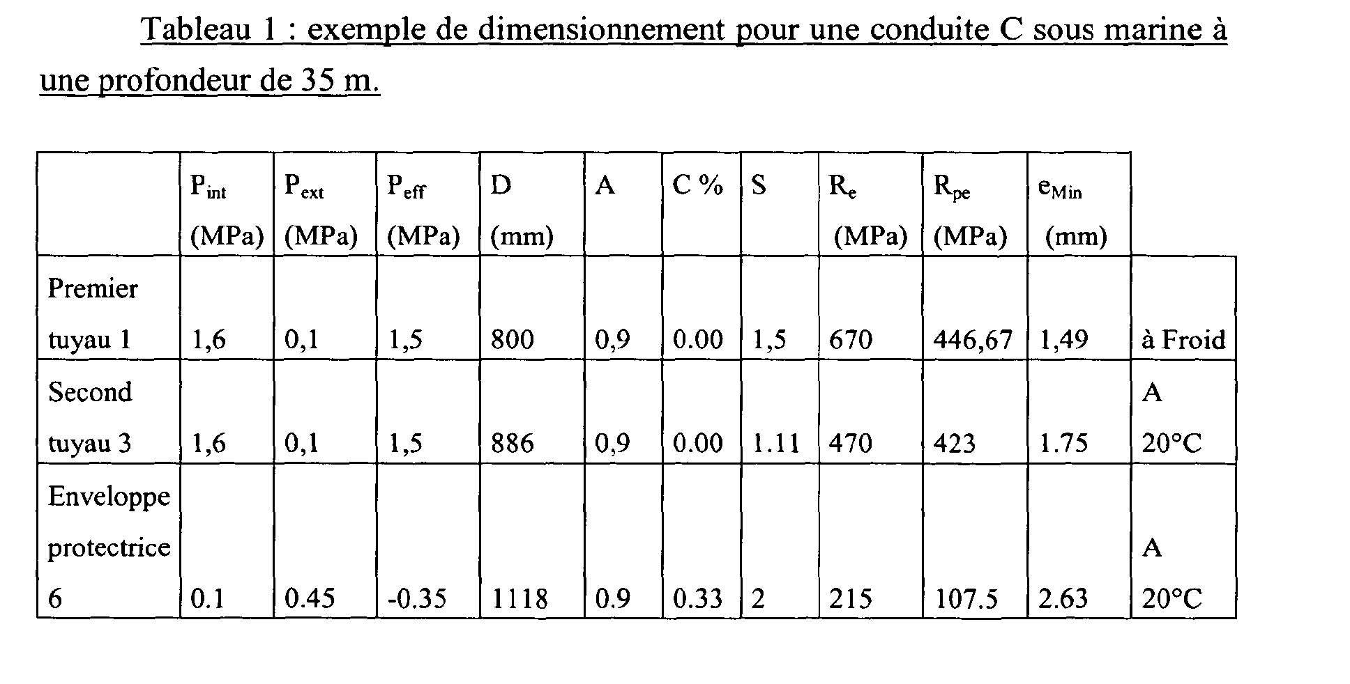
Claims (21)
ou granulaire comporte au moins un tronçon obturé à ses deux extrémités longitudinales par des dispositifs d'obstruction (8) en matériau isolant.Pipe according to claim 13, characterized in that said thermal insulation layer (2, 4) in powder form
or granular comprises at least one section closed at its two longitudinal ends by obstruction devices (8) of insulating material.
Priority Applications (1)
| Application Number | Priority Date | Filing Date | Title |
|---|---|---|---|
| CY20081100548T CY1107968T1 (en) | 2004-01-20 | 2008-05-26 | THERMAL INSULATED conductor |
Applications Claiming Priority (2)
| Application Number | Priority Date | Filing Date | Title |
|---|---|---|---|
| FR0400509A FR2865262B1 (en) | 2004-01-20 | 2004-01-20 | THERMALLY INSULATED DRIVING |
| FR0400509 | 2004-01-20 |
Publications (2)
| Publication Number | Publication Date |
|---|---|
| EP1557602A1 true EP1557602A1 (en) | 2005-07-27 |
| EP1557602B1 EP1557602B1 (en) | 2008-03-26 |
Family
ID=34630652
Family Applications (1)
| Application Number | Title | Priority Date | Filing Date |
|---|---|---|---|
| EP04293045A Active EP1557602B1 (en) | 2004-01-20 | 2004-12-20 | Thermical insulated conduit |
Country Status (17)
| Country | Link |
|---|---|
| US (1) | US20050155663A1 (en) |
| EP (1) | EP1557602B1 (en) |
| JP (1) | JP2005207592A (en) |
| KR (1) | KR100650827B1 (en) |
| CN (1) | CN100567788C (en) |
| AT (1) | ATE390601T1 (en) |
| AU (1) | AU2005200038B2 (en) |
| CA (1) | CA2491675C (en) |
| CY (1) | CY1107968T1 (en) |
| DE (1) | DE602004012701D1 (en) |
| EG (1) | EG23700A (en) |
| ES (1) | ES2304591T3 (en) |
| FR (1) | FR2865262B1 (en) |
| MX (1) | MXPA05000509A (en) |
| MY (1) | MY138600A (en) |
| PT (1) | PT1557602E (en) |
| TW (1) | TWI279503B (en) |
Cited By (2)
| Publication number | Priority date | Publication date | Assignee | Title |
|---|---|---|---|---|
| CN103557404A (en) * | 2013-11-06 | 2014-02-05 | 北京豪特耐管道设备有限公司 | Production method of heat insulation pipeline and heat insulation pipeline adopting method |
| CN104121431A (en) * | 2014-04-03 | 2014-10-29 | 刘兴仁 | Abrasion-resistant and corrosion-resistant lining heat insulation oil tube |
Families Citing this family (51)
| Publication number | Priority date | Publication date | Assignee | Title |
|---|---|---|---|---|
| FR2858841B1 (en) * | 2003-08-14 | 2007-02-09 | Technip France | METHOD OF DRAINING AND EXHAUSTING GAS FROM PERMEATION OF A FLEXIBLE TUBULAR DRIVE AND CONDUCT SUITABLE FOR ITS IMPLEMENTATION |
| US20060207673A1 (en) * | 2005-03-18 | 2006-09-21 | O'brien John V | Vacuum insulated assured flow piping |
| US8505857B2 (en) | 2006-08-18 | 2013-08-13 | Kellogg Brown & Root Llc | Systems and methods for supporting a pipe |
| US7997541B2 (en) * | 2006-08-18 | 2011-08-16 | Kellogg Brown & Root Llc | Systems and methods for supporting a pipe |
| KR100948578B1 (en) * | 2006-12-12 | 2010-03-18 | 한국생산기술연구원 | Insulator pipe having aerogel adiabatic sheet |
| US8127801B2 (en) * | 2007-04-29 | 2012-03-06 | Brower David V | Advance instrumentation methods for pipes and conduits transporting cryogenic materials |
| US7794805B2 (en) * | 2007-06-29 | 2010-09-14 | Schlumberger Technology Corporation | Thermal insulation barriers |
| RU2365889C1 (en) * | 2007-12-29 | 2009-08-27 | Шлюмберже Текнолоджи Б.В. | Method for detection of gas leak point in underground pipeline (versions) |
| EP2095938B1 (en) | 2008-02-29 | 2015-04-22 | G+H Marine GmbH | Formaldehyde-free pipe insulation |
| JP5227635B2 (en) * | 2008-03-28 | 2013-07-03 | 古河電気工業株式会社 | Fluid leak detection system |
| JP5184177B2 (en) * | 2008-03-28 | 2013-04-17 | 古河電気工業株式会社 | Flexible tube for cryogenic fluid transport |
| US9267330B2 (en) * | 2008-08-20 | 2016-02-23 | Foro Energy, Inc. | Long distance high power optical laser fiber break detection and continuity monitoring systems and methods |
| DE102008056987A1 (en) * | 2008-11-12 | 2010-05-20 | Rwe Power Ag | insulating cartridge |
| WO2011079844A1 (en) * | 2009-12-31 | 2011-07-07 | Kirkegaard Kim Joergen Schultz | A cement-based material comprising a nano-aerogel insulating tape material |
| FR2964456B1 (en) * | 2010-09-08 | 2013-05-10 | Commissariat Energie Atomique | DEVICE FOR DETECTING LEAKAGE AND COATING OF TRANSPORTATION MEMBER OR STORAGE OF FLUID COMPRISING SAID DETECTION DEVICE |
| KR101182204B1 (en) * | 2010-10-08 | 2012-09-14 | (주)나우이엔씨 | Explosion Proof In-line Heater |
| PT2472165E (en) * | 2010-12-30 | 2014-08-29 | Shell Int Research | Cryogenic fluid transfer tunnel assembly and method |
| EP2661578B1 (en) * | 2011-01-06 | 2019-07-31 | National Oilwell Varco Denmark I/S | An unbonded flexible pipe |
| CA2829288A1 (en) | 2011-01-25 | 2012-08-02 | Rns Technologies Bv | Insulation composition and method to detect water in an insulation composition |
| US9976687B2 (en) | 2012-05-18 | 2018-05-22 | Saprex, Llc | Breathable multi-component exhaust insulation system |
| US9388515B2 (en) | 2012-09-28 | 2016-07-12 | Saprex, Llc | Heat curable composite textile |
| FR2997747B1 (en) * | 2012-11-08 | 2015-01-16 | Technip France | FLEXIBLE CONDUIT FOR TRANSPORTING A CRYOGENIC FLUID, ASSOCIATED INSTALLATION AND METHOD |
| US9523512B2 (en) * | 2013-09-27 | 2016-12-20 | Flexible Technologies, Inc. | Insulated duct with air jacket and method of use |
| CN103591412A (en) * | 2013-10-30 | 2014-02-19 | 惠生(南通)重工有限公司 | Heat insulating ultra-low-temperature tube |
| CN103557405B (en) * | 2013-11-06 | 2015-10-14 | 北京豪特耐管道设备有限公司 | With prefabricated thermal isolated pipe production technology and the sash weight thereof of leakage monitoring system |
| WO2015066815A1 (en) * | 2013-11-08 | 2015-05-14 | Shawcor Ltd. | Thermally insulated tubular |
| FR3013816A1 (en) * | 2013-11-26 | 2015-05-29 | Air Liquide | SUPPORT ELEMENT, CRYOGENIC FLUID CIRCUIT AND CORRESPONDING METHOD |
| US10160655B2 (en) | 2014-05-15 | 2018-12-25 | Tahoe Technologies, Ltd. | Apparatus and method for manufacturing and packaging of high performance thermal insulator aerogels |
| FR3021385B1 (en) * | 2014-05-23 | 2017-01-20 | Itp Sa | TRUNK FOR A DUAL ENVELOPE CONDUIT MOUNTED THERMALLY ISOLATED AND HEATED THRUST AND METHOD FOR ITS IMPLEMENTATION |
| CA2960009C (en) * | 2014-10-23 | 2019-10-29 | Halliburton Energy Services, Inc. | Sealed downhole equipment and method for fabricating the equipment |
| CN104373755B (en) * | 2014-10-27 | 2016-08-17 | 宁夏天纵泓光余热发电技术有限公司 | Mineral heating furnace flue vacuum pouring material insulating tube |
| GB2545378B (en) * | 2014-11-25 | 2020-12-09 | Halliburton Energy Services Inc | Smart subsea pipeline with channels |
| GB2553681B (en) | 2015-01-07 | 2019-06-26 | Homeserve Plc | Flow detection device |
| GB201501935D0 (en) | 2015-02-05 | 2015-03-25 | Tooms Moore Consulting Ltd And Trow Consulting Ltd | Water flow analysis |
| EP3371508A4 (en) * | 2015-11-02 | 2019-06-19 | Flexsteel Pipeline Technologies, Inc. | Real time integrity monitoring of on-shore pipes |
| CN105485432B (en) * | 2016-01-28 | 2017-08-29 | 沈圣良 | A kind of high-temperature pipe fixed support and high-temperature pipe fixing means |
| USD800591S1 (en) | 2016-03-31 | 2017-10-24 | Homeserve Plc | Flowmeter |
| JP6802901B2 (en) * | 2016-04-15 | 2020-12-23 | サプレックス,リミテッド・ライアビリティ・カンパニー | Composite insulation system |
| WO2018094339A1 (en) | 2016-11-18 | 2018-05-24 | Saprex, Llc | Composite insulation system |
| CN106704768A (en) * | 2017-01-24 | 2017-05-24 | 高新伟 | Protective method for public fuel gas pipeline above ground |
| US10677260B2 (en) * | 2017-02-21 | 2020-06-09 | General Electric Company | Turbine engine and method of manufacturing |
| RU182117U1 (en) * | 2018-02-27 | 2018-08-03 | Общество С Ограниченной Ответственностью "Бт Свап" | DEVICE FOR COMPENSATION OF STRESSES AND PROTECTION OF JOINTS OF PIPELINES WITH CONCRETE COVERING FROM LOADS AND INFLUENCES |
| KR102112197B1 (en) * | 2019-10-08 | 2020-05-19 | (주)동인엔지니어링 | Low temperature pipe insulation apparatus |
| RU2754833C1 (en) * | 2020-08-04 | 2021-09-07 | Акционерное Общество "Российский Концерн По Производству Электрической И Тепловой Энергии На Атомных Станциях" (Ао "Концерн Росэнергоатом") | Reflective block thermal insulation for pipelines and / or equipment of reactor plants |
| CN112128494B (en) * | 2020-08-24 | 2023-12-01 | 上海齐耀动力技术有限公司 | Flange joint for vacuum interlayer pipeline and vacuum interlayer pipeline assembly |
| CN112318946B (en) * | 2020-10-30 | 2023-05-02 | 张家口宣化建投供热有限责任公司 | Heat preservation device for heating power resource conveying pipeline |
| CN112319705B (en) * | 2020-11-13 | 2022-05-10 | 上海海威斯特保温工程有限公司 | C-shaped LNG liquid cargo tank spraying type heat insulation system and construction method thereof |
| CN113983241A (en) * | 2021-11-10 | 2022-01-28 | 上海外高桥造船有限公司 | Method of installing reinforced pipe using structural retainer and reinforced pipe assembly |
| CN114033922A (en) * | 2021-11-18 | 2022-02-11 | 青海省水文地质工程地质环境地质调查院 | Preparation method of heat-insulating combined material suitable for hot dry rock single-hole heat-taking steam-discharging device |
| NO347314B1 (en) * | 2021-12-08 | 2023-09-11 | Nitrogas As | Method and a system for reducing corrosive environment for a pipeline |
| CN114576468A (en) * | 2022-01-25 | 2022-06-03 | 华能澜沧江水电股份有限公司 | Diversion type penstock protection device |
Citations (5)
| Publication number | Priority date | Publication date | Assignee | Title |
|---|---|---|---|---|
| US2611567A (en) * | 1946-03-18 | 1952-09-23 | Alexander H Isenberg | Insulated pipe anchor |
| US3388724A (en) * | 1965-04-05 | 1968-06-18 | Exxon Research Engineering Co | Submarine insulated lng pipeline |
| US4014369A (en) * | 1975-12-31 | 1977-03-29 | Exxon Research And Engineering Company | Triple pipe low temperature pipeline |
| EP0123186A1 (en) * | 1983-04-22 | 1984-10-31 | Fried. Krupp Gesellschaft mit beschränkter Haftung | Pressure-proof body with low thermal conductivity and high strength |
| FR2748545A1 (en) | 1996-05-09 | 1997-11-14 | Total Sa | Thermal isolated conduit for transfer of liquid natural gas |
Family Cites Families (10)
| Publication number | Priority date | Publication date | Assignee | Title |
|---|---|---|---|---|
| US2923650A (en) * | 1955-03-30 | 1960-02-02 | Seme Jean | Method of and device for heat-insulating piping for the long-distance conveyance of heating fluids |
| FR2301761A1 (en) * | 1975-02-24 | 1976-09-17 | Technigaz | CONDUCT FOR THE TRANSPORT OF A FLUID WHOSE TEMPERATURE IS DIFFERENT FROM THE AMBIENT TEMPERATURE |
| USH594H (en) * | 1985-04-12 | 1989-03-07 | Exxon Production Research Company | Jacketed pipeline system with pressurized gas to resist external stress |
| US4718459A (en) * | 1986-02-13 | 1988-01-12 | Exxon Production Research Company | Underwater cryogenic pipeline system |
| US5795102A (en) * | 1992-08-12 | 1998-08-18 | Corbishley; Terrence Jeffrey | Marine and submarine apparatus |
| US5390961A (en) * | 1993-04-28 | 1995-02-21 | Thermon Manufacturing Company | Dual wall thermally insulated conduit including skin effect heat tracing pipes |
| FR2746891B1 (en) | 1996-03-29 | 1998-06-05 | Itp | PIPE FOR DUAL THERMAL INSULATING PIPE TYPE PIPES |
| US6527015B2 (en) * | 1999-07-02 | 2003-03-04 | F. Glenn Lively | Insulated pipe |
| US7137651B2 (en) * | 2003-04-02 | 2006-11-21 | Chart Industries, Inc. | Fluid piping systems and pipe spools suitable for sub sea use |
| KR101156311B1 (en) * | 2003-05-06 | 2012-06-13 | 아스펜 에어로겔, 인코포레이티드 | Thermally insulating pipe and methods for the same |
-
2004
- 2004-01-20 FR FR0400509A patent/FR2865262B1/en not_active Expired - Fee Related
- 2004-12-20 ES ES04293045T patent/ES2304591T3/en active Active
- 2004-12-20 EP EP04293045A patent/EP1557602B1/en active Active
- 2004-12-20 PT PT04293045T patent/PT1557602E/en unknown
- 2004-12-20 AT AT04293045T patent/ATE390601T1/en not_active IP Right Cessation
- 2004-12-20 DE DE602004012701T patent/DE602004012701D1/en active Active
- 2004-12-30 CA CA002491675A patent/CA2491675C/en active Active
-
2005
- 2005-01-05 US US11/028,681 patent/US20050155663A1/en not_active Abandoned
- 2005-01-06 AU AU2005200038A patent/AU2005200038B2/en not_active Ceased
- 2005-01-11 TW TW094100756A patent/TWI279503B/en not_active IP Right Cessation
- 2005-01-11 MX MXPA05000509A patent/MXPA05000509A/en active IP Right Grant
- 2005-01-17 EG EG2005010028A patent/EG23700A/en active
- 2005-01-18 MY MYPI20050193A patent/MY138600A/en unknown
- 2005-01-19 CN CNB2005100055768A patent/CN100567788C/en not_active Expired - Fee Related
- 2005-01-19 JP JP2005012157A patent/JP2005207592A/en active Pending
- 2005-01-20 KR KR1020050005253A patent/KR100650827B1/en active IP Right Grant
-
2008
- 2008-05-26 CY CY20081100548T patent/CY1107968T1/en unknown
Patent Citations (5)
| Publication number | Priority date | Publication date | Assignee | Title |
|---|---|---|---|---|
| US2611567A (en) * | 1946-03-18 | 1952-09-23 | Alexander H Isenberg | Insulated pipe anchor |
| US3388724A (en) * | 1965-04-05 | 1968-06-18 | Exxon Research Engineering Co | Submarine insulated lng pipeline |
| US4014369A (en) * | 1975-12-31 | 1977-03-29 | Exxon Research And Engineering Company | Triple pipe low temperature pipeline |
| EP0123186A1 (en) * | 1983-04-22 | 1984-10-31 | Fried. Krupp Gesellschaft mit beschränkter Haftung | Pressure-proof body with low thermal conductivity and high strength |
| FR2748545A1 (en) | 1996-05-09 | 1997-11-14 | Total Sa | Thermal isolated conduit for transfer of liquid natural gas |
Cited By (3)
| Publication number | Priority date | Publication date | Assignee | Title |
|---|---|---|---|---|
| CN103557404A (en) * | 2013-11-06 | 2014-02-05 | 北京豪特耐管道设备有限公司 | Production method of heat insulation pipeline and heat insulation pipeline adopting method |
| CN103557404B (en) * | 2013-11-06 | 2015-11-25 | 北京豪特耐管道设备有限公司 | The insulated piping that a kind of production method of insulated piping and employing the method are produced |
| CN104121431A (en) * | 2014-04-03 | 2014-10-29 | 刘兴仁 | Abrasion-resistant and corrosion-resistant lining heat insulation oil tube |
Also Published As
| Publication number | Publication date |
|---|---|
| CY1107968T1 (en) | 2013-09-04 |
| EP1557602B1 (en) | 2008-03-26 |
| FR2865262B1 (en) | 2006-11-24 |
| CA2491675C (en) | 2008-03-11 |
| EG23700A (en) | 2007-05-22 |
| KR20050076684A (en) | 2005-07-26 |
| AU2005200038A1 (en) | 2005-08-04 |
| CA2491675A1 (en) | 2005-07-20 |
| TW200526894A (en) | 2005-08-16 |
| TWI279503B (en) | 2007-04-21 |
| ATE390601T1 (en) | 2008-04-15 |
| JP2005207592A (en) | 2005-08-04 |
| AU2005200038B2 (en) | 2009-05-28 |
| MY138600A (en) | 2009-07-31 |
| ES2304591T3 (en) | 2008-10-16 |
| PT1557602E (en) | 2008-06-16 |
| FR2865262A1 (en) | 2005-07-22 |
| MXPA05000509A (en) | 2005-11-17 |
| DE602004012701D1 (en) | 2008-05-08 |
| US20050155663A1 (en) | 2005-07-21 |
| CN100567788C (en) | 2009-12-09 |
| KR100650827B1 (en) | 2006-11-27 |
| CN1644972A (en) | 2005-07-27 |
Similar Documents
| Publication | Publication Date | Title |
|---|---|---|
| CA2491675C (en) | Thermally isolated conduit | |
| EP1828656B1 (en) | Light reinforced element of coaxial underwater pipes | |
| EP3317578B1 (en) | Securing a pipe in a housing | |
| EP2606269B1 (en) | End fitting for connecting a flexible pipe for transporting a cryogenic fluid | |
| EP1562823B1 (en) | Liquefied gas transfer installation and use thereof | |
| EP1058800A1 (en) | Heat insulating device and method for insulating at least a submarine pipeline at great depth | |
| FR2475185A1 (en) | FLEXIBLE CALORIFYING PIPE FOR PARTICULARLY CRYOGENIC FLUIDS | |
| WO2013093261A1 (en) | Vessel wall comprising a pipe | |
| EP1366320B1 (en) | Thermal insulation device for at least one underwater pipe comprising sealed partitions | |
| EP0031779A2 (en) | Pipeline for conveying warm or cold fluids | |
| FR2721681A1 (en) | Process for constructing oil pipes and pipe produced | |
| EP1070907A1 (en) | Method of making a thermally insulated pipe having an outer protection layer and pipe made by such method | |
| FR2951801A1 (en) | SUBMARINE CONDUCT APPLIED TO THE EXPLOITATION OF THERMAL ENERGY OF THE SEAS | |
| WO2021254999A1 (en) | Liquid dome of a storage tank for liquefied gas | |
| WO2021255000A1 (en) | Liquid dome of a storage tank for liquefied gas | |
| FR3078135A1 (en) | STORAGE AND TRANSPORTATION INSTALLATION OF A CRYOGENIC FLUID EMBEDDED ON A SHIP | |
| FR3135126A1 (en) | Tank wall crossed by a sealed fluid evacuation pipe | |
| WO2020089549A1 (en) | Storage facility for liquefied gas | |
| FR2636769A1 (en) | Structure of liquid metal-cooled nuclear reactor of the type with loops, with mounted vessel | |
| FR2862741A1 (en) | Insulated pipeline for transporting cryogenic liquid, has middle pipe of sufficient length such that during assembly, in cooperation with the linking parts, it prevents formation of a thermal bridge between the inner and outer pipes |
Legal Events
| Date | Code | Title | Description |
|---|---|---|---|
| PUAI | Public reference made under article 153(3) epc to a published international application that has entered the european phase |
Free format text: ORIGINAL CODE: 0009012 |
|
| AK | Designated contracting states |
Kind code of ref document: A1 Designated state(s): AT BE BG CH CY CZ DE DK EE ES FI FR GB GR HU IE IS IT LI LT LU MC NL PL PT RO SE SI SK TR |
|
| AX | Request for extension of the european patent |
Extension state: AL BA HR LV MK YU |
|
| 17P | Request for examination filed |
Effective date: 20050917 |
|
| AKX | Designation fees paid |
Designated state(s): AT BE BG CH CY CZ DE DK EE ES FI FR GB GR HU IE IS IT LI LT LU MC NL PL PT RO SE SI SK TR |
|
| GRAP | Despatch of communication of intention to grant a patent |
Free format text: ORIGINAL CODE: EPIDOSNIGR1 |
|
| GRAS | Grant fee paid |
Free format text: ORIGINAL CODE: EPIDOSNIGR3 |
|
| GRAA | (expected) grant |
Free format text: ORIGINAL CODE: 0009210 |
|
| AK | Designated contracting states |
Kind code of ref document: B1 Designated state(s): AT BE BG CH CY CZ DE DK EE ES FI FR GB GR HU IE IS IT LI LT LU MC NL PL PT RO SE SI SK TR |
|
| REG | Reference to a national code |
Ref country code: GB Ref legal event code: FG4D Free format text: NOT ENGLISH |
|
| REG | Reference to a national code |
Ref country code: CH Ref legal event code: EP Ref country code: IE Ref legal event code: FG4D Free format text: LANGUAGE OF EP DOCUMENT: FRENCH |
|
| REF | Corresponds to: |
Ref document number: 602004012701 Country of ref document: DE Date of ref document: 20080508 Kind code of ref document: P |
|
| GBT | Gb: translation of ep patent filed (gb section 77(6)(a)/1977) |
Effective date: 20080421 |
|
| REG | Reference to a national code |
Ref country code: PT Ref legal event code: SC4A Free format text: AVAILABILITY OF NATIONAL TRANSLATION Effective date: 20080530 |
|
| REG | Reference to a national code |
Ref country code: GR Ref legal event code: EP Ref document number: 20080401149 Country of ref document: GR |
|
| PG25 | Lapsed in a contracting state [announced via postgrant information from national office to epo] |
Ref country code: FI Free format text: LAPSE BECAUSE OF FAILURE TO SUBMIT A TRANSLATION OF THE DESCRIPTION OR TO PAY THE FEE WITHIN THE PRESCRIBED TIME-LIMIT Effective date: 20080326 |
|
| PG25 | Lapsed in a contracting state [announced via postgrant information from national office to epo] |
Ref country code: AT Free format text: LAPSE BECAUSE OF FAILURE TO SUBMIT A TRANSLATION OF THE DESCRIPTION OR TO PAY THE FEE WITHIN THE PRESCRIBED TIME-LIMIT Effective date: 20080326 |
|
| NLV1 | Nl: lapsed or annulled due to failure to fulfill the requirements of art. 29p and 29m of the patents act | ||
| PG25 | Lapsed in a contracting state [announced via postgrant information from national office to epo] |
Ref country code: PL Free format text: LAPSE BECAUSE OF FAILURE TO SUBMIT A TRANSLATION OF THE DESCRIPTION OR TO PAY THE FEE WITHIN THE PRESCRIBED TIME-LIMIT Effective date: 20080326 Ref country code: SI Free format text: LAPSE BECAUSE OF FAILURE TO SUBMIT A TRANSLATION OF THE DESCRIPTION OR TO PAY THE FEE WITHIN THE PRESCRIBED TIME-LIMIT Effective date: 20080326 |
|
| REG | Reference to a national code |
Ref country code: ES Ref legal event code: FG2A Ref document number: 2304591 Country of ref document: ES Kind code of ref document: T3 |
|
| REG | Reference to a national code |
Ref country code: IE Ref legal event code: FD4D |
|
| PG25 | Lapsed in a contracting state [announced via postgrant information from national office to epo] |
Ref country code: SE Free format text: LAPSE BECAUSE OF FAILURE TO SUBMIT A TRANSLATION OF THE DESCRIPTION OR TO PAY THE FEE WITHIN THE PRESCRIBED TIME-LIMIT Effective date: 20080626 Ref country code: SK Free format text: LAPSE BECAUSE OF FAILURE TO SUBMIT A TRANSLATION OF THE DESCRIPTION OR TO PAY THE FEE WITHIN THE PRESCRIBED TIME-LIMIT Effective date: 20080326 Ref country code: CZ Free format text: LAPSE BECAUSE OF FAILURE TO SUBMIT A TRANSLATION OF THE DESCRIPTION OR TO PAY THE FEE WITHIN THE PRESCRIBED TIME-LIMIT Effective date: 20080326 |
|
| PG25 | Lapsed in a contracting state [announced via postgrant information from national office to epo] |
Ref country code: RO Free format text: LAPSE BECAUSE OF FAILURE TO SUBMIT A TRANSLATION OF THE DESCRIPTION OR TO PAY THE FEE WITHIN THE PRESCRIBED TIME-LIMIT Effective date: 20080326 Ref country code: NL Free format text: LAPSE BECAUSE OF FAILURE TO SUBMIT A TRANSLATION OF THE DESCRIPTION OR TO PAY THE FEE WITHIN THE PRESCRIBED TIME-LIMIT Effective date: 20080326 |
|
| PG25 | Lapsed in a contracting state [announced via postgrant information from national office to epo] |
Ref country code: IS Free format text: LAPSE BECAUSE OF FAILURE TO SUBMIT A TRANSLATION OF THE DESCRIPTION OR TO PAY THE FEE WITHIN THE PRESCRIBED TIME-LIMIT Effective date: 20080726 |
|
| PG25 | Lapsed in a contracting state [announced via postgrant information from national office to epo] |
Ref country code: IE Free format text: LAPSE BECAUSE OF FAILURE TO SUBMIT A TRANSLATION OF THE DESCRIPTION OR TO PAY THE FEE WITHIN THE PRESCRIBED TIME-LIMIT Effective date: 20080326 Ref country code: DK Free format text: LAPSE BECAUSE OF FAILURE TO SUBMIT A TRANSLATION OF THE DESCRIPTION OR TO PAY THE FEE WITHIN THE PRESCRIBED TIME-LIMIT Effective date: 20080326 Ref country code: LT Free format text: LAPSE BECAUSE OF FAILURE TO SUBMIT A TRANSLATION OF THE DESCRIPTION OR TO PAY THE FEE WITHIN THE PRESCRIBED TIME-LIMIT Effective date: 20080326 Ref country code: DE Free format text: LAPSE BECAUSE OF FAILURE TO SUBMIT A TRANSLATION OF THE DESCRIPTION OR TO PAY THE FEE WITHIN THE PRESCRIBED TIME-LIMIT Effective date: 20080627 |
|
| PLBE | No opposition filed within time limit |
Free format text: ORIGINAL CODE: 0009261 |
|
| STAA | Information on the status of an ep patent application or granted ep patent |
Free format text: STATUS: NO OPPOSITION FILED WITHIN TIME LIMIT |
|
| 26N | No opposition filed |
Effective date: 20081230 |
|
| PG25 | Lapsed in a contracting state [announced via postgrant information from national office to epo] |
Ref country code: EE Free format text: LAPSE BECAUSE OF FAILURE TO SUBMIT A TRANSLATION OF THE DESCRIPTION OR TO PAY THE FEE WITHIN THE PRESCRIBED TIME-LIMIT Effective date: 20080326 Ref country code: BG Free format text: LAPSE BECAUSE OF FAILURE TO SUBMIT A TRANSLATION OF THE DESCRIPTION OR TO PAY THE FEE WITHIN THE PRESCRIBED TIME-LIMIT Effective date: 20080626 |
|
| PG25 | Lapsed in a contracting state [announced via postgrant information from national office to epo] |
Ref country code: MC Free format text: LAPSE BECAUSE OF NON-PAYMENT OF DUE FEES Effective date: 20081231 |
|
| REG | Reference to a national code |
Ref country code: CH Ref legal event code: PL |
|
| PG25 | Lapsed in a contracting state [announced via postgrant information from national office to epo] |
Ref country code: CY Free format text: LAPSE BECAUSE OF FAILURE TO SUBMIT A TRANSLATION OF THE DESCRIPTION OR TO PAY THE FEE WITHIN THE PRESCRIBED TIME-LIMIT Effective date: 20080326 |
|
| PG25 | Lapsed in a contracting state [announced via postgrant information from national office to epo] |
Ref country code: CH Free format text: LAPSE BECAUSE OF NON-PAYMENT OF DUE FEES Effective date: 20081231 Ref country code: LI Free format text: LAPSE BECAUSE OF NON-PAYMENT OF DUE FEES Effective date: 20081231 |
|
| PG25 | Lapsed in a contracting state [announced via postgrant information from national office to epo] |
Ref country code: HU Free format text: LAPSE BECAUSE OF FAILURE TO SUBMIT A TRANSLATION OF THE DESCRIPTION OR TO PAY THE FEE WITHIN THE PRESCRIBED TIME-LIMIT Effective date: 20080927 Ref country code: LU Free format text: LAPSE BECAUSE OF NON-PAYMENT OF DUE FEES Effective date: 20081220 |
|
| REG | Reference to a national code |
Ref country code: FR Ref legal event code: CJ Effective date: 20151022 |
|
| REG | Reference to a national code |
Ref country code: FR Ref legal event code: PLFP Year of fee payment: 12 |
|
| REG | Reference to a national code |
Ref country code: FR Ref legal event code: PLFP Year of fee payment: 13 |
|
| REG | Reference to a national code |
Ref country code: FR Ref legal event code: PLFP Year of fee payment: 14 |
|
| PGFP | Annual fee paid to national office [announced via postgrant information from national office to epo] |
Ref country code: TR Payment date: 20211206 Year of fee payment: 18 Ref country code: PT Payment date: 20211118 Year of fee payment: 18 Ref country code: GB Payment date: 20211220 Year of fee payment: 18 Ref country code: FR Payment date: 20211230 Year of fee payment: 18 |
|
| PGFP | Annual fee paid to national office [announced via postgrant information from national office to epo] |
Ref country code: IT Payment date: 20211213 Year of fee payment: 18 Ref country code: GR Payment date: 20211124 Year of fee payment: 18 Ref country code: BE Payment date: 20211221 Year of fee payment: 18 |
|
| PGFP | Annual fee paid to national office [announced via postgrant information from national office to epo] |
Ref country code: ES Payment date: 20220104 Year of fee payment: 18 Ref country code: CY Payment date: 20211122 Year of fee payment: 18 |
|
| PG25 | Lapsed in a contracting state [announced via postgrant information from national office to epo] |
Ref country code: PT Free format text: LAPSE BECAUSE OF NON-PAYMENT OF DUE FEES Effective date: 20230620 Ref country code: CY Free format text: LAPSE BECAUSE OF NON-PAYMENT OF DUE FEES Effective date: 20221220 |
|
| GBPC | Gb: european patent ceased through non-payment of renewal fee |
Effective date: 20221220 |
|
| REG | Reference to a national code |
Ref country code: BE Ref legal event code: MM Effective date: 20221231 |
|
| PG25 | Lapsed in a contracting state [announced via postgrant information from national office to epo] |
Ref country code: GB Free format text: LAPSE BECAUSE OF NON-PAYMENT OF DUE FEES Effective date: 20221220 |
|
| PG25 | Lapsed in a contracting state [announced via postgrant information from national office to epo] |
Ref country code: GR Free format text: LAPSE BECAUSE OF NON-PAYMENT OF DUE FEES Effective date: 20230705 Ref country code: FR Free format text: LAPSE BECAUSE OF NON-PAYMENT OF DUE FEES Effective date: 20221231 Ref country code: BE Free format text: LAPSE BECAUSE OF NON-PAYMENT OF DUE FEES Effective date: 20221231 |
|
| PG25 | Lapsed in a contracting state [announced via postgrant information from national office to epo] |
Ref country code: IT Free format text: LAPSE BECAUSE OF NON-PAYMENT OF DUE FEES Effective date: 20221220 |
|
| REG | Reference to a national code |
Ref country code: ES Ref legal event code: FD2A Effective date: 20240201 |