FIELD OF THE INVENTION
The present invention is related to a gasket material which is used for
an engine and a transmission for automotive and the like, especially, this gasket
material is manufactured from a joint seat, which is made from an ingredient
made by mixing and kneading rubber, reinforced fiber and filler, and pressurized
laminating and vulcanizing the ingredient by means of calender roll.
BACKGROUND OF THE INVENTION
Up to now, so-called asbestos joint seat was used as the material of
the gasket for the circumference of the engine carried on the vehicles and so on.
This asbestos joint seat was formed from following process; preparing a
ingredient M by mixing and kneading a asbestos as a reinforced fiber, nitrile
rubber and phenol resin; forming the joint seat by laminating and vulcanizing the
ingredient M on the hot roll HR of a calender roll which is comprising a pair of
rolls, that is, a hot roll HR and a cold roll CR as shown in Fig. 9.
However, recently, this asbestos joint seat is imposed regal controls
because of its influence of environment, so that the applicants of this application
are studying a joint seat which uses another fiber materials instead of asbestos,
and presents the result of such study as a paper "Development of non-asbestos
gasket material" which is contained in a proceedings of a lecture meeting
published by Society of Automotive Engineers of Japan, Inc. at May, 1992.
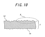
By the way, at a joint seat forming process, a laminated seat S
sticking on the hot roll HR always contacts to the cold roll CR with sliding, so
that, as shown in Fig. 10, a contact surface 1d of the laminated seat S, as a result
of a joint seat 1, opposed to the cold roll CR tends to coarse indicated as a portion
R compared with a contact surface 1e of the seat 1 opposed to the hot roll HR.
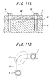
Therefore, as shown in Fig. 11A, when a gasket G which is made
from the joint seat 1 is used at a gasket insert portion between a transmission
housing H joined with a engine and a cover C connected to the housing H by
means of a plural of bolt B, a sealing efficiency of the gasket tends to decrease
because of the reducing of the surface pressure which is generated of the portion
like a corner portion CP which is offset to a straight line drawn between two
bolts B as shown in Fig. 11B, or a portion MP which lies between two bolts B
and has low rigidity of cover C as shown in Fig. 11A. In such a portion, if a
roughness of the contact surface of a sealing subject like the housing H and the
cover C which contacts the gasket G, a problem is generated that burying of
micro gap between the contact surface of the sealing subject like the housing H
and the cover C and gasket G becomes insufficient, so the sealing effect by the
gasket G becomes difficult. And the contact surface 1e of the joint seat 1
opposed to the hot roll HR becomes coarse to some extent caused from the ratio
of the reinforced fiber, but such roughness is less than that of the surface 1d
opposed to the cold roll CR.
So, to solve such problem of the decline of the sealing effect, the
applicant tried the following solutions to improve the sealing effect of the gasket;
However, these solutions has following problems respectively; in the
solution 1), the latex layer considerably swells when an automatic transmission
fluid (ATF) infiltrated into the layer, so if a gasket G made from a joint seat 1
with the latex layer 2 applied to the gasket insert portion between the transmission
housing H and the cover C, deterioration of the latex layer progresses
and leakage of ATF is generated by using this gasket in the long time under the
high temperature; in the solution 2), electrical erosion is generated in a gasket
insert portion by the gasket which depends on the material of the housing H or
the cover C or kind of the media to sealing, or the manufacturing cost will high
because the solid lubricant is expensive; and in the solution 3), sealing effect at
the area of the low surface pressure will drop adversely because of the decrease
of the essential compression effect of the joint seat.
As described above, the joint seat is generally manufactured from
forms a laminated seat on the hot roll of the calender roll by mixing and rolling
the ingredient attached on the hot roll, and breaks away the seat from the chilled
the hot roll afterward. Therefore, the ingredient of the joint seat requires the
characteristics that it is easy to attach the heated hot roll but difficult to the cold
roll, and easy to break away from the chilled hot roll after the forming of the seat.
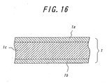
Therefore, up to now, the joint seat 1 generally composed as a three-layer
construction which comprises a front surface layer 1a which is composed as
so-called a dish component that is adhered on the hot roll, a back surface layer 1b
which is composed as so-called a finished component that is difficult to adhere
on the cold roll and, a middle layer 1c which is composed as so-called a middle
component which is intervened between the front surface layer and the back
surface layer and has a sufficient mechanical strength. There is generally used a
natural rubber as a rubber material which is used as the dish component.
However, the natural rubber has a characteristic that it has a large permanent
compression strain under the heat-suffering environment.
On the other hand, as shown in Figs. 11A and 11B, when the gasket is
used at a gasket insert portion between a transmission housing joined with a
engine and a cover connected to the housing by means of a plural of bolt B, for
example, a surface pressure acts upon the gasket is high directly below the bolt.
But the surface pressure is low at the corner portion, which is offset to a straight
line drawn between two bolts, or a bolt span portion, which lies between two
bolts. So it is well known the difference of the surface pressure is arise. Such
the difference of the surface pressure recently tends to increase as the rigidity of
the constructive body becomes low with the weight saving of the body. And the
low rigidity of the constructive body arises the change of the gap between the
seal because of the change of the temperature and the like; such the change
brings out the increase of the additional difference of the surface pressure.
Therefore, when the gasket which is formed from the above-mentioned
present joint seat 1 at the sealing portion of the structural body that is
composed from fastening used by a fastener such as bolt, the fastening force of
the bolt is determined under the condition to ensure the sealing effect at the low
surface pressure potion. So a high surface pressure acts upon the gasket directly
below of the bolt consequently, there exists the problem that the permanent
pressure strain of the front surface 1a which the above-mentioned natural rubber
used is facilitated and the stress relaxation increases, so the fastening torque of
the bolt decreases and it is possible to arise the leakage of the media for sealing.
DISCLOSURE OF THE INVENTION
The object of this invention is to provide the gasket material to be
solved the above-mentioned problems advantageously. The gasket material in
the first point of view of this invention that is manufactured from a joint seat
which is made from an ingredient made by mixing and kneading rubber,
reinforced fiber and filler, and pressurized laminating and vulcanizing the
ingredient by means of calender roll, is characterized in that at least the
outermost layer of the joint seat that faces the cold roll is formed to have its
flexibility and smoothness.
According to the gasket material of this invention, at least the cold
roll side of the outermost layer of the joint seat to make the gasket is formed to
have its flexibility and smoothness, so the burying of micro gap between the
contact surface of the sealing subject and the gasket can achieved sufficiently
under the low surface pressure, and can improve the seal efficiency of the gasket.
In the gasket material of this invention, the smoothness of the
outermost layer is preferably that the surface roughness Rz (average of 10 points)
is less or equal to 20µm. If this Rz is less or equal to 20µm, the seal efficiency
will be improved to a large extent as described afterward.
Additionally, the gasket material of this invention, the composition of
the outermost layer is preferably composed from that the rate of aramid fiber as
the reinforced fiber is under 7wt%, and the rate of rubber is 15wt% - 25wt%.
By this composition, the flexibility of the outermost layer can be acquired.
In this connection, the surface roughness becomes small as much as there are
many rates of the rubber again as much as there are a few rates of the aramid
fiber.
Furthermore, in the gasket material of this invention, it is desirable
that the thickness of the above outermost layer is 30µm - 150µm. If the layer
has such thickness, it can maintain the affection of the stress relaxation caused by
permanent compression strain is small with acquiring the flexibility of the layer.
Moreover, the gasket material in the second point of view of this
invention that is manufactured from a joint seat which is made from an ingredient
made by mixing and kneading rubber, reinforced fiber and filler, and pressurized
laminating and vulcanizing the ingredient by means of calender roll, is characterized
in that the joint seat has an mono-layer structure and, the fundamental
composition of the ingredient materials is that the rate of aramid fiber as the
reinforced fiber is over 15wt%, the rate of NBR as the rubber material is 10wt% -
30wt%, the rate of phenol resin as the filler is 2wt% - 26wt%, and the remainder
is the inorganic filler.
According to the gasket material of this invention, since the joint seat
that composes the gasket material has a mono-layer structure without surface
layer of the dish component which uses natural rubber that is a permanent
compression strain element at hot rolling process, the leakage of the media for
seal such as lubricant or working oil or the like caused from the decrease of the
fastening torque of the bolt due to the stress relaxation where the large difference
of the surface pressure is existed in the heat-subjected environment such as the
peripheral of the engine. Furthermore, the phenol resin as the filler with 2wt% -
26wt% gives the ingredients the moderate adherence for the running hot roll with
high temperature and the moderate ability of detachment, so it can be favorable
to form the joint seat by means of the calender roll.
Moreover, in the gasket material of this invention, the phenol resin is
preferably resol type. It is because this gives the good dispersion of the phenol
resin in the ingredient material.
BRIEF EXPLANATION OF THE DRAWING
Fig. 1 shows a cross sectional view of a joint seat as one embodiment
of the gasket material of this invention in above the first point of view.
Fig. 2 shows a enlarged cross sectional view of the gasket that is
formed from the above joint seat, and the gasket is under the condition that it was
inserted between a housing and a cover of a transmission.
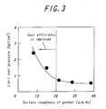
Fig. 3 shows a diagram of the relation of the roughness of the gasket
surface and the seal efficiency according to the gasket, which is formed from the
joint seat of above embodiment and to the gasket, which is formed from the
existing joint seat.
Fig. 4 shows a diagram of the seal efficiency under the low surface
pressure of the gasket, which is formed from the joint seat of above embodiment,
and of the gasket, which is formed from the existing joint seat.
Fig. 5 shows a diagram of the efficiency of fill the surface roughness
of flange with the gasket, which is formed from the joint seat of above
embodiment, and with the gasket, which is formed from the existing joint seat.
Fig. 6 shows a cross sectional view of a joint seat as one embodiment
of the gasket material of this invention in above the second point of view.
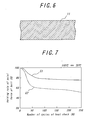
Fig. 7 shows a diagram of the relation of the cool and heat cycle and
the holding rate of the axial force of the bolt according to the gasket, which is
formed from the joint seat of above embodiment and to the gasket, which is
formed from the existing joint seat.
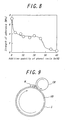
Fig. 8 shows a diagram of the relation of the additive quantity of
phenol resin to the ingredient and the strength of the attachment of the ingredient
to the hot roll according to the gasket, which is formed from the joint seat of
above embodiment, and to the gasket, which is formed from the existing joint
seat.
Fig. 9 shows a method of manufacturing of joint seat by calender roll.
Fig. 10 shows a cross sectional view of the condition of the surface of
the existing joint seat.
Fig. 11A and Fig. 11B shows a cross sectional view and a plan view
of the condition of the gasket which is inserted between a housing and a cover of
a transmission.
Fig. 12 shows an enlarged cross sectional view of the condition of the
gasket that is made from existing joint seat and that is inserted between a housing
and a cover of a transmission.
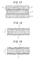
Fig. 13 shows a cross sectional view of the joint seat with a latex
layer as an outermost layer.
Fig. 14 shows a cross sectional view of the joint seat with a solid
lubricant coating on its surface.
Fig. 15 shows a method for the improvement of the surface
smoothness of the joint seat by heat pressing.
Fig. 16 shows a cross sectional view of the present joint seat.
THE BEST MODE FOR PRACTICING THE INVENTION
There will be described hereinafter an embodiment according the
present invention, with reference to the accompanying drawings.
Fig. 1 shows a cross sectional view of one embodiment of the gasket
material of this invention in above-mentioned the first point of view, the numeral
1 indicates a joint seat as the gasket material of this embodiment. This joint seat
1 has three-layer construction, that is, a front surface layer 1a and a back surface
layer 1b that these layers forms outermost layer respectively, and a middle layer
1c that exists between the front surface and back surface layer. In this embodiment,
these surface layer 1a and 1b is formed to have flexibility and smoothness.
In manufacturing this joint seat 1 of the embodiment, as shown in
Fig. 9, at first, a ingredient material M is made by mixing rubber such as NBR
(Nitrile-Butadiene-Rubber), aramid fiber as a reinforced fiber and inorganic filler
such as barium sulfate, then this ingredient material M feeds on a hot roll HR of
a calender roll which comprises a pair of rolls, namely, hot roll HR and cold roll
CR, forming a laminated ingredient on the hot roll HR by mixing and pressing
with the use of these rolls, furthermore forming a joint seat S by vulcanizing and
curing the ingredient with the use of the heat of the hot roll HR, hereinafter the
joint seat 1 forms by detaching the seat S from the hot roll HR. In this process,
the above-mentioned the front surface layer 1a, the back surface layer 1b and the
middle layer 1c of the three layers of the joint seat 1 are formed by mainly varying
the composing quantity of the reinforced fiber. As for the more detail of this
process, please refer the aforementioned paper "Development of non-asbestos
gasket material". In this connection, in page 179 of this paper, Fig. 5 shows an
examples of the composition of aramid fiber, glass fiber and NBR of the middle
layer, especially, in the percentage of composition that is indicated by point 5,
aramid fiber is about 24wt%, glass fiber is about 33wt% and NBR is about 43wt%.
In this embodiment, to make the front surface 1a flexibly and
smoothly, the composition of the front surface 1a is configured that the
percentage of aramid fiber is less and equal to 7wt% and rubber is 15wt% -
25wt%. And this front surface 1a is formed that its thickness is 30µm - 150µm.
In the joint seat 1 of this embodiment, the front surface layer 1a that
is outermost layer of the joint seat 1 which is the cold roll side (the side having a
contact surface that attaches to cold roll CR) is formed to be flexibly and
smoothly, so like a portion V that is shown in Fig. 2, burying of the micro gap
that exists between the cover C as the sealing subject and the gasket G can
achieve sufficiently under the low surface pressure, and consequently, the seal
efficiency of the gasket can be improved. Furthermore, the back surface layer
1b which is the hot roll side (the side having a contact surface that attaches to hot
roll HR) is also formed to be flexibly and smoothly, thus burying of the micro
gap that exists between the housing H and the gasket G can achieve sufficiently
under the low surface pressure, and consequently, the seal efficiency of the
gasket can be improved.
Fig. 3 shows a experimental result of the limit seal pressure of the
gasket which made from the joint seat 1 of this embodiment and of the gasket
which made from the present joint seat under the condition that a number of these
gasket with difference surface roughness made respectively, each gasket is held
between two metal flanges, and the surface roughness of the flange: 11.7µm
(Rmax, ▿▿), surface pressure of fastening of these flanges: 5MPa, sealing
media: air, test temperature: 20°C±5°C. As seen from this graph, the gasket that
is made from the joint seat 1 of this embodiment makes the seal efficiency
improve drastically.
Fig. 4 shows another experimental result of the limit seal pressure of
the gasket which made from the joint seat 1 of this embodiment with the surface
roughness 14.5µm (indicated by the curve G1 in the graph) and of the gasket as a
comparative example which made from the present joint seat with the surface
roughness 38.6µm (indicated by the curve G2 in the graph) under the condition
that each gasket is held between two metal flanges with the surface roughness of
the flange: 11.7µm (Rmax, ▿▿), sealing media: air, test temperature: 20°C±5°C.
It is also understood that the gasket that is made from the joint seat 1 of this
embodiment has less degree of decrease of seal efficiency under the low surface
pressure area as the surface pressure of fastening is less and equal to 6MPa, and
has the excellence of the seal efficiency at the low surface pressure area.
Moreover, Fig. 5 shows the other experimental result of the limit seal
pressure of the gasket which made from the joint seat 1 of this embodiment with
the surface roughness 14.5µm (indicated by the curve G1 in the graph) and of the
gasket as a comparative example which made from the present joint seat with the
surface roughness 38.6µm (indicated by the curve G2 in the graph) under the
condition that each gasket is held between two metal flanges with different
surface roughness each other, and surface pressure of fastening of these flanges:
6MPa, sealing media: air, test temperature: 20°C±5°C. It is understood that the
gasket that is made from the joint seat 1 of this embodiment has the excellence of
the seal efficiency on the rough surface of the sealing subject and has less degree
of the seal efficiency although the surface roughness of the flange become worse.
Example 1
The following Table 1 - Table 8 respectively shows the thickness and
surface roughness of 8 kinds of samples of the gasket that are formed from the
joint seat 1 of this invention, each joint seat is made by the combination which is
selected from the groups that the each of the groups is; the composition of the
aramid fiber is 3wt% or 6wt%; the composition of the NBR is 18wt% or 23wt%;
the thickness of the surface layer (
front surface layer 1a and back
surface layer
1b) is 140µm or 75µm (the thickness of one layer).
| Thickness of gasket | 0.496mm |
| Surface Roughness (Rz) | 17.2µm |
| Thickness of surface layer | 75µm |
| Composition of surface layer of gasket | Aramid fiber | 6% |
| NBR | 18% |
| Inorganic fiber | remainder |
| Thickness of gasket | 0.530mm |
| Surface Roughness (Rz) | 16.7µm |
| Thickness of surface layer | 140µm |
| Composition of surface layer of gasket | Aramid fiber | 6% |
| NBR | 18% |
| Inorganic fiber | remainder |
| Thickness of gasket | 0.497mm |
| Surface Roughness (Rz) | 16.2µm |
| Thickness of surface layer | 75µm |
| Composition of surface layer of gasket | Aramid fiber | 6% |
| NBR | 23% |
| Inorganic fiber | remainder |
| Thickness of gasket | 0.505mm |
| Surface Roughness (Rz) | 15.6µm |
| Thickness of surface layer | 140µm |
| Composition of surface layer of gasket | Aramid fiber | 6% |
| NBR | 23% |
| Inorganic fiber | remainder |
| Thickness of gasket | 0.499mm |
| Surface Roughness (Rz) | 12.7µm |
| Thickness of surface layer | 75µm |
| Composition of surface layer of gasket | Aramid fiber | 3% |
| NBR | 18% |
| Inorganic fiber | remainder |
| Thickness of gasket | 0.501mm |
| Surface Roughness (Rz) | 12.1µm |
| Thickness of surface layer | 140µm |
| Composition of surface layer of gasket | Aramid fiber | 3% |
| NBR | 18% |
| Inorganic fiber | remainder |
| Thickness of gasket | 0.498mm |
| Surface Roughness (Rz) | 12.0µm |
| Thickness of surface layer | 75µm |
| Composition of surface layer of gasket | Aramid fiber | 3% |
| NBR | 23% |
| Inorganic fiber | remainder |
| Thickness of gasket | 0.500mm |
| Surface Roughness (Rz) | 11.8µm |
| Thickness of surface layer | 140µm |
| Composition of surface layer of gasket | Aramid fiber | 3% |
| NBR | 23% |
| Inorganic fiber | remainder |
These samples 1 - 8 of the gasket have enough smooth surface that the
surface roughness is 17.2µm - 11.8µm, and it was turned out that these samples
also have good seal efficiency in the low surface pressure area that the limit seal
pressure is 2.7kgf/cm2 in all of these samples from the result of the test of the limit
seal pressure under the condition that each gasket sample is held between two
metal flanges, and the surface roughness of the flange: 23.5µm, surface pressure of
fastening of these flanges: 4MPa, sealing media: air, test temperature: 20°C±5°C.
In addition, this invention is not limited by the above-mentioned
embodiment, as the other embodiment, for example, the front surface layer 1a of
the joint seat 1 may be only formed to be flexibly and smoothly, and this joint
seat 1 may be formed to have double-layer structure. Furthermore, as a matter of
course, this gasket material of this invention can be used to the gasket except for
the gasket that is inserted between the housing H and cover C of a transmission.
Then, Fig. 6 shows a cross sectional view of another embodiment of
the gasket material of this invention in above-mentioned the second point of view,
the numeral 11 indicates a joint seat as the gasket material of this embodiment.
This joint seat 11 has monolayer construction compositionally.
In manufacturing the joint seat 11 of this embodiment, at first, a
ingredient material is made by mixing NBR as a rubber material, aramid fiber as
a reinforced fiber and phenol resin and the like as filler, then this ingredient
material feeds on a hot roll of a calender roll which comprises a pair of rolls,
namely, heated hot roll and chilled cold roll, forming a laminated ingredient on
the hot roll by mixing and pressing with the use of these rolls, furthermore
forming a laminated seat by vulcanizing and curing the ingredient with the use of
the heat of the hot roll, hereinafter the joint seat 11 formed by detaching the seat
from the hot roll. As for the more detail of this process, please refer the
aforementioned paper "Development of non-asbestos gasket material".
In this embodiment, to make the ingredient have a moderate adherence,
the composition of the ingredient is configured that the percentage of aramid
fiber is over 15wt% and NBR is 10wt% - 30wt%, phenol resin is more 2wt% -
26wt%, and the remains are inorganic fiber. And the phenol resin is the resol
type (for example, product name PR-217 of Sumitomo bakelite Co. Ltd., the
weight of the solid content is 100wt%).
Since the joint seat 11 of this embodiment has a mono-layer structure
without any surface layer of the dish component which is made from natural
rubber that has different composition from the middle component and is a
permanent compression strain element in the hot rolling process, according to the
joint seat 11 of this embodiment, the leakage of the sealing media such as a
lubricant or working oil or the like caused from the decrease of the fastening
torque of the bolt due to the stress relaxation where the large difference of the
surface pressure is existed in the heat-subjected environment such as the
peripheral of the engine. Furthermore, the phenol resin as the filler with 2wt% -
26wt% gives the ingredients the moderate adherence for the running hot roll with
high temperature and the moderate ability of detachment, so it is favorable to
form the joint seat by means of the calender roll.
Moreover, according to the joint seat 11 of this embodiment, the
phenol resin that is used as the ingredient is resol type, so it has a good
dispersibility in the ingredient, thus, the above-mentioned action and effect of
this invention can be brought perfectly.
Fig. 7 shows an experimental result of the retention of the axial force
of bolt of the gasket which made from the joint seat 11 of this embodiment
(indicated by the curve G1 in the graph) and of the gasket as a comparative
example which made from the present joint seat with three-layer structure
(indicated by the curve G2 in the graph) via the experiment of degradation by
thermal shock cycle under the condition that each gasket is held between two
metal flanges by a bolt, the surface pressure of fastening of these flanges :
150MPa, repeat the heating and cooling between 150°C and 20°C. It will be
understood that the gasket formed from the joint seat 11 of this embodiment has a
high retention of the axial force of bolt and a small stress relaxation by the
permanent compression strain.
Example 2
The following Table 9 shows the experimental result of the attach
efficiency of the ingredient in the making of the joint seat to the hot roll with a
high temperature, the samples 9 - 14 are formed from the
joint seat 11 of this
embodiment, each samples have different composition of aramid fiber, phenol
resin and NBR as the rubber material, and the comparative samples 1 - 3 are
formed from the joint seat that the composition of phenol resin of the seats are
0wt%, 35wt % and 40wt%, respectively, and these comparative samples thus are
out of the range of the embodiment of this invention. This experiment was
executed under the condition that the surface pressure: 100MPa, temperature:
100°C and period of time: 60min. And Fig. 8 shows the relation of the strength
of attachment and the composition of phenol resin of these samples.
| Examples of composition | Composition (wt%) | Performance of joint seat |
| | Aramid fiber | Phenol resin | rubber | Inorganic filler | strength of attachment (MPa) |
| Sample 9 | 20 | 3 | 20 | remainder | 4.2 |
| Sample 10 | 20 | 8 | 25 | remainder | 4.0 |
| Sample 11 | 20 | 10 | 24 | remainder | 3.5 |
| Sample 12 | 20 | 16 | 23 | remainder | 3.2 |
| Sample 13 | 15 | 20 | 27 | remainder | 3.7 |
| Sample 14 | 20 | 26 | 23 | remainder | 3.0 |
| Comparative sample 1 | 15 | 0 | 18 | remainder | 7.5 |
| Comparative sample 2 | 25 | 35 | 20 | remainder | 0.8 |
| Comparative sample 3 | 25 | 40 | 10 | remainder | 0.4 |
From these Table 9 and Fig. 8, it is understood that the ingredient has
a moderate strength of attachment when the additive quantity of phenol resin is
between 2wt% - 26wt%, and has too large strength of attachment when the
quantity is less than 2 wt%, thus it makes difficult to detach the laminated seat
from the hot roll, and too small strength of attachment when the quantity is over
26wt%, thus it makes difficult to laminate the ingredient on the hot roll.
Furthermore, with respect to the gaskets that is formed from the joint
seat 11 of the above samples, the tensile test was executed under the condition
which is defined in JIS K 6251, and buckling fatigue test was executed under the
condition that a ring-shaped sample was set between a pair of jigs and one of the
jigs was reciprocating slid at the distance of movement 300µm and frequency
1Hz by an actuator with loading a predetermined surface pressure by the
hydropress whether the fluff of the fiber generates or not at reciprocating cycle
3000cycle, and the buckling fatigue surface pressure is determined as the surface
pressure when the fluff of the sample is generated, and the limit seal pressure test
was executed under the condition that the nitrogen gas was supplied to inside the
sample which the fluff generated via the jigs and the soap solution was applied to
the periphery of the sample to check the leakage of the nitrogen gas, and the limit
seal pressure is measured as the gas pressure when the leakage is generated. As
a result of these test, these samples of this invention has a high tensile strength
over 25MPa, and holds a buckling fatigue surface pressure over 80MPa, and has
a limit seal pressure over 2.0kgf/cm2.
Moreover, this invention is not limited by the above-mentioned
embodiments, for example, the phenol resin may be non-resol type. And the
gasket material of this invention of course can be used as the gasket to the
periphery of engine instead of the gasket that is inserted between the housing and
the cover of the transmission.
POSSIBILITY OF APPLICATION IN INDUSTRY
According to the gasket material in the first point of view of this
invention, the burying of micro gap between the contact surface of the sealing
subject and the gasket can achieved sufficiently under the low surface pressure,
and can improve the seal efficiency of the gasket.
Moreover, according to the gasket material in the second point of
view of this invention, the leakage of the media for seal such as lubricant or
working oil or the like caused from the decrease of the fastening torque of the
bolt due to the stress relaxation where the large difference of the surface pressure
is existed in the heat-subjected environment such as the peripheral of the engine,
and it can be favorable to form the joint seat by means of the calender roll.