EP1557578A1 - Weatherproof low friction spindle unit - Google Patents
Weatherproof low friction spindle unit Download PDFInfo
- Publication number
- EP1557578A1 EP1557578A1 EP05100283A EP05100283A EP1557578A1 EP 1557578 A1 EP1557578 A1 EP 1557578A1 EP 05100283 A EP05100283 A EP 05100283A EP 05100283 A EP05100283 A EP 05100283A EP 1557578 A1 EP1557578 A1 EP 1557578A1
- Authority
- EP
- European Patent Office
- Prior art keywords
- shaft
- spindle unit
- bearing
- housing
- weatherproof
- Prior art date
- Legal status (The legal status is an assumption and is not a legal conclusion. Google has not performed a legal analysis and makes no representation as to the accuracy of the status listed.)
- Granted
Links
Images



Classifications
-
- F—MECHANICAL ENGINEERING; LIGHTING; HEATING; WEAPONS; BLASTING
- F16—ENGINEERING ELEMENTS AND UNITS; GENERAL MEASURES FOR PRODUCING AND MAINTAINING EFFECTIVE FUNCTIONING OF MACHINES OR INSTALLATIONS; THERMAL INSULATION IN GENERAL
- F16C—SHAFTS; FLEXIBLE SHAFTS; ELEMENTS OR CRANKSHAFT MECHANISMS; ROTARY BODIES OTHER THAN GEARING ELEMENTS; BEARINGS
- F16C19/00—Bearings with rolling contact, for exclusively rotary movement
- F16C19/02—Bearings with rolling contact, for exclusively rotary movement with bearing balls essentially of the same size in one or more circular rows
- F16C19/14—Bearings with rolling contact, for exclusively rotary movement with bearing balls essentially of the same size in one or more circular rows for both radial and axial load
- F16C19/18—Bearings with rolling contact, for exclusively rotary movement with bearing balls essentially of the same size in one or more circular rows for both radial and axial load with two or more rows of balls
-
- F—MECHANICAL ENGINEERING; LIGHTING; HEATING; WEAPONS; BLASTING
- F16—ENGINEERING ELEMENTS AND UNITS; GENERAL MEASURES FOR PRODUCING AND MAINTAINING EFFECTIVE FUNCTIONING OF MACHINES OR INSTALLATIONS; THERMAL INSULATION IN GENERAL
- F16C—SHAFTS; FLEXIBLE SHAFTS; ELEMENTS OR CRANKSHAFT MECHANISMS; ROTARY BODIES OTHER THAN GEARING ELEMENTS; BEARINGS
- F16C35/00—Rigid support of bearing units; Housings, e.g. caps, covers
- F16C35/08—Rigid support of bearing units; Housings, e.g. caps, covers for spindles
- F16C35/12—Rigid support of bearing units; Housings, e.g. caps, covers for spindles with ball or roller bearings
-
- A—HUMAN NECESSITIES
- A01—AGRICULTURE; FORESTRY; ANIMAL HUSBANDRY; HUNTING; TRAPPING; FISHING
- A01K—ANIMAL HUSBANDRY; AVICULTURE; APICULTURE; PISCICULTURE; FISHING; REARING OR BREEDING ANIMALS, NOT OTHERWISE PROVIDED FOR; NEW BREEDS OF ANIMALS
- A01K89/00—Reels
- A01K89/015—Reels with a rotary drum, i.e. with a rotating spool
-
- A—HUMAN NECESSITIES
- A01—AGRICULTURE; FORESTRY; ANIMAL HUSBANDRY; HUNTING; TRAPPING; FISHING
- A01K—ANIMAL HUSBANDRY; AVICULTURE; APICULTURE; PISCICULTURE; FISHING; REARING OR BREEDING ANIMALS, NOT OTHERWISE PROVIDED FOR; NEW BREEDS OF ANIMALS
- A01K89/00—Reels
- A01K89/015—Reels with a rotary drum, i.e. with a rotating spool
- A01K89/01931—Spool or spool shaft details
-
- F—MECHANICAL ENGINEERING; LIGHTING; HEATING; WEAPONS; BLASTING
- F16—ENGINEERING ELEMENTS AND UNITS; GENERAL MEASURES FOR PRODUCING AND MAINTAINING EFFECTIVE FUNCTIONING OF MACHINES OR INSTALLATIONS; THERMAL INSULATION IN GENERAL
- F16C—SHAFTS; FLEXIBLE SHAFTS; ELEMENTS OR CRANKSHAFT MECHANISMS; ROTARY BODIES OTHER THAN GEARING ELEMENTS; BEARINGS
- F16C35/00—Rigid support of bearing units; Housings, e.g. caps, covers
- F16C35/04—Rigid support of bearing units; Housings, e.g. caps, covers in the case of ball or roller bearings
-
- F—MECHANICAL ENGINEERING; LIGHTING; HEATING; WEAPONS; BLASTING
- F16—ENGINEERING ELEMENTS AND UNITS; GENERAL MEASURES FOR PRODUCING AND MAINTAINING EFFECTIVE FUNCTIONING OF MACHINES OR INSTALLATIONS; THERMAL INSULATION IN GENERAL
- F16C—SHAFTS; FLEXIBLE SHAFTS; ELEMENTS OR CRANKSHAFT MECHANISMS; ROTARY BODIES OTHER THAN GEARING ELEMENTS; BEARINGS
- F16C35/00—Rigid support of bearing units; Housings, e.g. caps, covers
- F16C35/04—Rigid support of bearing units; Housings, e.g. caps, covers in the case of ball or roller bearings
- F16C35/06—Mounting or dismounting of ball or roller bearings; Fixing them onto shaft or in housing
- F16C35/07—Fixing them on the shaft or housing with interposition of an element
- F16C35/077—Fixing them on the shaft or housing with interposition of an element between housing and outer race ring
-
- F—MECHANICAL ENGINEERING; LIGHTING; HEATING; WEAPONS; BLASTING
- F16—ENGINEERING ELEMENTS AND UNITS; GENERAL MEASURES FOR PRODUCING AND MAINTAINING EFFECTIVE FUNCTIONING OF MACHINES OR INSTALLATIONS; THERMAL INSULATION IN GENERAL
- F16C—SHAFTS; FLEXIBLE SHAFTS; ELEMENTS OR CRANKSHAFT MECHANISMS; ROTARY BODIES OTHER THAN GEARING ELEMENTS; BEARINGS
- F16C41/00—Other accessories, e.g. devices integrated in the bearing not relating to the bearing function as such
-
- G—PHYSICS
- G01—MEASURING; TESTING
- G01P—MEASURING LINEAR OR ANGULAR SPEED, ACCELERATION, DECELERATION, OR SHOCK; INDICATING PRESENCE, ABSENCE, OR DIRECTION, OF MOVEMENT
- G01P13/00—Indicating or recording presence, absence, or direction, of movement
- G01P13/02—Indicating direction only, e.g. by weather vane
-
- G—PHYSICS
- G01—MEASURING; TESTING
- G01P—MEASURING LINEAR OR ANGULAR SPEED, ACCELERATION, DECELERATION, OR SHOCK; INDICATING PRESENCE, ABSENCE, OR DIRECTION, OF MOVEMENT
- G01P5/00—Measuring speed of fluids, e.g. of air stream; Measuring speed of bodies relative to fluids, e.g. of ship, of aircraft
- G01P5/02—Measuring speed of fluids, e.g. of air stream; Measuring speed of bodies relative to fluids, e.g. of ship, of aircraft by measuring forces exerted by the fluid on solid bodies, e.g. anemometer
- G01P5/06—Measuring speed of fluids, e.g. of air stream; Measuring speed of bodies relative to fluids, e.g. of ship, of aircraft by measuring forces exerted by the fluid on solid bodies, e.g. anemometer using rotation of vanes
-
- F—MECHANICAL ENGINEERING; LIGHTING; HEATING; WEAPONS; BLASTING
- F16—ENGINEERING ELEMENTS AND UNITS; GENERAL MEASURES FOR PRODUCING AND MAINTAINING EFFECTIVE FUNCTIONING OF MACHINES OR INSTALLATIONS; THERMAL INSULATION IN GENERAL
- F16C—SHAFTS; FLEXIBLE SHAFTS; ELEMENTS OR CRANKSHAFT MECHANISMS; ROTARY BODIES OTHER THAN GEARING ELEMENTS; BEARINGS
- F16C2370/00—Apparatus relating to physics, e.g. instruments
-
- F—MECHANICAL ENGINEERING; LIGHTING; HEATING; WEAPONS; BLASTING
- F16—ENGINEERING ELEMENTS AND UNITS; GENERAL MEASURES FOR PRODUCING AND MAINTAINING EFFECTIVE FUNCTIONING OF MACHINES OR INSTALLATIONS; THERMAL INSULATION IN GENERAL
- F16C—SHAFTS; FLEXIBLE SHAFTS; ELEMENTS OR CRANKSHAFT MECHANISMS; ROTARY BODIES OTHER THAN GEARING ELEMENTS; BEARINGS
- F16C25/00—Bearings for exclusively rotary movement adjustable for wear or play
- F16C25/06—Ball or roller bearings
- F16C25/08—Ball or roller bearings self-adjusting
- F16C25/083—Ball or roller bearings self-adjusting with resilient means acting axially on a race ring to preload the bearing
Definitions
- Such spindle units can for instance be used in hobby articles, toys, measuring instruments and e.g. for fishing reels for supporting the spool thereof in a manner giving a reliable and smooth operation and also being advantageous from noise aspects, etcetera.
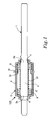
- Fig. 1 shows in a side view and partly in section a weatherproof low friction spindle unit 100 according to the present invention.
- the unit incorporates an elongated shaft 1, having a central portion 2 of bigger diameter provided between the ends of the shaft, and having sloping annular end surfaces 2a, 2b, interconnecting the central portion 2 with the rest of the shaft.
- a bearing housing 3 is provided to enclose a portion of the shaft 1 thereby also the central portion 2 and the sloping annular end surfaces 2a, 2b.
- the spindle unit 100 thus designed can be manufactured and delivered to the end user as a closed sealed off unit encapsulated in the bearing housing 3.
- Fig. 3 is schematically illustrated in perspective another application for the spindle unit 100 according to the invention, where two such spindle units 100 are used in a wind gauge 30, having a tubular housing, which by action of the wind on a wind vane 31 will turn the wind gauge housing 30 to indicate the direction of the wind via a position sensor, associated with one of the spindle units 100.
- the other spindle unit 100 is associated with a wind impeller 32, which via a speed sensing member associated with the second spindle unit indicates the current wind speed.
Landscapes
- Engineering & Computer Science (AREA)
- General Engineering & Computer Science (AREA)
- Mechanical Engineering (AREA)
- Environmental Sciences (AREA)
- Life Sciences & Earth Sciences (AREA)
- Physics & Mathematics (AREA)
- General Physics & Mathematics (AREA)
- Biodiversity & Conservation Biology (AREA)
- Animal Husbandry (AREA)
- Aviation & Aerospace Engineering (AREA)
- Rolling Contact Bearings (AREA)
- Support Of The Bearing (AREA)
- Sealing Of Bearings (AREA)
- Glass Compositions (AREA)
- Mounting Of Bearings Or Others (AREA)
- Spinning Or Twisting Of Yarns (AREA)
- Sliding-Contact Bearings (AREA)
- Rolls And Other Rotary Bodies (AREA)
Abstract
Description
- The present invention refers to a weatherproof low friction spindle unit intended to be incorporated in rotary systems, requiring high stability and aiming at low friction losses, and particularly in rotary systems operating under conditions where dirt, dust, water or other liquids frequently can splash over the spindle unit.
- Such spindle units can for instance be used in hobby articles, toys, measuring instruments and e.g. for fishing reels for supporting the spool thereof in a manner giving a reliable and smooth operation and also being advantageous from noise aspects, etcetera.
- Such a spindle unit is disclosed e.g. in SE-C2-518 489. This earlier known spindle unit referred to a precision spindle unit for low friction performance, which incorporated a tubular housing, preferably made of aluminium with an external anodic coating and surrounding a shaft, a first locating rolling bearing mounted on the shaft, a fixed locking washer with a flange, engaging the inner race ring of the first rolling bearing, to arrest this axially against a shoulder on the shaft, a second rolling bearing in the housing having a loose fit on the shaft, a second locking washer fitted to the shaft, a resilient member provided between the second locking washer and the inner race ring of the second bearing, facing outwards, a shoulder projecting inwards inwardly in the housing, against which shoulder the side of the inwardly directed outer race ring of the second rolling bearing is engaging, whereby the second bearing by influence from the resilient member is biased between the resilient member and the first inwardly facing shoulder in the housing, the locking washers to define a slot seal at each axial side of the housing, whereby each one of the first and the second rolling bearings, at their outwardly facing sides are provided with an integral labyrinth seal.
- The main purpose of the spindle unit disclosed in that patent was to provide a precision spindle unit having very good running properties, and this was also achieved although the resulting spindle unit was so expensive to manufacture that it could be used only for applications where a very high demand for low friction properties where at hand.
- Now therefore the purpose of the present invention is to provide a weatherproof low friction spindle unit having high quality performance, but being substantially less expensive in manufacture, and this has been achieved with a spindle unit which has been given the features defined in the accompanying
claim 1. - Hereinafter the invention will be further described with reference to non-limiting embodiments illustrated in the accompanying drawings.
- Fig. 1 is a side view showing a spindle unit according to the invention, partly in section.
- Fig. 2 is a side view corresponding to Fig. 1 showing the spindle unit according to Fig. 1 in an application for a fishing reel, also shown in cross-section and in simplified form.
- Fig. 3 illustrates use of two spindle units according to the invention in an application for a wind measuring instrument, shown without a portion of the outer casing.
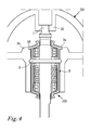
- Fig. 4 is a schematic view of a part of the wind measuring instrument shown in Fig. 3, in bigger scale and with portions of the instrument casing and the spindle unit housing removed.
- Fig. 5 is a perspective view of half a housing for a spindle unit according to the invention.
- Fig. 6 illustrates in a planar view and in bigger scale the housing half shown in Fig. 5.
- Fig. 1 shows in a side view and partly in section a weatherproof low
friction spindle unit 100 according to the present invention. The unit incorporates anelongated shaft 1, having acentral portion 2 of bigger diameter provided between the ends of the shaft, and having slopingannular end surfaces central portion 2 with the rest of the shaft. A bearinghousing 3 is provided to enclose a portion of theshaft 1 thereby also thecentral portion 2 and the slopingannular end surfaces - The bearing
housing 3 shown is made in two identic halves, only one of which is shown in the drawing, and which is made as a semicircular tubular shell, having means 4, 5 for centering, interconnecting and locking two such bearing housing halves in a substantially water tight manner, and the design of which means is further illustrated in and described in connection to Fig. 5. - Due to the two-part design of the bearing
housing 3 it has now become possible to let the bearing housing itself have axial end portions 6, 7 closely adjoining to the slopingend surfaces central portion 2 of theshaft 1 and the shaft surface axially outside thecentral portion 2. The bearing housing halves furthermore are designed with bearing seats intended to receive a locatingbearing 8 and anon-locating bearing 9, which are mounted axially spaced apart on thecentral portion 2 of the shaft. Thenon-locating bearing 9 is biased in an axial direction away from the locatingbearing 8, by means of aresilient member 10, in the embodiment shown as a spring positioned around thecentral portion 2 of the shaft and acting between the inner race rings of the twobearings - When assembling this spindle unit 100 a first housing half is first positioned with its opening facing upwards, a
shaft 1 with thebearings spring 10 positioned on thecentral portion 2 is thereupon lowered down into the first housing half, whereby it is ascertained that thebearings shaft 1 and the inner wall of the bearing housing halves, will form a labyrinth, which in most cases will form a labyrinth seal giving sufficient sealing effect.
When the shaft thus has been positioned in the first bearinghousing half 3, the second (not shown) housing half is positioned thereover, with the cooperating interconnecting means 4, 5 of the housing halves engaging each other. The two housing halves are thereupon secured against each other by means of a connectingmember 11 or by glue. As the spindle unit in question is generally intended for rather modest loads, and most often is mounted in a housing enclosing and locking the spindle halves, this connecting member can preferably, as illustrated be an elastic O-ring member 11, positioned in agroove 12 formed in the outer envelope surface of the bearing housing halves. - The
spindle unit 100 thus designed can be manufactured and delivered to the end user as a closed sealed off unit encapsulated in the bearinghousing 3. - As illustrated in Fig. 2 this
spindle unit 100 can be used in afishing reel 20 shown in cross section, and it can readily be understood that thespindle unit 100 can be inserted from the left hand side in the illustration, axially in the interior of thereel 20, where it can be moved to correct position with aid of the interconnecting means 11 - the O-ring keeping together the housing halves - which can be brought to enter acircumferential groove 21 in the interior of thereel 20. Thespindle unit 100 is axially secured in position in thereel 20 between ashoulder 20a in the reel and the O-ring 11. Alid 22 and alocking ring 23 are positioned at opposite axial ends of theeel 20. - In Fig. 3 is schematically illustrated in perspective another application for the
spindle unit 100 according to the invention, where twosuch spindle units 100 are used in awind gauge 30, having a tubular housing, which by action of the wind on awind vane 31 will turn thewind gauge housing 30 to indicate the direction of the wind via a position sensor, associated with one of thespindle units 100. Theother spindle unit 100 is associated with awind impeller 32, which via a speed sensing member associated with the second spindle unit indicates the current wind speed. - Fig. 4 illustrates in a planar, cross sectional view an upper portion of such a wind gauge application of the
spindle unit 100 according to the invention, where a spindle unit of substantially the same design as that shown in Fig. 1 is used. The major difference as compared to the earlier illustrated embodiment, is that the bearinghousing 3 at one axial end has an externalcircumferential bulb 3a, adapted to fit into acorresponding recess 33 in acentral hub structure 34 in thewind gauge housing 30, thereby being axially arrested between this recess and the O-ring. Theshaft 1 projecting out from the bearinghousing 3 is arranged to cooperate with awind direction indicator 35 arranged in thewind gauge housing 30 for establishing indications representative for the wind direction. A not further shown sensor is positioned within the gauge housing for producing electric signals representative for the or wind speed. These signals can be transferred or transmitted to external processing and/or recording means. - In Fig. 5 is shown in perspective one bearing
housing half 3 in accordance with that shown in Fig. 4, i.e. with an external,circumferential bulb 3a adjacent one axial end thereof. Except for this additional bulb, the mainly tubular bearinghousing half 3 is similar to that illustrated in Figs. 1 and 2, and the description associated with this figure is valid also for the embodiment without such external bulb. - The shell-formed wall of the
housing 3 has at one axial end aportion 13 bordered bywall portions seat 13 for the locating bearing 8 (see Fig. 1). In this view it can clearly be seen that one of the longitudinal side edges of the bearinghousing half 3 has agroove 4, whereas the opposite side edge has a corresponding, projectingridge 5, which groove 4 andridge 5 function as the cooperating means 4, 5 interconnecting the bearinghousing halves 3 in a manner ascertaining that the halves are centered and preventing passage of dirt, dust or moisture therethrough. - Fig. 6 shows in a planar view the bearing
housing half 3 illustrated in Fig. 1, although the only difference compared to the housing half illustrated in Fig. 5 is that thehousing half 3 in this embodiment has no external circumferential bulb. - As can be seen the
groove 4 and theridge 5, follow the somewhat windling contour of the housing side edges, thereby being offset from a linear direction and for this reason it is ascertained that the two parts of the bearinghousing 3 will be positioned in exactly correct mutual positions when they are put together. The form of thegroove 4 andridge 5 being complementary to each other also secures a tight joint between the housing halves, whereby the risk for leakage of dirt, dust and moisture into thespindle unit 100 is substantially eliminated. - Fig. 6 illustrates the restriction of the
bearing seat 13 for the locating bearing 8 (Fig. 1) by the dependingwall portions wall portion 16 of the bearing housing at the opposite axial end thereof, thereby being urged against this wall portion under influence of the resilient force exerted by the spring member 10 (Fig. 1). - The actual design of the outer envelope surface of the bearing housing of course is to be adapted to the purpose for which the spindle unit is intended. In the embodiments illustrated and described the different embodiments of
spindle unit 100 are substantially similar, but it is evident that exterior of the spindle unit can be altered to be appropriate for different applications. - The bearing
housing halves 3 are preferably manufactured from appropriate plastic materials, preferably by injection moulding, although other appropriate manufacturing techniques are also possible. - Although the different applications of the invention has been shown with deep groove ball bearings, it is of course evident that other types of bearings can be used and the invention is further not limited to the embodiments shown and described, but modifications and variants are possible within the scope of the appended claims
- Although the means for interconnecting the bearing housing halves have been shown and described as a groove and tongue joint, it is also possible that the centering and locking of the bearing housing halves can be produced with pins and corresponding bores, although the weather-proof performance will probably be somewhat lower with such a solution.
Claims (9)
- A weatherproof low friction spindle unit (100), incorporating in combination:characterized therein,an elongated shaft (1, 2),a tubular housing (3) surrounding the shaft and having a bigger inner diameter than the diameter of the shaft (1, 2),in the interior of the housing a locating rolling bearing (8) mounted on the shaft and a non-locating rolling bearing (9) provided in the interior of the housing (3) on the shaft,whereby the first and second bearings (8, 9) are spaced apart along the shaft,
that the bearing housing is made as two identic halves (3), each of which forming a semi-tubular shell-formed member, having radii of varying size in the longitudinal direction thereof, with end portions (14, 16) closely adjoining to the shaft (1), and each being provided with means (4, 5) adapted to interconnect the two bearing housing halves in a centered and substantially weatherproof manner. - A weatherproof spindle unit (100) as claimed in claim 1,
characterized therein,
that the locating bearing (8) is held in position in the housing (3) in a bearing seat (13) formed between two depending wall portions (14, 15) in the interior of the housing (3). - A weatherproof spindle unit (100) as claimed in claim 2,
characterized therein,
that the non-locating bearing (9) is arranged against a further depending wall portion (16) in the bearing housing (3) opposed to the bearing seat (13) for the locating bearing, and that a resilient means (10) is provided for biasing the non-locating bearing (9) against said further depending wall portion (16). - A weatherproof spindle unit (100) as claimed in anyone of claims 1-3,
characterized therein,
that each one of the two identic halves (3) of the bearing housing has longitudinal side edges, one of which is provided with a groove (4) extending along the contour of the bearing housing half, whereas the opposite longitudinal side edge has a projecting ridge (5) extending along the contour of the bearing housing half, said groove (4) and ridge (5) being complementary to each other, and forming the means (4, 5) adapted to interconnect the two bearing housing halves in a tight joint, when the bearing housing halves are positioned to enclose the shaft (1, 2) and the bearings (8, 9). - A weatherproof spindle unit (100) as claimed in anyone of claims 1-4,
characterized therein,
that the two bearing housing halves (3) of the spindle unit (100) in their assembled state are held together by at least one resilient connecting member (11) positioned in an associated groove (12) in the outer envelope surface of the bearing housing halves (3). - A weatherproof spindle unit (100) as claimed in anyone of the preceeding claims,
characterized therein,
that the two bearing housing halves (3) are injection moulded plastic material members. - A weatherproof spindle unit (100) as claimed in anyone of the preceeding claims,
characterized therein,
that the shaft (1) has a central portion (2) of slightly bigger diameter than the rest of the shaft (1), with two annular sloping end faces (2a, 2b) spaced apart from each other and positioned adjacent the depending end portions (14, 16) of the bearing housing (3) and forming with the shaft surface there outside labyrinth-shaped sealing arrangements. - A fishing reel (20),
characterized therein,
that it incorporates a spindle unit (100) as claimed in anyone of the preceding claims, and which spindle unit (100) is positioned in the interior of the fishing reel by means of a resilient locking member (11) received in grooves (12, 21) in the exterior of the spindle unit (100) and the interior of the fishing reel (20). - A wind gauge (30),
characterized therein,
that it incorporates at least one spindle unit (100) as claimed in anyone of the preceding claims, and which spindle unit is arranged to cooperate with sensor means and/or (35) a wind direction indicator for establishing wind direction and/or wind speed.
Applications Claiming Priority (2)
| Application Number | Priority Date | Filing Date | Title |
|---|---|---|---|
| SE0400103 | 2004-01-20 | ||
| SE0400103A SE526365C2 (en) | 2004-01-20 | 2004-01-20 | Weatherproof spindle unit with low friction, fishing reel and wind gauge |
Publications (2)
| Publication Number | Publication Date |
|---|---|
| EP1557578A1 true EP1557578A1 (en) | 2005-07-27 |
| EP1557578B1 EP1557578B1 (en) | 2007-02-28 |
Family
ID=31493074
Family Applications (1)
| Application Number | Title | Priority Date | Filing Date |
|---|---|---|---|
| EP05100283A Expired - Lifetime EP1557578B1 (en) | 2004-01-20 | 2005-01-18 | Weatherproof low friction spindle unit |
Country Status (7)
| Country | Link |
|---|---|
| US (1) | US7125172B2 (en) |
| EP (1) | EP1557578B1 (en) |
| JP (1) | JP4160553B2 (en) |
| CN (1) | CN100376816C (en) |
| AT (1) | ATE355470T1 (en) |
| DE (1) | DE602005000602T2 (en) |
| SE (1) | SE526365C2 (en) |
Cited By (4)
| Publication number | Priority date | Publication date | Assignee | Title |
|---|---|---|---|---|
| WO2010097608A1 (en) | 2009-02-24 | 2010-09-02 | Dyson Technology Limited | Rotor assembly |
| US8864460B2 (en) | 2011-08-26 | 2014-10-21 | Dyson Technology Limited | Bearing assembly |
| US9624940B2 (en) | 2009-02-24 | 2017-04-18 | Dyson Technology Limited | Rotor assembly |
| CN111810298A (en) * | 2020-08-13 | 2020-10-23 | 无锡市胜途海泰机电有限公司 | Three-ball bearing turbocharger |
Families Citing this family (5)
| Publication number | Priority date | Publication date | Assignee | Title |
|---|---|---|---|---|
| US7673588B2 (en) * | 2006-09-27 | 2010-03-09 | Head David T | Retractable rotatable pet tether |
| US7750518B1 (en) * | 2006-11-29 | 2010-07-06 | Active Power, Inc. | Transient energy systems and methods for use of the same |
| CN101487849B (en) * | 2008-12-20 | 2011-11-16 | 奇瑞汽车股份有限公司 | Wind velocity measuring element and method |
| DE102018204133A1 (en) * | 2018-03-19 | 2019-09-19 | Minebea Mitsumi Inc. | Rotary anode bearing for an X-ray tube and rotating anode for an X-ray tube |
| CN111251182B (en) * | 2020-03-31 | 2024-11-08 | 王士友 | An independent grinding spindle for external cylindrical grinding |
Citations (4)
| Publication number | Priority date | Publication date | Assignee | Title |
|---|---|---|---|---|
| GB1431678A (en) * | 1972-06-26 | 1976-04-14 | Peugeot Aciers Et Outillage | Device for fastening and adjusting the position of a member in a machine case |
| US4131245A (en) * | 1977-01-31 | 1978-12-26 | Shimano Industrial Company Limited | Fishing reel having an improved drag mechanism |
| EP1228687A1 (en) * | 2001-02-01 | 2002-08-07 | Aktiebolaget SKF | Precision spindle unit for low friction performance |
| JP2003302418A (en) * | 2002-04-08 | 2003-10-24 | Ogasawara Keiki Seisakusho:Kk | Anemometer and anemometer |
Family Cites Families (2)
| Publication number | Priority date | Publication date | Assignee | Title |
|---|---|---|---|---|
| US1583914A (en) * | 1921-11-21 | 1926-05-11 | Antifriction Shafting Bearing | Ball bearing |
| US3639019A (en) * | 1969-07-01 | 1972-02-01 | Schaeffler Ohg Industriewerk | Radial ball bearings |
-
2004
- 2004-01-20 SE SE0400103A patent/SE526365C2/en not_active IP Right Cessation
- 2004-12-13 JP JP2004359836A patent/JP4160553B2/en not_active Expired - Fee Related
-
2005
- 2005-01-13 CN CNB2005100043506A patent/CN100376816C/en not_active Expired - Fee Related
- 2005-01-18 AT AT05100283T patent/ATE355470T1/en not_active IP Right Cessation
- 2005-01-18 EP EP05100283A patent/EP1557578B1/en not_active Expired - Lifetime
- 2005-01-18 DE DE602005000602T patent/DE602005000602T2/en not_active Expired - Lifetime
- 2005-01-21 US US11/038,405 patent/US7125172B2/en not_active Expired - Lifetime
Patent Citations (4)
| Publication number | Priority date | Publication date | Assignee | Title |
|---|---|---|---|---|
| GB1431678A (en) * | 1972-06-26 | 1976-04-14 | Peugeot Aciers Et Outillage | Device for fastening and adjusting the position of a member in a machine case |
| US4131245A (en) * | 1977-01-31 | 1978-12-26 | Shimano Industrial Company Limited | Fishing reel having an improved drag mechanism |
| EP1228687A1 (en) * | 2001-02-01 | 2002-08-07 | Aktiebolaget SKF | Precision spindle unit for low friction performance |
| JP2003302418A (en) * | 2002-04-08 | 2003-10-24 | Ogasawara Keiki Seisakusho:Kk | Anemometer and anemometer |
Non-Patent Citations (1)
| Title |
|---|
| PATENT ABSTRACTS OF JAPAN vol. 2003, no. 12 5 December 2003 (2003-12-05) * |
Cited By (6)
| Publication number | Priority date | Publication date | Assignee | Title |
|---|---|---|---|---|
| WO2010097608A1 (en) | 2009-02-24 | 2010-09-02 | Dyson Technology Limited | Rotor assembly |
| GB2467966B (en) * | 2009-02-24 | 2013-04-03 | Dyson Technology Ltd | Rotor assembly |
| US9624940B2 (en) | 2009-02-24 | 2017-04-18 | Dyson Technology Limited | Rotor assembly |
| US8864460B2 (en) | 2011-08-26 | 2014-10-21 | Dyson Technology Limited | Bearing assembly |
| EP2562436B1 (en) * | 2011-08-26 | 2016-06-01 | Dyson Technology Limited | Bearing Assembly |
| CN111810298A (en) * | 2020-08-13 | 2020-10-23 | 无锡市胜途海泰机电有限公司 | Three-ball bearing turbocharger |
Also Published As
| Publication number | Publication date |
|---|---|
| SE0400103D0 (en) | 2004-01-20 |
| US20050157967A1 (en) | 2005-07-21 |
| JP4160553B2 (en) | 2008-10-01 |
| SE526365C2 (en) | 2005-08-30 |
| EP1557578B1 (en) | 2007-02-28 |
| JP2005207583A (en) | 2005-08-04 |
| DE602005000602D1 (en) | 2007-04-12 |
| DE602005000602T2 (en) | 2008-01-10 |
| SE0400103L (en) | 2005-07-21 |
| CN100376816C (en) | 2008-03-26 |
| CN1644945A (en) | 2005-07-27 |
| ATE355470T1 (en) | 2006-03-15 |
| US7125172B2 (en) | 2006-10-24 |
Similar Documents
| Publication | Publication Date | Title |
|---|---|---|
| US5195830A (en) | Leaktight sensor assembly which can be incorporated in a data sensor bearing and bearing equipped with such an assembly | |
| JP5085568B2 (en) | Shaft support device for electric motor and its mounting method | |
| EP1557578B1 (en) | Weatherproof low friction spindle unit | |
| CN101535817B (en) | Rolling bearing with rotation sensor | |
| TWI776014B (en) | Ball bearing cage and ball bearing | |
| EP1228687B1 (en) | Precision spindle unit for low friction performance | |
| US11649856B2 (en) | Ball bearing cage and ball bearing | |
| US8534126B2 (en) | Sensor mounting cover for a rolling-contact bearing | |
| US12313122B2 (en) | Bearing unit with reinforced retention cage | |
| US5711617A (en) | Dustcap for bearing assembly | |
| US10024363B2 (en) | Rolling bearing assembly | |
| US4281838A (en) | Seal | |
| US9505264B2 (en) | Cover for a wheel-hub bearing | |
| JP6135424B2 (en) | Manufacturing method of rolling bearing unit with seal | |
| CN211901311U (en) | hub unit bearing | |
| CN212155264U (en) | End cover assembly, cross-flow fan blade supporting structure, cross-flow fan blade assembly and air conditioner | |
| JP2012513566A (en) | Bearing assembly | |
| US12152632B2 (en) | Roller bearing | |
| JP2005233321A (en) | Encoder device and rolling bearing provided with the encoder device | |
| US20030118259A1 (en) | Plastic bearing apparatus with split spanner bushing | |
| US4515418A (en) | Bearing assembly with stamped races | |
| JP7081342B2 (en) | Wheel bearing device | |
| JP5359039B2 (en) | Rolling bearing unit with physical quantity measuring device | |
| CN214578360U (en) | Balance car and rotating shaft seat thereof | |
| CN202674031U (en) | Rolling bearing with sensor |
Legal Events
| Date | Code | Title | Description |
|---|---|---|---|
| PUAI | Public reference made under article 153(3) epc to a published international application that has entered the european phase |
Free format text: ORIGINAL CODE: 0009012 |
|
| AK | Designated contracting states |
Kind code of ref document: A1 Designated state(s): AT BE BG CH CY CZ DE DK EE ES FI FR GB GR HU IE IS IT LI LT LU MC NL PL PT RO SE SI SK TR |
|
| AX | Request for extension of the european patent |
Extension state: AL BA HR LV MK YU |
|
| 17P | Request for examination filed |
Effective date: 20060127 |
|
| AKX | Designation fees paid |
Designated state(s): AT BE BG CH CY CZ DE DK EE ES FI FR GB GR HU IE IS IT LI LT LU MC NL PL PT RO SE SI SK TR |
|
| AXX | Extension fees paid |
Extension state: MK Payment date: 20060127 Extension state: HR Payment date: 20060127 Extension state: BA Payment date: 20060127 Extension state: YU Payment date: 20060127 Extension state: AL Payment date: 20060127 Extension state: LV Payment date: 20060127 |
|
| GRAP | Despatch of communication of intention to grant a patent |
Free format text: ORIGINAL CODE: EPIDOSNIGR1 |
|
| GRAS | Grant fee paid |
Free format text: ORIGINAL CODE: EPIDOSNIGR3 |
|
| GRAA | (expected) grant |
Free format text: ORIGINAL CODE: 0009210 |
|
| AK | Designated contracting states |
Kind code of ref document: B1 Designated state(s): AT BE BG CH CY CZ DE DK EE ES FI FR GB GR HU IE IS IT LI LT LU MC NL PL PT RO SE SI SK TR |
|
| AX | Request for extension of the european patent |
Extension state: AL BA HR LV MK YU |
|
| PG25 | Lapsed in a contracting state [announced via postgrant information from national office to epo] |
Ref country code: LI Free format text: LAPSE BECAUSE OF FAILURE TO SUBMIT A TRANSLATION OF THE DESCRIPTION OR TO PAY THE FEE WITHIN THE PRESCRIBED TIME-LIMIT Effective date: 20070228 Ref country code: AT Free format text: LAPSE BECAUSE OF FAILURE TO SUBMIT A TRANSLATION OF THE DESCRIPTION OR TO PAY THE FEE WITHIN THE PRESCRIBED TIME-LIMIT Effective date: 20070228 Ref country code: PL Free format text: LAPSE BECAUSE OF FAILURE TO SUBMIT A TRANSLATION OF THE DESCRIPTION OR TO PAY THE FEE WITHIN THE PRESCRIBED TIME-LIMIT Effective date: 20070228 Ref country code: FI Free format text: LAPSE BECAUSE OF FAILURE TO SUBMIT A TRANSLATION OF THE DESCRIPTION OR TO PAY THE FEE WITHIN THE PRESCRIBED TIME-LIMIT Effective date: 20070228 Ref country code: NL Free format text: LAPSE BECAUSE OF FAILURE TO SUBMIT A TRANSLATION OF THE DESCRIPTION OR TO PAY THE FEE WITHIN THE PRESCRIBED TIME-LIMIT Effective date: 20070228 Ref country code: DK Free format text: LAPSE BECAUSE OF FAILURE TO SUBMIT A TRANSLATION OF THE DESCRIPTION OR TO PAY THE FEE WITHIN THE PRESCRIBED TIME-LIMIT Effective date: 20070228 Ref country code: BE Free format text: LAPSE BECAUSE OF FAILURE TO SUBMIT A TRANSLATION OF THE DESCRIPTION OR TO PAY THE FEE WITHIN THE PRESCRIBED TIME-LIMIT Effective date: 20070228 Ref country code: SI Free format text: LAPSE BECAUSE OF FAILURE TO SUBMIT A TRANSLATION OF THE DESCRIPTION OR TO PAY THE FEE WITHIN THE PRESCRIBED TIME-LIMIT Effective date: 20070228 Ref country code: CH Free format text: LAPSE BECAUSE OF FAILURE TO SUBMIT A TRANSLATION OF THE DESCRIPTION OR TO PAY THE FEE WITHIN THE PRESCRIBED TIME-LIMIT Effective date: 20070228 |
|
| REG | Reference to a national code |
Ref country code: GB Ref legal event code: FG4D |
|
| REG | Reference to a national code |
Ref country code: CH Ref legal event code: EP |
|
| REF | Corresponds to: |
Ref document number: 602005000602 Country of ref document: DE Date of ref document: 20070412 Kind code of ref document: P |
|
| REG | Reference to a national code |
Ref country code: IE Ref legal event code: FG4D |
|
| PG25 | Lapsed in a contracting state [announced via postgrant information from national office to epo] |
Ref country code: BG Free format text: LAPSE BECAUSE OF FAILURE TO SUBMIT A TRANSLATION OF THE DESCRIPTION OR TO PAY THE FEE WITHIN THE PRESCRIBED TIME-LIMIT Effective date: 20070528 |
|
| PG25 | Lapsed in a contracting state [announced via postgrant information from national office to epo] |
Ref country code: SE Free format text: LAPSE BECAUSE OF FAILURE TO SUBMIT A TRANSLATION OF THE DESCRIPTION OR TO PAY THE FEE WITHIN THE PRESCRIBED TIME-LIMIT Effective date: 20070531 |
|
| PG25 | Lapsed in a contracting state [announced via postgrant information from national office to epo] |
Ref country code: ES Free format text: LAPSE BECAUSE OF FAILURE TO SUBMIT A TRANSLATION OF THE DESCRIPTION OR TO PAY THE FEE WITHIN THE PRESCRIBED TIME-LIMIT Effective date: 20070608 |
|
| PG25 | Lapsed in a contracting state [announced via postgrant information from national office to epo] |
Ref country code: IS Free format text: LAPSE BECAUSE OF FAILURE TO SUBMIT A TRANSLATION OF THE DESCRIPTION OR TO PAY THE FEE WITHIN THE PRESCRIBED TIME-LIMIT Effective date: 20070628 |
|
| ET | Fr: translation filed | ||
| PG25 | Lapsed in a contracting state [announced via postgrant information from national office to epo] |
Ref country code: PT Free format text: LAPSE BECAUSE OF FAILURE TO SUBMIT A TRANSLATION OF THE DESCRIPTION OR TO PAY THE FEE WITHIN THE PRESCRIBED TIME-LIMIT Effective date: 20070730 |
|
| NLV1 | Nl: lapsed or annulled due to failure to fulfill the requirements of art. 29p and 29m of the patents act | ||
| REG | Reference to a national code |
Ref country code: CH Ref legal event code: PL |
|
| PG25 | Lapsed in a contracting state [announced via postgrant information from national office to epo] |
Ref country code: SK Free format text: LAPSE BECAUSE OF FAILURE TO SUBMIT A TRANSLATION OF THE DESCRIPTION OR TO PAY THE FEE WITHIN THE PRESCRIBED TIME-LIMIT Effective date: 20070228 |
|
| PG25 | Lapsed in a contracting state [announced via postgrant information from national office to epo] |
Ref country code: CZ Free format text: LAPSE BECAUSE OF FAILURE TO SUBMIT A TRANSLATION OF THE DESCRIPTION OR TO PAY THE FEE WITHIN THE PRESCRIBED TIME-LIMIT Effective date: 20070228 Ref country code: RO Free format text: LAPSE BECAUSE OF FAILURE TO SUBMIT A TRANSLATION OF THE DESCRIPTION OR TO PAY THE FEE WITHIN THE PRESCRIBED TIME-LIMIT Effective date: 20070228 |
|
| PLBE | No opposition filed within time limit |
Free format text: ORIGINAL CODE: 0009261 |
|
| STAA | Information on the status of an ep patent application or granted ep patent |
Free format text: STATUS: NO OPPOSITION FILED WITHIN TIME LIMIT |
|
| 26N | No opposition filed |
Effective date: 20071129 |
|
| PG25 | Lapsed in a contracting state [announced via postgrant information from national office to epo] |
Ref country code: LT Free format text: LAPSE BECAUSE OF FAILURE TO SUBMIT A TRANSLATION OF THE DESCRIPTION OR TO PAY THE FEE WITHIN THE PRESCRIBED TIME-LIMIT Effective date: 20070228 |
|
| PG25 | Lapsed in a contracting state [announced via postgrant information from national office to epo] |
Ref country code: GR Free format text: LAPSE BECAUSE OF FAILURE TO SUBMIT A TRANSLATION OF THE DESCRIPTION OR TO PAY THE FEE WITHIN THE PRESCRIBED TIME-LIMIT Effective date: 20070529 |
|
| PG25 | Lapsed in a contracting state [announced via postgrant information from national office to epo] |
Ref country code: MC Free format text: LAPSE BECAUSE OF NON-PAYMENT OF DUE FEES Effective date: 20080131 |
|
| PG25 | Lapsed in a contracting state [announced via postgrant information from national office to epo] |
Ref country code: EE Free format text: LAPSE BECAUSE OF FAILURE TO SUBMIT A TRANSLATION OF THE DESCRIPTION OR TO PAY THE FEE WITHIN THE PRESCRIBED TIME-LIMIT Effective date: 20070228 Ref country code: IE Free format text: LAPSE BECAUSE OF NON-PAYMENT OF DUE FEES Effective date: 20080118 |
|
| PG25 | Lapsed in a contracting state [announced via postgrant information from national office to epo] |
Ref country code: CY Free format text: LAPSE BECAUSE OF FAILURE TO SUBMIT A TRANSLATION OF THE DESCRIPTION OR TO PAY THE FEE WITHIN THE PRESCRIBED TIME-LIMIT Effective date: 20070228 |
|
| PGFP | Annual fee paid to national office [announced via postgrant information from national office to epo] |
Ref country code: FR Payment date: 20100205 Year of fee payment: 6 Ref country code: IT Payment date: 20100126 Year of fee payment: 6 |
|
| PGFP | Annual fee paid to national office [announced via postgrant information from national office to epo] |
Ref country code: DE Payment date: 20100127 Year of fee payment: 6 Ref country code: GB Payment date: 20100125 Year of fee payment: 6 |
|
| PG25 | Lapsed in a contracting state [announced via postgrant information from national office to epo] |
Ref country code: LU Free format text: LAPSE BECAUSE OF NON-PAYMENT OF DUE FEES Effective date: 20080118 Ref country code: HU Free format text: LAPSE BECAUSE OF FAILURE TO SUBMIT A TRANSLATION OF THE DESCRIPTION OR TO PAY THE FEE WITHIN THE PRESCRIBED TIME-LIMIT Effective date: 20070901 |
|
| PG25 | Lapsed in a contracting state [announced via postgrant information from national office to epo] |
Ref country code: TR Free format text: LAPSE BECAUSE OF FAILURE TO SUBMIT A TRANSLATION OF THE DESCRIPTION OR TO PAY THE FEE WITHIN THE PRESCRIBED TIME-LIMIT Effective date: 20070228 |
|
| GBPC | Gb: european patent ceased through non-payment of renewal fee |
Effective date: 20110118 |
|
| REG | Reference to a national code |
Ref country code: FR Ref legal event code: ST Effective date: 20110930 |
|
| PG25 | Lapsed in a contracting state [announced via postgrant information from national office to epo] |
Ref country code: FR Free format text: LAPSE BECAUSE OF NON-PAYMENT OF DUE FEES Effective date: 20110131 |
|
| PG25 | Lapsed in a contracting state [announced via postgrant information from national office to epo] |
Ref country code: GB Free format text: LAPSE BECAUSE OF NON-PAYMENT OF DUE FEES Effective date: 20110118 |
|
| REG | Reference to a national code |
Ref country code: DE Ref legal event code: R119 Ref document number: 602005000602 Country of ref document: DE Effective date: 20110802 |
|
| PG25 | Lapsed in a contracting state [announced via postgrant information from national office to epo] |
Ref country code: IT Free format text: LAPSE BECAUSE OF NON-PAYMENT OF DUE FEES Effective date: 20110118 |
|
| PG25 | Lapsed in a contracting state [announced via postgrant information from national office to epo] |
Ref country code: DE Free format text: LAPSE BECAUSE OF NON-PAYMENT OF DUE FEES Effective date: 20110802 |