EP1557577A2 - A blind rivet nut - Google Patents
A blind rivet nut Download PDFInfo
- Publication number
- EP1557577A2 EP1557577A2 EP05000366A EP05000366A EP1557577A2 EP 1557577 A2 EP1557577 A2 EP 1557577A2 EP 05000366 A EP05000366 A EP 05000366A EP 05000366 A EP05000366 A EP 05000366A EP 1557577 A2 EP1557577 A2 EP 1557577A2
- Authority
- EP
- European Patent Office
- Prior art keywords
- blind rivet
- rivet nut
- flange
- seal
- further characterised
- Prior art date
- Legal status (The legal status is an assumption and is not a legal conclusion. Google has not performed a legal analysis and makes no representation as to the accuracy of the status listed.)
- Withdrawn
Links
Images

Classifications
-
- F—MECHANICAL ENGINEERING; LIGHTING; HEATING; WEAPONS; BLASTING
- F16—ENGINEERING ELEMENTS AND UNITS; GENERAL MEASURES FOR PRODUCING AND MAINTAINING EFFECTIVE FUNCTIONING OF MACHINES OR INSTALLATIONS; THERMAL INSULATION IN GENERAL
- F16B—DEVICES FOR FASTENING OR SECURING CONSTRUCTIONAL ELEMENTS OR MACHINE PARTS TOGETHER, e.g. NAILS, BOLTS, CIRCLIPS, CLAMPS, CLIPS OR WEDGES; JOINTS OR JOINTING
- F16B19/00—Bolts without screw-thread; Pins, including deformable elements; Rivets
- F16B19/008—Bolts without screw-thread; Pins, including deformable elements; Rivets with sealing means
-
- F—MECHANICAL ENGINEERING; LIGHTING; HEATING; WEAPONS; BLASTING
- F16—ENGINEERING ELEMENTS AND UNITS; GENERAL MEASURES FOR PRODUCING AND MAINTAINING EFFECTIVE FUNCTIONING OF MACHINES OR INSTALLATIONS; THERMAL INSULATION IN GENERAL
- F16B—DEVICES FOR FASTENING OR SECURING CONSTRUCTIONAL ELEMENTS OR MACHINE PARTS TOGETHER, e.g. NAILS, BOLTS, CIRCLIPS, CLAMPS, CLIPS OR WEDGES; JOINTS OR JOINTING
- F16B33/00—Features common to bolt and nut
- F16B33/004—Sealing; Insulation
Definitions
- the present invention relates to a blind rivet nut. More particularly the present invention relates to a blind rivet nut that has improved grip capability and an improved seal.
- Blind rivet nuts are used in thin sheet applications as a means of thread reinforcement and in applications to which a secondary rivet part (bolt) is secured. In some instances these blind rivet nuts are used, for example, to connect an attachment for a rack to the roof of an automobile, where the blind rivet nut is of the so-called closed end variety.
- a blind rivet nut typically has an elongate body, that is generally cylindrical or hexagonal in cross section, and hollow for the major part of its length, with one end being either closed (blind) or open. Part of the hollow portion is threaded to receive a setting tool or bolt.
- a flange is formed at an open end of the blind rivet nut remote from the threaded end and extends laterally therefrom. The flange extends beyond the periphery of the hollow body and has a generally flat face that abuts the surface of an outer layer or sheet of material.
- Installation of the blind rivet nut commences with the blind rivet nut being threaded onto a threaded mandrel of a setting tool and together inserting the blind rivet through preformed apertures of one or more layers of sheets of materials.
- the setting tool mandrel still in engagement in the blind rivet nut, is pulled rearwards towards the flange of the blind rivet nut thereby causing deformation of the blind rivet nut body walls beyond the side of the workpiece remote from the operator and sandwiching the, or each sheet of material, against the face of the flange.
- EP-A-0 634 582 discloses a blind rivet nut having a threaded internal portion and a collar, which is shaped so as to be able to be totally protected against rust, by way of a prior electrolytic coating.
- EP-A-0 634 582 discloses a blind rivet nut having a flange with a recess for receiving an O-ring seal for preventing ingress of moisture.
- blind rivet nuts have proven to be an extremely successful and reliable means of connecting items to outer surfaces of materials, as well as holding a number of layers of materials together.
- a considerable compressive force can be applied to the layers or sheets of material (for example once the elastic limit of the material, from which the blind rivet is formed, has been exceeded and permanent deformation of the rivet has occurred)
- the tolerance of blind rivet nuts to accommodate a range of workpiece thickness is relatively small. That is the actual amount of deformation, and the degree of tolerance in the amount of deformation that occurs, is relatively small.
- An automobile roof often comprises a plurality of layers of different sheets of materials and accordingly there is often a requirement for a number of different lengths of blind rivet nut to be used.
- Each length of blind rivet nut corresponds to its location and use. For example longer length blind rivet nuts are required in positions where there are multiple layers of greater thickness of materials; whereas in other areas, where there may be a smaller number of layers, or less material; shorter blind rivet nuts are employed.
- This requirement for several different lengths of blind rivet nut carries with it the attendant risk that an unsuitable blind rivet nut could be used in a particular thickness of panels with the resultant risk of improper insertion or even failure.
- the additional cost of manufacturing the additional cost of manufacturing tooling for a larger number of blind rivet nut lengths and the associated costs of storage, labelling and distribution.
- a further object of the invention is to provide an improved seal to the flange of a blind rivet nut, for example, to prevent ingress of moisture beneath the flange of the rivet nut and along the body to the interior of the application. Further and particularly where there are several layers of material and the size of the aperture has to be enlarged, in order to ensure sufficient alignment of the holes for the rivet nut to pass through, the flange of the rivet and the associated seal has to be correspondingly large. Further it has been found that, in addition to sealing, it is beneficial to have a wide metal-to-metal contact that the large flange affords in order to give a wider load support area.
- a blind rivet nut for insertion into an aperture formed in one or more layers of material, comprising: an elongate body, said body being substantially hollow and having a longitudinal axis; a flange formed at a plane substantially orthogonal to said axis, said flange being adapted to receive a seal; characterised in that said body has at least one line of weakness formed therein, whereby in use, the body is deformed at or around said at least one line of weakness, thereby enhancing the grip between the blind rivet nut and the or each layer of material(s).
- An advantage of the invention is that it permits blind rivet nuts to be used in situations where the thickness of the material, through which the blind rivet nut passes, varies, thus overcoming the need for a great variety of lengths of blind rivet nut.
- the or each line of weakness is a groove formed in a portion of the hexagon body and is dimensioned and arranged so that material deforms more readily so as to enhance the grip capability of the blind rivet nut.
- the blind rivet is a closed end blind rivet nut and the or each groove is/are machined or formed e.g. by rolling in an outer surface of its collapsible portion.
- the depth of the groove is typically between 0.1 and 0.3 mm.
- the depth of the groove of between 0.1mm and 0.05mm typically is where the wall thickness of the body is at a minimum at the across flats dimension and accordingly is deeper across the comers.
- the grooves are annular recesses formed in a plane parallel with the flange. More than one groove may be provided, in which instance, upon deformation of the body of the blind rivet nut that occurs on setting, radial expansion is exaggerated at a plurality of locations. This results in another advantage of the invention, attributable to the fact that additional lateral grip is provided by the portion(s) of the rivet nut that deform(s) when the, or each, line of weakness is defined in the portion of the rivet nut that sits within the aperture.
- blind rivet nut is employed in several layers of material, relative centres of one hole to another, can vary. In order to accommodate these differences in hole centre location, so as to ensure registration of the holes or apertures, it is common practise to increase hole or aperture sizes in the sheet metals pressings. These holes are sometimes referred to as being oversize.
- the joint in a combination of layers or panels, particularly in roof construction, is required to be watertight and in order to prevent the ingress of moisture the blind rivet nut flange tends to be large so that it overlaps such oversize holes.
- Flanges by themselves are not watertight and some sealing capability such as an 'O-ring' seal beneath the flange or a moulded peripheral rim seal to the flange needs to be added.
- the dimensions of the seal groove are such that on application of the blind rivet nut, when setting occurs, the seal is compressed to the correct degree to effect a seal between the flange and the outer face if the workpiece. If the seal groove is too deep then the degree of compression will not be enough to prevent ingress of moisture.
- the pre-punched holes in the panels are of different sizes and accordingly the size and form of the panels can be considerably oversize in relation to the size of the blind rivet nut.
- a corollary of this is that holes formed in each sheet of material have to be oversize so as to provide a small amount of tolerance when aligning multiple layers, with the result that flanges of blind rivets have also to be considerably larger than the body of the blind rivet to ensure there is sufficient material provided by the face of the flange to abut against the peripheral regions of the aperture, as well as to accommodate a sealing ring for preventing the ingress of moisture.
- the larger flange diameter provides a wider bearing area to support such a load especially if there is metal to metal contact i.e. there is minimum compression of the seal.
- a blind rivet nut comprising: an elongate body, said body being substantially hollow and having a longitudinal axis; a flange formed at a first end of said body, the flange having a first portion removed, defining a recess for receiving a seal; characterised in that a second portion is removed from said flange, whereby in use, the seal is permitted to deform laterally from the first portion so as to form a seal in the second portion. Since the seal is allowed to deform laterally to fill the gap between thee workpiece and the second portion thus preventing the ingress of moisture this allows the face of the underside of the flange to press against the workpiece thus giving a metal-to-metal contact.
- the second portion is an annular recess machined at a peripheral region of the flange so as to accommodate the seal thereby forming a water ingress resistant seal in the vicinity of the circumference of the flange.
- blind rivet nut with grooves for enhancing the grip capability of the blind rivet nut and also the provision of a seal for preventing ingress of moisture into the holes and between sheets of materials and also providing a larger area to support the applied loads by virtue of the larger flange.
- a blind rivet is considered to be particularly well suited for use in either single or multiple layers of material.
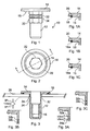
- blind rivet nut 10 having a body 12 and a flange 14.
- Blind rivet nut 10 has an internally threaded portion 16 and is in the form of a fully machined, standard closed end blind rivet nut with a hexagon form 22 along the portion of the shank of the blind rivet nut which abuts the underside face 15 of flange 14.
- Formed or machined in face 15 is an annular recess 20 which forms a location for the seal 18 as shown in Figure 1A.
- Alternative forms of seal are in Figures 1B showing hemispherical shape 18a and 1C showing a square seal 18b.
- the hexagon form 22 of the blind rivet nut 10 is shaped so as to enter corresponding hexagon shaped holes or apertures 24 in work piece panel 26 and on setting, provides resistance to a torque applied orthogonal to the longitudinal axis of the blind rivet nut 10, for example on application of a securing bolt (not shown).
- Figures 1, 3, 3A, 5 and 6 show two grooves 32 and 34, although there can be as little as one or more than two, in the hexagon portion 22 of the body 12. These grooves 32 and 34 are circumferential and are formed about the longitudinal axis of the blind rivet nut 10. The grooves 32 and 34 are shown as 'v' shape sections in Figure 3A where the groove progressively narrows towards its smaller diameter. This shape is readily achievable using conventional machining or rolling operations.
- the section of the grooves may vary. For instance as shown in Figure 3 the grooves are 'v' shaped with a 60 degrees inclusive angle and 1.5mm wide at the widest point. Other variants are shown in Figures 3A, 3B and 3C showing semicircular, square and rectangular shapes respectively.
- the purpose of the groves 32 and 34 is to provide a section whereby the blind rivet nut under an axial setting load will collapse preferentially to shorten the body of the rivet nut followed by expansion of the intermediate sections of the blind rivet body, thereby ensuring a better grip range is achieved.
- the cross sectional shape of the grooves 32 and 34 could be rectangular, where the depth of the groove is greater than its width, or square, where the width is greater than its depth.
- the purpose of the grooves 32 and 34 is to provide a stress concentration when setting (inserting) the blind rivet nut 10 and therefore promote prompt, controlled and predictable material deformation, thereby ensuring a better grip is achieved between the blind rivet nut 10 and the sheet(s) of material 26 in which it is set.
- blind rivet nut 10 has a grip range of 2mm, whereas that of a conventional blind rivet nut is typically approximately 1mm.
- Figure 4 shows an upper part of the blind rivet nut 10 and depicts in detail the flange 14 that is considerably larger than normal.
- the diameter of the flange 14 can be 20 mm to 30 mm but is ideally around 23mm in diameter instead of the standard 13 mm diameter.
- the underside of the flange 14 is divided into two areas; one being the angular area defined by the face 15 that extends from the abutment of the body 22 to the inner diameter of the recess 20 and the other being the annular area 17 defined between the outer diameter of the recess 20 and the outer diameter of the flange 14 but of a different thickness that is defined by the gap 40.
- the purpose of the gap 40 is to allow the seal 18 when under compression to extrude through the gap 40 when the recess 20 has been filed and thus allows both sealing and a metal to metal contact of the face 15 against the workpiece material as shown in Figure 5A.
- the O-ring seal 18 is made form a rubber-like material such as Neoprene (Trade Mark) or a similar elastomeric material.
- the shape of the seal can be a circular cross-section such as an O-ring or even flat, providing the material protrudes beyond the recess 40, above the face of the underside surface of the flange 40 sufficiently to form a water ingress resistant seal between the flange 40 and the work piece 26.
- Blind rivet nut 10 is threaded onto a mandrel of a setting tool (not shown) and pushed into the or each hole 24 formed in one or more work pieces 26. It is then set in the conventional manner by supporting the flange 14 of the blind rivet nut on the nosepiece of the setting tool (not shown) and drawing the mandrel and the co-operating thread portion 16 of the blind rivet nut towards the blind side of the workpiece 26. In this process the portion of the body 12 of the blind rivet nut 10 adjacent the threaded portion 16 collapses to form a radially enlarged region on the opposite side of the material or work piece 26 from flange 14.
- the radial expansion of the body of the blind rivet nut also occurs within the holes 24 of the workpiece 26 thus promoting hole filling and increase joint integrity. There is sufficient force applied during the setting operation to permanently deform a part of the rivet nut so as to grip underside of the work piece 26 thereby providing intimate face-to-face contact occurs. Typical settings are shown giving settings in maximum and minimum grip thickness.
Landscapes
- Engineering & Computer Science (AREA)
- General Engineering & Computer Science (AREA)
- Mechanical Engineering (AREA)
- Insertion Pins And Rivets (AREA)
- Dowels (AREA)
- Fittings On The Vehicle Exterior For Carrying Loads, And Devices For Holding Or Mounting Articles (AREA)
Abstract
Description
Claims (15)
- A blind rivet nut (10) for insertion into an aperture (24) formed in one or more layers of material (26), comprising: an elongate body (12), said body (12) being substantially hollow and having a longitudinal axis; a flange (14) formed at a plane substantially orthogonal to said axis, characterised in that said body (12) has at least one line of weakness (32, 34) formed therein, whereby in use, the body (12) is deformed at or around said at least one line of weakness (32,34), thereby enhancing the grip between the blind rivet nut (10) and the or each layer of material (26).
- A blind rivet nut (10) according to claim 1 further characterised in that, said flange (14) is adapted to receive a seal (18).
- A blind rivet nut (10) according to claim 1 or 2 further characterised in that the, or each, line of weakness (32, 34) is in the form of a groove formed in the body of the nut (10).
- A blind rivet nut (10) according to claim 3 further characterised in that the, or each, groove (32, 34) is formed in an hexagonal portion (22) of the body (12) of the blind rivet nut (10).
- A blind rivet nut according to any of claims 3 or 4 further characterised in that the groove is v-shaped.
- A blind rivet nut according to claim 5 further characterised in that the angle at which the v-shaped groove is cut is greater than 40° and less than 80° and is preferably substantially 60°.
- A blind rivet nut according to claim 3 further characterised in that the blind rivet nut body has a U-shaped groove formed therein.
- A blind rivet nut according to claim 1 further characterised in that the, or each, line of weakness (32, 34) is in the form of a channel formed in the body (12) of the nut (10).
- A blind rivet nut according to claim 1 further characterised in that the blind rivet nut body has a plurality of grooves formed therein.
- A blind rivet nut according to claim 1 further characterised in that the blind rivet nut body is in the form of a cylinder.
- A blind rivet nut (10), comprising: an elongate body (12), said body (12) being substantially hollow and having a longitudinal axis; a flange (14) formed at a first end of said body (12), the flange (14) having a first portion removed defining a recess (20) for receiving a seal (18); characterised in that a second portion (40) is removed from said flange (14), whereby in use, the seal (18) is permitted to deform laterally from the first portion (20) so as to form a seal in the second portion (40) thereby creating a larger sealing surface.
- A blind rivet nut (10) according to claim 11 further characterised in that the second portion (40) is an annular recess formed at a peripheral region of the flange (14) so as to accommodate the seal (18), thereby forming a seal extending to the vicinity of the circumference of the flange (14).
- A blind rivet nut (10) according to claim 11 further characterised in that the seal (18) is moulded around the rim of the flange (14).
- A blind rivet nut (10) having a flange (14) and a body (12) the ratio of the diameter of the flange (14) to the length of the body (12) being greater than 0.75, preferably greater than 0.85.
- A plurality of panels (26) held together with the blind rivet nut (10) according to any of claims 1 to 14.
Applications Claiming Priority (2)
| Application Number | Priority Date | Filing Date | Title |
|---|---|---|---|
| GB0401206A GB2410306A (en) | 2004-01-21 | 2004-01-21 | Blind rivet nut having a weakened portion |
| GB0401206 | 2004-01-21 |
Publications (2)
| Publication Number | Publication Date |
|---|---|
| EP1557577A2 true EP1557577A2 (en) | 2005-07-27 |
| EP1557577A3 EP1557577A3 (en) | 2006-05-17 |
Family
ID=31971147
Family Applications (1)
| Application Number | Title | Priority Date | Filing Date |
|---|---|---|---|
| EP05000366A Withdrawn EP1557577A3 (en) | 2004-01-21 | 2005-01-11 | A blind rivet nut |
Country Status (4)
| Country | Link |
|---|---|
| US (1) | US20050201844A1 (en) |
| EP (1) | EP1557577A3 (en) |
| JP (1) | JP2005207594A (en) |
| GB (1) | GB2410306A (en) |
Cited By (6)
| Publication number | Priority date | Publication date | Assignee | Title |
|---|---|---|---|---|
| EP1918596A1 (en) | 2006-11-03 | 2008-05-07 | Herbert Schruff | Blind rivet and use thereof |
| DE102007019253A1 (en) | 2007-04-24 | 2008-11-06 | Gesipa Blindniettechnik Gmbh | Blind rivet nut for connecting component i.e. fluid container, has shaft with radially weakened sections, which are formed by recesses, where recesses are divided in peripheral direction and are diametrically arranged opposite to each other |
| WO2016189026A1 (en) * | 2015-05-25 | 2016-12-01 | Nuovo Pignone Tecnologie Srl | Method for assembling equipment on a support of a turbomachine |
| FR3063121A1 (en) * | 2017-02-22 | 2018-08-24 | Bollhoff Otalu S.A. | CRYSTAL INSERT, ELEMENT AND FIXING ASSEMBLY COMPRISING SUCH AN INSERT AND METHODS OF MANUFACTURING SUCH PIECES. |
| DE102018103138A1 (en) | 2018-02-13 | 2019-08-14 | Bombardier Transportation Gmbh | Rivet thread element and component arrangement with rivet thread element |
| EP3885589A1 (en) * | 2020-03-25 | 2021-09-29 | Bollhoff Otalu S.A. | Blind rivet insert, a component with an installed blind rivet insert and method for installing such a blind rivet insert in a component opening |
Families Citing this family (21)
| Publication number | Priority date | Publication date | Assignee | Title |
|---|---|---|---|---|
| GB2427251B (en) * | 2005-06-14 | 2008-07-02 | Newfrey Llc | A blind rivet, removal system and related method |
| US20060291974A1 (en) * | 2005-06-28 | 2006-12-28 | Mcgee Thomas | Nut insert |
| AT504622B1 (en) * | 2006-11-30 | 2008-10-15 | Singh Sumanjit Dr | RIVET |
| DE102007005626B3 (en) * | 2007-02-05 | 2008-08-28 | Honsel Umformtechnik Gmbh | Blind rivet nut or threaded bolt |
| DE102007040371A1 (en) * | 2007-08-20 | 2009-02-26 | Adolf Würth GmbH & Co. KG | Rivet |
| US8529177B2 (en) * | 2010-02-15 | 2013-09-10 | Polaris Fastening Consulting, Llc | Integrated pin/sleeve blind fastener |
| JP6048733B2 (en) * | 2012-10-31 | 2016-12-21 | ポップリベット・ファスナー株式会社 | Blind rivet and sealing structure using the same |
| US9404521B2 (en) | 2012-12-12 | 2016-08-02 | Polaris Fastening Consulting, Llc | Self integrating structural insert sleeve |
| DE102013214247A1 (en) | 2013-07-22 | 2015-01-22 | Bayerische Motoren Werke Aktiengesellschaft | Blind rivet nut for connecting two components |
| CN105626657B (en) * | 2014-10-28 | 2018-09-11 | 上海汽车集团股份有限公司 | Riveting nut |
| US10220435B2 (en) | 2015-08-26 | 2019-03-05 | Polaris Fastener Testing And Tooling, Llc | Installation tooling system for buckle and swage type fastener |
| US9868475B2 (en) | 2016-01-08 | 2018-01-16 | Honda Motor Co., Ltd. | Multi-material joint assembly, joint and method for a vehicle |
| EP3807543B1 (en) * | 2018-06-12 | 2026-05-13 | Sherex Fastening Solutions LLC | Rivet-like fastener and compression seal assembly |
| CN108916193A (en) * | 2018-07-05 | 2018-11-30 | 宁波敏实汽车零部件技术研发有限公司 | The aluminum cell pallet connection structure of rivet nut and the fixed battery modules of application rivet nut |
| JP7139183B2 (en) * | 2018-07-31 | 2022-09-20 | ポップリベット・ファスナー株式会社 | blind bolt |
| US11421720B2 (en) | 2019-01-15 | 2022-08-23 | Whirlpool Corporation | Retention device for supporting a component and method of use |
| US11441588B1 (en) * | 2021-03-31 | 2022-09-13 | Bright Power Inc. | Equipment mounting systems and processes thereof |
| CA3225818A1 (en) * | 2021-08-19 | 2023-02-23 | Arnaud Brunet | Fastening collars, multi-piece fasteners, and methods for fastening |
| CN114060389A (en) * | 2021-11-24 | 2022-02-18 | 宾科汽车紧固件(昆山)有限公司 | Sealing rivet nut, forming device for sealing rivet nut and preparation method |
| US20230302527A1 (en) * | 2022-03-28 | 2023-09-28 | Raytheon Company | Resilient fastener system and resilient fastener insert |
| SE547776C2 (en) * | 2024-07-10 | 2025-11-25 | Bulten Fasteners Ab | Method for cold forming a fastening device comprising a captive o-ring |
Family Cites Families (15)
| Publication number | Priority date | Publication date | Assignee | Title |
|---|---|---|---|---|
| US1365719A (en) * | 1919-08-18 | 1921-01-18 | Ogden John Edward | Machine-bolt anchor |
| USRE20055E (en) * | 1932-03-31 | 1936-08-04 | Rivet and method of setting | |
| US2324142A (en) * | 1941-04-03 | 1943-07-13 | Rolyan Corp | Rivet and method of making same |
| US2887926A (en) * | 1956-07-30 | 1959-05-26 | Illinois Tool Works | Plastic fastening device with foldable shank |
| US3304830A (en) * | 1960-08-09 | 1967-02-21 | Goodrich Co B F | Expansible hollow rivet having a polygonal shank |
| US3136203A (en) * | 1960-11-29 | 1964-06-09 | Gen Dynamics Corp | Blind rivet having means for retaining the expansion bolt |
| BE795670A (en) * | 1972-02-22 | 1973-06-18 | Dunlop Ltd | WHEEL IMPROVEMENTS |
| FR2569792B1 (en) * | 1984-09-03 | 1987-12-18 | Otalu Sa | WATERPROOF TAPULAR TUBULAR RIVET |
| US4869629A (en) * | 1988-07-22 | 1989-09-26 | Textron Inc. | Blind fastener |
| DE9304575U1 (en) * | 1992-09-23 | 1993-05-27 | Gesellschaft für Befestigungstechnik Gebr. Titgemeyer GmbH & Co. KG, 4500 Osnabrück | Rivet connection |
| BE1007284A3 (en) * | 1993-07-12 | 1995-05-09 | Dejond Naamloze Vennootschap E | Rivet bolt. |
| GB9504095D0 (en) * | 1995-03-01 | 1995-04-19 | Emhart Inc | Improved blind rivet |
| GB2310904B (en) * | 1996-03-08 | 1999-11-24 | Emhart Inc | Improved blind rivet |
| GB0107664D0 (en) * | 2001-03-28 | 2001-05-16 | Emhart Inc | Blind rivet nut with improved seal retention |
| US6761520B1 (en) * | 2003-05-09 | 2004-07-13 | Pem Management, Inc. | Clinch-type blind nut |
-
2004
- 2004-01-21 GB GB0401206A patent/GB2410306A/en not_active Withdrawn
-
2005
- 2005-01-11 EP EP05000366A patent/EP1557577A3/en not_active Withdrawn
- 2005-01-17 US US11/037,426 patent/US20050201844A1/en not_active Abandoned
- 2005-01-20 JP JP2005012518A patent/JP2005207594A/en active Pending
Cited By (16)
| Publication number | Priority date | Publication date | Assignee | Title |
|---|---|---|---|---|
| EP1918596A1 (en) | 2006-11-03 | 2008-05-07 | Herbert Schruff | Blind rivet and use thereof |
| EP1918596B1 (en) * | 2006-11-03 | 2012-03-21 | Herbert Schruff | Blind rivet and use thereof |
| DE102007019253A1 (en) | 2007-04-24 | 2008-11-06 | Gesipa Blindniettechnik Gmbh | Blind rivet nut for connecting component i.e. fluid container, has shaft with radially weakened sections, which are formed by recesses, where recesses are divided in peripheral direction and are diametrically arranged opposite to each other |
| DE102007019253B4 (en) * | 2007-04-24 | 2010-05-06 | Gesipa Blindniettechnik Gmbh | blind rivet nut |
| DE102007019253C5 (en) * | 2007-04-24 | 2013-07-04 | Gesipa Blindniettechnik Gmbh | blind rivet nut |
| WO2016189026A1 (en) * | 2015-05-25 | 2016-12-01 | Nuovo Pignone Tecnologie Srl | Method for assembling equipment on a support of a turbomachine |
| CN108026784A (en) * | 2015-05-25 | 2018-05-11 | 诺沃皮尼奥内技术股份有限公司 | Method for assembling equipment on a support of a turbomachine |
| EP3366932A1 (en) * | 2017-02-22 | 2018-08-29 | Bollhoff Otalu S.A. | Crimping insert, attachment element and assembly comprising such an insert and methods for manufacturing such parts |
| FR3063121A1 (en) * | 2017-02-22 | 2018-08-24 | Bollhoff Otalu S.A. | CRYSTAL INSERT, ELEMENT AND FIXING ASSEMBLY COMPRISING SUCH AN INSERT AND METHODS OF MANUFACTURING SUCH PIECES. |
| US10920813B2 (en) | 2017-02-22 | 2021-02-16 | Bollhoff Otalu S.A. | Insert to be crimped, fixing part and assembly comprising one such insert and methods for manufacturing such parts |
| DE102018103138A1 (en) | 2018-02-13 | 2019-08-14 | Bombardier Transportation Gmbh | Rivet thread element and component arrangement with rivet thread element |
| EP3885589A1 (en) * | 2020-03-25 | 2021-09-29 | Bollhoff Otalu S.A. | Blind rivet insert, a component with an installed blind rivet insert and method for installing such a blind rivet insert in a component opening |
| WO2021190951A1 (en) * | 2020-03-25 | 2021-09-30 | Bollhoff Otalu S.A. | Blind rivet insert, a component with an installed blind rivet insert and method for installing such a blind rivet insert in a component opening |
| JP2022547743A (en) * | 2020-03-25 | 2022-11-15 | ベルホフ オタル エス.エー | Blind rivet inserts, members fitted with blind rivet inserts and methods of installing such blind rivet inserts in member openings |
| JP7198390B2 (en) | 2020-03-25 | 2022-12-28 | ベルホフ オタル エス.エー | Blind rivet inserts, members fitted with blind rivet inserts and methods of installing such blind rivet inserts in member openings |
| US11686338B2 (en) | 2020-03-25 | 2023-06-27 | Bollhoff Otalu S.A. | Blind rivet insert, a component with an installed blind rivet insert and method for installing such a blind rivet insert in a component opening |
Also Published As
| Publication number | Publication date |
|---|---|
| GB0401206D0 (en) | 2004-02-25 |
| GB2410306A (en) | 2005-07-27 |
| US20050201844A1 (en) | 2005-09-15 |
| EP1557577A3 (en) | 2006-05-17 |
| JP2005207594A (en) | 2005-08-04 |
Similar Documents
| Publication | Publication Date | Title |
|---|---|---|
| US20050201844A1 (en) | Blind rivet nut | |
| US8291795B2 (en) | Fastener system with stable engagement and stick fit | |
| KR102063126B1 (en) | Blind rivet bolt | |
| US6276040B1 (en) | Element, method of attaching the element to a plate-like component, component assembly and die buttons | |
| EP0864766B1 (en) | Component assembly, method of attaching an element to a plate-like component to form a component assembly and die button for carrying out this method | |
| US20020106263A1 (en) | Nut and method for its fabrication | |
| CA2128448A1 (en) | Female clinch fastener with cold-formed locking flange and associated installation method | |
| EP1194699B1 (en) | Pierce nut | |
| US20080260494A1 (en) | Methods and apparatus for coupling gas turbine engine components | |
| US20090151519A1 (en) | Dual socket for fast pace assembly environment | |
| CA2816439C (en) | Method and device for locking a support ring to a scaffolding column | |
| EP3938666B1 (en) | Bolted joint using deformable sleeve with longitudinal grooves | |
| US20210071800A1 (en) | Press seal with an elastomer body and a tensioning bolt | |
| KR20220002338A (en) | Blind Rivet Nuts, How to Place and Set Blind Rivet Nuts | |
| CA2700370C (en) | Low clearance socket and drive system | |
| US4466762A (en) | Tool for forming internal screw threads | |
| EP1506842A1 (en) | Socket for tightening, loosening or holding a hexagonal part underneath an equally sized hexagonal nut | |
| US20040231470A1 (en) | Protective socket having strengthened tool-drive hole | |
| JPH0140323Y2 (en) | ||
| JP2000129910A (en) | Wall tie mounting bolt for sacaffold | |
| KR20250105437A (en) | Fastening system with sealing arrangement | |
| US20240369091A1 (en) | Fastening system with sealing arrangement | |
| JP7175732B2 (en) | Fastening structure for reinforcement | |
| EP1273793A2 (en) | Screw locking device for blocking the rotation of a screw element | |
| JPH11280159A (en) | Joints for steel pipe structures |
Legal Events
| Date | Code | Title | Description |
|---|---|---|---|
| PUAI | Public reference made under article 153(3) epc to a published international application that has entered the european phase |
Free format text: ORIGINAL CODE: 0009012 |
|
| AK | Designated contracting states |
Kind code of ref document: A2 Designated state(s): AT BE BG CH CY CZ DE DK EE ES FI FR GB GR HU IE IS IT LI LT LU MC NL PL PT RO SE SI SK TR |
|
| AX | Request for extension of the european patent |
Extension state: AL BA HR LV MK YU |
|
| PUAL | Search report despatched |
Free format text: ORIGINAL CODE: 0009013 |
|
| AK | Designated contracting states |
Kind code of ref document: A3 Designated state(s): AT BE BG CH CY CZ DE DK EE ES FI FR GB GR HU IE IS IT LI LT LU MC NL PL PT RO SE SI SK TR |
|
| AX | Request for extension of the european patent |
Extension state: AL BA HR LV MK YU |
|
| AKX | Designation fees paid | ||
| STAA | Information on the status of an ep patent application or granted ep patent |
Free format text: STATUS: THE APPLICATION IS DEEMED TO BE WITHDRAWN |
|
| 18D | Application deemed to be withdrawn |
Effective date: 20061118 |
|
| REG | Reference to a national code |
Ref country code: DE Ref legal event code: 8566 |