EP1557229B1 - Apparatus and method for reducing operating stress in a turbine blade and the like - Google Patents
Apparatus and method for reducing operating stress in a turbine blade and the like Download PDFInfo
- Publication number
- EP1557229B1 EP1557229B1 EP04292556A EP04292556A EP1557229B1 EP 1557229 B1 EP1557229 B1 EP 1557229B1 EP 04292556 A EP04292556 A EP 04292556A EP 04292556 A EP04292556 A EP 04292556A EP 1557229 B1 EP1557229 B1 EP 1557229B1
- Authority
- EP
- European Patent Office
- Prior art keywords
- radius
- core
- metal part
- radii
- center point
- Prior art date
- Legal status (The legal status is an assumption and is not a legal conclusion. Google has not performed a legal analysis and makes no representation as to the accuracy of the status listed.)
- Expired - Lifetime
Links
- 238000000034 method Methods 0.000 title claims description 25
- 238000005266 casting Methods 0.000 claims description 37
- 239000002184 metal Substances 0.000 claims description 25
- 239000000919 ceramic Substances 0.000 claims description 16
- 239000007787 solid Substances 0.000 claims description 15
- 238000001816 cooling Methods 0.000 claims description 8
- 239000000463 material Substances 0.000 claims description 6
- 238000004519 manufacturing process Methods 0.000 claims description 5
- 239000002002 slurry Substances 0.000 claims description 5
- 238000010438 heat treatment Methods 0.000 claims description 4
- 238000003754 machining Methods 0.000 claims description 4
- 239000002131 composite material Substances 0.000 claims description 3
- 238000001035 drying Methods 0.000 claims description 3
- 238000002844 melting Methods 0.000 claims description 3
- 230000008018 melting Effects 0.000 claims description 3
- 238000005162 X-ray Laue diffraction Methods 0.000 claims description 2
- 238000005530 etching Methods 0.000 claims 1
- 239000011162 core material Substances 0.000 description 40
- 230000035882 stress Effects 0.000 description 20
- 239000007789 gas Substances 0.000 description 9
- 239000002826 coolant Substances 0.000 description 2
- 239000012467 final product Substances 0.000 description 2
- 230000001788 irregular Effects 0.000 description 2
- 239000002253 acid Substances 0.000 description 1
- 238000004458 analytical method Methods 0.000 description 1
- 239000011449 brick Substances 0.000 description 1
- 239000000567 combustion gas Substances 0.000 description 1
- 239000012530 fluid Substances 0.000 description 1
- 239000000446 fuel Substances 0.000 description 1
- 229910001092 metal group alloy Inorganic materials 0.000 description 1
- 239000000203 mixture Substances 0.000 description 1
- 239000000047 product Substances 0.000 description 1
- 230000003068 static effect Effects 0.000 description 1
- 230000008646 thermal stress Effects 0.000 description 1
Images


Classifications
-
- B—PERFORMING OPERATIONS; TRANSPORTING
- B22—CASTING; POWDER METALLURGY
- B22C—FOUNDRY MOULDING
- B22C9/00—Moulds or cores; Moulding processes
- B22C9/02—Sand moulds or like moulds for shaped castings
- B22C9/04—Use of lost patterns
-
- B—PERFORMING OPERATIONS; TRANSPORTING
- B22—CASTING; POWDER METALLURGY
- B22C—FOUNDRY MOULDING
- B22C9/00—Moulds or cores; Moulding processes
- B22C9/10—Cores; Manufacture or installation of cores
Definitions
- the present disclosure generally relates to a method and apparatus for designing and manufacturing a cast part to minimize mechanical operating stress, and more particularly to minimizing operating stress in a turbine blade.
- Component casting is typically used when large quantities of identical products are being produced or when design specifications require intricate internal geometry that machining apparatus such as mills, drill presses, and/or lathes cannot access.
- Highly stressed components such as turbine blades in gas turbine engines require casting techniques that minimize localized stress caused by internal geometric features.
- Turbine blades, and the like have internal hollow portions to reduce the weight of the blade and provide passages for cooling air flow. Cooling air flow is required because the external operating temperatures of the exhaust gas flow exceed the melting temperature of metal alloys used in gas turbine engines.
- Turbine blades with cooling passages and stress reducing methods are known in the prior art.
- U.S. Patent No. 6,533,547 issued to Anding et al. on March 18, 2003 discloses a turbine blade having internal space through which coolant fluid is guided and in which stiffening ribs are formed to reinforce and support the external walls. Coolant screens that reduce the cooling of the stiffening ribs are arranged in front of the stiffening ribs in order to reduce thermal stresses.
- Cores for casting turbine blades are typically made of ceramic composite or the like. Casting cores have solid portions separated by hollow portions. The solid portions of the core form hollow portions in the final product, likewise the hollow portions of the core are where the metal portions are formed in the final product. The solid portions of the casting core will fracture if not supported adequately during the manufacturing process. To prevent core fracture, support elements or "tie features" are designed in the core to extend between adjacent solid portions. These support elements necessarily produce through apertures in the internal walls of the turbine blade. It would be desirable to design these elements to provide adequate mechanical support to the core, while at the same time minimizing operating stress that the resulting through apertures cause in the turbine blade.
- a core for casting a metal part as claimed in claim 1 is provided.
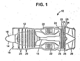
- FIG. 1 is a cross-section of a typical gas turbine engine
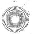
- FIG. 2 is a front view of a turbine rotor
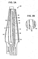
- FIG. 3A is a side view of a casting core for a turbine blade
- FIG. 3B is an enlarged view of a portion of FIG. 3A showing a support element
- FIG. 4 is a cross-sectional view of the support element of FIG. 3A ;
- FIG. 5 is a perspective view rotor blade partially cut-away to show the casting core of Fig. 3A ;
- FIG. 6 is a portion of the cast turbine blade after the core has been removed to show internal passages of the turbine blade
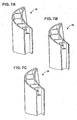
- FIG. 7A is a portion of the turbine blade showing an irregular aperture formed from an undefined casting support element
- FIG. 7B is a portion of the turbine blade showing an circular aperture formed from a casting support element having a circular cross section
- FIG. 7C is a portion of the turbine blade showing an aperture formed from a casting support element having a cross section defined by the present disclosure.
- the present disclosure provides for an apparatus design and method for minimizing operating stress on parts manufactured by a casting process.
- the cast part is a turbine blade for a gas turbine engine, however, the cast part can be any of the type having complex internal geometry and subjected to high stresses during operation.
- the design and method can be used for both moving and static geometry.
- the gas turbine engine 10 includes an outer case 12 to hold the internal turbo-machinery components and to attach the engine 10 to an aerospace vehicle (not shown).
- the gas turbine engine 10 includes a rotor 14 that includes a shaft 15 extending from the front of the engine to the rear of the engine.
- the casing 12 forms an inlet 18 in which air enters past a nosecone 16 and into the engine 10.
- the rotor can include an axial compressor 20 having at least one stage.
- the compressor 20 is operable for compressing the air and delivering the compressed air to a combustor 22.
- the combustor 22 receives the compressed air and a fuel to burn therein.
- the combustion gas mixture expands at high velocity through a turbine 24 having at least one stage.
- a turbine stator 25 can be positioned between each turbine rotor stage to remove unsteady vortices and unstructured flow patterns to provide a predetermined velocity profile of the gas flow prior to entering the next stage of the turbine 24.
- a nozzle 26 accelerates the flow exiting the turbine 24 to increase the velocity mass flow which generates the thrust to propel the aerospace vehicle.
- the turbine rotor 24 has a plurality of blades 30 connected to a turbine disk 31.
- the turbine rotor 24 spins a high rotational speed. This high rotational speed produces a large centripetal force which creates large stresses inside the turbine blade. Additional stress is imparted on the turbine blades 30 when impacted by the high velocity air. Further stress can be generated due to thermal gradients formed during operation of the engine 10.
- Engine components are designed to minimize weight to achieve specified performance, but must maintain durability and reliability for a given design lifespan. To meet these performance goals and design life requirements, stress producing features such as internal holes and fillets must be designed to minimize local stress around those areas.
- the casting core 32 can be made of a ceramic or other composite materials designed to withstand the high temperatures and pressures generated during the casting process.
- the casting core produces the mirror image of itself in the final turbine blade 30.
- the casting core 32 has solid portions 34 spaced apart by hollow portions 36.
- the solid portions 34 form the internal cavities of the turbine blade 30 and the hollow portions 36 form the metal portions of the turbine blade 30.
- the turbine core 32 requires at least one support element 38 to extend between adjacent solid portions 34 through a hollow portion 36 to prevent the core from fracturing during the casting process.
- FIG. 3B shows an enlarged portion of the core 32 having a support element 38.
- the support element 38 has a cross-sectional shape optimized to prevent the core from fracturing during the casting process and to minimize operating mechanical stress in the area of the metal part formed by the support element 38.
- a cross-section 40 of the support element 38 is shown in FIG. 4 .
- the cross-section is designed with generic curves defined below by several radii and corresponding arcs.
- the cross-section 40 can be scaled to a desired size for a given core 32.
- the cross section defines a shape that minimizes stress in the cast part.
- the cross-section 40 includes a first radius R1, a second radius R2, and a third radius R3 each defined by a center point 42, 44, and 46 respectively.
- the first radius R1 defines a circumferential arc 48
- the second radius R2 defines a circumferential arc 50
- the third radius R3 defines a circumferential arc 52.
- the center point 42 of the first radius R1 and the center point 44 of the second radius R2 are separated by a first distance D1.
- the center point 44 of the radius R2 is separated a distance D2 from the center point 46 of the third radius R3.
- a fourth radius R4 having a center point 54 is positioned such that a circumferential arcs 56 defined by the radius R4 is positioned to be simultaneously tangent to the circumferential arcs 48, 50, 52 of the first, second and third radii R1, R2, R3 respectively.
- a fifth radius R5 having a center point 58 defines a circumferential arc 60 that is positioned opposite of the arc 56 of the fourth radius R4.
- the circumferential arc 60 of the fifth radius R5 is positioned so as to be simultaneously tangent to the first, second and third circumferential arcs 48,50,52 of the first, second and third radii R1, R2, R3 respectively.
- the cross-section 40 is bounded by the arcs 56, 60 of the fourth and fifth radii on the sides thereof and by the intersection of the arcs 56, 60 of the fourth and fifth radii at each end thereof.
- the first and third radii R1, R3 can be substantially equal in length and the fourth and fifth radii R4, R5 can also be substantially equal in length.
- the first distance D1 can be substantially equal in length to the second distance D2.
- Each of the circumferential arcs 48, 50, 52, 56, and 60 can be defined by a higher order curve that approximates a circular arc formed by a radius.
- the higher order curve could be a spine curve or a B-spine curve, but is not necessarily limited to those particular definitions.
- a ceramic slurry is injected into a core die (not shown) to form a green core.
- the core die forms solid portions 34 spaced apart by corresponding hollow portions 36, and at least one support element 38 extending between adjacent solid core portions.
- the core 32 is removed from the die and allowed to completely dry. After drying, the core 32 is then heated at a predetermined temperature to increase material strength.
- the outer surface of the core 32 is process treated to increase strength prior to machining the core to final dimensional specifications.
- the cross-section 40 of the at least one support element 38 may be formed according to the method described above.
- a method for forming a cast part with a ceramic core having at least one support element 38 element having a cross-section 40 design to minimize operational stress in the cast part as well as provide stiffening support for the core 32 during the casting process is also contemplated by the present disclosure.
- the method includes forming a wax die (not shown) to define the external geometry of the cast part.
- the casting core 32 is inserted into the wax die.
- Wax is then injected into the wax die to form a wax pattern of the external shape of the cast part.
- Ceramic slurry is then introduced into the wax pattern to form a mold shell.
- the mold is dried and the wax is removed by heating the mold to a predetermined temperature to melt the wax. This heating process also increases the strength of the ceramic mold.
- the ceramic mold is cooled to a predetermined temperature and then preheated to the approximate melting temperature, of the casting material.
- the molten casting material is then poured into the mold.
- the mold is cooled in a controlled environment.
- the casting mold shell is removed from the cast part and the casting core 32 is leached with acid of a type known in the art to remove the ceramic core from the cast part.
- the cast part is then inspected with N-ray to verify that all of the core material has been removed.
- the surface of the cast part is etched and a laue'ding procedure is performed to inspect the grain structure of the cast part and ensure structural integrity.
- the surface of the cast part is then inspected with a fluorescent penetrate to determine whether any flaws such as cracks have formed.
- the internal features of the cast part are inspected with X-ray.
- the cast part is then finish machined and inspected to final external dimensions. A flow test is performed to determine whether the internal passages were formed correctly.
- FIG. 5 a turbine blade 30 is shown partially cut-away with the ceramic core 32 shown internal thereto.
- FIG. 6 shows an internal structure 70 of the turbine blade 30 after the ceramic core 32 has been removed. More specifically, a plurality of passages 72 is formed in the turbine blade 30 to provide channels for cooling air flow to circulate therein and keep the blade 30 below the design temperature limit.
- Each cooling passage 72 includes a pair of side walls 74 bounded by the external surfaces 76, 78 of the blade 30.
- Each core support element 38 forms a through aperture 80 in the side walls 74 of the air passages 72.
- These apertures 80 cause high stress in localized areas surrounding the aperture 80. As such, it is desirable that the shape of the apertures 80 are designed to minimize the localized stress in the blade 30 according to the method described above.
- FIG. 7A shows a portion of a turbine blade 30 having an irregular aperture 80a formed from an undefined casting support element 38.
- FIG. 7B shows a portion of a turbine blade 30 having a circular aperture 80b formed from a casting support element having a circular cross section.
- FIG. 7C shows a portion of a turbine blade 30 with an aperture formed from a casting support element having a cross section defined by the present disclosure.
- the turbine blade 30 of FIG. 7C was analyzed using Finite Element Analysis (FEA), a computational design tool that allows design engineers to model a particular part and simulate operational loads such as inertial forces, thermal gradients, pressure forces, and the like.
- FEA Finite Element Analysis
- the FEA model analytically breaks the solid part into a series of discreet geometric elements such as "bricks” or “tetrahedrons”, etc, and calculates the stress at each element induced by the simulated operational loads.
- the design study performed lead to the discovery that stress levels associated with the aperture 80c having the newly designed geometry of FIG. 7C were approximately 50% of the stress levels associated with the apertures 80a, 80b shown in FIGS. 7A and 7B .
Landscapes
- Engineering & Computer Science (AREA)
- Mechanical Engineering (AREA)
- Molds, Cores, And Manufacturing Methods Thereof (AREA)
- Turbine Rotor Nozzle Sealing (AREA)
Description
- The invention was made by or under contract with the Navy of the United States Government under contract number N00019-02-C-3003.
- The present disclosure generally relates to a method and apparatus for designing and manufacturing a cast part to minimize mechanical operating stress, and more particularly to minimizing operating stress in a turbine blade.
- Component casting is typically used when large quantities of identical products are being produced or when design specifications require intricate internal geometry that machining apparatus such as mills, drill presses, and/or lathes cannot access. Highly stressed components such as turbine blades in gas turbine engines require casting techniques that minimize localized stress caused by internal geometric features. Turbine blades, and the like, have internal hollow portions to reduce the weight of the blade and provide passages for cooling air flow. Cooling air flow is required because the external operating temperatures of the exhaust gas flow exceed the melting temperature of metal alloys used in gas turbine engines.
- Turbine blades with cooling passages and stress reducing methods are known in the prior art. For example,
U.S. Patent No. 6,533,547 issued to Anding et al. on March 18, 2003, discloses a turbine blade having internal space through which coolant fluid is guided and in which stiffening ribs are formed to reinforce and support the external walls. Coolant screens that reduce the cooling of the stiffening ribs are arranged in front of the stiffening ribs in order to reduce thermal stresses. - Cores for casting turbine blades are typically made of ceramic composite or the like. Casting cores have solid portions separated by hollow portions. The solid portions of the core form hollow portions in the final product, likewise the hollow portions of the core are where the metal portions are formed in the final product. The solid portions of the casting core will fracture if not supported adequately during the manufacturing process. To prevent core fracture, support elements or "tie features" are designed in the core to extend between adjacent solid portions. These support elements necessarily produce through apertures in the internal walls of the turbine blade. It would be desirable to design these elements to provide adequate mechanical support to the core, while at the same time minimizing operating stress that the resulting through apertures cause in the turbine blade.
- In accordance with one aspect of the present invention is provided a core for casting a metal part as claimed in claim 1.
- In accordance with another aspect of the invention is provided, a method for manufacturing a casting core as claimed in
claim 12. - In accordance with another aspect of the invention is provided a method for forming a cast part as claimed in claim 19.
- In accordance with a still further aspect of the invention is provided a cast metal part as claimed in
claim 20. - These and other aspects and features of the disclosure will become more apparent upon reading the following detailed description when taken in conjunction with the accompanying drawings.
-
FIG. 1 is a cross-section of a typical gas turbine engine; -
FIG. 2 is a front view of a turbine rotor; -
FIG. 3A is a side view of a casting core for a turbine blade; -
FIG. 3B is an enlarged view of a portion ofFIG. 3A showing a support element; -
FIG. 4 is a cross-sectional view of the support element ofFIG. 3A ; -
FIG. 5 is a perspective view rotor blade partially cut-away to show the casting core ofFig. 3A ; -
FIG. 6 is a portion of the cast turbine blade after the core has been removed to show internal passages of the turbine blade; -
FIG. 7A is a portion of the turbine blade showing an irregular aperture formed from an undefined casting support element; -
FIG. 7B is a portion of the turbine blade showing an circular aperture formed from a casting support element having a circular cross section; and -
FIG. 7C is a portion of the turbine blade showing an aperture formed from a casting support element having a cross section defined by the present disclosure. - The present disclosure provides for an apparatus design and method for minimizing operating stress on parts manufactured by a casting process. In one embodiment of the present disclosure, the cast part is a turbine blade for a gas turbine engine, however, the cast part can be any of the type having complex internal geometry and subjected to high stresses during operation. The design and method can be used for both moving and static geometry.
- Referring now to
FIG. 1 , a cross-section of a typicalgas turbine engine 10 is shown therein. Thegas turbine engine 10 includes anouter case 12 to hold the internal turbo-machinery components and to attach theengine 10 to an aerospace vehicle (not shown). Thegas turbine engine 10 includes arotor 14 that includes ashaft 15 extending from the front of the engine to the rear of the engine. Thecasing 12 forms aninlet 18 in which air enters past anosecone 16 and into theengine 10. The rotor can include anaxial compressor 20 having at least one stage. Thecompressor 20 is operable for compressing the air and delivering the compressed air to acombustor 22. Thecombustor 22 receives the compressed air and a fuel to burn therein. The combustion gas mixture expands at high velocity through aturbine 24 having at least one stage. Aturbine stator 25 can be positioned between each turbine rotor stage to remove unsteady vortices and unstructured flow patterns to provide a predetermined velocity profile of the gas flow prior to entering the next stage of theturbine 24. Anozzle 26 accelerates the flow exiting theturbine 24 to increase the velocity mass flow which generates the thrust to propel the aerospace vehicle. - Referring now to
FIG. 2 , a view of the turbine rotor is shown therein. Theturbine rotor 24 has a plurality ofblades 30 connected to aturbine disk 31. Theturbine rotor 24 spins a high rotational speed. This high rotational speed produces a large centripetal force which creates large stresses inside the turbine blade. Additional stress is imparted on theturbine blades 30 when impacted by the high velocity air. Further stress can be generated due to thermal gradients formed during operation of theengine 10. Engine components are designed to minimize weight to achieve specified performance, but must maintain durability and reliability for a given design lifespan. To meet these performance goals and design life requirements, stress producing features such as internal holes and fillets must be designed to minimize local stress around those areas. - Referring now to
FIG. 3A , acasting core 32 for aturbine blade 30 is shown therein. The castingcore 32 can be made of a ceramic or other composite materials designed to withstand the high temperatures and pressures generated during the casting process. The casting core produces the mirror image of itself in thefinal turbine blade 30. The castingcore 32 hassolid portions 34 spaced apart byhollow portions 36. Thesolid portions 34 form the internal cavities of theturbine blade 30 and thehollow portions 36 form the metal portions of theturbine blade 30. Theturbine core 32 requires at least onesupport element 38 to extend between adjacentsolid portions 34 through ahollow portion 36 to prevent the core from fracturing during the casting process.FIG. 3B shows an enlarged portion of the core 32 having asupport element 38. Thesupport element 38 has a cross-sectional shape optimized to prevent the core from fracturing during the casting process and to minimize operating mechanical stress in the area of the metal part formed by thesupport element 38. - A
cross-section 40 of thesupport element 38 is shown inFIG. 4 . The cross-section is designed with generic curves defined below by several radii and corresponding arcs. Thecross-section 40 can be scaled to a desired size for a givencore 32. The cross section defines a shape that minimizes stress in the cast part. Thecross-section 40 includes a first radius R1, a second radius R2, and a third radius R3 each defined by acenter point circumferential arc 48, the second radius R2 defines acircumferential arc 50, and the third radius R3 defines acircumferential arc 52. Thecenter point 42 of the first radius R1 and thecenter point 44 of the second radius R2 are separated by a first distance D1. Thecenter point 44 of the radius R2 is separated a distance D2 from thecenter point 46 of the third radius R3. A fourth radius R4 having acenter point 54 is positioned such that a circumferential arcs 56 defined by the radius R4 is positioned to be simultaneously tangent to the circumferential arcs 48, 50, 52 of the first, second and third radii R1, R2, R3 respectively. A fifth radius R5 having acenter point 58 defines acircumferential arc 60 that is positioned opposite of thearc 56 of the fourth radius R4. Thecircumferential arc 60 of the fifth radius R5 is positioned so as to be simultaneously tangent to the first, second and third circumferential arcs 48,50,52 of the first, second and third radii R1, R2, R3 respectively. Thecross-section 40 is bounded by thearcs arcs - According to one embodiment, the first and third radii R1, R3 can be substantially equal in length and the fourth and fifth radii R4, R5 can also be substantially equal in length. Also, the first distance D1 can be substantially equal in length to the second distance D2. Each of the circumferential arcs 48, 50, 52, 56, and 60 can be defined by a higher order curve that approximates a circular arc formed by a radius. For example, the higher order curve could be a spine curve or a B-spine curve, but is not necessarily limited to those particular definitions.
- In order to manufacture a
casting core 32, the following method may be employed. First a ceramic slurry is injected into a core die (not shown) to form a green core. The core die formssolid portions 34 spaced apart by correspondinghollow portions 36, and at least onesupport element 38 extending between adjacent solid core portions. After solidifying, thecore 32 is removed from the die and allowed to completely dry. After drying, thecore 32 is then heated at a predetermined temperature to increase material strength. The outer surface of thecore 32 is process treated to increase strength prior to machining the core to final dimensional specifications. Thecross-section 40 of the at least onesupport element 38 may be formed according to the method described above. - A method for forming a cast part with a ceramic core having at least one
support element 38 element having across-section 40 design to minimize operational stress in the cast part as well as provide stiffening support for the core 32 during the casting process is also contemplated by the present disclosure. The method includes forming a wax die (not shown) to define the external geometry of the cast part. The castingcore 32 is inserted into the wax die. Wax is then injected into the wax die to form a wax pattern of the external shape of the cast part. Ceramic slurry is then introduced into the wax pattern to form a mold shell. The mold is dried and the wax is removed by heating the mold to a predetermined temperature to melt the wax. This heating process also increases the strength of the ceramic mold. The ceramic mold is cooled to a predetermined temperature and then preheated to the approximate melting temperature, of the casting material. The molten casting material is then poured into the mold. The mold is cooled in a controlled environment. The casting mold shell is removed from the cast part and thecasting core 32 is leached with acid of a type known in the art to remove the ceramic core from the cast part. The cast part is then inspected with N-ray to verify that all of the core material has been removed. The surface of the cast part is etched and a laue'ding procedure is performed to inspect the grain structure of the cast part and ensure structural integrity. The surface of the cast part is then inspected with a fluorescent penetrate to determine whether any flaws such as cracks have formed. The internal features of the cast part are inspected with X-ray. The cast part is then finish machined and inspected to final external dimensions. A flow test is performed to determine whether the internal passages were formed correctly. - Referring now to
FIG. 5 , aturbine blade 30 is shown partially cut-away with theceramic core 32 shown internal thereto.FIG. 6 shows aninternal structure 70 of theturbine blade 30 after theceramic core 32 has been removed. More specifically, a plurality ofpassages 72 is formed in theturbine blade 30 to provide channels for cooling air flow to circulate therein and keep theblade 30 below the design temperature limit. Eachcooling passage 72 includes a pair ofside walls 74 bounded by theexternal surfaces blade 30. Eachcore support element 38 forms a throughaperture 80 in theside walls 74 of theair passages 72. Theseapertures 80 cause high stress in localized areas surrounding theaperture 80. As such, it is desirable that the shape of theapertures 80 are designed to minimize the localized stress in theblade 30 according to the method described above. -
FIG. 7A shows a portion of aturbine blade 30 having anirregular aperture 80a formed from an undefinedcasting support element 38.FIG. 7B shows a portion of aturbine blade 30 having acircular aperture 80b formed from a casting support element having a circular cross section.FIG. 7C shows a portion of aturbine blade 30 with an aperture formed from a casting support element having a cross section defined by the present disclosure. Theturbine blade 30 ofFIG. 7C was analyzed using Finite Element Analysis (FEA), a computational design tool that allows design engineers to model a particular part and simulate operational loads such as inertial forces, thermal gradients, pressure forces, and the like. The FEA model analytically breaks the solid part into a series of discreet geometric elements such as "bricks" or "tetrahedrons", etc, and calculates the stress at each element induced by the simulated operational loads. The design study performed lead to the discovery that stress levels associated with theaperture 80c having the newly designed geometry ofFIG. 7C were approximately 50% of the stress levels associated with theapertures FIGS. 7A and 7B . - While certain representative embodiments and details have been shown for purposes of illustrating the disclosure, it will be apparent to those skilled in the art that various changes in the methods and apparatus disclosed herein may be made without departing from the scope of the invention which is defined in the appended claims.
Claims (33)
- A core (32) for casting a metal part, comprising:a body having solid portions (34) spaced apart by hollow portions (36); andat least one support element extending between adjacent solid portions (34), the at least one support element (38) having a shape optimized to prevent the core from fracturing during a casting process and to minimize operating mechanical stress in the area of the metal part formed by the support element, the at least one support element comprising:a cross section (40) having a first radius (R1), a second radius (R2), a third radius (R3), a fourth radius (R4), and a fifth radius (R5), each radius defined by a center point and a circumferential arc;a first distance (D1) defining a length between the center point (42) of the first radius (R1) and the center point (44) of the second radius (R2); anda second distance (D2) defining a length between the center point (44) of the second radius (R2) and the center point (46) of the third radius (R3).
- The core of claim 1, herein the first and third radii (R1, R3) are substantially equal in length.
- The core of claim 1 or 2, wherein the fouth and fifth radii (R4, R5) are substantially equal in length.
- The core of any preceding claim, wherein the first distance (D1) is substantially equal to the second distance (D2).
- The core of any preceding claim, wherein the center point (54) of the fourth radius (R4) is positioned such that the circumferential arc (56) of the fourth radius (R4) is simultaneously tangent to the circumferential arcs (48, 50, 52) of the first, second, and third radii (R1, R2, R3).
- The core of any preceding claim, wherein the center point (58) of the fifth radius (R5) is positioned such that the circumferential arc (60) of the fifth radius (R5) is simultaneously tangent to the circumferential arcs (48, 50, 52) of the first, second, and third radii (R1, R2, R3).
- The core of any preceding claim, wherein the circumferential arcs (56, 60) of the fourth and fifth radii (R4, R5) define opposing sides of the core cross-section (40).
- The core of any preceding claim, wherein each circumferential arc is defined by a higher order curve that approximates a radius.
- The core of claim 8, wherein the higher order curve is a spline.
- The core of claim 8, wherein the higher order curve is a B-spline.
- The core of any preceding claim, wherein the core (32) is made from ceramic composite material.
- A method for manufacturing a core (32) for casting a metal part comprising the steps of:providing ceramic slurry;injecting the slurry into a core die to form a green core with solid portions (34) spaced apart by a corresponding hollow portion (36); andforming at least one support element (38) between adjacent solid core portions, the at least one support element having a shape optimized to prevent the core from fracturing during a casting process and to minimize operating mechanical stress in the area of the metal part formed by the support element,a cross section (40) of the at least one support element (38) formed comprising:a first radius (R1);a second (R1) radius a first distance (D1) from the first radius (R1);a third radius (R3) a second distance (D2) from the second radius (R2);a fourth radius (R4) having a circumference (56) positioned tangent to the circumferences (48,50,52) of the first, second, and third radii (R1, R2, R3); anda fifth radius (R5) having the circumference (60) positioned tangent to the circumferences (48,50,52) of the first, second, and third radii (R1, R2, R3).
- The method of claims 12, further comprising the steps of:removing the core from the die;drying the core; andheating the core at a predetermined temperature to increase material strength.
- The method of claim 12 or 13 further comprising the steps of:treating the surface of the core to increase strength of the core; and machining the core to meet specification dimensions.
- The method of any of claims 12 to 14, wherein the first and second radii (R1,R2) are substantially equal in length.
- The method of any of claims 12 to 15, wherein the fourth and fifth radii (R4,R5) are substantially equal in length.
- The method of any of claims 12 to 16, wherein the first and second distances (D1,D2) are substantially equal in length.
- The method of any of claims 12 to 17, wherein the fourth and fifth radii (R4,R5) are positioned on opposite sides of the support cross-section (40).
- A method for forming a cast part comprising the steps of:forming a ceramic core by a method of any of claims 12 to 18;making a wax die to define external geometry of the cast part;injecting wax into the wax die to form a wax pattern of the cast part;inserting the ceramic core into the wax pattern;injecting ceramic slurry into the wax pattern to form a mold shell; drying the mold shell;removing the wax from the mold;heating the mold to a predetermined temperature to increase the strength of the ceramic mold;cooling the mold to a predetermined temperature;preheating the mold to melting temperature of the casting material;pouring molten casting material into the mold;cooling the mold in a controlled environment;removing the casting mold shell from the cast part;leeching the core from the cast part;inspecting the part with N-ray to verify that the entire core has been removed;etching the surface of the cast part;laue'ding and inspecting the grain structure of the cast part;inspecting the surface of the cast part with fluorescent penetrate;inspecting internal features of the cast part with X-ray;finish machining the external features of the cast part;inspecting the external dimensions of the cast part; andflow testing the internal passages of the cast part.
- A cast metal part, comprising:a solid portion having a cast through aperture therein, said aperture comprising a cross section having a first radius, a second radius, a third radius, a fourth radius, and a fifth radius, each radius defined by a center point and a circumferential arc;a first distance defining a length between the center point of the first radius and the center point of the second radius; anda second distance defining a length between the center point of the second radius and the center point of the third radius.
- The metal part of claim 20, wherein the first and third radii are substantially equal in length.
- The metal part of claim 20 or 21, wherein the forth and fifth radii are substantially equal in length.
- The metal part of claim 20, 21 or 22, wherein the first distance is substantially equal to the second distance.
- The metal part of any of claims 20 to 23, wherein the center point of the fourth radius is positioned such that the circumferential arc of the fourth radius is simultaneously tangent to the circumferential arcs of the first, second, and third radii.
- The metal part of any of claims 20 to 24, wherein the center point of the fifth radius is positioned such that the circumferential arc of the fifth radius is simultaneously tangent to the circumferential arcs of the first, second, and third radii.
- The metal part of any of claims 20 to 25, wherein the circumferential arcs of the fourth and fifth radii define opposing sides of the core cross-section.
- The metal part of any of claims 20 to 26, wherein each circumferential arc is defined by a higher order curve that approximates a radius.
- The metal part of claim 27, wherein the higher order curve is a spline.
- The metal part of claim 27, wherein the higher order curve is a B-spline.
- The metal part of any of claims 20 to 29, wherein the metal part is a moving part.
- The metal part of claim 30, wherein the moving part is a turbine blade.
- The metal part of any of claims 20 to 29, wherein the metal part is a stationary part.
- The metal part of any of claims 20 to 29, wherein the stationary part is a turbine vane.
Applications Claiming Priority (2)
| Application Number | Priority Date | Filing Date | Title |
|---|---|---|---|
| US10/763,611 US7216694B2 (en) | 2004-01-23 | 2004-01-23 | Apparatus and method for reducing operating stress in a turbine blade and the like |
| US763611 | 2004-01-23 |
Publications (3)
| Publication Number | Publication Date |
|---|---|
| EP1557229A2 EP1557229A2 (en) | 2005-07-27 |
| EP1557229A3 EP1557229A3 (en) | 2006-03-08 |
| EP1557229B1 true EP1557229B1 (en) | 2010-04-28 |
Family
ID=34634612
Family Applications (1)
| Application Number | Title | Priority Date | Filing Date |
|---|---|---|---|
| EP04292556A Expired - Lifetime EP1557229B1 (en) | 2004-01-23 | 2004-10-27 | Apparatus and method for reducing operating stress in a turbine blade and the like |
Country Status (6)
| Country | Link |
|---|---|
| US (3) | US7216694B2 (en) |
| EP (1) | EP1557229B1 (en) |
| JP (1) | JP2005205494A (en) |
| KR (1) | KR20050076804A (en) |
| CN (1) | CN1644271A (en) |
| DE (1) | DE602004026820D1 (en) |
Families Citing this family (49)
| Publication number | Priority date | Publication date | Assignee | Title |
|---|---|---|---|---|
| US7216694B2 (en) * | 2004-01-23 | 2007-05-15 | United Technologies Corporation | Apparatus and method for reducing operating stress in a turbine blade and the like |
| GB0412915D0 (en) * | 2004-06-10 | 2004-07-14 | Rolls Royce Plc | Method of making and joining an aerofoil and root |
| US8137611B2 (en) * | 2005-03-17 | 2012-03-20 | Siemens Energy, Inc. | Processing method for solid core ceramic matrix composite airfoil |
| FR2889088B1 (en) * | 2005-07-29 | 2008-08-22 | Snecma | CORE FOR BLADE OF TURBOMACHINE |
| FR2900850B1 (en) | 2006-05-10 | 2009-02-06 | Snecma Sa | PROCESS FOR MANUFACTURING CERAMIC FOUNDRY CORES FOR TURBOMACHINE BLADES |
| US20080028606A1 (en) * | 2006-07-26 | 2008-02-07 | General Electric Company | Low stress turbins bucket |
| US7650926B2 (en) * | 2006-09-28 | 2010-01-26 | United Technologies Corporation | Blade outer air seals, cores, and manufacture methods |
| US7674093B2 (en) * | 2006-12-19 | 2010-03-09 | General Electric Company | Cluster bridged casting core |
| US7857588B2 (en) * | 2007-07-06 | 2010-12-28 | United Technologies Corporation | Reinforced airfoils |
| DE102007054782A1 (en) * | 2007-11-16 | 2009-05-20 | Mtu Aero Engines Gmbh | Induction coil, method and device for inductive heating of metallic components |
| US7639777B2 (en) * | 2008-02-26 | 2009-12-29 | United Technologies Corp. | Computed tomography systems and related methods involving forward collimation |
| US20090213984A1 (en) * | 2008-02-26 | 2009-08-27 | United Technologies Corp. | Computed Tomography Systems and Related Methods Involving Post-Target Collimation |
| US8238521B2 (en) * | 2008-03-06 | 2012-08-07 | United Technologies Corp. | X-ray collimators, and related systems and methods involving such collimators |
| US20090225954A1 (en) * | 2008-03-06 | 2009-09-10 | United Technologies Corp. | X-Ray Collimators, and Related Systems and Methods Involving Such Collimators |
| US7876875B2 (en) * | 2008-04-09 | 2011-01-25 | United Technologies Corp. | Computed tomography systems and related methods involving multi-target inspection |
| US20090274264A1 (en) * | 2008-04-30 | 2009-11-05 | United Technologies Corp. | Computed Tomography Systems and Related Methods Involving Localized Bias |
| US7888647B2 (en) * | 2008-04-30 | 2011-02-15 | United Technologies Corp. | X-ray detector assemblies and related computed tomography systems |
| JP5254675B2 (en) * | 2008-06-16 | 2013-08-07 | 三菱重工業株式会社 | Turbine blade manufacturing core and turbine blade manufacturing method |
| FR2950825B1 (en) * | 2009-10-01 | 2011-12-09 | Snecma | IMPROVED PROCESS FOR MANUFACTURING AN ANNULAR ASSEMBLY FOR LOST WAX TURBOMACHINE, METALLIC MOLD AND WAX MODEL FOR IMPLEMENTING SUCH A METHOD |
| IT1396481B1 (en) | 2009-11-17 | 2012-12-14 | Maprof Sas Di Renzo Moschini E C | METHOD OF MANUFACTURE OF BODIES MONOLITHIC CABLES USING A PROCESS OF CASTING OR INJECTION MOLDING. |
| US8414268B2 (en) * | 2009-11-19 | 2013-04-09 | United Technologies Corporation | Rotor with one-sided load and lock slots |
| US20110135446A1 (en) * | 2009-12-04 | 2011-06-09 | United Technologies Corporation | Castings, Casting Cores, and Methods |
| US8657580B2 (en) * | 2010-06-17 | 2014-02-25 | Pratt & Whitney | Blade retainment system |
| US8647064B2 (en) * | 2010-08-09 | 2014-02-11 | General Electric Company | Bucket assembly cooling apparatus and method for forming the bucket assembly |
| JP5536001B2 (en) * | 2011-09-20 | 2014-07-02 | 株式会社日立製作所 | Gas turbine blade film cooling hole setting method and gas turbine blade |
| US9925584B2 (en) * | 2011-09-29 | 2018-03-27 | United Technologies Corporation | Method and system for die casting a hybrid component |
| US8750561B2 (en) | 2012-02-29 | 2014-06-10 | United Technologies Corporation | Method of detecting material in a part |
| KR101960715B1 (en) * | 2012-08-02 | 2019-03-22 | 한화파워시스템 주식회사 | Method for manufacturing a impeller and Method for manufacturing a turbine wheel |
| US9120144B2 (en) * | 2013-02-06 | 2015-09-01 | Siemens Aktiengesellschaft | Casting core for twisted gas turbine engine airfoil having a twisted rib |
| WO2015126488A2 (en) * | 2013-12-23 | 2015-08-27 | United Technologies Corporation | Lost core structural frame |
| JP6242700B2 (en) | 2014-01-31 | 2017-12-06 | 三菱日立パワーシステムズ株式会社 | Turbine blade manufacturing method |
| CA2857297C (en) * | 2014-07-21 | 2021-08-17 | Alstom Renewable Technologies | Apparatus and method for modifying a geometry of a turbine part |
| US10907609B2 (en) * | 2014-07-15 | 2021-02-02 | Ge Renewable Technologies | Apparatus and method for modifying a geometry of a turbine part |
| FR3037829B1 (en) * | 2015-06-29 | 2017-07-21 | Snecma | CORE FOR MOLDING A DAWN WITH OVERLAPPED CAVITIES AND COMPRISING A DEDUSISHING HOLE THROUGH A CAVITY PARTLY |
| WO2017048683A1 (en) * | 2015-09-17 | 2017-03-23 | Sikorsky Aircraft Corporation | Stress reducing holes |
| CN105195673B (en) * | 2015-10-14 | 2017-08-04 | 江苏大学 | A method of investment casting of bimetal composite cracking connecting rod |
| FR3046736B1 (en) | 2016-01-15 | 2021-04-23 | Safran | REFRACTORY CORE INCLUDING A MAIN BODY AND A SHELL |
| KR102209771B1 (en) * | 2016-05-20 | 2021-01-29 | 한화에어로스페이스 주식회사 | Core for casting turbine blade, manufacturing method thereof, and turbine blade using the same |
| US10443403B2 (en) | 2017-01-23 | 2019-10-15 | General Electric Company | Investment casting core |
| US10626797B2 (en) | 2017-02-15 | 2020-04-21 | General Electric Company | Turbine engine compressor with a cooling circuit |
| CN107243596B (en) * | 2017-05-10 | 2019-08-06 | 中国航发南方工业有限公司 | Wax mold and method for manufacturing wax membrane for shrouded centrifugal impellor essence casting |
| US10618104B2 (en) | 2017-10-10 | 2020-04-14 | General Electric Company | Core with thermal conducting conduit therein and related system and method |
| US11027469B2 (en) | 2017-10-10 | 2021-06-08 | General Electric Company | Mold system including separable, variable mold portions for forming casting article for investment casting |
| US11148331B2 (en) | 2017-10-10 | 2021-10-19 | General Electric Company | Mold system including separable, variable mold portions for forming casting article for investment casting |
| US10252325B1 (en) | 2017-10-10 | 2019-04-09 | General Electric Company | Core mechanical integrity testing by viscosity manipulation |
| FR3074800B1 (en) * | 2017-12-11 | 2019-11-01 | S.A.S 3Dceram-Sinto | PROCESS FOR MANUFACTURING PIECES OF CERAMIC MATERIAL BY THE TECHNIQUE OF ADDITIVE PROCESSES |
| US12168309B2 (en) | 2021-05-11 | 2024-12-17 | General Electric Company | Methods for casting a component via a unitary core-shell mold |
| US12228047B2 (en) | 2022-03-31 | 2025-02-18 | Ge Infrastructure Technology Llc | Pre-sintered preform sealing device with hollow member therein for metering flow through passage of turbomachine component |
| US11739646B1 (en) * | 2022-03-31 | 2023-08-29 | General Electric Company | Pre-sintered preform ball for ball-chute with hollow member therein for internal cooling of turbine component |
Family Cites Families (27)
| Publication number | Priority date | Publication date | Assignee | Title |
|---|---|---|---|---|
| US439324A (en) * | 1890-10-28 | Fourths to frank brown allan | ||
| US4596281A (en) * | 1982-09-02 | 1986-06-24 | Trw Inc. | Mold core and method of forming internal passages in an airfoil |
| US5296308A (en) | 1992-08-10 | 1994-03-22 | Howmet Corporation | Investment casting using core with integral wall thickness control means |
| GB9317518D0 (en) * | 1993-08-23 | 1993-10-06 | Rolls Royce Plc | Improvements in or relating to investment casting |
| US5465780A (en) * | 1993-11-23 | 1995-11-14 | Alliedsignal Inc. | Laser machining of ceramic cores |
| US6305078B1 (en) | 1996-02-16 | 2001-10-23 | Hitachi, Ltd. | Method of making a turbine blade |
| JPH1052736A (en) * | 1996-08-09 | 1998-02-24 | Honda Motor Co Ltd | Method for producing hollow casting by lost wax method |
| EP0894558A1 (en) | 1997-07-29 | 1999-02-03 | Siemens Aktiengesellschaft | Turbine blade and method of fabrication of a turbine blade |
| DE19737845C2 (en) | 1997-08-29 | 1999-12-02 | Siemens Ag | Method for producing a gas turbine blade, and gas turbine blade produced using the method |
| EP1073827B1 (en) | 1998-04-21 | 2003-10-08 | Siemens Aktiengesellschaft | Turbine blade |
| JP4315599B2 (en) | 1998-08-31 | 2009-08-19 | シーメンス アクチエンゲゼルシヤフト | Turbine blade |
| AU137475S (en) | 1998-09-22 | 1999-06-11 | Energyaustralia | Turbine blade |
| DE19848104A1 (en) | 1998-10-19 | 2000-04-20 | Asea Brown Boveri | Turbine blade |
| DE19858702B4 (en) | 1998-12-18 | 2004-07-01 | Mtu Aero Engines Gmbh | Method for connecting blade parts of a gas turbine, and blade and rotor for a gas turbine |
| US6340047B1 (en) * | 1999-03-22 | 2002-01-22 | General Electric Company | Core tied cast airfoil |
| EP1041246A1 (en) | 1999-03-29 | 2000-10-04 | Siemens Aktiengesellschaft | Casted gas turbine blade with inner cooling, method and device for manufacturing a manifold of the gas turbine blade |
| DE19934856A1 (en) | 1999-07-24 | 2001-01-25 | Abb Research Ltd | Turbine blade and method for its manufacture |
| EP1099825A1 (en) | 1999-11-12 | 2001-05-16 | Siemens Aktiengesellschaft | Turbine blade and production method therefor |
| JP3785013B2 (en) | 2000-01-12 | 2006-06-14 | 三菱重工業株式会社 | Turbine blade |
| DE10054244C2 (en) | 2000-11-02 | 2002-10-10 | Honda Motor Co Ltd | Turbine blade arrangement and turbine blade for an axial turbine |
| US6648596B1 (en) | 2000-11-08 | 2003-11-18 | General Electric Company | Turbine blade or turbine vane made of a ceramic foam joined to a metallic nonfoam, and preparation thereof |
| EP1247939A1 (en) | 2001-04-06 | 2002-10-09 | Siemens Aktiengesellschaft | Turbine blade and process of manufacturing such a blade |
| US6554572B2 (en) | 2001-05-17 | 2003-04-29 | General Electric Company | Gas turbine engine blade |
| US6602548B2 (en) | 2001-06-20 | 2003-08-05 | Honeywell International Inc. | Ceramic turbine blade attachment having high temperature, high stress compliant layers and method of fabrication thereof |
| US6637500B2 (en) | 2001-10-24 | 2003-10-28 | United Technologies Corporation | Cores for use in precision investment casting |
| US20040094287A1 (en) * | 2002-11-15 | 2004-05-20 | General Electric Company | Elliptical core support and plug for a turbine bucket |
| US7216694B2 (en) * | 2004-01-23 | 2007-05-15 | United Technologies Corporation | Apparatus and method for reducing operating stress in a turbine blade and the like |
-
2004
- 2004-01-23 US US10/763,611 patent/US7216694B2/en not_active Expired - Lifetime
- 2004-10-27 DE DE602004026820T patent/DE602004026820D1/en not_active Expired - Lifetime
- 2004-10-27 EP EP04292556A patent/EP1557229B1/en not_active Expired - Lifetime
- 2004-11-16 JP JP2004331910A patent/JP2005205494A/en active Pending
- 2004-11-17 KR KR1020040094235A patent/KR20050076804A/en not_active Abandoned
- 2004-11-23 CN CNA2004100889996A patent/CN1644271A/en active Pending
-
2007
- 2007-01-18 US US11/654,965 patent/US7469739B2/en not_active Expired - Lifetime
- 2007-01-18 US US11/654,846 patent/US7441585B2/en not_active Expired - Lifetime
Also Published As
| Publication number | Publication date |
|---|---|
| US7469739B2 (en) | 2008-12-30 |
| CN1644271A (en) | 2005-07-27 |
| EP1557229A3 (en) | 2006-03-08 |
| US7441585B2 (en) | 2008-10-28 |
| US20070113999A1 (en) | 2007-05-24 |
| KR20050076804A (en) | 2005-07-28 |
| DE602004026820D1 (en) | 2010-06-10 |
| US7216694B2 (en) | 2007-05-15 |
| US20070023157A1 (en) | 2007-02-01 |
| EP1557229A2 (en) | 2005-07-27 |
| US20070131382A1 (en) | 2007-06-14 |
| JP2005205494A (en) | 2005-08-04 |
Similar Documents
| Publication | Publication Date | Title |
|---|---|---|
| US7216694B2 (en) | Apparatus and method for reducing operating stress in a turbine blade and the like | |
| US5599166A (en) | Core for fabrication of gas turbine engine airfoils | |
| EP3015189B1 (en) | Casting article for manufacturing gas turbine engine parts | |
| JP4731238B2 (en) | Apparatus for cooling a gas turbine engine rotor blade | |
| US9038706B2 (en) | Casting of internal features within a product | |
| EP2316593A2 (en) | Fugitive core tooling and method | |
| EP3015190B1 (en) | Casting article for manufacturing gas turbine engine parts | |
| US7562691B2 (en) | Core for turbomachine blades | |
| US20070175009A1 (en) | Method of manufacturing a turbomachine component that includes cooling air discharge orifices | |
| CN1923405A (en) | Method for casting cooling holes | |
| US20070059171A1 (en) | Method of forming a cast component | |
| US20170022831A9 (en) | Manufacturing of turbine shroud segment with internal cooling passages | |
| KR101358278B1 (en) | Lost wax casting method of the nozzle ring | |
| US20150110611A1 (en) | Airfoil cooling circuit and corresponding airfoil | |
| CA2423731A1 (en) | A method for manufacturing a vane to a gas turbine component and a method for manufacturing a gas turbine component | |
| EP2895283B1 (en) | Casting mold assembly and method for making the same | |
| US7387492B2 (en) | Methods and apparatus for cooling turbine blade trailing edges | |
| EP3269929B1 (en) | Gas turbine engine component with cooling passages in wall and method of making the same | |
| EP3626932B1 (en) | Method of manufacturing a cooled component for a gas turbine engine | |
| US20160130950A1 (en) | Gas turbine engine component with rib support | |
| EP3433036B1 (en) | Method of manufacturing a hybridized core with protruding cast in cooling features for investment casting |
Legal Events
| Date | Code | Title | Description |
|---|---|---|---|
| PUAI | Public reference made under article 153(3) epc to a published international application that has entered the european phase |
Free format text: ORIGINAL CODE: 0009012 |
|
| AK | Designated contracting states |
Kind code of ref document: A2 Designated state(s): AT BE BG CH CY CZ DE DK EE ES FI FR GB GR HU IE IT LI LU MC NL PL PT RO SE SI SK TR |
|
| AX | Request for extension of the european patent |
Extension state: AL HR LT LV MK |
|
| PUAL | Search report despatched |
Free format text: ORIGINAL CODE: 0009013 |
|
| AK | Designated contracting states |
Kind code of ref document: A3 Designated state(s): AT BE BG CH CY CZ DE DK EE ES FI FR GB GR HU IE IT LI LU MC NL PL PT RO SE SI SK TR |
|
| AX | Request for extension of the european patent |
Extension state: AL HR LT LV MK |
|
| 17P | Request for examination filed |
Effective date: 20060420 |
|
| AKX | Designation fees paid |
Designated state(s): DE FR GB |
|
| 17Q | First examination report despatched |
Effective date: 20090206 |
|
| GRAP | Despatch of communication of intention to grant a patent |
Free format text: ORIGINAL CODE: EPIDOSNIGR1 |
|
| GRAS | Grant fee paid |
Free format text: ORIGINAL CODE: EPIDOSNIGR3 |
|
| GRAA | (expected) grant |
Free format text: ORIGINAL CODE: 0009210 |
|
| AK | Designated contracting states |
Kind code of ref document: B1 Designated state(s): DE FR GB |
|
| REG | Reference to a national code |
Ref country code: GB Ref legal event code: FG4D |
|
| REF | Corresponds to: |
Ref document number: 602004026820 Country of ref document: DE Date of ref document: 20100610 Kind code of ref document: P |
|
| PLBE | No opposition filed within time limit |
Free format text: ORIGINAL CODE: 0009261 |
|
| STAA | Information on the status of an ep patent application or granted ep patent |
Free format text: STATUS: NO OPPOSITION FILED WITHIN TIME LIMIT |
|
| 26N | No opposition filed |
Effective date: 20110131 |
|
| PG25 | Lapsed in a contracting state [announced via postgrant information from national office to epo] |
Ref country code: FR Free format text: LAPSE BECAUSE OF NON-PAYMENT OF DUE FEES Effective date: 20101102 |
|
| REG | Reference to a national code |
Ref country code: FR Ref legal event code: ST Effective date: 20110630 |
|
| REG | Reference to a national code |
Ref country code: DE Ref legal event code: R082 Ref document number: 602004026820 Country of ref document: DE Representative=s name: SCHMITT-NILSON SCHRAUD WAIBEL WOHLFROM PATENTA, DE |
|
| REG | Reference to a national code |
Ref country code: DE Ref legal event code: R082 Ref document number: 602004026820 Country of ref document: DE Representative=s name: SCHMITT-NILSON SCHRAUD WAIBEL WOHLFROM PATENTA, DE Ref country code: DE Ref legal event code: R081 Ref document number: 602004026820 Country of ref document: DE Owner name: UNITED TECHNOLOGIES CORP. (N.D.GES.D. STAATES , US Free format text: FORMER OWNER: UNITED TECHNOLOGIES CORP., HARTFORD, CONN., US |
|
| PGFP | Annual fee paid to national office [announced via postgrant information from national office to epo] |
Ref country code: DE Payment date: 20190918 Year of fee payment: 16 |
|
| PGFP | Annual fee paid to national office [announced via postgrant information from national office to epo] |
Ref country code: GB Payment date: 20200921 Year of fee payment: 17 |
|
| REG | Reference to a national code |
Ref country code: DE Ref legal event code: R119 Ref document number: 602004026820 Country of ref document: DE |
|
| PG25 | Lapsed in a contracting state [announced via postgrant information from national office to epo] |
Ref country code: DE Free format text: LAPSE BECAUSE OF NON-PAYMENT OF DUE FEES Effective date: 20210501 |
|
| GBPC | Gb: european patent ceased through non-payment of renewal fee |
Effective date: 20211027 |
|
| PG25 | Lapsed in a contracting state [announced via postgrant information from national office to epo] |
Ref country code: GB Free format text: LAPSE BECAUSE OF NON-PAYMENT OF DUE FEES Effective date: 20211027 |
|
| REG | Reference to a national code |
Ref country code: DE Ref legal event code: R081 Ref document number: 602004026820 Country of ref document: DE Owner name: RAYTHEON TECHNOLOGIES CORPORATION (N.D.GES.D.S, US Free format text: FORMER OWNER: UNITED TECHNOLOGIES CORP. (N.D.GES.D. STAATES DELAWARE), FARMINGTON, CONN., US |