EP1557144A1 - Bone protector kit - Google Patents
Bone protector kit Download PDFInfo
- Publication number
- EP1557144A1 EP1557144A1 EP05250109A EP05250109A EP1557144A1 EP 1557144 A1 EP1557144 A1 EP 1557144A1 EP 05250109 A EP05250109 A EP 05250109A EP 05250109 A EP05250109 A EP 05250109A EP 1557144 A1 EP1557144 A1 EP 1557144A1
- Authority
- EP
- European Patent Office
- Prior art keywords
- bone
- prosthetic
- protector
- patella
- component
- Prior art date
- Legal status (The legal status is an assumption and is not a legal conclusion. Google has not performed a legal analysis and makes no representation as to the accuracy of the status listed.)
- Granted
Links
- 230000001012 protector Effects 0.000 title claims abstract description 118
- 210000000988 bone and bone Anatomy 0.000 title claims abstract description 64
- 239000007943 implant Substances 0.000 claims abstract description 84
- 210000004417 patella Anatomy 0.000 claims description 104
- 210000000689 upper leg Anatomy 0.000 claims description 21
- 210000000629 knee joint Anatomy 0.000 claims description 3
- 238000000034 method Methods 0.000 abstract description 17
- 238000001356 surgical procedure Methods 0.000 abstract description 12
- 230000006378 damage Effects 0.000 abstract description 6
- 238000011882 arthroplasty Methods 0.000 abstract 1
- 210000002303 tibia Anatomy 0.000 description 25
- 210000004872 soft tissue Anatomy 0.000 description 14
- 239000000463 material Substances 0.000 description 13
- 210000003127 knee Anatomy 0.000 description 11
- 208000014674 injury Diseases 0.000 description 8
- 230000008733 trauma Effects 0.000 description 7
- 208000008558 Osteophyte Diseases 0.000 description 4
- 239000002184 metal Substances 0.000 description 4
- 210000001503 joint Anatomy 0.000 description 3
- 239000004033 plastic Substances 0.000 description 3
- 229920003023 plastic Polymers 0.000 description 3
- 238000002271 resection Methods 0.000 description 3
- 210000001519 tissue Anatomy 0.000 description 3
- 239000004699 Ultra-high molecular weight polyethylene Substances 0.000 description 2
- 230000007423 decrease Effects 0.000 description 2
- 238000013150 knee replacement Methods 0.000 description 2
- 230000007774 longterm Effects 0.000 description 2
- 230000013011 mating Effects 0.000 description 2
- 238000011084 recovery Methods 0.000 description 2
- 210000004353 tibial menisci Anatomy 0.000 description 2
- 229920000785 ultra high molecular weight polyethylene Polymers 0.000 description 2
- 206010058029 Arthrofibrosis Diseases 0.000 description 1
- 229920005123 Celcon® Polymers 0.000 description 1
- 208000034970 Heterotopic Ossification Diseases 0.000 description 1
- 206010023204 Joint dislocation Diseases 0.000 description 1
- 208000029725 Metabolic bone disease Diseases 0.000 description 1
- 206010049088 Osteopenia Diseases 0.000 description 1
- 208000002193 Pain Diseases 0.000 description 1
- 208000004550 Postoperative Pain Diseases 0.000 description 1
- 208000027418 Wounds and injury Diseases 0.000 description 1
- DHKHKXVYLBGOIT-UHFFFAOYSA-N acetaldehyde Diethyl Acetal Natural products CCOC(C)OCC DHKHKXVYLBGOIT-UHFFFAOYSA-N 0.000 description 1
- 210000001264 anterior cruciate ligament Anatomy 0.000 description 1
- 210000000544 articulatio talocruralis Anatomy 0.000 description 1
- 239000000549 coloured material Substances 0.000 description 1
- 230000000295 complement effect Effects 0.000 description 1
- 229920001577 copolymer Polymers 0.000 description 1
- 230000003247 decreasing effect Effects 0.000 description 1
- 210000002310 elbow joint Anatomy 0.000 description 1
- 210000003414 extremity Anatomy 0.000 description 1
- 210000000526 facies patellaris femoris Anatomy 0.000 description 1
- 239000002783 friction material Substances 0.000 description 1
- 230000007941 heterotopic ossification Effects 0.000 description 1
- 210000004394 hip joint Anatomy 0.000 description 1
- 230000008407 joint function Effects 0.000 description 1
- 210000002414 leg Anatomy 0.000 description 1
- 210000003041 ligament Anatomy 0.000 description 1
- 230000005499 meniscus Effects 0.000 description 1
- 238000002324 minimally invasive surgery Methods 0.000 description 1
- 229920002492 poly(sulfone) Polymers 0.000 description 1
- 210000002967 posterior cruciate ligament Anatomy 0.000 description 1
- 238000006748 scratching Methods 0.000 description 1
- 230000002393 scratching effect Effects 0.000 description 1
- 210000000323 shoulder joint Anatomy 0.000 description 1
- 230000036558 skin tension Effects 0.000 description 1
- 229910001220 stainless steel Inorganic materials 0.000 description 1
- 239000010935 stainless steel Substances 0.000 description 1
- 238000010561 standard procedure Methods 0.000 description 1
- 210000002435 tendon Anatomy 0.000 description 1
- 238000011883 total knee arthroplasty Methods 0.000 description 1
Images


Classifications
-
- A—HUMAN NECESSITIES
- A61—MEDICAL OR VETERINARY SCIENCE; HYGIENE
- A61F—FILTERS IMPLANTABLE INTO BLOOD VESSELS; PROSTHESES; DEVICES PROVIDING PATENCY TO, OR PREVENTING COLLAPSING OF, TUBULAR STRUCTURES OF THE BODY, e.g. STENTS; ORTHOPAEDIC, NURSING OR CONTRACEPTIVE DEVICES; FOMENTATION; TREATMENT OR PROTECTION OF EYES OR EARS; BANDAGES, DRESSINGS OR ABSORBENT PADS; FIRST-AID KITS
- A61F2/00—Filters implantable into blood vessels; Prostheses, i.e. artificial substitutes or replacements for parts of the body; Appliances for connecting them with the body; Devices providing patency to, or preventing collapsing of, tubular structures of the body, e.g. stents
- A61F2/02—Prostheses implantable into the body
- A61F2/30—Joints
- A61F2/46—Special tools or methods for implanting or extracting artificial joints, accessories, bone grafts or substitutes, or particular adaptations therefor
- A61F2/4684—Trial or dummy prostheses
-
- A—HUMAN NECESSITIES
- A61—MEDICAL OR VETERINARY SCIENCE; HYGIENE
- A61B—DIAGNOSIS; SURGERY; IDENTIFICATION
- A61B17/00—Surgical instruments, devices or methods, e.g. tourniquets
- A61B17/00234—Surgical instruments, devices or methods, e.g. tourniquets for minimally invasive surgery
-
- A—HUMAN NECESSITIES
- A61—MEDICAL OR VETERINARY SCIENCE; HYGIENE
- A61B—DIAGNOSIS; SURGERY; IDENTIFICATION
- A61B90/00—Instruments, implements or accessories specially adapted for surgery or diagnosis and not covered by any of the groups A61B1/00 - A61B50/00, e.g. for luxation treatment or for protecting wound edges
- A61B90/08—Accessories or related features not otherwise provided for
- A61B2090/0801—Prevention of accidental cutting or pricking
- A61B2090/08021—Prevention of accidental cutting or pricking of the patient or his organs
-
- A—HUMAN NECESSITIES
- A61—MEDICAL OR VETERINARY SCIENCE; HYGIENE
- A61F—FILTERS IMPLANTABLE INTO BLOOD VESSELS; PROSTHESES; DEVICES PROVIDING PATENCY TO, OR PREVENTING COLLAPSING OF, TUBULAR STRUCTURES OF THE BODY, e.g. STENTS; ORTHOPAEDIC, NURSING OR CONTRACEPTIVE DEVICES; FOMENTATION; TREATMENT OR PROTECTION OF EYES OR EARS; BANDAGES, DRESSINGS OR ABSORBENT PADS; FIRST-AID KITS
- A61F2/00—Filters implantable into blood vessels; Prostheses, i.e. artificial substitutes or replacements for parts of the body; Appliances for connecting them with the body; Devices providing patency to, or preventing collapsing of, tubular structures of the body, e.g. stents
- A61F2/02—Prostheses implantable into the body
- A61F2/30—Joints
- A61F2/38—Joints for elbows or knees
- A61F2/3877—Patellae or trochleae
-
- A—HUMAN NECESSITIES
- A61—MEDICAL OR VETERINARY SCIENCE; HYGIENE
- A61F—FILTERS IMPLANTABLE INTO BLOOD VESSELS; PROSTHESES; DEVICES PROVIDING PATENCY TO, OR PREVENTING COLLAPSING OF, TUBULAR STRUCTURES OF THE BODY, e.g. STENTS; ORTHOPAEDIC, NURSING OR CONTRACEPTIVE DEVICES; FOMENTATION; TREATMENT OR PROTECTION OF EYES OR EARS; BANDAGES, DRESSINGS OR ABSORBENT PADS; FIRST-AID KITS
- A61F2/00—Filters implantable into blood vessels; Prostheses, i.e. artificial substitutes or replacements for parts of the body; Appliances for connecting them with the body; Devices providing patency to, or preventing collapsing of, tubular structures of the body, e.g. stents
- A61F2/02—Prostheses implantable into the body
- A61F2/30—Joints
- A61F2002/30001—Additional features of subject-matter classified in A61F2/28, A61F2/30 and subgroups thereof
- A61F2002/30108—Shapes
- A61F2002/3011—Cross-sections or two-dimensional shapes
- A61F2002/30112—Rounded shapes, e.g. with rounded corners
- A61F2002/30125—Rounded shapes, e.g. with rounded corners elliptical or oval
-
- A—HUMAN NECESSITIES
- A61—MEDICAL OR VETERINARY SCIENCE; HYGIENE
- A61F—FILTERS IMPLANTABLE INTO BLOOD VESSELS; PROSTHESES; DEVICES PROVIDING PATENCY TO, OR PREVENTING COLLAPSING OF, TUBULAR STRUCTURES OF THE BODY, e.g. STENTS; ORTHOPAEDIC, NURSING OR CONTRACEPTIVE DEVICES; FOMENTATION; TREATMENT OR PROTECTION OF EYES OR EARS; BANDAGES, DRESSINGS OR ABSORBENT PADS; FIRST-AID KITS
- A61F2/00—Filters implantable into blood vessels; Prostheses, i.e. artificial substitutes or replacements for parts of the body; Appliances for connecting them with the body; Devices providing patency to, or preventing collapsing of, tubular structures of the body, e.g. stents
- A61F2/02—Prostheses implantable into the body
- A61F2/30—Joints
- A61F2002/30001—Additional features of subject-matter classified in A61F2/28, A61F2/30 and subgroups thereof
- A61F2002/30108—Shapes
- A61F2002/3011—Cross-sections or two-dimensional shapes
- A61F2002/30159—Concave polygonal shapes
- A61F2002/30181—Y-shaped
-
- A—HUMAN NECESSITIES
- A61—MEDICAL OR VETERINARY SCIENCE; HYGIENE
- A61F—FILTERS IMPLANTABLE INTO BLOOD VESSELS; PROSTHESES; DEVICES PROVIDING PATENCY TO, OR PREVENTING COLLAPSING OF, TUBULAR STRUCTURES OF THE BODY, e.g. STENTS; ORTHOPAEDIC, NURSING OR CONTRACEPTIVE DEVICES; FOMENTATION; TREATMENT OR PROTECTION OF EYES OR EARS; BANDAGES, DRESSINGS OR ABSORBENT PADS; FIRST-AID KITS
- A61F2/00—Filters implantable into blood vessels; Prostheses, i.e. artificial substitutes or replacements for parts of the body; Appliances for connecting them with the body; Devices providing patency to, or preventing collapsing of, tubular structures of the body, e.g. stents
- A61F2/02—Prostheses implantable into the body
- A61F2/30—Joints
- A61F2002/30001—Additional features of subject-matter classified in A61F2/28, A61F2/30 and subgroups thereof
- A61F2002/30316—The prosthesis having different structural features at different locations within the same prosthesis; Connections between prosthetic parts; Special structural features of bone or joint prostheses not otherwise provided for
- A61F2002/30535—Special structural features of bone or joint prostheses not otherwise provided for
- A61F2002/30604—Special structural features of bone or joint prostheses not otherwise provided for modular
- A61F2002/30616—Sets comprising a plurality of prosthetic parts of different sizes or orientations
-
- A—HUMAN NECESSITIES
- A61—MEDICAL OR VETERINARY SCIENCE; HYGIENE
- A61F—FILTERS IMPLANTABLE INTO BLOOD VESSELS; PROSTHESES; DEVICES PROVIDING PATENCY TO, OR PREVENTING COLLAPSING OF, TUBULAR STRUCTURES OF THE BODY, e.g. STENTS; ORTHOPAEDIC, NURSING OR CONTRACEPTIVE DEVICES; FOMENTATION; TREATMENT OR PROTECTION OF EYES OR EARS; BANDAGES, DRESSINGS OR ABSORBENT PADS; FIRST-AID KITS
- A61F2/00—Filters implantable into blood vessels; Prostheses, i.e. artificial substitutes or replacements for parts of the body; Appliances for connecting them with the body; Devices providing patency to, or preventing collapsing of, tubular structures of the body, e.g. stents
- A61F2/02—Prostheses implantable into the body
- A61F2/30—Joints
- A61F2/30767—Special external or bone-contacting surface, e.g. coating for improving bone ingrowth
- A61F2/30771—Special external or bone-contacting surface, e.g. coating for improving bone ingrowth applied in original prostheses, e.g. holes or grooves
- A61F2002/30795—Blind bores, e.g. of circular cross-section
- A61F2002/30805—Recesses of comparatively large area with respect to their low depth
-
- A—HUMAN NECESSITIES
- A61—MEDICAL OR VETERINARY SCIENCE; HYGIENE
- A61F—FILTERS IMPLANTABLE INTO BLOOD VESSELS; PROSTHESES; DEVICES PROVIDING PATENCY TO, OR PREVENTING COLLAPSING OF, TUBULAR STRUCTURES OF THE BODY, e.g. STENTS; ORTHOPAEDIC, NURSING OR CONTRACEPTIVE DEVICES; FOMENTATION; TREATMENT OR PROTECTION OF EYES OR EARS; BANDAGES, DRESSINGS OR ABSORBENT PADS; FIRST-AID KITS
- A61F2/00—Filters implantable into blood vessels; Prostheses, i.e. artificial substitutes or replacements for parts of the body; Appliances for connecting them with the body; Devices providing patency to, or preventing collapsing of, tubular structures of the body, e.g. stents
- A61F2/02—Prostheses implantable into the body
- A61F2/30—Joints
- A61F2/30767—Special external or bone-contacting surface, e.g. coating for improving bone ingrowth
- A61F2/30771—Special external or bone-contacting surface, e.g. coating for improving bone ingrowth applied in original prostheses, e.g. holes or grooves
- A61F2002/3082—Grooves
- A61F2002/30822—Circumferential grooves
-
- A—HUMAN NECESSITIES
- A61—MEDICAL OR VETERINARY SCIENCE; HYGIENE
- A61F—FILTERS IMPLANTABLE INTO BLOOD VESSELS; PROSTHESES; DEVICES PROVIDING PATENCY TO, OR PREVENTING COLLAPSING OF, TUBULAR STRUCTURES OF THE BODY, e.g. STENTS; ORTHOPAEDIC, NURSING OR CONTRACEPTIVE DEVICES; FOMENTATION; TREATMENT OR PROTECTION OF EYES OR EARS; BANDAGES, DRESSINGS OR ABSORBENT PADS; FIRST-AID KITS
- A61F2/00—Filters implantable into blood vessels; Prostheses, i.e. artificial substitutes or replacements for parts of the body; Appliances for connecting them with the body; Devices providing patency to, or preventing collapsing of, tubular structures of the body, e.g. stents
- A61F2/02—Prostheses implantable into the body
- A61F2/30—Joints
- A61F2/30767—Special external or bone-contacting surface, e.g. coating for improving bone ingrowth
- A61F2/30771—Special external or bone-contacting surface, e.g. coating for improving bone ingrowth applied in original prostheses, e.g. holes or grooves
- A61F2002/30878—Special external or bone-contacting surface, e.g. coating for improving bone ingrowth applied in original prostheses, e.g. holes or grooves with non-sharp protrusions, for instance contacting the bone for anchoring, e.g. keels, pegs, pins, posts, shanks, stems, struts
- A61F2002/30891—Plurality of protrusions
- A61F2002/30892—Plurality of protrusions parallel
-
- A—HUMAN NECESSITIES
- A61—MEDICAL OR VETERINARY SCIENCE; HYGIENE
- A61F—FILTERS IMPLANTABLE INTO BLOOD VESSELS; PROSTHESES; DEVICES PROVIDING PATENCY TO, OR PREVENTING COLLAPSING OF, TUBULAR STRUCTURES OF THE BODY, e.g. STENTS; ORTHOPAEDIC, NURSING OR CONTRACEPTIVE DEVICES; FOMENTATION; TREATMENT OR PROTECTION OF EYES OR EARS; BANDAGES, DRESSINGS OR ABSORBENT PADS; FIRST-AID KITS
- A61F2/00—Filters implantable into blood vessels; Prostheses, i.e. artificial substitutes or replacements for parts of the body; Appliances for connecting them with the body; Devices providing patency to, or preventing collapsing of, tubular structures of the body, e.g. stents
- A61F2/02—Prostheses implantable into the body
- A61F2/30—Joints
- A61F2/46—Special tools or methods for implanting or extracting artificial joints, accessories, bone grafts or substitutes, or particular adaptations therefor
- A61F2002/4635—Special tools or methods for implanting or extracting artificial joints, accessories, bone grafts or substitutes, or particular adaptations therefor using minimally invasive surgery
-
- A—HUMAN NECESSITIES
- A61—MEDICAL OR VETERINARY SCIENCE; HYGIENE
- A61F—FILTERS IMPLANTABLE INTO BLOOD VESSELS; PROSTHESES; DEVICES PROVIDING PATENCY TO, OR PREVENTING COLLAPSING OF, TUBULAR STRUCTURES OF THE BODY, e.g. STENTS; ORTHOPAEDIC, NURSING OR CONTRACEPTIVE DEVICES; FOMENTATION; TREATMENT OR PROTECTION OF EYES OR EARS; BANDAGES, DRESSINGS OR ABSORBENT PADS; FIRST-AID KITS
- A61F2230/00—Geometry of prostheses classified in groups A61F2/00 - A61F2/26 or A61F2/82 or A61F9/00 or A61F11/00 or subgroups thereof
- A61F2230/0002—Two-dimensional shapes, e.g. cross-sections
- A61F2230/0004—Rounded shapes, e.g. with rounded corners
- A61F2230/0008—Rounded shapes, e.g. with rounded corners elliptical or oval
-
- A—HUMAN NECESSITIES
- A61—MEDICAL OR VETERINARY SCIENCE; HYGIENE
- A61F—FILTERS IMPLANTABLE INTO BLOOD VESSELS; PROSTHESES; DEVICES PROVIDING PATENCY TO, OR PREVENTING COLLAPSING OF, TUBULAR STRUCTURES OF THE BODY, e.g. STENTS; ORTHOPAEDIC, NURSING OR CONTRACEPTIVE DEVICES; FOMENTATION; TREATMENT OR PROTECTION OF EYES OR EARS; BANDAGES, DRESSINGS OR ABSORBENT PADS; FIRST-AID KITS
- A61F2230/00—Geometry of prostheses classified in groups A61F2/00 - A61F2/26 or A61F2/82 or A61F9/00 or A61F11/00 or subgroups thereof
- A61F2230/0002—Two-dimensional shapes, e.g. cross-sections
- A61F2230/0028—Shapes in the form of latin or greek characters
- A61F2230/006—Y-shaped
-
- A—HUMAN NECESSITIES
- A61—MEDICAL OR VETERINARY SCIENCE; HYGIENE
- A61F—FILTERS IMPLANTABLE INTO BLOOD VESSELS; PROSTHESES; DEVICES PROVIDING PATENCY TO, OR PREVENTING COLLAPSING OF, TUBULAR STRUCTURES OF THE BODY, e.g. STENTS; ORTHOPAEDIC, NURSING OR CONTRACEPTIVE DEVICES; FOMENTATION; TREATMENT OR PROTECTION OF EYES OR EARS; BANDAGES, DRESSINGS OR ABSORBENT PADS; FIRST-AID KITS
- A61F2250/00—Special features of prostheses classified in groups A61F2/00 - A61F2/26 or A61F2/82 or A61F9/00 or A61F11/00 or subgroups thereof
- A61F2250/0058—Additional features; Implant or prostheses properties not otherwise provided for
- A61F2250/006—Additional features; Implant or prostheses properties not otherwise provided for modular
- A61F2250/0064—Sets comprising a plurality of prosthetic parts of different sizes
Definitions
- This invention relates generally to a surgical technique for total joint replacement with minimal trauma to tissue and to a device and surgical kit to be used in minimizing trauma to tissue.
- TKR Total knee replacement
- the long-term goals of TKR are to help relieve pain, improve joint function and provide a durable reconstruction with proper component and limb alignment.
- the surgery involves resecting the distal end of a femur so a prosthetic femoral implant component may be mounted to the femur.
- the prosthetic femoral implant component replaces the lateral condyle, medial condyle, and patellofemoral portions of the femur because one or more of these areas of the knee are diseased.
- the proximal end of the tibia is also resected so that a prosthetic tibial implant component may be mounted to the tibia to receive the lateral and medial condyles of the femoral component.
- the prosthetic tibial implant component may be comprised of a material having a low coefficient of friction to simulate the meniscus being replaced by the tibial component.
- the prosthetic tibial implant component is two-piece, comprising a tibial tray to be mounted to the tibia and a low-friction bearing insert to be mounted to the tibial tray and to receive the condyles of the femoral implant component.
- a portion of the patella is also resected so that a prosthetic patellar implant component may be mounted to the patella.
- the prosthetic patellar implant component typically includes a material with a low coefficient of friction that moves along a portion of the prosthetic femoral implant component as the patient flexes and extends the leg.
- the entire implant is made of a low-friction material; in others, a low-friction bearing is mounted to a metal base.
- the mechanical properties of the resected patella are inferior.
- the force of a retractor pushing against the resected surface can be substantial, and may lead to damage or even fracture of the thin patella.
- some TKR patients are older and may have substantial inferior bone quality due to osteopenia. Therefore the resected patella is also susceptible to additional damage, for example, by a saw blade.
- the problems associated with the inferior mechanical properties of the resected patella are avoided in TKR procedures by performing the patellar resection after the femoral and tibial resections.
- the patella and its associated soft tissues cover substantial parts of the distal femur and proximal tibia. Accordingly, to expose the distal femur and proximal tibia, the patella is first everted laterally to expose the distal femur and proximal tibia. In everting the patella, it is turned inside out, about 180 degrees. The distal femur and proximal tibia are resected and prepared to receive the prosthetic femoral and tibial components. The patella is then resected after the femur and tibia have been resected.
- the patella is everted, or turned inside out, during TKR, the soft tissue envelope of the knee is disrupted and the soft tissue can be placed under substantial stress.
- the stress on this soft tissue can disrupt the quadriceps mechanism and traumatize the extensor mechanism of the knee. This stress and trauma can lead to post-operative pain and discomfort, and the time required for patient recovery can be extensive.
- violation of the suprapatellar pouch can lead to heterotopic ossification and arthrofibrosis.
- the present invention provides a bone protector that can be used in the surgical method to cover and protect the resected patella.
- the bone protector comprises a bone-contacting surface and an opposite bearing surface.
- a mounting member is provided on the bone-contacting surface for temporarily mounting the bone protector to a surface of a bone.
- the bone protector has a thickness between the bone-contacting surface and the bearing surface.
- the bearing surface is substantially flat.
- the present invention provides a surgical kit for prosthetic implants for replacing portions of bones of a joint.
- the kit comprises a first prosthetic implant component, a first prosthetic trial component and a bone protector.
- the first prosthetic implant component has a bone-contacting surface and an articulating surface.
- the first prosthetic trial component also has a bone-contacting surface and an articulating surface.
- the bone protector has a bone-contacting surface and a bearing surface.
- the first prosthetic implant component, first prosthetic trial component and bone protector are all capable of being separately mounted to a portion of the same bone.
- the bearing surface of the bone protector has a different shape than the articulating surfaces of the prosthetic implant component and prosthetic trial component.
- the present invention provides a surgical kit for prosthetic implants for replacing portions of bones of a joint.
- the kit comprises a first prosthetic implant component, a first prosthetic trial component and a bone protector.
- the first prosthetic implant component has a bone-contacting surface, an articulating surface, and a thickness between the bone-contacting surface and the articulating surface.
- the first prosthetic trial component has a bone-contacting surface, an articulating surface, and a thickness between the bone-contacting surface and the articulating surface.
- the bone protector has a bone-contacting surface, a bearing surface, and a thickness between the bone-contacting surface and the bearing surface.
- the first prosthetic implant component, first prosthetic trial component and bone protector are all capable of being separately mounted to a portion of the same bone.
- the thickness of the bone protector is less than the thickness of the first prosthetic implant component and less than the thickness of the first prosthetic trial component.
- the apparatus provided by the present invention can be used in a surgical method of performing total knee arthroplasty.
- the method involves resecting and covering a portion of the patella before resecting a portion of the distal femur and proximal tibia.
- the patella is subluxated rather than everted, so soft tissue trauma is minimized.
- the resected patella is protected from damage from the subluxation.
- Bone protectors and a prosthetic implant system incorporating the principles of the present invention are illustrated in the accompanying drawings.
- the first illustrated bone protector is a patella protector.
- the principles of the present invention can also be applied to other bones, such as the femur and tibia, and embodiments of bone protectors for use in TKR are also illustrated in the accompanying drawings. It should be understood that the principles of the present invention can be applied to the replacement of the bones of other joints as well, and that the invention is not limited to any particular bone unless expressly set forth in the claims.
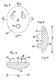
- FIGS. 1-4 show a patella protector 10 which comprises a thin wafer, with a bearing surface 12 and a bone-contacting surface 14.
- the first illustrated patella protector 10 also includes a plurality of mounting members 16, 18, 20.
- each mounting member comprises a peg that is sized and shaped to be received in a mating hole formed in the resected surface of the patella.
- the patella protector could have a single mounting member.
- the mounting members comprise pegs in the illustrated embodiment, the invention is not limited to use of such pegs unless expressly set forth in the claims.
- the patella protector 10 is generally provided as part of a system or surgical kit that would also include a patellar implant and a patellar trial. Generally, several sizes of the implant components and trials would be provided to accommodate the needs of the individual patient. Similarly, the system or surgical kit could also include several sizes of patella protectors as well. Typically, a patella protector corresponding in size and shape to each size and shape of implant and trial would be included in the kit.
- patellar protector 10, implant 22 and trial 24 are generally oval in shape in plan view.
- the patellar protector, implant and trial could have other shapes, such as an overall circular shape, for example.
- the present invention is not limited to any particular shape of any of the components of the system or kit unless expressly called for in the claims.
- Both the illustrated implant 22 and trial 24 have flat bone contacting surfaces 26, 28, opposite articulating surfaces 30, 32 and one or more mounting members 34, 36, 38, 40, 42, 44.
- the implant 22, trial 24 and patella protector 10 are intended to be separately mounted to a flat resected surface of the patella.
- the mounting members 16, 18, 20, 34, 36, 38, 40, 42, 44 of the implant, trial and patella protector are all similarly sized so that they may all be separately received in mating holes drilled into the resected patella.
- the mounting members 16, 18, 20, 34, 36, 38, 40, 42, 44 are received in holes in the patella and only the portions of the protector 10, implant 22 and trial 24 from the bone-contacting surfaces 14, 26, 28 to the bearing 12 and articulating surfaces 30, 32 extend beyond the resected surface of the patella.
- the portions of the implant 22 and trial 24 that extend beyond the resected surface of the patella have maximum thicknesses shown at t 1 and t 2 .
- the dimensions for t 1 and t 2 range from about 0.3 inches to about 0.45 inches.
- the corresponding trial 24 would have the same thickness.
- the patella protector 10 is much thinner, with a thickness shown at t 3 in FIG. 2 of about 0.04 - 0.08 inches (1-2 mm).
- the patella protector 10 when the patella protector 10 is mounted to the patella, a significant gap exists between the protector bearing surface 12 and the facing surface of the femur, a gap that decreases significantly when the protector 10 is removed and the implant 22 or trial 24 is mounted to the resected patella.
- the gap existing when the protector 10 is mounted to the patella is advantageous in improving the surgeon's ability to move the patella intraoperatively without unduly stressing the soft tissue connecting the patella to the femur and tibia, as described in more detail below.
- the illustrated oval patella protector 10, implant 22 and trial 24 have overall lengths and widths, shown at d 1 and d 2 , respectively, in FIGS. 2-3, 6-7 and 9-10.
- Typical dimensions for d 1 may range from about 1.26 inch to about 1.6 inch (32 mm to 41 mm); typical dimensions for d 2 may range from about 1 inch to about 1.4 inch (25.4 to 40.6 mm).
- a typical system or kit would include several sizes of protectors 10, implants 22 and trials 24 to accommodate the size of the patient's patella.
- the patella protector 10 can be made of a variety of materials. For example, surgical grade stainless steel could be used. Alternatively, a suitable plastic material could be used. Examples of suitable plastic materials include the acetal copolymer sold under the trade mark CELCON and polysulphone. Alternatively, a combination of materials could be used for the patella protector; for example, the bearing surface 12 could be made of a thin sheet of metal mounted on a plastic base. Preferably, the material is resistant to fracture and can be sterilized. The patella protector 10 could be intended for single use or could be intended to part reusable; the choice of material can be expected to depend at least in part on the intended useful life of the patella protector 10.
- the patella protector may be desirable to make out of a coloured material so that the protector can be quickly and easily seen and distinguished from the patient's native tissue; for example, the patella protector could be black, green or red in colour. It should be understood that the present invention is not limited to any particular material for the patella protector unless expressly called for in the claims.
- the patellar implant 22 and patellar trial 24 can be standard commercially available products. Suitable implants and trials are available from DePuy Orthopaedics, Inc., of Warsaw, Indiana. Commercially available implants 22 and trials 24 include products known as a three-peg oval dome patella, as shown in FIGS. 5-10. These implants 22 are typically made of ultrahigh molecular weight polyethylene. Patellar implants 22 and trials 24 are also available in a circular shape, and with a single mounting peg instead of the illustrated three mounting pegs.
- patellar implants are available that include an articulating surface made of a material having a low coefficient of friction mounted on a metal base; in such designs, the bone-contacting surface is on the metal base and the articulating surface is made of a material such as ultrahigh molecular weight polyethylene. It is expected that the present invention can be used with any type of patellar implant and trial.
- a typical surgical kit would also include other components to replace portions of the distal femur and proximal tibia.
- Such components are commercially available from DePuy Orthopaedics Inc of Warsaw, Indiana. Suitable examples include prosthetic implant components sold by DePuy under the trade mark PFC Sigma. Suitable trials and instrumentation for implanting these components are also available from DePuy Orthopaedics.
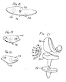
- FIG. 21 illustrates a prosthetic femoral implant 50, a prosthetic tibial tray 52, a tibial insert 54 and a patellar implant 22.
- the illustrated tibial component is a mobile bearing component, it should be understood that fixed bearing tibial components can be used as well.
- patella protector 10, trials 24 and implants 22 may be used in the surgical technique or method of the present invention.
- the surgeon can advantageously reduce the size of the incision made and can minimize soft tissue trauma.
- a longitudinal incision is made from the superior pole of the patella and over the medial edge of the patella to a point about one centimetre proximal to the medial margin of the tibial tubercle.
- the incision may be extended if necessary to achieve exposure or to relax severe skin tension during the procedure.
- the patella is the first bone resected in this method of performing total knee replacement.
- the knee is fully extended, and the patella is turned and held vertically.
- the patella 60 is resected and a template is selected that covers the resected patellar surface without overhang.
- a peg hole or holes are then drilled into the patella.
- An appropriately sized patellar trial, such as trial 24, is placed on the resected patella, with the trial pegs 40, 42, 44 received in the peg holes in the patella. Overall patellar thickness is then assessed. Once the surgeon is satisfied with the patellar trial, the trial is removed and replaced with the patellar protector 10 of the present invention.
- the pegs 16, 18, 20 are placed in the peg holes and the bone-contacting surface 14 is placed against the resected surface of the patella.
- the diameter of the pegs 16, 18, 20 is similar to the diameter of the peg holes (and similar to the diameters of the pegs 34, 36, 38, 40, 42, 44 of the implant 22 and trial 24) so that position of the protector 10 is maintained without additional support.
- the patella may then be subluxated into the lateral gutter to expose portions of the distal femur and proximal tibia (see FIG. 12).
- the patella may be subluxated medially to expose portions of the distal femur and proximal tibia (see FIG. 13). With the patella subluxated, it is turned at an angle substantially less than a 180-degree eversion; instead, the patella is turned at an angle on the order of 90 degrees or less, substantially decreasing stress to the soft tissue associated with the patella.
- any osteophytes of the lateral femoral condyle should be removed. Since osteophytes of the lateral condyle can measure as much as 10 mm, it is desirable to remove such osteophytes to decrease soft tissue tension when the patella is subluxated along the lateral aspect of the lateral femoral condyle and moved into the lateral gutter. Similarly, if the patella is to be subluxated medially, osteophytes of the medial femoral condyle should be removed.
- the proximal tibia is moved in the anteromedial direction toward the surgical opening. Simultaneously, the ligaments and tendons are protected to prevent undue stress during this movement of the proximal tibia. Movement of the tibia and tibial resection can be done with the knee in flexion.
- FIGS. 11-13 illustrate a knee in flexion diagrammatically.
- FIG. 11 illustrates the native patella 60 and its associated soft tissue 62 and its relationship to the patient's distal femur 64 and proximal tibia 66.
- FIGS. 12 and 13 illustrates the patella 60 after it has been resected and after a patella protector 10 has been mounted to the resected surface of the patella.
- FIG. 12 also illustrates a position (lateral) of the subluxated patella 60 that can be used in the method of the present invention.
- FIG. 13 illustrates the resected patella and patella protector subluxated medially.
- a 90-degree Hohman retractor and a straight Hohman retractor are used. Part of the 90-degree Hohman retractor may be placed against the lateral proximal tibia and part of the 90-degree retractor is placed against the bearing surface 12 of the patella protector 10. The end of the straight Hohman retractor is placed next to the posterior cruciate ligament on the proximal tibia.
- the surgeon then subluxates the tibia anteromedially, excising the anterior cruciate ligament and the roots of the posterior medial and lateral meniscus.
- the 90-degree Hohman retractor acts as a lever in this procedure, pivoting on the bearing surface 12 of the patella protector 10. After sufficient parts of the proximal tibia are exposed, the surgeon can then follow standard procedures in positioning a cutting block and resecting the tibial plateau.
- the TKR procedure can be less invasive. A smaller initial incision may be made, and the potential for trauma to the soft tissue associated with the patella is substantially reduced.
- FIGS. 14-17 illustrates a various embodiments of femoral condyle protectors 70A, 70B, 70C, 70D.
- the first illustrated femoral condyle protector 70A includes a plurality of flat bearing surfaces 72A, 74A, 76A, 78A, 80A, a plurality of flat bone-contacting surfaces 82A, 84A, 86A, 88A, 90A and a mounting member 92A.
- the illustrated mounting member 92A corresponds in size, shape and position with one mounting peg of a corresponding femoral trial and femoral implant.
- the first illustrated femoral protector 70A is sized and shaped to cover the entire resected surface of a single femoral condyle, to facilitate use of the protector 70A in a minimally invasive procedure.
- Alternative shapes are possible. For example, as shown in FIGS.
- a femoral condyle protector 70B, 70C could have fewer bearing surfaces 74B, 76B, 78B, 80B, 74C, 76C, 78C and bone-contacting surfaces 84B, 86B, 88B, 90B, 84C, 86C, 88C so that less than all of the resected distal femoral condyle is covered by a protector. It should be understood that other shapes are possible. It should be understood that a femoral protector could alternatively be shaped to cover all or substantially all of the resected surface of the distal femur. In addition, two femoral protectors 70A, 70B, 70C of any of the types illustrated in FIG.
- a femoral protector could cover all or some of the resected surfaces of both condyles of the distal femur.
- a femoral protector 70D could have two condylar portions 71, 73 joined by a bridge portion 75, all having both a plurality of bone-contacting surfaces 77 and a plurality of bearing surfaces 79.
- One or two mounting members 92D could also be provided.
- the femoral protector 70A, 70B, 70C, 70D can be made of the same material as the patella protector 10, and can be made to be thin, on the order of 1-2 mm.
- the resected distal femur would not be expected to have the inferior mechanical properties of the resected patella, such as any of the illustrated femoral protectors 70A, 70B, 70C, 70D could be useful in preventing damage (such as chipping or scratching) to the resected surfaces of the femur.
- the resected tibial plateau would not be expected to have the inferior mechanical properties of the resected patella.
- a tibial protector 94 as illustrated in FIG. 18, or a two-piece tibial protector as shown in FIGS. 19 and 20.
- the one-piece tibial protector 94 of FIG. 18 has a bone-contacting surface 96, a bearing surface 98 and a pair of mounting members 100, 102.
- the two-piece protector comprises a medial tibial protector 104, with a bone-contacting surface 106, a bearing surface 108 and a mounting member 110, and a complementary lateral tibial protector 112, with a bone-contacting surface 114, a bearing surface 116 and a mounting member 118.
- the illustrated bearing surfaces 98, 108, 116 are flat, and the thickness of each protector 96, 104, 112 is on the order of 1-2 mm. It should be understood that the shapes of the tibial protectors 96, 104, 112 are provided as examples only; other shapes may be provided, depending for example, on whether the procedure is a cruciate sacrificing procedure.
- the illustrated tibial protectors can be made of the same materials as described above for the patella protector.
Abstract
Description
- This invention relates generally to a surgical technique for total joint replacement with minimal trauma to tissue and to a device and surgical kit to be used in minimizing trauma to tissue.
- Total knee replacement (TKR) surgery and component systems for replacing compartments of a knee in total replacement surgery are well known. The long-term goals of TKR are to help relieve pain, improve joint function and provide a durable reconstruction with proper component and limb alignment. Typically, the surgery involves resecting the distal end of a femur so a prosthetic femoral implant component may be mounted to the femur. The prosthetic femoral implant component replaces the lateral condyle, medial condyle, and patellofemoral portions of the femur because one or more of these areas of the knee are diseased.
- In TKR surgery, the proximal end of the tibia is also resected so that a prosthetic tibial implant component may be mounted to the tibia to receive the lateral and medial condyles of the femoral component. The prosthetic tibial implant component may be comprised of a material having a low coefficient of friction to simulate the meniscus being replaced by the tibial component. Commonly, the prosthetic tibial implant component is two-piece, comprising a tibial tray to be mounted to the tibia and a low-friction bearing insert to be mounted to the tibial tray and to receive the condyles of the femoral implant component.
- In TKR surgery, a portion of the patella is also resected so that a prosthetic patellar implant component may be mounted to the patella. The prosthetic patellar implant component typically includes a material with a low coefficient of friction that moves along a portion of the prosthetic femoral implant component as the patient flexes and extends the leg. In some prosthetic patellar implant components, the entire implant is made of a low-friction material; in others, a low-friction bearing is mounted to a metal base.
- The mechanical properties of the resected patella are inferior. The force of a retractor pushing against the resected surface can be substantial, and may lead to damage or even fracture of the thin patella. In addition, some TKR patients are older and may have substantial inferior bone quality due to osteopenia. Therefore the resected patella is also susceptible to additional damage, for example, by a saw blade. The problems associated with the inferior mechanical properties of the resected patella are avoided in TKR procedures by performing the patellar resection after the femoral and tibial resections.
- However, the patella and its associated soft tissues cover substantial parts of the distal femur and proximal tibia. Accordingly, to expose the distal femur and proximal tibia, the patella is first everted laterally to expose the distal femur and proximal tibia. In everting the patella, it is turned inside out, about 180 degrees. The distal femur and proximal tibia are resected and prepared to receive the prosthetic femoral and tibial components. The patella is then resected after the femur and tibia have been resected.
- Because the patella is everted, or turned inside out, during TKR, the soft tissue envelope of the knee is disrupted and the soft tissue can be placed under substantial stress. The stress on this soft tissue can disrupt the quadriceps mechanism and traumatize the extensor mechanism of the knee. This stress and trauma can lead to post-operative pain and discomfort, and the time required for patient recovery can be extensive. In addition, violation of the suprapatellar pouch can lead to heterotopic ossification and arthrofibrosis.
- Accordingly, there is a need for a system and method for performing TKR surgery that achieves the long-term goals discussed above, but that also achieves the following short-term goals: minimize soft tissue trauma, minimize surgical morbidity and help speed patient recovery.
- The need for a system and method for performing TKR surgery with minimal disruption of the soft tissue envelope of the knee is met by the surgical method, surgical kit and bone protector of the present invention.
- In one aspect, the present invention provides a bone protector that can be used in the surgical method to cover and protect the resected patella. The bone protector comprises a bone-contacting surface and an opposite bearing surface. A mounting member is provided on the bone-contacting surface for temporarily mounting the bone protector to a surface of a bone. The bone protector has a thickness between the bone-contacting surface and the bearing surface. The bearing surface is substantially flat.
- In another aspect, the present invention provides a surgical kit for prosthetic implants for replacing portions of bones of a joint. The kit comprises a first prosthetic implant component, a first prosthetic trial component and a bone protector. The first prosthetic implant component has a bone-contacting surface and an articulating surface. The first prosthetic trial component also has a bone-contacting surface and an articulating surface. The bone protector has a bone-contacting surface and a bearing surface. The first prosthetic implant component, first prosthetic trial component and bone protector are all capable of being separately mounted to a portion of the same bone. The bearing surface of the bone protector has a different shape than the articulating surfaces of the prosthetic implant component and prosthetic trial component.
- In another aspect, the present invention provides a surgical kit for prosthetic implants for replacing portions of bones of a joint. The kit comprises a first prosthetic implant component, a first prosthetic trial component and a bone protector. The first prosthetic implant component has a bone-contacting surface, an articulating surface, and a thickness between the bone-contacting surface and the articulating surface. The first prosthetic trial component has a bone-contacting surface, an articulating surface, and a thickness between the bone-contacting surface and the articulating surface. The bone protector has a bone-contacting surface, a bearing surface, and a thickness between the bone-contacting surface and the bearing surface. The first prosthetic implant component, first prosthetic trial component and bone protector are all capable of being separately mounted to a portion of the same bone. The thickness of the bone protector is less than the thickness of the first prosthetic implant component and less than the thickness of the first prosthetic trial component.
- The apparatus provided by the present invention can be used in a surgical method of performing total knee arthroplasty. The method involves resecting and covering a portion of the patella before resecting a portion of the distal femur and proximal tibia. In this method, the patella is subluxated rather than everted, so soft tissue trauma is minimized. In addition, the resected patella is protected from damage from the subluxation.
- Embodiments of the invention will now be described by way of example with reference to the accompanying drawings, in which:
- FIG. 1 is perspective view of a patella protector incorporating the principles of the present invention, showing the bone-contacting surface and mounting members of the patella protector;
- FIG. 2 is a side elevation of the patella protector of FIG. 1;
- FIG. 3 is a bottom plan view of the patella protector of FIGS. 1-2;
- FIG. 4 is a top plan view of the patella protector of FIGS. 1-3;
- FIG. 5 is a bottom plan view of a prosthetic patellar implant that can be used with the patella protector of FIGS. 1-4;
- FIG. 6 is a cross-section of the prosthetic patellar implant of FIG. 5, taken along line 6-6 of FIG. 5;
- FIG. 7 is a cross-section of the prosthetic patellar implant of FIG. 5, taken along line 7-7 of FIG. 5;
- FIG. 8 is a bottom plan view of a patellar trial that can be used with the patella protector of FIGS. 1-4 and implant of FIGS. 5-8;
- FIG. 9 is a cross-section of the patellar trial of FIG. 8, taken along line 9-9 of FIG. 8;
- FIG. 10 is a cross-section of the patellar trial of FIG. 8, taken along line 10-10 of FIG. 8;
- FIG. 11 is a diagrammatic representation of an anterior view of a knee in flexion;
- FIG. 12 is a diagrammatic representation of an anterior view of a knee in flexion with the patella resected, a patella protector mounted to the patella, and with the patella subluxated laterally;
- FIG. 13 is a diagrammatic representation similar to FIG. 12, but with the patella subluxated medially;
- FIG. 14 is a perspective view of one embodiment of a femoral condyle protector;
- FIG. 15 is perspective view of another embodiment of a femoral condyle protector;
- FIG. 16 is a perspective view of a third embodiment of a femoral condyle protector;
- FIG. 17 is a perspective view of a fourth embodiment of a femoral condyle protector;
- FIG. 18 is a perspective view of a tibial plateau protector;
- FIG. 19 is a perspective view of a medial tibial plateau protector;
- FIG. 20 is a perspective view of a lateral tibial plateau protector; and
- FIG. 21 is a perspective view of a femoral implant, patellar implant, tibial insert and tibial tray.
-
- Bone protectors and a prosthetic implant system incorporating the principles of the present invention are illustrated in the accompanying drawings. The first illustrated bone protector is a patella protector. The principles of the present invention can also be applied to other bones, such as the femur and tibia, and embodiments of bone protectors for use in TKR are also illustrated in the accompanying drawings. It should be understood that the principles of the present invention can be applied to the replacement of the bones of other joints as well, and that the invention is not limited to any particular bone unless expressly set forth in the claims.
- Referring to the drawings, FIGS. 1-4 show a
patella protector 10 which comprises a thin wafer, with a bearingsurface 12 and a bone-contactingsurface 14. The firstillustrated patella protector 10 also includes a plurality of mountingmembers - The
patella protector 10 is generally provided as part of a system or surgical kit that would also include a patellar implant and a patellar trial. Generally, several sizes of the implant components and trials would be provided to accommodate the needs of the individual patient. Similarly, the system or surgical kit could also include several sizes of patella protectors as well. Typically, a patella protector corresponding in size and shape to each size and shape of implant and trial would be included in the kit. - An example of a patellar implant is shown at 22 in FIGS.5-7, and an example of a patellar trial is shown at 24 in FIGS. 8-10. In the illustrated embodiments, the
patellar protector 10,implant 22 andtrial 24 are generally oval in shape in plan view. However, it should be understood that the patellar protector, implant and trial could have other shapes, such as an overall circular shape, for example. The present invention is not limited to any particular shape of any of the components of the system or kit unless expressly called for in the claims. - Both the illustrated
implant 22 andtrial 24 have flatbone contacting surfaces surfaces members implant 22,trial 24 andpatella protector 10 are intended to be separately mounted to a flat resected surface of the patella. The mountingmembers members protector 10,implant 22 andtrial 24 from the bone-contactingsurfaces bearing 12 and articulatingsurfaces - As shown in FIGS. 6 and 9, the portions of the
implant 22 andtrial 24 that extend beyond the resected surface of the patella have maximum thicknesses shown at t1 and t2. Typically, the dimensions for t1 and t2 range from about 0.3 inches to about 0.45 inches. Generally, for each size ofimplant 22, the correspondingtrial 24 would have the same thickness. In contrast, thepatella protector 10 is much thinner, with a thickness shown at t3 in FIG. 2 of about 0.04 - 0.08 inches (1-2 mm). Thus, when thepatella protector 10 is mounted to the patella, a significant gap exists between theprotector bearing surface 12 and the facing surface of the femur, a gap that decreases significantly when theprotector 10 is removed and theimplant 22 ortrial 24 is mounted to the resected patella. The gap existing when theprotector 10 is mounted to the patella is advantageous in improving the surgeon's ability to move the patella intraoperatively without unduly stressing the soft tissue connecting the patella to the femur and tibia, as described in more detail below. - The illustrated
oval patella protector 10,implant 22 andtrial 24 have overall lengths and widths, shown at d1 and d2, respectively, in FIGS. 2-3, 6-7 and 9-10. Typical dimensions for d1 may range from about 1.26 inch to about 1.6 inch (32 mm to 41 mm); typical dimensions for d2 may range from about 1 inch to about 1.4 inch (25.4 to 40.6 mm). A typical system or kit would include several sizes ofprotectors 10,implants 22 andtrials 24 to accommodate the size of the patient's patella. - The
patella protector 10 can be made of a variety of materials. For example, surgical grade stainless steel could be used. Alternatively, a suitable plastic material could be used. Examples of suitable plastic materials include the acetal copolymer sold under the trade mark CELCON and polysulphone. Alternatively, a combination of materials could be used for the patella protector; for example, the bearingsurface 12 could be made of a thin sheet of metal mounted on a plastic base. Preferably, the material is resistant to fracture and can be sterilized. Thepatella protector 10 could be intended for single use or could be intended to part reusable; the choice of material can be expected to depend at least in part on the intended useful life of thepatella protector 10. It may be desirable to make the patella protector out of a coloured material so that the protector can be quickly and easily seen and distinguished from the patient's native tissue; for example, the patella protector could be black, green or red in colour. It should be understood that the present invention is not limited to any particular material for the patella protector unless expressly called for in the claims. - The
patellar implant 22 andpatellar trial 24 can be standard commercially available products. Suitable implants and trials are available from DePuy Orthopaedics, Inc., of Warsaw, Indiana. Commerciallyavailable implants 22 andtrials 24 include products known as a three-peg oval dome patella, as shown in FIGS. 5-10. Theseimplants 22 are typically made of ultrahigh molecular weight polyethylene.Patellar implants 22 andtrials 24 are also available in a circular shape, and with a single mounting peg instead of the illustrated three mounting pegs. In addition, patellar implants are available that include an articulating surface made of a material having a low coefficient of friction mounted on a metal base; in such designs, the bone-contacting surface is on the metal base and the articulating surface is made of a material such as ultrahigh molecular weight polyethylene. It is expected that the present invention can be used with any type of patellar implant and trial. - A typical surgical kit would also include other components to replace portions of the distal femur and proximal tibia. Such components are commercially available from DePuy Orthopaedics Inc of Warsaw, Indiana. Suitable examples include prosthetic implant components sold by DePuy under the trade mark PFC Sigma. Suitable trials and instrumentation for implanting these components are also available from DePuy Orthopaedics. FIG. 21 illustrates a prosthetic
femoral implant 50, aprosthetic tibial tray 52, a tibial insert 54 and apatellar implant 22. Although the illustrated tibial component is a mobile bearing component, it should be understood that fixed bearing tibial components can be used as well. - The above-described
patella protector 10,trials 24 andimplants 22 may be used in the surgical technique or method of the present invention. Using the components of the present invention, the surgeon can advantageously reduce the size of the incision made and can minimize soft tissue trauma. - Initially, a longitudinal incision is made from the superior pole of the patella and over the medial edge of the patella to a point about one centimetre proximal to the medial margin of the tibial tubercle. The incision may be extended if necessary to achieve exposure or to relax severe skin tension during the procedure.
- The patella is the first bone resected in this method of performing total knee replacement. The knee is fully extended, and the patella is turned and held vertically. The
patella 60 is resected and a template is selected that covers the resected patellar surface without overhang. A peg hole or holes are then drilled into the patella. An appropriately sized patellar trial, such astrial 24, is placed on the resected patella, with the trial pegs 40, 42, 44 received in the peg holes in the patella. Overall patellar thickness is then assessed. Once the surgeon is satisfied with the patellar trial, the trial is removed and replaced with thepatellar protector 10 of the present invention. Thepegs surface 14 is placed against the resected surface of the patella. The diameter of thepegs pegs implant 22 and trial 24) so that position of theprotector 10 is maintained without additional support. The patella may then be subluxated into the lateral gutter to expose portions of the distal femur and proximal tibia (see FIG. 12). Alternatively, the patella may be subluxated medially to expose portions of the distal femur and proximal tibia (see FIG. 13). With the patella subluxated, it is turned at an angle substantially less than a 180-degree eversion; instead, the patella is turned at an angle on the order of 90 degrees or less, substantially decreasing stress to the soft tissue associated with the patella. - Before subluxating the patella laterally, any osteophytes of the lateral femoral condyle should be removed. Since osteophytes of the lateral condyle can measure as much as 10 mm, it is desirable to remove such osteophytes to decrease soft tissue tension when the patella is subluxated along the lateral aspect of the lateral femoral condyle and moved into the lateral gutter. Similarly, if the patella is to be subluxated medially, osteophytes of the medial femoral condyle should be removed.
- To expose the proximal tibia sufficiently for proper positioning of the cutting block, the proximal tibia is moved in the anteromedial direction toward the surgical opening. Simultaneously, the ligaments and tendons are protected to prevent undue stress during this movement of the proximal tibia. Movement of the tibia and tibial resection can be done with the knee in flexion.
- FIGS. 11-13 illustrate a knee in flexion diagrammatically. FIG. 11 illustrates the
native patella 60 and its associatedsoft tissue 62 and its relationship to the patient'sdistal femur 64 andproximal tibia 66. FIGS. 12 and 13 illustrates thepatella 60 after it has been resected and after apatella protector 10 has been mounted to the resected surface of the patella. FIG. 12 also illustrates a position (lateral) of thesubluxated patella 60 that can be used in the method of the present invention. FIG. 13 illustrates the resected patella and patella protector subluxated medially. - To move the proximal tibia in the anteromedial direction, force can be applied to the tibia from the posterolateral direction while protecting the patella and soft tissues from injury. To accomplish this combination of movement and protection, a 90-degree Hohman retractor and a straight Hohman retractor are used. Part of the 90-degree Hohman retractor may be placed against the lateral proximal tibia and part of the 90-degree retractor is placed against the bearing
surface 12 of thepatella protector 10. The end of the straight Hohman retractor is placed next to the posterior cruciate ligament on the proximal tibia. The surgeon then subluxates the tibia anteromedially, excising the anterior cruciate ligament and the roots of the posterior medial and lateral meniscus. The 90-degree Hohman retractor acts as a lever in this procedure, pivoting on the bearingsurface 12 of thepatella protector 10. After sufficient parts of the proximal tibia are exposed, the surgeon can then follow standard procedures in positioning a cutting block and resecting the tibial plateau. - More details of the surgical technique are provided in "PFC Sigma Knee System with Specialist mini Instruments", published in 2004 by DePuy Orthopaedics, Inc. of Warsaw, Indiana, publication no. 0612-57-500.
- It will be appreciated that with the surgical technique of the present invention, the TKR procedure can be less invasive. A smaller initial incision may be made, and the potential for trauma to the soft tissue associated with the patella is substantially reduced.
- It will be appreciated by those skilled in the art that the principles of the present invention can be applied to the protection of other bones of the knee joint, and to the bones of other joints of the body as well. For example, it may be desirable to provide a tibial protector or a femoral condyle protector. FIGS. 14-17 illustrates a various embodiments of
femoral condyle protectors femoral condyle protector 70A includes a plurality of flat bearing surfaces 72A, 74A, 76A, 78A, 80A, a plurality of flat bone-contactingsurfaces member 92A. The illustrated mountingmember 92A corresponds in size, shape and position with one mounting peg of a corresponding femoral trial and femoral implant. The first illustratedfemoral protector 70A is sized and shaped to cover the entire resected surface of a single femoral condyle, to facilitate use of theprotector 70A in a minimally invasive procedure. Alternative shapes are possible. For example, as shown in FIGS. 15 and 16, afemoral condyle protector 70B, 70C could have fewer bearing surfaces 74B, 76B, 78B, 80B, 74C, 76C, 78C and bone-contactingsurfaces femoral protectors femoral protector 70D could have two condylar portions 71, 73 joined by abridge portion 75, all having both a plurality of bone-contactingsurfaces 77 and a plurality of bearing surfaces 79. One or two mountingmembers 92D could also be provided. Thefemoral protector patella protector 10, and can be made to be thin, on the order of 1-2 mm. Although the resected distal femur would not be expected to have the inferior mechanical properties of the resected patella, such as any of the illustratedfemoral protectors - Similarly, the resected tibial plateau would not be expected to have the inferior mechanical properties of the resected patella. However, it may be desirable to provide a
tibial protector 94 as illustrated in FIG. 18, or a two-piece tibial protector as shown in FIGS. 19 and 20. The one-piecetibial protector 94 of FIG. 18 has a bone-contactingsurface 96, a bearingsurface 98 and a pair of mountingmembers 100, 102. The two-piece protector comprises amedial tibial protector 104, with a bone-contactingsurface 106, a bearingsurface 108 and a mounting member 110, and a complementary lateraltibial protector 112, with a bone-contactingsurface 114, a bearingsurface 116 and a mountingmember 118. The illustrated bearing surfaces 98, 108, 116 are flat, and the thickness of eachprotector tibial protectors - Although the illustrated embodiments all relate to protection of resected surfaces of the bones of the knee joint, it should be appreciated that the principles of the present invention can be applied to other joints as well. For example, appropriately sized and shaped protectors could be provided for the hip joint, shoulder joint, ankle joint, and elbow joint.
Claims (12)
- A surgical kit for prosthetic implants for replacing portions of bones of a joint, the kit comprising:wherein the first prosthetic implant component, first prosthetic trial component and bone protector are all capable of being separately mounted to a portion of the same bone; anda first prosthetic implant component having a bone-contacting surface and an articulating surface;a first prosthetic trial component having a bone-contacting surface and an articulating surface;a bone protector having a bone-contacting surface and a bearing surface;
wherein the bearing surface of the bone protector has a different shape than the articulating surfaces of the prosthetic implant component and prosthetic trial component. - The surgical kit of claim 1 wherein the articulating surfaces are curved and the bearing surface is flat.
- The surgical kit of claim 1 wherein the prosthetic implant component comprises a patellar implant.
- The surgical kit of claim 1 further comprising a second prosthetic implant component having a bone-contacting surface and an articulating surface, wherein the articulating surface of the second prosthetic implant component is shaped to articulate against the articulating surface of the first prosthetic implant component.
- A surgical kit for prosthetic implants for replacing portions of bones of a joint, the kit comprising:wherein the first prosthetic implant component, first prosthetic trial component and bone protector are all capable of being separately mounted to a portion of the same bone; anda first prosthetic implant component having a bone-contacting surface, an articulating surface, and a thickness between the bone-contacting surface and the articulating surface;a first prosthetic trial component having a bone-contacting surface, an articulating surface, and a thickness between the bone-contacting surface and the articulating surface;a bone protector having a bone-contacting surface, a bearing surface, and a thickness between the bone-contacting surface and the bearing surface;
wherein the thickness of the bone protector is less than the thickness of the first prosthetic implant component and less than the thickness of the first prosthetic trial component. - The system of claim 5 wherein:the first prosthetic implant component has a length and a width, the first prosthetic trial component has a length and a width and the bone protector has a length and a widththe lengths of the first prosthetic implant component, first prosthetic trial component and bone protector are substantially the same; andthe widths of the first prosthetic implant component, first orthopaedic trial component and bone protector are substantially the same.
- The kit of claim 6 wherein the thickness of the bone protector is about 1-2 mm.
- The kit of claim 5 wherein the bone protector, first prosthetic implant component and first prosthetic trial component each includes a mounting member extending outward from the bone-contacting surface.
- The system of claim 5 wherein:the first prosthetic implant component comprises a prosthetic patellar implant;the first prosthetic trial component comprises a prosthetic patellar trial; andthe bone protector comprises a patellar protector.
- The kit of claim 9 further comprising a prosthetic femoral implant and a prosthetic tibial implant.
- A surgical kit for prosthetic implants for replacing portions of the femur and patella of the knee joint, the kit comprising:wherein the prosthetic patella implant component, prosthetic patella trial component and patella protector are all capable of being separately mounted to a portion of the patella; anda prosthetic patella implant component having a bone-contacting surface, a curved articulating surface and a thickness between the bone-contacting surface and the articulating surface;a prosthetic patella trial component having a bone-contacting surface, a curved articulating surface and a thickness between the bone-contacting surface and the articulating surface;a patella protector having a bone-contacting surface, a flat bearing surface and a thickness between the bone-contacting surface and the articulating surface;
wherein the thickness of the patella protector is less than the thickness of the prosthetic patella trial component and less than the thickness of the prosthetic patella implant. - A bone protector comprising:wherein the bone protector has a thickness between the bone-contacting surface and the bearing surface; anda bone-contacting surface and an opposite bearing surface; anda mounting member on the bone-contacting surface for temporarily mounting the bone protector to a surface of a bone;
wherein the bearing surface is substantially flat.
Applications Claiming Priority (2)
| Application Number | Priority Date | Filing Date | Title |
|---|---|---|---|
| US53866104P | 2004-01-23 | 2004-01-23 | |
| US538661P | 2004-01-23 |
Publications (2)
| Publication Number | Publication Date |
|---|---|
| EP1557144A1 true EP1557144A1 (en) | 2005-07-27 |
| EP1557144B1 EP1557144B1 (en) | 2007-05-09 |
Family
ID=34633031
Family Applications (1)
| Application Number | Title | Priority Date | Filing Date |
|---|---|---|---|
| EP05250109A Active EP1557144B1 (en) | 2004-01-23 | 2005-01-11 | Bone protector kit |
Country Status (6)
| Country | Link |
|---|---|
| US (3) | US7749276B2 (en) |
| EP (1) | EP1557144B1 (en) |
| JP (1) | JP4498936B2 (en) |
| AT (1) | ATE361724T1 (en) |
| AU (1) | AU2005200104B2 (en) |
| DE (1) | DE602005001057T2 (en) |
Cited By (9)
| Publication number | Priority date | Publication date | Assignee | Title |
|---|---|---|---|---|
| EP1905395A1 (en) | 2006-09-29 | 2008-04-02 | DePuy Products, Inc. | Osteotomy protective cover |
| EP2140836A1 (en) * | 2008-06-30 | 2010-01-06 | DePuy Products, Inc. | Patella Component |
| US7972383B2 (en) | 2008-06-30 | 2011-07-05 | Depuy Products, Inc. | Implantable patella component having a thickened superior edge |
| US8142510B2 (en) | 2007-03-30 | 2012-03-27 | Depuy Products, Inc. | Mobile bearing assembly having a non-planar interface |
| US8147558B2 (en) | 2007-03-30 | 2012-04-03 | Depuy Products, Inc. | Mobile bearing assembly having multiple articulation interfaces |
| US8147557B2 (en) | 2007-03-30 | 2012-04-03 | Depuy Products, Inc. | Mobile bearing insert having offset dwell point |
| US8328874B2 (en) | 2007-03-30 | 2012-12-11 | Depuy Products, Inc. | Mobile bearing assembly |
| US8764841B2 (en) | 2007-03-30 | 2014-07-01 | DePuy Synthes Products, LLC | Mobile bearing assembly having a closed track |
| US8834574B2 (en) | 2010-12-07 | 2014-09-16 | Zimmer, Inc. | Prosthetic patella |
Families Citing this family (47)
| Publication number | Priority date | Publication date | Assignee | Title |
|---|---|---|---|---|
| FR2896404B1 (en) * | 2006-01-24 | 2008-02-29 | Tornier Sas | SURGICAL INSTRUMENTATION ASSEMBLY FOR POSTING AN ANKLE PROSTHESIS |
| US7780735B2 (en) * | 2006-09-29 | 2010-08-24 | Shank Cheryl A | Method of protecting a knee prosthesis during intra-operative implantation |
| US8328873B2 (en) | 2007-01-10 | 2012-12-11 | Biomet Manufacturing Corp. | Knee joint prosthesis system and method for implantation |
| US8562616B2 (en) | 2007-10-10 | 2013-10-22 | Biomet Manufacturing, Llc | Knee joint prosthesis system and method for implantation |
| US8163028B2 (en) | 2007-01-10 | 2012-04-24 | Biomet Manufacturing Corp. | Knee joint prosthesis system and method for implantation |
| US8157869B2 (en) | 2007-01-10 | 2012-04-17 | Biomet Manufacturing Corp. | Knee joint prosthesis system and method for implantation |
| US8187280B2 (en) | 2007-10-10 | 2012-05-29 | Biomet Manufacturing Corp. | Knee joint prosthesis system and method for implantation |
| EP2178468B1 (en) | 2007-08-01 | 2016-06-22 | Jeffrey Halbrecht | System for patella tendon realignment |
| US20100131069A1 (en) * | 2007-08-01 | 2010-05-27 | Jeffrey Halbrecht | Method and system for patella tendon realignment |
| US8088163B1 (en) | 2008-02-06 | 2012-01-03 | Kleiner Jeffrey B | Tools and methods for spinal fusion |
| GB0812631D0 (en) * | 2008-07-10 | 2008-08-20 | Imp Innovations Ltd | Modular knee implants |
| US9907597B2 (en) | 2008-08-12 | 2018-03-06 | Charles E. Kollmer | Bone compression system and associated methods |
| US9247963B2 (en) * | 2008-08-12 | 2016-02-02 | Charles Kollmer | Bone compression device and methods |
| US8257357B2 (en) * | 2008-09-23 | 2012-09-04 | Edwin Burton Hatch | Combination of a motor driven oscillating orthopedic reshaping and resurfacing tool and a surface-matching sheet metal prosthesis |
| US8187283B2 (en) * | 2008-09-30 | 2012-05-29 | Depuy Products, Inc. | Reusable orthopaedic instrument having drain holes |
| USD853560S1 (en) | 2008-10-09 | 2019-07-09 | Nuvasive, Inc. | Spinal implant insertion device |
| US8864654B2 (en) | 2010-04-20 | 2014-10-21 | Jeffrey B. Kleiner | Method and apparatus for performing retro peritoneal dissection |
| US8366748B2 (en) | 2008-12-05 | 2013-02-05 | Kleiner Jeffrey | Apparatus and method of spinal implant and fusion |
| US9717403B2 (en) | 2008-12-05 | 2017-08-01 | Jeffrey B. Kleiner | Method and apparatus for performing retro peritoneal dissection |
| USD656610S1 (en) | 2009-02-06 | 2012-03-27 | Kleiner Jeffrey B | Spinal distraction instrument |
| US9247943B1 (en) | 2009-02-06 | 2016-02-02 | Kleiner Intellectual Property, Llc | Devices and methods for preparing an intervertebral workspace |
| US9861408B2 (en) | 2009-08-27 | 2018-01-09 | The Foundry, Llc | Method and apparatus for treating canine cruciate ligament disease |
| US9278004B2 (en) | 2009-08-27 | 2016-03-08 | Cotera, Inc. | Method and apparatus for altering biomechanics of the articular joints |
| ES2477581T3 (en) | 2009-08-27 | 2014-07-17 | Cotera, Inc. | Apparatus for redistribution of forces in joint joints |
| US9668868B2 (en) | 2009-08-27 | 2017-06-06 | Cotera, Inc. | Apparatus and methods for treatment of patellofemoral conditions |
| US10349980B2 (en) | 2009-08-27 | 2019-07-16 | The Foundry, Llc | Method and apparatus for altering biomechanics of the shoulder |
| US8685031B2 (en) | 2009-09-18 | 2014-04-01 | Spinal Surgical Strategies, Llc | Bone graft delivery system |
| US10973656B2 (en) | 2009-09-18 | 2021-04-13 | Spinal Surgical Strategies, Inc. | Bone graft delivery system and method for using same |
| US20170238984A1 (en) | 2009-09-18 | 2017-08-24 | Spinal Surgical Strategies, Llc | Bone graft delivery device with positioning handle |
| US8906028B2 (en) | 2009-09-18 | 2014-12-09 | Spinal Surgical Strategies, Llc | Bone graft delivery device and method of using the same |
| USD723682S1 (en) | 2013-05-03 | 2015-03-03 | Spinal Surgical Strategies, Llc | Bone graft delivery tool |
| US9173694B2 (en) | 2009-09-18 | 2015-11-03 | Spinal Surgical Strategies, Llc | Fusion cage with combined biological delivery system |
| USD750249S1 (en) | 2014-10-20 | 2016-02-23 | Spinal Surgical Strategies, Llc | Expandable fusion cage |
| US10245159B1 (en) | 2009-09-18 | 2019-04-02 | Spinal Surgical Strategies, Llc | Bone graft delivery system and method for using same |
| US9629729B2 (en) | 2009-09-18 | 2017-04-25 | Spinal Surgical Strategies, Llc | Biological delivery system with adaptable fusion cage interface |
| US9186193B2 (en) | 2009-09-18 | 2015-11-17 | Spinal Surgical Strategies, Llc | Fusion cage with combined biological delivery system |
| US9060877B2 (en) | 2009-09-18 | 2015-06-23 | Spinal Surgical Strategies, Llc | Fusion cage with combined biological delivery system |
| US9468466B1 (en) | 2012-08-24 | 2016-10-18 | Cotera, Inc. | Method and apparatus for altering biomechanics of the spine |
| US10130480B2 (en) | 2013-03-13 | 2018-11-20 | Howmedica Osteonics Corp. | Modular patella trials |
| US9289306B2 (en) | 2013-03-15 | 2016-03-22 | Catalyst Orthopaedics Llc | Humeral arthroplasty |
| US9655727B2 (en) | 2013-12-12 | 2017-05-23 | Stryker Corporation | Extended patellofemoral |
| JP2015205134A (en) * | 2014-04-23 | 2015-11-19 | 株式会社 ウミヒラ | Levator |
| US10828082B2 (en) | 2015-02-06 | 2020-11-10 | Steven D. Colquhoun | Electrocautery device |
| CN104799979B (en) * | 2015-05-11 | 2017-01-25 | 北京爱康宜诚医疗器材股份有限公司 | Patellar prosthesis |
| USD797290S1 (en) | 2015-10-19 | 2017-09-12 | Spinal Surgical Strategies, Llc | Bone graft delivery tool |
| US10893948B2 (en) | 2017-11-02 | 2021-01-19 | Howmedica Osteonics Corp. | Rotary arc patella articulating geometry |
| US11896476B2 (en) | 2020-01-02 | 2024-02-13 | Zkr Orthopedics, Inc. | Patella tendon realignment implant with changeable shape |
Citations (3)
| Publication number | Priority date | Publication date | Assignee | Title |
|---|---|---|---|---|
| FR2699068A1 (en) * | 1992-12-14 | 1994-06-17 | Laboureau Jacques Philippe | Ancillary equipment for patellofemoral prosthesis. |
| FR2737848A1 (en) * | 1995-08-16 | 1997-02-21 | Lanternier Hubert | Instrument set for fitting patellar prosthesis |
| US6589248B1 (en) * | 2002-01-29 | 2003-07-08 | Joe L. Hughes | Patellar alignment device |
Family Cites Families (33)
| Publication number | Priority date | Publication date | Assignee | Title |
|---|---|---|---|---|
| US3806961A (en) * | 1972-02-16 | 1974-04-30 | Sulzer Ag | Phosthetic patella implant |
| US3878566A (en) * | 1974-05-08 | 1975-04-22 | Richards Mfg Co | Patello-femoral prosthesis |
| US3927423A (en) * | 1974-06-07 | 1975-12-23 | Alfred B Swanson | Patellar implant and method |
| US3964106A (en) * | 1975-03-03 | 1976-06-22 | Physical Systems, Inc. | Three-part total knee prosthesis |
| US4240162A (en) * | 1977-12-07 | 1980-12-23 | National Research Development Corporation | Endoprosthetic patellar device |
| US4285070A (en) * | 1978-06-05 | 1981-08-25 | Minnesota Mining And Manufacturing Company | Prosthetic device |
| US4207627A (en) * | 1979-01-18 | 1980-06-17 | Cloutier Jean Marie | Knee prosthesis |
| US4888021A (en) * | 1988-02-02 | 1989-12-19 | Joint Medical Products Corporation | Knee and patellar prosthesis |
| US4944756A (en) * | 1988-02-03 | 1990-07-31 | Pfizer Hospital Products Group | Prosthetic knee joint with improved patellar component tracking |
| US4979957A (en) * | 1989-09-11 | 1990-12-25 | Zimmer, Inc. | Textured prosthetic implant |
| US5197986A (en) * | 1990-04-11 | 1993-03-30 | Mikhail Michael W E | Recessed patellar prosthesis |
| US5236462A (en) * | 1991-04-23 | 1993-08-17 | Mikhail Michael W E | Metal-backed patellar prosthesis |
| CH685369A5 (en) * | 1991-07-05 | 1995-06-30 | Sulzer Ag | Patella prosthesis. |
| US5133758A (en) * | 1991-09-16 | 1992-07-28 | Research And Education Institute, Inc. Harbor-Ucla Medical Center | Total knee endoprosthesis with fixed flexion-extension axis of rotation |
| US5470354A (en) * | 1991-11-12 | 1995-11-28 | Biomet Inc. | Force sensing apparatus and method for orthopaedic joint reconstruction |
| US5480443A (en) * | 1992-01-31 | 1996-01-02 | Elias; Sarmed G. | Artifical implant component and method for securing same |
| US5609642A (en) * | 1995-02-15 | 1997-03-11 | Smith & Nephew Richards Inc. | Tibial trial prosthesis and bone preparation system |
| US5593450A (en) | 1995-02-27 | 1997-01-14 | Johnson & Johnson Professional, Inc. | Oval domed shaped patella prosthesis |
| JP3121262B2 (en) * | 1996-04-17 | 2000-12-25 | 良生 古賀 | Tibial trial jig for total knee arthroplasty |
| US5702465A (en) * | 1996-05-13 | 1997-12-30 | Sulzer Orthopedics Inc. | Patella prosthesis having rotational and translational freedom |
| JPH09322903A (en) * | 1996-06-05 | 1997-12-16 | Ikufumi Yamada | Bone fixing screw member turnable from both ends |
| US5702467A (en) * | 1996-06-12 | 1997-12-30 | Johnson & Johnson Professional, Inc. | Patellar resurfacing component |
| US5855601A (en) * | 1996-06-21 | 1999-01-05 | The Trustees Of Columbia University In The City Of New York | Artificial heart valve and method and device for implanting the same |
| US5871540A (en) * | 1996-07-30 | 1999-02-16 | Osteonics Corp. | Patellar implant component and method |
| US6068648A (en) * | 1998-01-26 | 2000-05-30 | Orthodyne, Inc. | Tissue anchoring system and method |
| ATE286692T1 (en) * | 1998-04-07 | 2005-01-15 | Macropore Inc | MEMBRANE WITH A CORRUPTED SURFACE FOR GUIDING THE FABRIC |
| US6616696B1 (en) | 1998-09-04 | 2003-09-09 | Alan C. Merchant | Modular knee replacement system |
| JP4278018B2 (en) * | 1999-11-19 | 2009-06-10 | 直秀 富田 | Knee joint unloading device |
| US6702821B2 (en) * | 2000-01-14 | 2004-03-09 | The Bonutti 2003 Trust A | Instrumentation for minimally invasive joint replacement and methods for using same |
| US6709460B2 (en) | 2000-03-21 | 2004-03-23 | Alan C. Merchant | Patellar bearing implant |
| US6478799B1 (en) * | 2000-06-29 | 2002-11-12 | Richard V. Williamson | Instruments and methods for use in performing knee surgery |
| US6296646B1 (en) * | 2000-06-29 | 2001-10-02 | Richard V. Williamson | Instruments and methods for use in performing knee surgery |
| US6599248B1 (en) * | 2001-03-20 | 2003-07-29 | Aloka | Method and apparatus for ultrasound diagnostic imaging |
-
2005
- 2005-01-11 AU AU2005200104A patent/AU2005200104B2/en active Active
- 2005-01-11 AT AT05250109T patent/ATE361724T1/en not_active IP Right Cessation
- 2005-01-11 DE DE602005001057T patent/DE602005001057T2/en active Active
- 2005-01-11 EP EP05250109A patent/EP1557144B1/en active Active
- 2005-01-21 US US11/039,978 patent/US7749276B2/en active Active
- 2005-01-21 JP JP2005014537A patent/JP4498936B2/en not_active Expired - Fee Related
-
2009
- 2009-12-18 US US12/641,356 patent/US8133233B2/en not_active Expired - Fee Related
-
2012
- 2012-02-03 US US13/365,563 patent/US20120136451A1/en not_active Abandoned
Patent Citations (3)
| Publication number | Priority date | Publication date | Assignee | Title |
|---|---|---|---|---|
| FR2699068A1 (en) * | 1992-12-14 | 1994-06-17 | Laboureau Jacques Philippe | Ancillary equipment for patellofemoral prosthesis. |
| FR2737848A1 (en) * | 1995-08-16 | 1997-02-21 | Lanternier Hubert | Instrument set for fitting patellar prosthesis |
| US6589248B1 (en) * | 2002-01-29 | 2003-07-08 | Joe L. Hughes | Patellar alignment device |
Cited By (16)
| Publication number | Priority date | Publication date | Assignee | Title |
|---|---|---|---|---|
| EP1905395A1 (en) | 2006-09-29 | 2008-04-02 | DePuy Products, Inc. | Osteotomy protective cover |
| US10363146B2 (en) | 2006-09-29 | 2019-07-30 | DePuy Synthes Products, Inc. | Osteotomy protective cover |
| US9925065B2 (en) | 2006-09-29 | 2018-03-27 | DePuy Synthes Products, Inc. | Method of using an osteotomy protective cover |
| US8821496B2 (en) | 2006-09-29 | 2014-09-02 | DePuy Synthes Products, LLC | Osteotomy protective cover |
| US8328874B2 (en) | 2007-03-30 | 2012-12-11 | Depuy Products, Inc. | Mobile bearing assembly |
| US8142510B2 (en) | 2007-03-30 | 2012-03-27 | Depuy Products, Inc. | Mobile bearing assembly having a non-planar interface |
| US8147558B2 (en) | 2007-03-30 | 2012-04-03 | Depuy Products, Inc. | Mobile bearing assembly having multiple articulation interfaces |
| US8147557B2 (en) | 2007-03-30 | 2012-04-03 | Depuy Products, Inc. | Mobile bearing insert having offset dwell point |
| US8764841B2 (en) | 2007-03-30 | 2014-07-01 | DePuy Synthes Products, LLC | Mobile bearing assembly having a closed track |
| US8092544B2 (en) | 2008-06-30 | 2012-01-10 | Depuy Products, Inc. | Implantable patella component having a thickened superior edge |
| US8556982B2 (en) | 2008-06-30 | 2013-10-15 | Depuy (Ireland) | Implantable patella component having a thickened superior edge |
| CN101617968B (en) * | 2008-06-30 | 2014-06-04 | 德普伊产品公司 | Implantable patella component having a thickened superior edge |
| US7972383B2 (en) | 2008-06-30 | 2011-07-05 | Depuy Products, Inc. | Implantable patella component having a thickened superior edge |
| CN101617968A (en) * | 2008-06-30 | 2010-01-06 | 德普伊产品公司 | Implantable patella component having a thickened superior edge |
| EP2140836A1 (en) * | 2008-06-30 | 2010-01-06 | DePuy Products, Inc. | Patella Component |
| US8834574B2 (en) | 2010-12-07 | 2014-09-16 | Zimmer, Inc. | Prosthetic patella |
Also Published As
| Publication number | Publication date |
|---|---|
| US7749276B2 (en) | 2010-07-06 |
| US20120136451A1 (en) | 2012-05-31 |
| US20050165492A1 (en) | 2005-07-28 |
| AU2005200104A1 (en) | 2005-08-11 |
| US20100125338A1 (en) | 2010-05-20 |
| DE602005001057T2 (en) | 2008-01-10 |
| US8133233B2 (en) | 2012-03-13 |
| AU2005200104B2 (en) | 2009-12-17 |
| EP1557144B1 (en) | 2007-05-09 |
| ATE361724T1 (en) | 2007-06-15 |
| JP4498936B2 (en) | 2010-07-07 |
| DE602005001057D1 (en) | 2007-06-21 |
| JP2005218860A (en) | 2005-08-18 |
Similar Documents
| Publication | Publication Date | Title |
|---|---|---|
| EP1557144B1 (en) | Bone protector kit | |
| US6494914B2 (en) | Unicondylar femoral prosthesis and instruments | |
| US20060015113A1 (en) | Optimizing patellar femoral mechanics through alternative depth referencing | |
| US8273131B2 (en) | Method and apparatus for positioning a multiple piece prosthesis | |
| Fiddian et al. | Replacement arthroplasty of the valgus knee: a modified lateral capsular approach with repositioning of vastus lateralis | |
| AU2005258195B2 (en) | Systems and processes for determining proper superior-inferior joint line positioning | |
| US10076419B2 (en) | Method of implanting a unicondylar knee prosthesis | |
| US20220346962A1 (en) | Implants for adding joint inclination to a knee arthroplasty | |
| EP3760167A1 (en) | Femoral trial components and associated orthopaedic surgical method of use | |
| US10952744B2 (en) | Femoral notch preparation guide | |
| CN111281618A (en) | Reverse knee prosthesis | |
| US20190380837A1 (en) | Femoral implant systems with a plurality of modular trochlea components | |
| Yasgur et al. | Medial release for fixed-varus deformity | |
| EP2685936B1 (en) | A tibial tray for a knee joint prosthesis and a knee joint prosthesis including same | |
| GB2429648A (en) | Partial knee prosthesis | |
| Scuderi | Instrumentation for unicondylar knee replacement | |
| Scott | Robert Brigham Unicondylar Knee surgical technique | |
| Bonnin et al. | Unicompartmental knee arthroplasty—Technical principles | |
| GB2422110A (en) | Ligament saving knee prosthesis |
Legal Events
| Date | Code | Title | Description |
|---|---|---|---|
| PUAI | Public reference made under article 153(3) epc to a published international application that has entered the european phase |
Free format text: ORIGINAL CODE: 0009012 |
|
| AK | Designated contracting states |
Kind code of ref document: A1 Designated state(s): AT BE BG CH CY CZ DE DK EE ES FI FR GB GR HU IE IS IT LI LT LU MC NL PL PT RO SE SI SK TR |
|
| AX | Request for extension of the european patent |
Extension state: AL BA HR LV MK YU |
|
| 17P | Request for examination filed |
Effective date: 20060106 |
|
| AKX | Designation fees paid |
Designated state(s): AT BE BG CH CY CZ DE DK EE ES FI FR GB GR HU IE IS IT LI LT LU MC NL PL PT RO SE SI SK TR |
|
| GRAP | Despatch of communication of intention to grant a patent |
Free format text: ORIGINAL CODE: EPIDOSNIGR1 |
|
| GRAS | Grant fee paid |
Free format text: ORIGINAL CODE: EPIDOSNIGR3 |
|
| GRAA | (expected) grant |
Free format text: ORIGINAL CODE: 0009210 |
|
| AK | Designated contracting states |
Kind code of ref document: B1 Designated state(s): AT BE BG CH CY CZ DE DK EE ES FI FR GB GR HU IE IS IT LI LT LU MC NL PL PT RO SE SI SK TR |
|
| PG25 | Lapsed in a contracting state [announced via postgrant information from national office to epo] |
Ref country code: FI Free format text: LAPSE BECAUSE OF FAILURE TO SUBMIT A TRANSLATION OF THE DESCRIPTION OR TO PAY THE FEE WITHIN THE PRESCRIBED TIME-LIMIT Effective date: 20070509 |
|
| REG | Reference to a national code |
Ref country code: GB Ref legal event code: FG4D |
|
| REG | Reference to a national code |
Ref country code: CH Ref legal event code: EP |
|
| REG | Reference to a national code |
Ref country code: IE Ref legal event code: FG4D |
|
| REF | Corresponds to: |
Ref document number: 602005001057 Country of ref document: DE Date of ref document: 20070621 Kind code of ref document: P |
|
| REG | Reference to a national code |
Ref country code: CH Ref legal event code: NV Representative=s name: E. BLUM & CO. AG PATENT- UND MARKENANWAELTE VSP |
|
| PG25 | Lapsed in a contracting state [announced via postgrant information from national office to epo] |
Ref country code: SE Free format text: LAPSE BECAUSE OF FAILURE TO SUBMIT A TRANSLATION OF THE DESCRIPTION OR TO PAY THE FEE WITHIN THE PRESCRIBED TIME-LIMIT Effective date: 20070809 |
|
| PG25 | Lapsed in a contracting state [announced via postgrant information from national office to epo] |
Ref country code: ES Free format text: LAPSE BECAUSE OF FAILURE TO SUBMIT A TRANSLATION OF THE DESCRIPTION OR TO PAY THE FEE WITHIN THE PRESCRIBED TIME-LIMIT Effective date: 20070820 |
|
| PG25 | Lapsed in a contracting state [announced via postgrant information from national office to epo] |
Ref country code: IS Free format text: LAPSE BECAUSE OF FAILURE TO SUBMIT A TRANSLATION OF THE DESCRIPTION OR TO PAY THE FEE WITHIN THE PRESCRIBED TIME-LIMIT Effective date: 20070909 |
|
| ET | Fr: translation filed | ||
| NLV1 | Nl: lapsed or annulled due to failure to fulfill the requirements of art. 29p and 29m of the patents act | ||
| PG25 | Lapsed in a contracting state [announced via postgrant information from national office to epo] |
Ref country code: AT Free format text: LAPSE BECAUSE OF FAILURE TO SUBMIT A TRANSLATION OF THE DESCRIPTION OR TO PAY THE FEE WITHIN THE PRESCRIBED TIME-LIMIT Effective date: 20070509 Ref country code: PL Free format text: LAPSE BECAUSE OF FAILURE TO SUBMIT A TRANSLATION OF THE DESCRIPTION OR TO PAY THE FEE WITHIN THE PRESCRIBED TIME-LIMIT Effective date: 20070509 |
|
| PG25 | Lapsed in a contracting state [announced via postgrant information from national office to epo] |
Ref country code: BE Free format text: LAPSE BECAUSE OF FAILURE TO SUBMIT A TRANSLATION OF THE DESCRIPTION OR TO PAY THE FEE WITHIN THE PRESCRIBED TIME-LIMIT Effective date: 20070509 |
|
| PG25 | Lapsed in a contracting state [announced via postgrant information from national office to epo] |
Ref country code: PT Free format text: LAPSE BECAUSE OF FAILURE TO SUBMIT A TRANSLATION OF THE DESCRIPTION OR TO PAY THE FEE WITHIN THE PRESCRIBED TIME-LIMIT Effective date: 20071009 Ref country code: DK Free format text: LAPSE BECAUSE OF FAILURE TO SUBMIT A TRANSLATION OF THE DESCRIPTION OR TO PAY THE FEE WITHIN THE PRESCRIBED TIME-LIMIT Effective date: 20070509 Ref country code: CZ Free format text: LAPSE BECAUSE OF FAILURE TO SUBMIT A TRANSLATION OF THE DESCRIPTION OR TO PAY THE FEE WITHIN THE PRESCRIBED TIME-LIMIT Effective date: 20070509 Ref country code: NL Free format text: LAPSE BECAUSE OF FAILURE TO SUBMIT A TRANSLATION OF THE DESCRIPTION OR TO PAY THE FEE WITHIN THE PRESCRIBED TIME-LIMIT Effective date: 20070509 Ref country code: BG Free format text: LAPSE BECAUSE OF FAILURE TO SUBMIT A TRANSLATION OF THE DESCRIPTION OR TO PAY THE FEE WITHIN THE PRESCRIBED TIME-LIMIT Effective date: 20070809 Ref country code: SI Free format text: LAPSE BECAUSE OF FAILURE TO SUBMIT A TRANSLATION OF THE DESCRIPTION OR TO PAY THE FEE WITHIN THE PRESCRIBED TIME-LIMIT Effective date: 20070509 |
|
| PG25 | Lapsed in a contracting state [announced via postgrant information from national office to epo] |
Ref country code: SK Free format text: LAPSE BECAUSE OF FAILURE TO SUBMIT A TRANSLATION OF THE DESCRIPTION OR TO PAY THE FEE WITHIN THE PRESCRIBED TIME-LIMIT Effective date: 20070509 Ref country code: LT Free format text: LAPSE BECAUSE OF FAILURE TO SUBMIT A TRANSLATION OF THE DESCRIPTION OR TO PAY THE FEE WITHIN THE PRESCRIBED TIME-LIMIT Effective date: 20070509 |
|
| PLBE | No opposition filed within time limit |
Free format text: ORIGINAL CODE: 0009261 |
|
| STAA | Information on the status of an ep patent application or granted ep patent |
Free format text: STATUS: NO OPPOSITION FILED WITHIN TIME LIMIT |
|
| 26N | No opposition filed |
Effective date: 20080212 |
|
| PG25 | Lapsed in a contracting state [announced via postgrant information from national office to epo] |
Ref country code: GR Free format text: LAPSE BECAUSE OF FAILURE TO SUBMIT A TRANSLATION OF THE DESCRIPTION OR TO PAY THE FEE WITHIN THE PRESCRIBED TIME-LIMIT Effective date: 20070810 |
|
| PG25 | Lapsed in a contracting state [announced via postgrant information from national office to epo] |
Ref country code: RO Free format text: LAPSE BECAUSE OF FAILURE TO SUBMIT A TRANSLATION OF THE DESCRIPTION OR TO PAY THE FEE WITHIN THE PRESCRIBED TIME-LIMIT Effective date: 20070509 |
|
| PG25 | Lapsed in a contracting state [announced via postgrant information from national office to epo] |
Ref country code: MC Free format text: LAPSE BECAUSE OF NON-PAYMENT OF DUE FEES Effective date: 20080131 |
|
| PG25 | Lapsed in a contracting state [announced via postgrant information from national office to epo] |
Ref country code: EE Free format text: LAPSE BECAUSE OF FAILURE TO SUBMIT A TRANSLATION OF THE DESCRIPTION OR TO PAY THE FEE WITHIN THE PRESCRIBED TIME-LIMIT Effective date: 20070509 |
|
| PG25 | Lapsed in a contracting state [announced via postgrant information from national office to epo] |
Ref country code: CY Free format text: LAPSE BECAUSE OF FAILURE TO SUBMIT A TRANSLATION OF THE DESCRIPTION OR TO PAY THE FEE WITHIN THE PRESCRIBED TIME-LIMIT Effective date: 20070509 |
|
| PG25 | Lapsed in a contracting state [announced via postgrant information from national office to epo] |
Ref country code: HU Free format text: LAPSE BECAUSE OF FAILURE TO SUBMIT A TRANSLATION OF THE DESCRIPTION OR TO PAY THE FEE WITHIN THE PRESCRIBED TIME-LIMIT Effective date: 20071110 Ref country code: LU Free format text: LAPSE BECAUSE OF NON-PAYMENT OF DUE FEES Effective date: 20080111 |
|
| PG25 | Lapsed in a contracting state [announced via postgrant information from national office to epo] |
Ref country code: TR Free format text: LAPSE BECAUSE OF FAILURE TO SUBMIT A TRANSLATION OF THE DESCRIPTION OR TO PAY THE FEE WITHIN THE PRESCRIBED TIME-LIMIT Effective date: 20070509 |
|
| REG | Reference to a national code |
Ref country code: FR Ref legal event code: PLFP Year of fee payment: 12 |
|
| REG | Reference to a national code |
Ref country code: FR Ref legal event code: PLFP Year of fee payment: 13 |
|
| REG | Reference to a national code |
Ref country code: FR Ref legal event code: PLFP Year of fee payment: 14 |
|
| PGFP | Annual fee paid to national office [announced via postgrant information from national office to epo] |
Ref country code: FR Payment date: 20211214 Year of fee payment: 18 |
|
| PGFP | Annual fee paid to national office [announced via postgrant information from national office to epo] |
Ref country code: IE Payment date: 20221209 Year of fee payment: 19 Ref country code: GB Payment date: 20221201 Year of fee payment: 19 |
|
| PGFP | Annual fee paid to national office [announced via postgrant information from national office to epo] |
Ref country code: CH Payment date: 20230106 Year of fee payment: 19 |
|
| PGFP | Annual fee paid to national office [announced via postgrant information from national office to epo] |
Ref country code: IT Payment date: 20221213 Year of fee payment: 19 Ref country code: DE Payment date: 20221130 Year of fee payment: 19 |
|
| PG25 | Lapsed in a contracting state [announced via postgrant information from national office to epo] |
Ref country code: FR Free format text: LAPSE BECAUSE OF NON-PAYMENT OF DUE FEES Effective date: 20230131 |